1
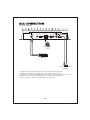
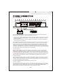
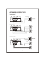
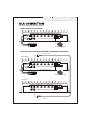
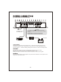
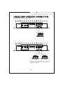
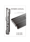
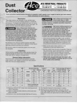
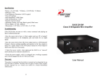
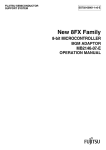
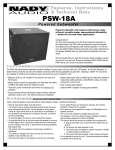
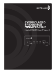
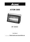
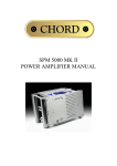
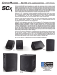
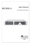
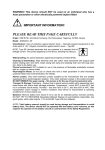
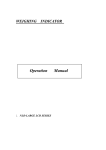
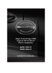
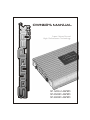
OWNER'S MANUAL
Super Natural Sound
High Performance Technology
SP-1200.2 dbPRO
SP-2500D dbPRO
SP-3000D dbPRO
[SP-1200.2 dbPRO]
2/1 Channel Bridgeable Class A/B Amplifier
MOSFET PWM Power Supply
4 Ohm Bridged / 2 Ohm Stereo Stability
24dB Octave Crossover Slope
Variable Low Pass Filter (LPF)
Variable High Pass Filter (HPF)
HPF/FULL/LPF Selectable Switch
Variable Bass Boost
On/Off Subsonic Switch
RCA Line Input and Output
Multi-Way Protection circuitry (Thermal/Over Current/Speaker Shor t /Speaker DC protection)
Tested Voltage & THD:14.4V & Less than 0.05% THD
Operating Voltage : DC10V~15.5V Power Input
Wired Remote Controller
[SP-2500D dbPRO]
Digital Class-D Linkable Mono Block Amplifier
Double Sided Through Hole Epoxy PCB
Stable into 1 Ohm Load Workable
Daisy-Chain Through Output RCA
Two Amp Linkable Function : Output Master and Input Slave
Efficiency : 86% @ 4 ohm, at 100Hz
24dB/Oct Variable Crossover
Multi-Way Protection Circuitry (Thermal/Over Current/Speaker Short /Speaker DC Protection)
RCA Line Input
Variable Subsonic Filter
Variable Bass Boost
Variable Low Pass Filter
Variable Phase Shift
Zero(0) Gauge Power Supply Connectors
Tested Voltage & THD : 14.4V & Less than 1% THD
Operating Voltage : DC 10V~16V Power Input
Wired Remote Controller
[SP-3000D dbPRO]
Digital Class-D Linkable Mono Block Amplifier
Double Sided Through Hole Epoxy PCB
Stable into 1 Ohm Load Workable
Daisy-Chain Through Output RCA
Two Amp Linkable Function : Output Master and Input Slave
Efficiency : 86% @ 4 ohm, at 100Hz
24dB/Oct Variable Crossover
Multi-Way Protection Circuitry (Thermal/Over Current/Speaker Short /Speaker DC Protection)
RCA Line Input
Variable Subsonic Filter
Variable Bass Boost
Variable Low Pass Filter
Variable Phase Shift
Zero(0) Gauge Power Supply Connectors
Tested Voltage & THD : 14.4V & Less than 1% THD
Operating Voltage : DC 10V~16V Power Input
Wired Remote Controller
-2-
[SP-1200.2 dbPRO]
INPUT
OUTPUT
CH1/L
CH1/L
SUB
SENSITIVITY SONIC
OFF
REMOTE
LPF
HPF
ON
FULL
LPF HPF
BASS
BOOST
Protection
Min
Max
30Hz 250Hz
50Hz
500Hz
CH2/R
0dB
18dB
Power
CH2/R
Wired Remote
Control
HEAD UNIT
to INPUT of ADDITIONAL
AMPLIFIERS
This amplifier has a signal input terminal of RCA connector type for low level inputs.
Adjustment of input levels is accomplished by the gain control of both channels.
Adjusting this control allows the amplifier gain to be controlled to match and balance both channels.
The RCA input connector should be used when connecting the radio/cassette line out
and this connection is usually made using RCA-RCA connector wires.
-3-
[SP-1200.2 dbPRO]
GND
REM
B+
FUSE
SPEAKER OUTPUT
POWER
CH1
CH2
BRIDGE
to REMOTE Turn-on
from HEAD UNIT
GROUND
BATTERY
HEAD UNIT
It is important that you read this manual very carefully and follow it for your installation carefully.
Before you start your installation, please consider following concerns.
1. Disconnect the negative (-) battery cable before mounting the amplifier or making any connections.
Check the battery and alternator ground (-) connections. Make sure they are properly connected
and free of corrosion.
2. Before selecting a mounting location for amplifier, please take some concerns into consideration
with cooling efficiency and safety.
This amplifier uses heavy-duty and good heat radiation heatsink design for avoiding excess heatsink
from amplifier circuitry. But for better heat radiation performance, it is good to find the mounting
location where you can install amplifier vertically with the heatsink fins and better air flow around
amplifier. For the safety, you have to find fry and well ventilated location and make sure any wires
cables and car equipment are not interfaced with amplifier installation. Be sure the mounting location
and drilling of pilot ables for mounting will not present a hazard to any wires, control cables, fuel lines,
fuel tanks, hydraulic ines or other vehicle systems or components.
3. Power connection
Before installing amplifier, disconnect the negative(-) wire from battery to protect any accidental
damage to your amplifier and system. Connection one end of fuse holder to the power cable and
the other end of fuse holder to positive battery within 20cm of the same cable. Connect the power
cable to the amplifier power terminal labeled as +12V. This fuse location will protect the system and
the vehicle against the possibility of a short circuit in the power cable. Be sure to use a fuse and fuse
holder adequate for the application. No fuse is required before the amplifier power connection.
4 Ground connection
Locate a secure grounding connection as close to the amplifier as possible. Make sure the location is
clean and provides a direct electrical connection to the frame of the vehicle. Connect one end of a
short piece of the same size cables as the power cable to the grounding point. Run the other end of
the cable to the amplifier mounting location.
Connectiot the ground cable to the screw terminal labeled as GND.
5. Remote connection
Run a remote turn on cable from the switched +12V source you will be using to turn on the system
components. This may be a toggle switch, a relay, or your source unit's remote trigger wire, or power
antenna trigger wire. Connect the remote turn on cable to the power terminal labeled as REM.
Run this lead to the amplifier mounting location. Using 16AWG wire or larger.
-4-
[SP-1200.2 dbPRO]
1 Channel Bridged
Speaker Impedance
4~8 ohms
SPEAKER OUTPUT
CH1-MONO
SUBWOOFER
CH1
CH2
BRIDGE
2 Channel Stereo
CH2
SPEAKER OUTPUT
CH1
Speaker Impedance
2~8 ohms
CH2
BRIDGE
CH1
3 Channel Tri Mode
CH3-MONO
SUBWOOFER
SPEAKER OUTPUT
CH1
Speaker Impedance
4~8 ohms
CH2
CH2
BRIDGE
CH1
-5-
[SP-2500D dbPRO & SP-3000D dbPRO]
Single Amp Input Connection
IN PUT
BR OUT
SENSITIVITY SUBSONIC
LPF
BASS BOOST PHASE
POWER
Min
Max
10Hz
60Hz
35Hz
300Hz
0dB
18dB
0
180
PROTECTION
REMOTE
CLASS-D LINKABLE MONO BLOCK AMPLIFIER
IN PUT
BR IN
HEAD UNIT
Wired Remote Control
Dual Amp Input Connection (MASTER & SLAVE RCA Connection)
to SLAVE UNIT "BR IN"
"MASTER UNIT"
IN PUT
BR OUT
SENSITIVITY SUBSONIC
LPF
BASS BOOST PHASE
POWER
Min
Max
10Hz
60Hz
35Hz
300Hz
0dB
18dB
0
180
PROTECTION
REMOTE
CLASS-D LINKABLE MONO BLOCK AMPLIFIER
IN PUT
BR IN
* BR OUT (BRIDGEABLE OUTPUT)
* BR IN (BRIDGEABLE INPUT)
HEAD UNIT
Wired Remote Control
"SLAVE UNIT"
IN PUT
BR OUT
SENSITIVITY SUBSONIC
LPF
BASS BOOST PHASE
POWER
Min
Max
10Hz
60Hz
35Hz
300Hz
0dB
18dB
0
180
PROTECTION
REMOTE
CLASS-D LINKABLE MONO BLOCK AMPLIFIER
IN PUT
BR IN
-6-
[SP-2500D dbPRO & SP-3000D dbPRO]
GND
REM
POWER
SPEAKER
B+
Caution
This amplifier is not supplied
with internal fuse in itself.
Make sure you install in-line
fuse holder from
the terminal of battery.
GROUND
Caution
to REMOTE Turn-on
from HEAD UNIT
This amplifier is not supplied with internal fuse in itself.
Make sure you install in-line fuse holder from the +terminal
of battery.
SP-2500D dbPRO : Recommend 200 Ampere fuse.
SP-3000D dbPRO : Recommend 300 Ampere fuse.
GROUND
HEAD UNIT
To +12V DC
BATTERY
+12V Power
Connect the +12V terminal of the amplifier to the + terminal of the battery using the same
diameteras the ground cable, making sure you install in-line fuse holder, approximately 300 or
400 mm. From the + terminal of battery, making sure that there is no fuse in the battery holder.
GROUND
Disconnect the battery and connect the GND (ground) terminal to the cars chassis.
Keep this cable as short as possible (not longer than 500 mm. or less).
Making sure that the connection with the chassis is rust free and clear of paint or grime.
REMOTE
Connect the REM terminal of the amplifier to the power antenna terminal in the car ignition switch
using 12 or 16 ga. electrical wire.
-7-
[SP-2500D dbPRO & SP-3000D dbPRO]
GND
REM
SPEAKER
B+
Caution
POWER
This amplifier is not supplied
with internal fuse in itself.
Make sure you install in-line
fuse holder from
the terminal of battery.
-
+
1~4 ohms
GND
POWER
REM
SPEAKER
B+
Caution
This amplifier is not supplied
with internal fuse in itself.
Make sure you install in-line
fuse holder from
the terminal of battery.
+
-
2~8 ohms
-
+
2~8 ohms
The positive and negative terminal of the subwoofer's
voice coil are connected to the positive and negative
terminal of the Amplifier.
-8-
[SP-2500D dbPRO & SP-3000D dbPRO]
"MASTER UNIT"
GND
REM
SPEAKER
B+
Caution
POWER
This amplifier is not supplied
with internal fuse in itself.
Make sure you install in-line
fuse holder from
the terminal of battery.
to REMOTE Turn-on
from HEAD UNIT
Recommended Ampere
SP-2500D dbPRO:200A (External Type Fuse)
SP-3000D dbPRO:300A (External Type Fuse)
+
GROUND
2~8
ohms
-
To +12V DC
HEAD UNIT
BATTERY
Use 8 Gauge(AWG) wire cable
"SLAVE UNIT"
GND
REM
SPEAKER
B+
Caution
POWER
This amplifier is not supplied
with internal fuse in itself.
Make sure you install in-line
fuse holder from
the terminal of battery.
GROUND
to REMOTE Turn-on
from HEAD UNIT
SP-2500D dbPRO:200A (External Type Fuse)
SP-3000D dbPRO:300A (External Type Fuse)
To +12V DC
HEAD UNIT
BATTERY
Using a dual amplifier configuration, the MASTER amplifier has total control over the SL AVE amplifier.
When using dual amplifier to operate subwoofer, the positive terminal of the subwoofer's voice coil
must be connected to the positive terminal of the MASTER Amplifier and the negative terminal of the
subwoofer's voice coil must be connected to positive terminal of the SLAVE Amplifier.
When hooking two amplifiers to it, please check the power handling capabilities of your subwoofers
if they are not exceeded.
Caution
In linkable/bridgeable mode connection, total impedance must be more than 2
Any impedance (load) smaller than 2 could damage the amplifier.
-7-
-9-
load.
This power amplifier has protection features to prevent any damages from misuse or faulty conditions.
If the unit senses excessive heat, short circuited speakers or overload, the protection indicators will light,
and the system will be turned off. In order to check the occurred problem, you should turn all levels
down and all power off and carefully check the installation for wiring mistakes or short. If the amplifier
shuts down due to excessive heat, the protection indicators will not light : simply allow time for the unit
to cool. Before removing your amplifier, refer to the list below and follow the suggested procedures.
Always test the speakers and their wires first.
AMPLIFIER IS NOT POWERED UP
Check that there is battery power on the +12V terminal.
Check that remote terminal has at least 13.8V DC remote connection.
Check a good ground connection. Check all fuses.
Check the protection LED is not lit.
PROTECTION LED ILLUMINATES WHEN AMPLIFIER IS POWERED UP
Check shorts on speaker wires.
Remove speaker wires and reset the amplifier. If the protection LED still comes on,
then the amplifier is faulty.
FUSE BLOWING
Check that the minimum speaker impedance is correct.
Check short on power cable and vehicle chassis.
OVERHEATING
Check that the minimum speaker impedance is correct.
Check speaker shorts.
Check that there is a good airflow around the amplifier.
SOUND TOO LOW-DISTORTED SOUND
Check that the input level control is set to match the output level of the unit.
Check the head unit volume.
Check speaker shorts.
Check that crossover frequencies have been properly set.
HIGH HISS-ENGINE NOISE IN SPEAKERS
Check a good ground and for speaker shorts.
Disconnect all RCA inputs from the amplifier. If hiss/noise disappears, check it with a good RCA
interconnect. Then check the component driving the amplifier.
-10-
[SP-1200.2 dbPRO]
Rated power output
-RMS power, 4 ohm stereo
-RMS power, 2 ohm stereo
-RMS power, 4 ohm bridged
Signal to Noise Ratio
Low Pass Crossover
High Pass Crossover
Subsonic Seletable @ on
Bass Boost @ 45Hz
Frequency Response
THD@RMS Watts
Channel Separation
Fuse Rating
Input Sensitivity
Dimensions
350W x 2CH
560W x 2CH
1120W x 1CH
>98dB
30Hz ~ 250Hz
50Hz ~ 500Hz
30Hz
0~18dB
10Hz ~ 40KHz (+/-1dB)
0.05%
75dB
30A x 4
200mV~5V (+/- 5%)
256(W) x 61(H) x 534(L)mm
[SP-2500D dbPRO]
Rated power output
-RMS power, 2 ohm linkable/dual mono
-RMS power, 1 ohm mono
-RMS power, 2 ohm mono
-RMS power, 4 ohm mono
Signal to Noise Ratio
Low Pass Crossover
Subsonic filter
Bass Boost @ 45Hz
Phase Shift Control
Frequency Response
THD@RMS Watts
Efficiency @ 4 ohm
Fuse Rating
Input Sensitivity
Dimensions
4500W x 1CH
2500W x 1CH
1400W x 1CH
700W x 1CH
>98dB
35Hz~300Hz
10Hz~60Hz
0~18dB
0~180 degree
10Hz~350Hz (+/- 1dB)
<1.00%
86%
200A(External Type)
200mV~6V (+/- 5%)
256(W) x 61(H) x 534(L)mm
[SP-3000D dbPRO]
Rated power output
-RMS power, 2 ohm linkable/dual mono
-RMS power, 1 ohm mono
-RMS power, 2 ohm mono
-RMS power, 4 ohm mono
Signal to Noise Ratio
Low Pass Crossover
Subsonic filter
Bass Boost @ 45Hz
Phase Shift Control
Frequency Response
THD@RMS Watts
Efficiency @ 4 ohm
Fuse Rating
Input Sensitivity
Dimensions
5400W x 1CH
3000W x 1CH
1600W x 1CH
800W x 1CH
>98dB
35Hz~300Hz
10Hz~60Hz
0~18dB
0~180 degree
10Hz~350Hz (+/- 1dB)
<1.00%
86%
300A(External Type)
200mV~6V (+/- 5%)
256(W) x 61(H) x 594(L)mm
The above specifications shall be modified by manufacturer for improvement without prior notice.
-11-