1
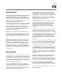
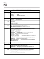
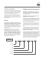
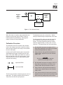
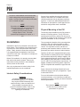
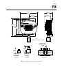
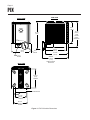
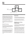
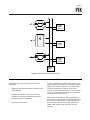
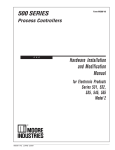
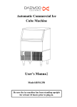
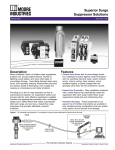
PIX
Pressure-to-Current Transmitter
USER’S MANUAL
October 1992
© 1992 by Moore Industries-International, Inc.
No. 123-701-00 B
Table of Contents
Introduction
1
Description
1
Calibration
4
Installation
6
Operation
10
Maintenance & Troubleshooting
10
Appendix A — Intrinsic Safety Requirements
A1
HR.
DELIVERY
8
4
UnitedStates/Canada
TOLLFREE
1-800-999-2900
United Kingdom
FREEPHONE
0800 525107
Australia
TOLLFREE
008 251928
Ask for the STAR Center
16650 Schoenborn Street
Sepulveda, California 91343, U.S.A.
Tel: (818) 894-7111 • Tlx: 65-1322
FAX: (818) 891-2816
CONNECT (MacNet): MIISEPULVEDA
1 Lloyds Court, Manor Royal, Crawley
W. Sussex RH10-2QU, United Kingdom
Tel: 0293 514488 • Tlx: 87667
FAX: 0293 536852
Moore Industries’ STAR* Center has a
wide variety of quality instrumentation
in stock and ready to ship.
• Signal Transmitters
• Temperature Transmitters
• P/I and I/P Converters
• Isolators and Converters
• Indicators and Displays
• Alarm Trips
• Integrators and Totalizers
• Power Transducers
• Instrument Power Supplies
• Racks, Rails and Enclosures
Most instruments can be customized
to meet your needs. Even then, you’ll
never have to wait more than a few days.
Moore Industries
3/18 Resolution Drive, Caringbah
New South Wales 2229, Australia
Tel: (02) 525-9177 • Tlx: 790-75914
FAX: (02) 525-7296
CENTER
*Support, Technical Assistance, and Repair (our Quick-Ship Facility)
PIX
Page 1
Introduction
The version of Moore Industries’ Pressure-to-Current
Transmitter packaged in the Hockey-puck (HP) or
Explosionproof (EXI) housing style is called the PIX.
The PIX is used to effect proportional changes in the
current of a 4-20 mA process instrumentation loop,
based on changes in pneumatic input.
This manual contains all of the information needed to
calibrate, operate, and maintain the PIX. It also
includes a brief description of the unit and its capabilities and options, a listing of unit specifications,
and an overview of Moore Industries’ unit data
tracking system and labeling.
An appendix at the end of the manual provides the
information required for installing the PIX in hazardous environments. Such installations require one of
the available Intrinsic Safety (IS) options, described
later.
Where they appear in text or figures, “NOTES” are
used to draw attention to practices that could otherwise result in inconveniences to the user. “CAUTIONS” call out information that, if ignored, could
result in damage to the unit, and “WARNINGS” point
out aspects of installation or operation that require
special attention. Unheeded warnings could result in
personal injury.
Description
The PIX is a two-wire (loop-powered) transmitter that
accepts variable, instrument-quality, pneumatic input
and converts it proportionally to current output in the
4-20 mA range. As input pressure increases, output
increases proportionally toward 20 mA. Inversely, as
pressure decreases, output drops.
The unit is configured at the factory, according to
customer specification, to accept pneumatic input in
any one of several ranges. It can function in a
single-instrument loop or together with several PIX’s
inter-connected in a pneumatic system.
The available housing styles for the PIX, which
include several versions of both the HP and EXI
type, afford the user with a wide variety of mounting
options. Contact your Moore Industries’ Sales
Representative for more information on available
mounting hardware and options.
The HP-style PIX. This unit is intended to function
as a modular replacement in applications where
conduit and enclosures may already be in place,
when a special enclosure is not required, or in
applications where the EXI PIX is not otherwise
appropriate.
Typically, this style of PIX is mounted in a separate,
domed, explosionproof enclosure. It is secured
inside this enclosure with two spring clips; no drilling
or tapping is required. Other versions of the HP-style
PIX include hardware for surface mount or relay
track installations. With an available adapter, the unit
can also be snapped on to G-type DIN rail (DIN
EN50035).
Pneumatic input connections for the HP-style PIX are
female, 1/4-18 NPT. The electrical conduit connection hubs for the unit when used with Moore Industries’ explosionproof enclosure are 1/2-14 NPT .
The EXI-style PIX. This housing is designed to meet
the requirements of several independent certifying
agencies in applications calling for intrinsically safe
equipment. It provides the unit with excellent protection from even the most arduous of industrial environments.
With the EXI-style PIX, the electronics and the
housing are integrated into an extruded aluminum,
explosionproof unit. The EXI is available with or
without pipe mounting hardware, and the electrical
conduit connection port can be ordered in either a
1/2-14 NPT configuration, or with an M20 x 1.5
(metric) port opening. As with the HP-style unit,
pneumatic input connections are female, 1/4-18 NPT.
Table 1 contains the PIX performance and operational specifications.
PIX
Page 2
Table 1. PIX Operational and Performance Specifications
Characteristic
Specifications
Input
(see NOTE 1)
Factory-configured. Instrument-quality air input only.
0-15 psig
3-27 psig
0-30 psig
6-30 psig
0-100 psig
20-100 kPa (0.2-1 bar, 0.2-1 kgcm
3-15 psig
20-186 kPa
Input Pressure Maximum:
Output
4-20 mA
Output Limit:
Power
2
)
150% of rated full-scale input without damage.
130% of rated output span.
Loop-powered.
12-42 Vdc , standard
12-24 Vdc
(see NOTE 2)
12-28 Vdc
(see NOTE 2)
Controls
Zero: Multiturn pot electronically provides offsets of ±10% of span.
Span: Multiturn pot electronically provides full adjustability to 100% of span.
Zero and Span pots are non-interactive.
Performance
Accuracy:
Error less than ±0.2% of unit span, including the effects of independent linearity, as
defined per SAMA standard PMC 20.1-1973.
Repeatability:
±0.1% of input span.
Resolution:
±0.05% of input span.
Response Time:
Load Capability:
Load Effect:
Output Ripple:
10 milliseconds to reach 98% of output for each step change on input.
600 at 24 Vdc nominal.
±0.01% of rated span from zero to maximum rated load.
Negligible.
Power Supply Line Voltage Effect:
voltage at power input terminals.
RFI/EMI Effect:
frequencies.
Vibration Effect:
Less than 0.1% of rated span in field strengths of 10 V/m at typical walkie-talkie
Negligible. Unit has no internal moving parts.
Effect of Ambient Temperature:
temperature operating range.
Environmental
Ratings
Ambient Temperature Operating Range:
Weight
Less than ±0.01% of rated span per volt of change in line
Less than ±2% of full-scale input over the specified ambient
–1 to 54 °C (30 to 130 °F).
EXI-style Housing:
Approximately 1.25 kg (2 lb, 13 oz) without options. 1.4 kg (3 lb, 2 oz)
including mounting flange, option block, gage, and test jack options.
HP-style Housing:
Approximately 227 g (8 oz) with standard flange mount hardware and
pneumatic input connection fitting. 1.4 kg (3 lb 2 oz) in explosionproof enclosure.
NOTES:
1. Not all listed specifications are standard. Consult your Moore Industries’ Sales Representative
for information on pricing and availability.
2.
Required for some types of IS applications (Consult your Moore Industries’ Sales
Representative for details).
3. Refer to the Installation Section for PIX outline dimensions.
PIX
Page 3
Controls and Indicators
RO Option – Reverse Output. As input air pressure
increases, current output decreases toward 4 mA.
There are two, multiturn potentiometers (pots) used
to adjust PIX zero and span. Each pot is equipped
with a slip clutch mechanism to prevent damage in
the event it is turned beyond its wiper stop.
The pots are located on the front panel of HP units.
They can be found on the top panel of EXI PIX’s,
which is accessed by unscrewing the top end-cap of
the unit housing.
PTJ Option – Pneumatic Test Jack. Fitting for
connection of test equipment to monitor input pressure (test equipment not included). Available with
the EXI housing only.
GA1 Option – Input Gage. Scaled in psi and bars.
Available with the EXI housing only.
Unit Data Tracking – Model/Serial Number. Moore
Industries keeps a record of product information on
every unit sold or serviced. This record is keyed to
the unit model and serial numbers.
Options
The following list provides an overview of some of
the PIX options. Complete information on mounting
hardware and functional options, or currently available certifications and approvals is available from
your Moore Industries Sales Representative. Users
may also contact the factory directly at 1-800-9992900 in the U.S.A.
IS(x) Option(s) – Instrinsic Safety. Units can be
configured to comply with the requirements of
several, independent IS certifications. Contact the
factory, or your local Moore Industries’ Sales Representative for information on the specific approvals
available. The appendix of this manual provides
information on the installation of some IS-equipped
PIX’s in applications calling for IS.
On the HP-style PIX, look for the model and serial
numbers on a label affixed to the back panel. The
tag on EXI-style units is on the bottom cover (endcap).
The following example shows a typical PIX model
number, breaking out its data fields for illustration
purposes. Refer to the example in deciphering the
model number on your RBX.
If service assistance is ever required, make a note of
the unit model number before contacting the factory.
For fastest assistance, also note the unit serial
number, job number, and the purchase order number
under which it was shipped. This information assists
the factory representative in providing you with the
answers you need as efficiently as possible.
EXAMPLE
PIX / 3-15PSIG / 4-20MA / 12-42DC / -RO [ EXIP ]
Unit Type
Input
Output
Power
Option(s)
Housing
PIX
Page 4
Calibration
Prior to shipment, every PIX is fully tested to ensure
compliance with Moore Industries’ strict quality
control guidelines. Before installation, however, your
PIX(s) should be bench checked in order to set and
verify the desired operating levels.
This procedure should be conducted in an environment considered appropriate for general testing of
electronic and pneumatic equipment. It is recommended that the procedures in this section not be
carried out in the field. Use a technician’s bench or
in a similar lab-type setup, so that any unit damage
that may have occurred during shipment can be
discovered safely, i.e., separated from the intended
process or application.
Calibration Setup
Table 2 lists the equipment required to calibrate the
PIX. This equipment is not supplied by Moore
Industries, but should be available in most labs or
maintenance areas.
The terminals for connection of the calibration
equipment are located on the unit front panel. Both
types of housing style use the same type of 6terminal block. Each terminal is numbered, but only
terminals 1 and 3 are active in the PIX.
Terminals are labeled “+I” (terminal 1) for connection
of the positive lead, and “–I” (terminal 3) for connection of negative.
Figure 1 illustrates the generic hookup required to
perform the bench check and pot adjustments of the
PIX. Connect the equipment listed in table 2 as
shown in figure 1.
NOTE
If the unit being checked is equipped with
the Test Jack or Gage Option (EXI
housing only), the input pressure may be
monitored during calibration. Note that
connecting the appropriate measurement
instrument to the PIX test jack fitting has
no effect on pneumatic load.
Table 2. PIX Calibration Equipment
Equipment
Air Supply
Air Pressure Gage
Power Source
DC Voltmeter
Precision Resistor
Screwdriver
Characteristics
Calibrated, adjustable, regulated, instrument-quality. Must be capable of
discrete output levels within the appropriate, rated range of the unit under test.
Refer to table 1 for appropriate maximum/minimum specifications.
Calibrated. Accuracy of ±0.05%, scaled as appropriate for the specified input of
the unit being calibrated.
Calibrated. 12-42 Vdc, capable of 4-20 mA output.
Calibrated. Accuracy of ±0.005%, minimum.
250 , ±0.01%
Slotted-tip. Head width of 2.54 mm (0.1 in), maximum.
PIX
Page 5
+
+I
PNEUMATIC
INPUT
(REFER TO
TABLE 1)
12-42 VDC
POWER
SOURCE
PIX
250
–I
–
+
–
DC VOLTMETER
Figure 1. PIX Calibration Setup
When the setup is complete, apply appropriate input
pressure and dc power (refer to table 1 and unit
model number for specifications). Allow approximately 5 minutes for setup stabilization.
Calibration Procedure
The calibration of the PIX consists of the measurement of the voltage drop across a precision resistor
when the input pressure in the setup is varied within
the unit’s rated span.
In both the HP and EXI housing style, the zero and
span adjustment pots are located on the PIX front
panel. The words “ZERO” and “SPAN” are used as
labels for the pots on the HP unit front panel. In the
case of the EXI PIX, they are represented symbolically with the following:
represents ZERO
The adjustment pots are not interactive. Neither
setting is effected during the adjustment of the other.
To calibrate the PIX, make sure that the setup has
been completed as described in the preceding
section. Turn both adjustment pots fully counterclockwise (approximately 15 turns), then 7.5 turns
clockwise. This approximates the mid-scale setting.
1. Set adjustable instrument air supply to 0% of
input range specified for unit (refer to unit model
number and specifications in table 1).
2. Using voltmeter with specified load resistor to
monitor output, adjust Zero pot until voltmeter
reads 1 volt.
CAUTION
Use of a screwdriver larger than that
specified may damage the PIX.
3. Set adjustable instrument air supply to 100% of
input range as specified for unit (refer to unit
model number and specifications in table 1).
represents SPAN
4. Using voltmeter with specified load resistor to
monitor output, adjust Span pot until voltmeter
reads 5 volts.
The Zero pot provides for offsets as great as ±10% of
rated span. The Span pot adjusts unit full-scale to
100-percent at maximum input pressure.
5. Verify proper settings by varying input pressure
between maximum and minimum specified levels
while monitoring voltage drop across resistor.
PIX
Page 6
As input is varied between zero and full-scale,
output voltage drop varies proportionally between 1 volt (for zero) and 5 volts (for full-scale),
±0.2% of rated unit span.
NOTE
If checking unit equipped with RO Option,
observed voltage will vary inversely with
respect to pressure. That is, 0%
pressure input will produce full-scale
voltage output, 5 volts. Full-scale
pressure input produces 0% output, or 1
volt.
Installation
Installation of the PIX is presented in this manual in
three phases. The first phase is the physical mounting of the unit. Next is the pneumatic connections
phase. Finally, electrical connections can be made.
It is suggested that the installation of the PIX be
carried out in this order. Information on multiple-unit
hookups is included.
Before PIX installation, it is strongly recommended
that each unit be bench checked. Refer to the
instructions for this procedure in the Calibration
Section, earlier in this manual.
Also, any requirements for intrinsic safety in the
intended application must be considered.
Intrinsic Safety Considerations
WARNING
If installing the PIX in a hazardous
environment application, i.e., one that
may require certified intrinsically safe
systems hookup, make sure that the unit
being installed is equipped with the
proper IS certification option. Refer to the
appendix of this manual for information
regarding IS installations.
Several of the available housing and enclosure
options in which the PIX is available have been
certified Intrinsically Safe by third party certifying
agencies. Consult your Sales Representative for
information on the specifics of each approval and
with which configurations each is available.
Physical Mounting of the PIX
The housing styles available for the PIX present a
number of mounting options. The HP PIX in the
explosionproof enclosure, and the EXI unit can be
mounted on virtually any flat surface or, with optional
pipe-mount hardware, on any 2-inch pipe.
The symmetrical orientation of the mounting holes
used in the EXI unit makes it possible to effect
mounting in virtually any orientation, horizontal or
vertical. It is important, however, that the unit
positioning and orientation allow for access to the
pneumatic port and the electrical conduit opening.
Typically, the HP unit is equipped with spring clips.
This provides for installing the unit in the explosionproof enclosure without any drilling or tapping. HP
units equipped with flanges can be used in applications calling for either relay track or surface mount
use (FL and FLD housing options, respectively). An
adapter, available as a housing option, makes the
HP PIX compatible with standard, G-type DIN rails
(DN).
Figure 2 shows the mounting dimensions for the
PIXwith the flange mount (FL) configuration. Figure
3 shows the EXI PIX.
For more information on these options and pipe
mounting hardware, or for information on options or
enclosures not shown, contact your Moore Industries
Sales Representative.
NOTE
The orientation of the unit (horizontal,
vertical, etc.) has no effect on PIX
performance or operation.
PIX
Page 7
75.4 mm
(2.97 in)
44.5 mm
(1.75 in)
42.7 mm
(1.68 in)
37.8 mm
(1.5 in)
GND
82.5 mm
(3.25 in)
72.6 mm
(2.86 in)
+I –I
1
ZERO
3
2
5
4
SPAN
6
61 mm
(2.4 in)
1/4 in
NPT FITTING
SLIDE CLIP FOR
SECURING PNEUMATIC
FITTING
41.3 mm
(1.63 in)
20.6 mm
(0.82 in)
FITTING USED
WITH HP UNIT,
NO MOUNTING
HARDWARE
FITTING USED
WITH FLANGE
MOUNT
HARDWARE
Figure 2. HP PIX with Flange Mount Hardware
BOTTOM VIEW
PIX
Page 8
SIDE VIEW
FRONT VIEW
98 mm
(3.85 in)
116 mm
(4.55 in)
WITH
OPTION
BLOCK
INSTALLED
127 mm
(5.0 in)
PIX
PRESSURE TO
CURRENT TRANSMITTER
89 mm
(3.5 in)
-GA1
OPTION
-PTJ
OPTION
102 mm
(4.00 in)
114.3 mm
(4.50 in)
APPROX.
145 mm
(5.7 in)
WHEN OPTION IS
INSTALLED
REAR VIEW
88.9 mm
(3.5 in)
SQUARE
PIF
PRESSURE TO
CURRENT TRANSMITTER
OPTION BLOCK
57.2 mm
(2.25 in)
SQUARE
69.9 mm
(2.75 in)
SQUARE
Figure 3. EXI PIX Outline Dimensions
PIX
Page 9
Pneumatic Connections
The first phase of PIX installation consists of connecting the pneumatic input line. The following
suggestions are made regarding the connection of
the pneumatic input to the PIX:
•
Provide independent support for any components or equipment installed in the lines. Cushioning brackets are best.
•
Avoid “straight-line” connections, if possible.
•
Seal all fittings with Teflon tape or equivalent.
“Pipe dope” is not recommended. If your application environment prohibits the use of Teflon,
contact Moore Industries for assistance.
•
Always “blow down” or purge all tubing before
connecting to the PIX.
NOTE
On the EXI PIX’s equipped with the PTJ
Option, a removable plug (1/8 in NPT) is
placed in the unused port, unless the unit
is also equipped with the Gage Option,
GA1.
Before connecting a pneumatic input line to the PIX,
ensure that the line is free of debris. Use the methods recommended by the maintenance section of
your facility. Absent that, apply high input pressure
(up to 60 psig) to the line until the flow is clear.
CAUTION
Air nozzles, nipple, and valves should be
lubricated before installation. Teflon®
spray lubricant is recommended. If a
substitute is used, exercise extreme care
to ensure that it is kept out of the unit’s air
passage and input line.
Electrical Connections
The PIX has two electrical connection terminals,
labeled “+I” and “–I”, on its front panel. These are for
the connection of wiring for the unit’s 4-20 mA output.
Figure 4 shows the electrical hookup diagram for the
PIX.
As the PIX is a loop-powered device, no additional
electrical connections are required. Check the
Power field of the unit model number to verify
appropriate loop voltage. Refer to the explanation of
the model number in the Description Section of this
manual, and to the specifications listed in table 1 for
more information.
CAUTION
Certain Intrinsic Safety Certification
options for the PIX carry restrictions for
the unit power (loop voltage). Refer to
the appendix of this manual, or consult
with your Moore Industries’ Sales
Representative for details.
As shown in figure 4, connect the +I terminal of the
PIX to the positive lead from the power source in the
loop. Connect the –I PIX terminal in series with the
positive terminals of the other devices in the loop,
and the negative terminal of the loop power supply.
Terminal wires used should be between 14 and 22
AWG. Connections are made with compressionscrew sockets. Use a slotted-tip screwdriver with a
head width no greater than 3 mm (0.12 inch).
NOTE
The use of shielded, twisted-pair wiring,
grounded as near as possible to the PIX,
is recommended.
The enclosure in which explosionproof
HP units are shipped, as well as the
housing of EXI PIX’s, have a built-in
grounding screw. In the case of the
explosionproof HP PIX, it is located on
the interior wall of the enclosure, opposite
the port used for connection of the
pneumatic input. On EXI units, it is
located inside the electrical connections
compartment of the housing, next to the
conduit port.
PIX
Page 10
APPROPRIATE
DC POWER
SOURCE
+
–
–
+I
PNEUMATIC
INPUT
CURRENT
DRIVEN
DEVICE
PIX
4-20 mA
–I
+
Figure 4. PIX Installation Hookup
Grounding. To ground the HP PIX make sure a
shielded grounding lead is connected to the GND
screw on the unit front panel. This screw is located
to the right of the Zero adjustment pot, and is typically fitted with a wire or wire terminating lug.
Typically, in the case of HP units in explosionproof
enclosures, the unit grounding screw is attached to
the enclosure ground prior to shipment.
To ground the EXI PIX, run the shielded grounding
lead through the housing’s wiring conduit port, and
connect it to the screw on the interior wall of the
housing.
Multiple PIX Hook-ups
Some precautions must be taken when powering
more than one PIX in a single loop. Make sure that
one side of the power source is common to all PIX’s,
and that the other side of the power source is
common to all loads.
Figure 5 shows an example of this type of hookup.
When using a single source to power multiple units,
care must be taken to avoid ground loop problems
due to the loads being at different potentials. If
separate power supplies cannot be employed,
contact your Moore Industries Sales Representative
for assistance is selecting a compatible signal
isolator.
Operation
Once properly installed, supplied with pneumatic
input, and connected to load instrumentation in the
process loop, PIX transmitters operate unattended.
If a unit is determined to be the cause of a loop
discrepancy or malfunction, refer to the Troubleshooting Section of this manual for instructions.
Maintenance & Troubleshooting
PIX transmitters are built with highly reliable components and contain no moving parts. These two
aspects ensure that these units operate reliably for
extended periods of time.
Once installed and operating, the PIX requires no
field maintenance other than an occasional visual
inspection of the unit connection terminals and
pneumatic connection. This inspection is recommended at least once every six months, or more
frequently in those installations where the unit is
subjected to extremes in vibration or dust and dirt.
Field troubleshooting of the PIX is limited to visual
inspection of the housing, the pneumatic connections, and verification of specified signal response.
PIX
Page 11
+
+
–
–
CURRENT
DRIVEN
DEVICE
+
+
–
–
CURRENT
DRIVEN
DEVICE
+
+
–
–
+
CURRENT
DRIVEN
DEVICE
–
POWER
SUPPLY
Figure 5. Multiple PIX Installation Hookup
If problems arise in the function of the unit in its
application:
•
Make sure that input and output connections are
clean and tight.
•
Remove the unit from service and reclibrate,
making sure that bench instruments used are
themselves properly calibrated.
•
Verify loop power levels.
If, after re-calibration, the PIX fails to perform up to
specifications, contact the factory Customer Service
Department. Phone numbers of your local STAR
Center are listed inside the front cover of this
manual. Instructions for the return of the unit to the
factory for further testing or rehab can be found on
the back cover of this manual.
When calling for assistance, always remember to
provide your Customer Service Representative with
the model and serial number of the offending unit,
and if possible, with the job number and the purchase order number under which the unit was
ordered.
RETURN PROCEDURES
To return equipment to Moore Industries for repair, follow these four steps:
1. Call Moore Industries and request a Returned Material Authorization (RMA) number.
Warranty Repair –
If you are unsure if your unit is still under warranty, we can use the unit’s serial number
to verify the warranty status for you over the phone. Be sure to include the RMA
number on all documentation.
Non-Warranty Repair –
If your unit is out of warranty, be prepared to give us a Purchase Order number when
you call. In most cases, we will be able to quote you the repair costs at that time.
The repair price you are quoted will be a “Not To Exceed” price, which means that the
actual repair costs may be less than the quote. Be sure to include the RMA number on
all documentation.
2. Provide us with the following documentation:
a) A note listing the symptoms that indicate the unit needs repair
b) Complete shipping information for return of the equipment after repair
c) The name and phone number of the person to contact if questions arise at the factory
3. Use sufficient packing material and carefully pack the equipment in a sturdy shipping
container.
4. Ship the equipment to the Moore Industries location nearest you.
The returned equipment will be inspected and tested at the factory. A Moore Industries
representative will contact the person designated on your documentation if more information is
needed. The repaired equipment, or its replacement, will be returned to you in accordance with
the shipping instructions furnished in your documentation.
WARRANTY DISCLAIMER
THE COMPANY MAKES NO EXPRESS, IMPLIED OR STATUTORY WARRANTIES (INCLUDING ANY WARRANTY OF MERCHANTABILITY OR OF FITNESS
FOR A PARTICULAR PURPOSE) WITH RESPECT TO ANY GOODS OR SERVICES SOLD BY THE COMPANY. THE COMPANY DISCLAIMS ALL WARRANTIES ARISING FROM ANY COURSE OF DEALING OR TRADE USAGE, AND
ANY BUYER OF GOODS OR SERVICES FROM THE COMPANY ACKNOWLEDGES THAT THERE ARE NO WARRANTIES IMPLIED BY CUSTOM OR
USAGE IN THE TRADE OF THE BUYER AND OF THE COMPANY, AND THAT
ANY PRIOR DEALINGS OF THE BUYER WITH THE COMPANY DO NOT IMPLY THAT THE COMPANY WARRANTS THE GOODS OR SERVICES IN ANY
WAY.
ANY BUYER OF GOODS OR SERVICES FROM THE COMPANY AGREES
WITH THE COMPANY THAT THE SOLE AND EXCLUSIVE REMEDIES FOR
BREACH OF ANY WARRANTY CONCERNING THE GOODS OR SERVICES
SHALL BE FOR THE COMPANY, AT ITS OPTION, TO REPAIR OR REPLACE
THE GOODS OR SERVICES OR REFUND THE PURCHASE PRICE. THE
COMPANY SHALL IN NO EVENT BE LIABLE FOR ANY CONSEQUENTIAL OR
INCIDENTAL DAMAGES EVEN IF THE COMPANY FAILS IN ANY ATTEMPT
TO REMEDY DEFECTS IN THE GOODS OR SERVICES , BUT IN SUCH CASE
THE BUYER SHALL BE ENTITLED TO NO MORE THAN A REFUND OF ALL
MONIES PAID TO THE COMPANY BY THE BUYER FOR PURCHASE OF THE
GOODS OR SERVICES.
United States • [email protected]
Tel: (818) 894-7111 • FAX: (818) 891-2816
Australia • [email protected]
Tel: (02) 8536-7200 • FAX: (02) 9525-7296
© 2007 Moore Industries-International, Inc.
ANY CAUSE OF ACTION FOR BREACH OF ANY WARRANTY BY THE
COMPANY SHALL BE BARRED UNLESS THE COMPANY RECEIVES
FROM THE BUYER A WRITTEN NOTICE OF THE ALLEGED DEFECT OR
BREACH WITHIN TEN DAYS FROM THE EARLIEST DATE ON WHICH THE
BUYER COULD REASONABLY HAVE DISCOVERED THE ALLEGED DEFECT OR BREACH, AND NO ACTION FOR THE BREACH OF ANY WARRANTY SHALL BE COMMENCED BY THE BUYER ANY LATER THAN
TWELVE MONTHS FROM THE EARLIEST DATE ON WHICH THE BUYER
COULD REASONABLY HAVE DISCOVERED THE ALLEGED DEFECT OR
BREACH.
RETURN POLICY
For a period of thirty-six (36) months from the date of shipment, and under
normal conditions of use and service, Moore Industries ("The Company") will
at its option replace, repair or refund the purchase price for any of its manufactured products found, upon return to the Company (transportation charges
prepaid and otherwise in accordance with the return procedures established
by The Company), to be defective in material or workmanship. This policy
extends to the original Buyer only and not to Buyer's customers or the users
of Buyer's products, unless Buyer is an engineering contractor in which case
the policy shall extend to Buyer's immediate customer only. This policy shall
not apply if the product has been subject to alteration, misuse, accident, neglect or improper application, installation, or operation. THE COMPANY
SHALL IN NO EVENT BE LIABLE FOR ANY INCIDENTAL OR CONSEQUENTIAL DAMAGES.
Belgium • [email protected]
Tel: 03/448.10.18 • FAX: 03/440.17.97
The Netherlands • [email protected]
Tel: (0)344-617971 • FAX: (0)344-615920
China • [email protected]
Tel: 86-21-62491499 • FAX: 86-21-62490635
United Kingdom • [email protected]
Tel: 01293 514488 • FAX: 01293 536852
Specifications and Information subject to change without notice.