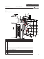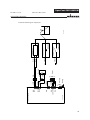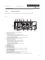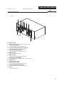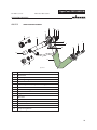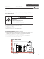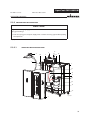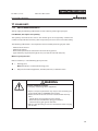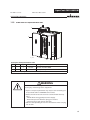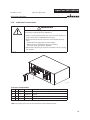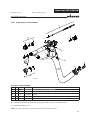
1
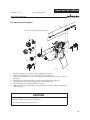
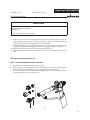
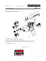
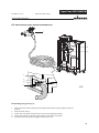
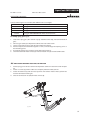
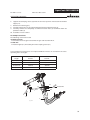
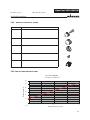
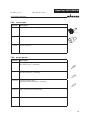
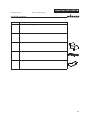
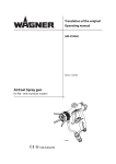
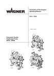
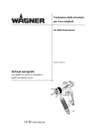
Translation of the original Operating manual AquaCoat Air -LDG20 -ZIP52 -3-130S -VM 2900W Edition 01/2008 AquaCoat air spray system for non-combustible liquids B_01881 EDITION 01/2008 PART NO. DOC353841 AquaCoat GM 2900EAW OPERATING MANUAL Contents 1 1.1 1.2 ABOUT THESE INSTRUCTIONS Languages Warnings, notes and symbols in these instructions 5 5 5 2 2.1 2.1.1 2.1.2 2.1.3 2.2 2.2.1 2.2.2 2.2.3 2.2.4 2.2.5 2.2.6 2.3 2.4 GENERAL SAFETY INSTRUCTIONS Safety instructions for the operator Electrical equipment Personnel qualifications A safe work environment Safety instructions for staff Safe handling of WAGNER spray units Earth the unit Paint hoses Cleaning Handling hazardous liquids, varnishes and paints Touching hot surfaces Correct use Safety-relevant information about discharges 6 6 6 6 6 6 7 7 7 8 8 8 8 8 3 3.1 3.2 3.3 3.4 PRODUCT LIABILITY AND WARRANTY Important notes on product liability Warranty CE-conformity German regulations and guidelines 9 9 9 10 11 4 4.1 4.1.1 4.2 4.2.1 4.3 4.3.1 4.3.2 4.3.4 4.3.5 4.3.6 4.4 4.4.1 4.4.1.1 4.4.1.2 4.4.1.2.1. 4.4.1.2.1.1 4.4.1.2.1.2 4.4.1.2.1.3 4.4.1.3 4.4.1.4 4.4.1.5 DESCRIPTION Fields of application, using in accordance with the instructions Processible materials. Extent of delivery Spraypack-Configuration Technical data Control unit VM 2900W Spray gun GM 2900EAW Material pressure tank LDG20 Double diaphragm pump ZIP52 Piston pump 3-130S PE+TG Functional description Design of the unit and Function Control unit VM 2900W Spray gun GM 2900EAW Air atomizing round and flat jet process Air atomizing round jet process Air atomizing flat jet process The electrostatic effect Material pressure tank LDG20 Double diaphragm pump ZIP52 Pneumatic pump 3-130S PE+TG 12 12 12 13 14 16 17 18 19 19 19 20 20 23 26 27 27 28 28 29 29 29 5 5.1 STARTING UP AND OPERATING Installation and connection 30 30 3 EDITION 01/2008 PART NO. DOC353841 AquaCoat GM 2900EAW OPERATING MANUAL Contents 5.1.1 5.1.2 5.1.3 5.1.4 5.1.5 5.1.5.1 5.1.5.2 5.2 5.2.1 5.3 5.3.1 5.3.2 5.3.2.1 5.3.2.2 5.3.2.3 5.4 5.4.1 5.4.2 5.4.3 5.4.4 5.4.5 5.4.6 Ventilation of the spray booth Air supply Fluid (paint) hoses Earthing Safety checks Earthing check Inspection of the safety elements Preparation of water paint Viscosity conversion table Start-up General rules for handling the spray gun Preparation for starting up Spraypack with pressure tank Spraypack with Double diaphragm pump Spraypack with pneumatic pump 3-130S Works Start-up for spraying with flat jet nozzle Adjust the spray angle by flat jet nozzles Exchange of round jet nozzle insert - round jet nozzle Changing from round jet nozzle to flat jet nozzle Control unit VM 2900W - formulas Control unit VM 2900W -Modification and storage of formulas 30 31 31 32 33 33 33 34 34 35 35 36 36 38 40 42 42 43 43 44 45 45 6 6.1 MAINTENANCE Finishing work and cleaning 46 47 7 TROUBLE SHOOTING AND SOLUTION 48 8 8.1 8.2 8.3 8.3.1 8.3.2 8.4 8.5 8.6 REPAIRS Replacing the valve seat assy. Replacing the valve rod Replacing the valve rod tip Starting from installed valve rod Starting from disassembled valve rod Replacing the end piece seal Replacing the spray gun including hose set Replacing the paint hose and/ or air hose 51 51 52 53 53 54 55 56 57 9 DISPOSAL OF THE PRODUCT 59 10 10.1 10.1.1 10.2 10.2.1 10.3 10.4 ACCESSORIES Nozzles EA Flat jet Output measured with paint Nozzles EA round jet (Supra) Output measured with paint Special tools Miscellaneous 60 60 60 61 61 62 62 11 11.1 11.2 11.3 11.4 SPARE PARTS How to order spare parts? Spare part list AquaCoat basic unit Spare parts list VM 2900W Spare parts list GM 2900EAW 64 64 65 66 67 4 EDITION 01/2008 AquaCoat GM 2900EAW PART NO. DOC353841 OPERATING MANUAL 1 ABOUT THESE INSTRUCTIONS 4HISOPERATINGMANUALCONTAINSINFORMATIONABOUTTHEOPERATIONREPAIRANDMAINTENANCE OFTHEUNIT !LWAYSFOLLOWTHESEINSTRUCTIONSWHENOPERATINGTHEUNIT 4HISEQUIPMENTCANBEDANGEROUSIFITISNOTOPERATEDINACCORDANCEWITHTHISMANUAL %LECTROSTATICSPRAYGUNSMAYBEOPERATEDONLYBYTRAINEDPERSONNEL #OMPLIANCEWITHTHESEINSTRUCTIONSCONSTITUTESANINTEGRALCOMPONENTOFTHEGUARANTEE AGREEMENT 1.1 LANGUAGES 4HISOPERATINGMANUALISAVAILABLEINTHEFOLLOWINGLANGUAGES ,ANGUAGE 0ART.O ,ANGUAGE 353840 'ERMAN %NGLISH 353842 &RENCH $UTCH 353844 )TALIAN 3PANISH -$ANISH 3WEDISH 1.2 0ART.O 353841 -353845 -- WARNINGS, NOTES AND SYMBOLS IN THESE INSTRUCTIONS Warning instructions in this manual point out particular dangers to users and equipment and state measures for avoiding the hazard. These warning instructions fall into the following categories: DANGER Danger - imminent danger. Non-observance will result in death, serious injury and serious material damage. This line warns of the hazard! Possible consequences of failing to observe the warning instructions. The signal word points out the hazard level. SIHI_0100_GB The measures for preventing the hazard and its consequences. WARNING Warning - possible danger. Non-observance can result in death, serious injury and serious material damage. This line warns of the hazard! Possible consequences of failing to observe the warning instructions. The signal word points out the hazard level. SIHI_0103_GB The measures for preventing the hazard and its consequences. CAUTION Caution - a possibly hazardous situation. Non-observance can result in minor injury. This line warns of the hazard! Possible consequences of failing to observe the warning instructions. The signal word points out the hazard level. The measures for preventing the hazard and its consequences. SIHI_0101_GB Caution - a possibly hazardous situation. Non-observance can cause material damage. SIHI_0102_GB CAUTION This line warns of the hazard! Possible consequences of failing to observe the warning instructions. The signal word points out the hazard level. The measures for preventing the hazard and its consequences. Note - provide information on particular characteristics and how to proceed. 5 EDITION 01/2008 PART NO. DOC353841 AquaCoat GM 2900EAW OPERATING MANUAL 2 GENERAL SAFETY INSTRUCTIONS 2.1 SAFETY INSTRUCTIONS FOR THE OPERATOR +EEPTHESEOPERATINGINSTRUCTIONSTOHANDNEARTHEUNITATALLTIMES !LWAYSFOLLOWLOCALREGULATIONSCONCERNINGOCCUPATIONALSAFETYANDACCIDENTPREVEN TION 2.1.1 ELECTRICAL EQUIPMENT %LECTRICALPLANTANDUNIT 4O BE PROVIDED IN ACCORDANCE WITH THE LOCAL SAFETY REQUIREMENTS WITH REGARD TO THE OPERATINGMODEANDAMBIENTINmUENCES -AYONLYBEMAINTAINEDBYSKILLEDELECTRICIANSORUNDERTHEIRSUPERVISION -USTBEOPERATEDINACCORDANCEWITHTHESAFETYREGULATIONSANDELECTROTECHNICALREGU LATIONS -USTBEREPAIREDIMMEDIATELYINTHEEVENTOFPROBLEMS -USTBEPUTOUTOFOPERATIONIFTHEYPOSEAHAZARD -USTBEDEENERGIZEDBEFOREWORKISCOMMENCEDONACTIVEPARTS)NFORMSTAFFABOUT PLANNEDWORKOBSERVEELECTRICALSAFETYREGULATIONS 2.1.2 PERSONNEL QUALIFICATIONS %NSURETHATTHEUNITISOPERATEDANDREPAIREDONLYBYTRAINEDPERSONS 2.1.3 A SAFE WORK ENVIRONMENT %NSURETHATTHEmOOROFTHEWORKINGAREAISANTISTATICINACCORDANCEWITH%.0ART eMEASUREMENTINACCORDANCEWITH$). %NSURETHATALLPERSONSWITHINTHEWORKINGAREAWEARANTISTATICSHOESEGSHOESWITH LEATHERSOLES %NSURETHATDURINGSPRAYINGPERSONSWEARANTISTATICGLOVESSOTHATTHEYAREEARTHEDVIA THEHANDLEOFTHESPRAYGUN #USTOMERTOPROVIDEPAINTMISTEXTRACTIONSYSTEMSCONFORMINGTOLOCALREGULATIONS %NSURETHATTHEFOLLOWINGCOMPONENTSOFASAFEWORKINGENVIRONMENTAREAVAILABLE n-ATERIALAIRHOSESADAPTEDTOTHEWORKINGPRESSURE n0ERSONALSAFETYEQUIPMENTBREATHINGANDSKINPROTECTION %NSURE THAT THERE ARE NO IGNITION SOURCES SUCH AS NAKED mAME GLOWING WIRES OR HOT SURFACESINTHEVICINITY$ONOTSMOKE 2.2 SAFETY INSTRUCTIONS FOR STAFF !LWAYSFOLLOWTHEINFORMATIONINTHESEINSTRUCTIONSPARTICULARLYTHEGENERALSAFETYIN STRUCTIONSANDTHEWARNINGINSTRUCTIONS !LWAYSFOLLOWLOCALREGULATIONSCONCERNINGOCCUPATIONALSAFETYANDACCIDENTPREVEN TION 6 EDITION 01/2008 PART NO. DOC353841 AquaCoat GM 2900EAW OPERATING MANUAL 2.2.1 SAFE HANDLING OF WAGNER SPRAY UNITS The spray jet is under pressure and can cause dangerous injuries. Avoid injection of paint or cleaning agents: Never point the spray gun at people. Never reach into the spray jet. Before all work on the unit, in the event of work interruptions and functional faults: – Switch off the energy/compressed air supply. – Secure the spray gun against actuation. – Relieve the pressure from the spray gun and unit. – By functional faults: Identify and correct the problem, proceed as described in chap. „Trouble shooting“. In the event of skin injuries caused by paint or cleaning agents: Note down the paint or cleaning agent that you have been using. Consult a doctor immediately. Avoid danger of injury through recoil forces: Ensure that you have a firm footing when operating the spray gun. Only hold the spray gun briefly in any one position. 2.2.2 EARTH THE UNIT Electrostatic charges can occur on the unit due to the electrostatic charge and the flow speed involved in spraying.These can cause sparks and flames upon discharge. Ensure that the unit is always earthed. Earth the work pieces to be coated. Ensure that all persons inside the working area are earthed, e.g. that they are wearing antistatic shoes. When spraying, wear antistatic gloves to earth yourself via the spray gun handle. 2.2.3 PAINT HOSES %NSURETHATTHEHOSEMATERIALISCHEMICALLYRESISTANTTOTHESPRAYEDMATERIALS %NSURETHATTHEMATERIALHOSEISSUITABLEFORTHEPRESSUREGENERATEDINTHEUNIT %NSURETHATTHEFOLLOWINGINFORMATIONISVISIBLEONTHEHIGHPRESSUREHOSE n -ANUFACTURER n 0ERMISSIBLEOPERATINGOVERPRESSURE n $ATEOFMANUFACTURE 4HEELECTRICALRESISTANCEOFTHECOMPLETEHIGHPRESSUREHOSEMUSTBELESSTHAN -/HM 7 EDITION 01/2008 PART NO. DOC353841 AquaCoat GM 2900EAW OPERATING MANUAL 2.2.4 CLEANING $EENERGIZETHEUNITELECTRICALLY $ISCONNECTTHEPNEUMATICSUPPLYLINE 2ELIEVETHEPRESSUREFROMTHEUNIT %NSURETHATONLYNONCOMBUSTIBLEDETERGENTSAREUSED 4O CLEAN USE ONLY CLOTHS AND BRUSHES .EVER USE HARD OBJECTS OR SPRAY ON CLEANING AGENTSAGUN 2.2.5 HANDLING HAZARDOUS LIQUIDS, VARNISHES AND PAINTS 7HENPREPARINGORWORKINGWITHPAINTANDWHENCLEANINGTHEUNITFOLLOWTHEWORK INGINSTRUCTIONSOFTHEMANUFACTUREROFTHEPAINTSSOLVENTSANDCLEANINGAGENTSBEING USED 4AKE THE SPECIlED PROTECTIVE MEASURES IN PARTICULAR WEAR SAFETY GOGGLES PROTECTIVE CLOTHINGANDGLOVESASWELLASHANDPROTECTIONCREAMIFNECESSARY 5SEAMASKORBREATHINGAPPARATUSIFNECESSARY &ORSUFlCIENTHEALTHANDENVIRONMENTALSAFETY/PERATETHEUNITINASPRAYBOOTHORON ASPRAYINGWALLWITHTHEVENTILATIONEXTRACTIONSWITCHEDON 7EARSUITABLEPROTECTIVECLOTHINGWHENWORKINGWITHHOTMATERIALS 2.2.6 TOUCHING HOT SURFACES 4OUCHHOTSURFACESONLYIFYOUAREWEARINGPROTECTIVEGLOVES 7HENOPERATINGTHEUNITWITHACOATINGMATERIALWITHATEMPERATUREOF²#²& )DENTIFYTHEUNITWITHAWARNINGLABELTHATSAYSu7ARNINGHOTSURFACEh /RDER.O )NFORMATIONLABEL 3AFETYLABEL 2.3 CORRECT USE 7!'.%2ACCEPTSNOLIABILITYFORANYDAMAGEARISINGFROMINCORRECTUSE 5SETHEUNITONLYTOWORKWITHTHEMATERIALSRECOMMENDEDBY7!'.%2 /PERATETHEUNITONLYASANENTIREUNIT $ONOTDEACTIVATESAFETYEQUIPMENT 5SEONLY7!'.%2ORIGINALSPAREPARTSANDACCESSORIES 2.4 SAFETY-RELEVANT INFORMATION ABOUT DISCHARGES 4HE PLASTIC PARTS OF THE CABINET ARE CHARGED ELECTROSTATICALLY BY THE HIGHVOLTAGE lELD (ARMLESSDISCHARGESBRUSHDISCHARGESAREPOSSIBLEAFTERCONTACTWITHPLASTICPARTS4HEY ARECOMPLETELYHARMLESSFORPEOPLE 8 EDITION 01/2008 PART NO. DOC353841 AquaCoat GM 2900EAW OPERATING MANUAL 3 PRODUCT LIABILITY AND WARRANTY 3.1 IMPORTANT NOTES ON PRODUCT LIABILITY !SARESULTOFAN%#REGULATIONEFFECTIVEASFROM*ANUARYTHEMANUFACTURERSHALL ONLYBELIABLEFORHISPRODUCTIFALLPARTSCOMEFROMHIMORAREAPPROVEDBYHIMANDIFTHE DEVICESAREPROPERLYlTTEDOPERATEDANDMAINTAINED )FOTHERMAKESOFACCESSORYANDSPAREPARTSAREUSEDTHEMANUFACTURER@SLIABILITYCOULDBE FULLYORPARTIALLYNULLANDVOID 4HEUSAGEOFORIGINAL7!'.%2ACCESSORIESANDSPAREPARTSGUARANTEESTHATALLSAFETYRE GULATIONSAREOBSERVED 3.2 WARRANTY 4HISUNITISCOVEREDBYOURWARRANTYONTHEFOLLOWINGTERMS 7EWILLATOURDISCRETIONREPAIRORREPLACEFREEOFCHARGEALLPARTSWHICHWITHINMONTHS INSINGLESHIFTMONTHSINSHIFTORMONTHSINSHIFTOPERATIONFROMDATEOFRECEIPTBY THE0URCHASERAREFOUNDTOBEWHOLLYORSUBSTANTIALLYUNUSABLEDUETOCAUSESPRIORTOTHE SALEINPARTICULARFAULTYDESIGNDEFECTIVEMATERIALSORPOORWORKMANSHIP 4HETERMSOFTHEWARRANTYAREMETATOURDISCRETIONBYTHEREPAIRORREPLACEMENTOFTHE UNITORPARTSTHEREOF4HERESULTINGCOSTSINPARTICULARSHIPPINGCHARGESROADTOLLSLABOUR ANDMATERIALCOSTSWILLBEBORNEBYUSEXCEPTWHERETHESECOSTSAREINCREASEDDUETOTHE SUBSEQUENTSHIPMENTOFTHEUNITTOALOCATIONOTHERTHANTHEADDRESSOFTHEPURCHASER 4HISWARRANTYDOESNOTCOVERDAMAGECAUSEDBY 5NSUITABLE OR IMPROPER USE FAULTY INSTALLATION OR COMMISSIONING BY THE PURCHASER OR A THIRD PARTY NORMAL WEAR NEGLIGENT HANDLING DEFECTIVE MAINTENANCE UNSUITABLE COATING PRODUCTS SUBSTITUTE MATERIALS AND THE ACTION OF CHEMICAL ELECTROCHEMICAL OR ELECTRICAL AGENTSEXCEPTWHENTHEDAMAGEISATTRIBUTABLETOUS !BRASIVE COATING PRODUCTS SUCH AS REDLEAD EMULSIONS GLAZES LIQUID ABRASIVES ZINC DUST PAINTSANDSIMILARREDUCETHESERVICELIFEOFVALVESPACKINGSSPRAYGUNSNOZZLESCYLINDERS PISTONSETC!NYWEARRESULTINGFROMTHEAFOREMENTIONEDCAUSESISNOTCOVEREDBYTHIS WARRANTY #OMPONENTSNOTMANUFACTUREDBY7AGNERARESUBJECTTOTHEWARRANTYTERMSOFTHEORIGI NALMAKER 4HEREPLACEMENTOFAPARTDOESNOTEXTENDTHEWARRANTYPERIODOFTHEUNIT 4HEUNITSHOULDBEINSPECTEDIMMEDIATELYUPONRECEIPT 4OAVOIDLOSSWARRANTYANIYAPPARENTDEFECTSHOULDBENOTIlEDTOUSORTHEDEALERINWRI TINGWITHINDAYSFROMDATEOFSALEOFTHEUNIT 4HERIGHTTOCOMMISSIONWARRANTYSERVICESTOATHIRDPARTYISRESERVED 7ARRANTYCLAIMSARESUBJECTTOPROOFOFPURCHASEBYSUBMITTINGANINVOICEORDELIVERYNOTE )FANINSPECTIONlNDSDAMAGENOTCOVEREDBYTHEPRESENTWARRANTYTHEREPAIRWILLBECAR RIEDOUTATTHEEXPENSEOFTHEPURCHASER .OTETHATTHISWARRANTYDOESNOTINANYWAYRESTRICTLEGALLYENTITLEDCLAIMSORTHOSECONTRAC TUALLYAGREEDTOINOURGENERALTERMSANDCONDITIONS *7AGNER!' 9 EDITION 01/2008 PART NO. DOC353841 AquaCoat GM 2900EAW OPERATING MANUAL 3.3 CE-CONFORMITY Herewith we declare that the supplied version of 353010 Spraypack AquaCoat Air spray 353020 Spraypack AquaCoat LDG20 353021 Spraypack AquaCoat ZIP52 353022 Spraypack AquaCoat 3-130S 353040 AquaCoat with VM 2900W Complies with the following guidelines: 98/37/EG 73/23/EWG 89/336/EWG 2002/95/EG 2002/96/EG Applied standards, in particular: EN 12100-1 EN 12100-2 EN 1050 EN 1953 EN 563 EN 60204-1 EN 50059 EN 61000-6-1 EN 61000-6-2 EN 61000-6-3 EN 61000-6-4 Applied national technical standards and specifications, in particular: BGI 740 BGI 764 BGR 500 Marking: CE Certificate of Conformity The certificate is enclosed with this product.The certificate of conformity can be reordered from your WAGNER representative, quoting the product and serial number. Part number: 353890 10 EDITION 01/2008 PART NO. DOC353841 AquaCoat GM 2900EAW OPERATING MANUAL 3.4 a) b) c) d) e) f) g) h) GERMAN REGULATIONS AND GUIDELINES BGV A2 BGR 500 BGR 500 CHV 9 CHV 11 BGR 104 BGR 132 BGR 180 i) ZH 1/406 j) BGI 740 k) BGI 764 Electrical units and equipment Part 2, Chap. 2.36 Working with liquid ejection devices Part 2, Chap. 2.29 Using coating materials Regulations on flammable liquids Regulations on electrical equipment in Ex areas Explosion protection rules Avoiding ignition risks Setting up for cleaning with solvents for cleaning workpieces with solvents Guidelines for liquid ejection devices Painting rooms and equipment Electrostatic coating Note: All titles can be ordered from Heymanns Publishing House in Cologne or download from Internet. 11 EDITION 01/2008 PART NO. DOC353841 AquaCoat GM 2900EAW OPERATING MANUAL 4 DESCRIPTION 4.1 FIELDS OF APPLICATION, USING IN ACCORDANCE WITH THE INSTRUCTIONS AquaCoat Spray Packs are equipped ready-for-use with the VM 2900W control unit, a GM 2900EAW air spray gun and matching hose set, a high voltage generator, all safety devices and spray material supply, and are therefore suitable for air atomizing applications. 4.1.1 PROCESSIBLE MATERIALS . Water-dilutable paints are in principle divided into 3 groups: Green Yellow Red Non-flammable (non-combustible) paints Paints with low flammability Flammable paints Only non-flammable (non-combustible) liquid spray materials (green group) can be processed with the present spray system. The specific resistance of the spray material must be between 1kΩ.cm and 1MΩ.cm. The following formula can be used to determine whether the spray material is nonflammable: Weight % H2O > 1.70 x Weight % LM + 0.96 x Weight % ORG Where: Weight % weight percent H2O water LM liquid organic phase (solvent mainly consisting of higher ethylene glycol esters) ORG solid organic phase (solids mainly consisting of binding agents and pigments) Such paints behave like water in respect of flammability in liquid form (liquid phase) and in sprayed form. Cleaners and thinners must also be non-flammable. A possible cleaner and thinner is, e.g. water with less than 37 weight percent 1:1 butylene glycol/N-propanol. Please contact your local WAGNER dealer and the paint manufacturer if you encounter application problems. 12 EDITION 01/2008 PART NO. DOC353841 AquaCoat GM 2900EAW OPERATING MANUAL 4.2 EXTENT OF DELIVERY AquaCoat Air spray Spray Packs can be assembled according to requirement and the desired accessories with the help of the Spray Pack configuration. All devices are assembled ready-for-use in the factory on the basis of the resulting configuration number. The scope of supply of each system includes: Part No. Description AquaCoat Spraypack consisting of: - AquaCoat cabinet - Spray gun GM 2900EAW - Control unit VM 2900W - Pump or pressure tank and - Accessories 353840 Operating manual German see chapter 1 Operating manual for the other language Operating manual pump or pressure tank German Operating manual pump or pressure tank for the other language see chapter 3.3 CE-Declaration AquaCoat The delivery note shows the exact scope of delivery. 13 EDITION 01/2008 AquaCoat GM 2900EAW PART NO. DOC353841 OPERATING MANUAL 4.2.1 SPRAYPACK-CONFIGURATION To order the AquaCoat Spray Pack, please use model identification 2304604-ABCDEFGHI together with the following tables. Example -> Table -> A B C D E F G H I 2304604 - 1 3 1 1 4 2 1 2 2 Configurations-Number Pump/ Pressure tank Table „A“ Nozzle system Table „B“ Agitator Table „C“ Level monitoring Table „D“ Hose length Table „E“ Feed tank Table „F“ Barrel cover Table „G“ Underframe Table „H“ Hose holder Table „I“ 14 EDITION 01/2008 AquaCoat GM 2900EAW PART NO. DOC353841 OPERATING MANUAL Table “A” - Pump/ Pressure tank Table “B” - Nozzle system Number Number Description Type 1 Flat jet incl. nozzle set 0.6 2 Flat jet incl. nozzle set 0.8 3 Flat jet incl. nozzle set 1.0 4 Flat jet incl. nozzle set 1.2 5 Flat jet incl. nozzle set 1.4 6 Flat jet incl. nozzle set 1.6 7 Flat jet incl. nozzle set 1.8 Double diaphragm pump ZIP52 8 Flat jet incl. nozzle set 2.0 Pneumatic pump 3-130S 9 Round jet 1 Pressure tank LDG 5 2 Pressure tank LDG 10 3 Pressure tank LDG 20 4 Pressure vessel MDG 45 5 Pressure vessel MDG 60 6 7 Table “C” - Agitator Table “D” - Level monitoring Number Number Description Type 1 not Agitator 1 no 2 Agitator 2 yes Table “E” - Hose length Table “F” - Feed tank Number Number Description Type 1 7.5 m; 24.6 ft 1 no 2 10 m; 32.8 ft 2 yes 3 15 m; 49.2 ft 4 20 m; 65.6 ft Table “G” - Barrel cover Table “H” - Underframe Number Number Description Type 1 no 1 no 2 Ø 350 mm; Ø 13.8 inch 2 yes Table “I” - Hose holder Number Description 1 no 2 yes 15 EDITION 01/2008 AquaCoat GM 2900EAW PART NO. DOC353841 OPERATING MANUAL 4.3 TECHNICAL DATA Weight (without Paint container and pump) Working temperature range 70 kg; 154 lb 5-40 °C; 41-104 °F 60 °C; 140 °F When the cabinet is open: Dependent on the installed pump; data can be found in the enclosed operating instructions. When the cabinet is closed: The values are 10 - 12 dB(A) lower. Maxi. material temperature Sound pressure level ! Dimensions mm inch A= 1390 54.72 B= 616 24.25 C= 1000 39.37 " # "? 16 EDITION 01/2008 AquaCoat GM 2900EAW PART NO. DOC353841 OPERATING MANUAL 4.3.1 CONTROL UNIT VM 2900W Description Date Input voltage 85-264 VAC 47-440 Hz Input power maxi. 25 W Output voltage maxi. 22 Vpp Output current maxi. 1.2 A High voltage limiter 70 kV DC Spraying current limit Polarity 120 µA DC for positive and negative high voltage generator Weight (without cable) 6.2 kg 13.67 lb Working temperature range 5-40 °C 41-104 °F ! Dimensions $ # " mm inch A= 136 5.35 B= 370 14.57 C= 220 8.66 D= 252 9.92 "? 17 EDITION 01/2008 AquaCoat GM 2900EAW PART NO. DOC353841 OPERATING MANUAL 4.3.2 SPRAY GUN GM 2900EAW Description Date Maxi. air pressure 0.8 MPa 8 bar 116 psi Maxi. material pressure 0.8 MPa 8 bar 116 psi Paint connection (mm/inch) Aø 12 -Iø 6/ Oø 0.47 -Iø 0.24 Air connection R 1/4“ Hose set lengths Weight (without cables) Working temperature range 7.5 m 24.6 ft 10 m 32.8 ft 15 m 49.2 ft 20 m 65.6 ft 0.7 kg 1.54 lb 5-40 °C 41-104 °F 60 °C 140 °F According to nozzle sizes (See nozzle list on accessories) Maxi. material temperature Paint output volume Sound power at 0.2 MPa; 2 bar; 29 psi air pressure (depending on nozzle used) 65 - 79 dB(A) Dimensions A inch A= 347 13.66 B= 255 10.04 C= 40 1.58 C B mm B_02164 18 EDITION 01/2008 PART NO. DOC353841 AquaCoat GM 2900EAW OPERATING MANUAL 4.3.4 MATERIAL PRESSURE TANK LDG20 See separate operating instructions 4.3.5 DOUBLE DIAPHRAGM PUMP ZIP52 See separate operating instructions 4.3.6 PISTON PUMP 3-130S PE+TG See separate operating instructions 19 EDITION 01/2008 AquaCoat GM 2900EAW PART NO. DOC353841 OPERATING MANUAL 4.4 FUNCTIONAL DESCRIPTION 4.4.1 DESIGN OF THE UNIT AND FUNCTION Pos "? Description 1 Cabinet AquaCoat assembly. 2 Front panel with 2 handles 3 Control unit VM 2900W 4 Spray gun GM 2900EAW 5 Hose set EAW 6 Paint hose (Filter-relief combination for spray gun) 7 Cascade AquaCoat 8 Air inlet assy. with ball valve 9 Inlet for mains cable 10 Earthing cable 11 Material pressure generator such as pneumatic pump or double membrane pump 20 EDITION 01/2008 AquaCoat GM 2900EAW PART NO. DOC353841 OPERATING MANUAL Pos Description 12 Suction system assy. 13 Paint reservoir or material pressure tank 14 Earthing switch (cylinder AquaCoat) 15 Earthing band 16 Filter-relief combination 17 Door switch 18 Paint hose (pump for material pressure regulator) 19 Resistor AquaCoat 20 Air hose (material pressure regulator) 21 Air hose (Material pressure generator) 22 HV-cable 23 Base frame assy. (Available, however, as additional extra) 24 Hose holder assy. (Available, however, as additional extra) 25 Material pressure regulator 26 Return tube The AquaCoat spray system is designed for processing non-combustible liquids in accordance with the air spraying method. The spray product is regulated via the trigger guard on the spray gun (4) and by the VM 2900W control unit (3), pressurized in the pressure tank or drawn in with a material pressure generator (11) via a suction system (12), electrostatically charged in the sealed off inner chamber of the AquaCoat cabinet (1) and sprayed in the nozzle of the spray gun with the help of atomizing air. The pressure tank or material pressure generator and spray gun are connected by the shielded material hose. The following functions are provided for system safety: The earthing switch (14), the door switch (17), the earthing strip (15) and the integrated AquaCoat resistor (19). Note: Only mount or remove the front panel (2) when the control unit (3) is switched off. 1 second after the control unit (3) has been switched off, the system is earthed and the door lock opened. 0OWER S "? 21 %ARTH * 2EED , . 0% %ARTHING 0OWERSUPPLY WHITE GREEN BROWN 3HIELD WHITE BROWN YELLOW GREEN WHITE WHITE BLUE BLACK 3PRAYGUN $OORSWITCH YELLOWGREEN YELLOWGREEN #OIL #OIL 0NEUMATICCYLINDER %ARTHINGSWITCH!QUA#OAT #ASTINGCOMPOUND 7IDERSTAND!QUA#OAT #ASTINGCOMPOUND #ASCADE!QUA#OAT "? PART NO. DOC353841 TXT??'" * $OORSWITCH $OORSWITCH #OIL #OIL 2EED 'ROUNDMONITORING #ONTROLUNIT6-7 EDITION 01/2008 AquaCoat GM 2900EAW OPERATING MANUAL Electrical block diagram AquaCoat 22 EDITION 01/2008 AquaCoat GM 2900EAW PART NO. DOC353841 OPERATING MANUAL 4.4.1.1 CONTROL UNIT VM 2900W The assembled spray system can be operated and regulated with the VM 2900W control unit. Front 1 2 5 3 4 6 8 10 11 7 9 12 13 22 23 24 16 14 15 17 18 19 20 21 25 B_01880 1 2 3 4 5 6 7 8 9 High voltage indicator (Luminous display green) Readings between 0-80 kV. (Resolution of 0-20 kV ->5 kV and 20-80 kV ->10 kV) - Single LED display: Indicates the required high-voltage value in kV. (with the spray gun switched off ) - Bar graph LED display: Indicates the actual high-voltage value in kV. (with the spray gun switched on) Spraying current display (Luminous display green) Readings between 0-120 µA (Resolution of 0-80 µA = 10 µA; to 80-120 µA = 20 µA) - Single LED display: Current limiter activation point (with the spray gun switched off ). - Bar display: Indicates the actual corona current value (with the spray gun switched on). Push button: display R1 Push button: display R2 Push button: display R3 Formula LED display R1: Formula LED display (lights up green when formula R1 is selected). Formula LED display R2: Formula LED display (lights up green when formula R2 is selected). Formula LED display R3: Formula LED display (lights up green when formula R3 is selected). Fault LED display (Illuminated display, red) Lights up in the event of a fault in the AquaCoat -> see also description in Chap. 7. 23 EDITION 01/2008 PART NO. DOC353841 AquaCoat GM 2900EAW OPERATING MANUAL 10 High voltage LED display (Illuminated display, green) Lights up when the high voltage on the gun is switched on. 11 Pressure gauge - Atomization air pressure display for the spray gun - Readings between 0-1 MPa; 0-10 bar; 0-145 psi. 12 Pressure gauge - Material pressure regulator Pressure indication - Readings between 0-1 MPa; 0-10 bar; 0-145 psi. 13 Pressure gauge - Pump pressure display or material pressure display in the pressure tank. - Readings between 0-1 MPa; 0-10 bar; 0-145 psi. 14 Push button: high voltage „higher“ 15 Push button: high voltage „lower“ 16 Push button: Spraying current limit „more“ 17 Push button: Spraying current limit „less“ 18 Push button: display - Manual setting of parameters 19 Display Manual formula setting LED display: Lights up green when manual formula setting is selected. 20 Push button: Stand By To switch to stand-by mode: High voltage cannot be activated in this mode. Press the button again for normal operation. 21 Display LED Stand-By Lights up when stand-by mode is activated. 22 Regulator Pressure for the atomization air. Adjustment between 0-1.0 MPa; 0-10 bar; 0-145 psi. 23 Regulator Pressure for the material pressure on the material pressure controller Adjustment between 0-1.0 MPa; 0-10 bar; 0-145 psi. 24 Regulator Pressure for the pump pressure or the material pressure in the pressure tank. Adjustment between 0-1.0 MPa; 0-10 bar; 0-145 psi. 25 Selector (mains supply) 0 = Control unit switched off 1 = Control unit switched on 24 EDITION 01/2008 PART NO. DOC353841 AquaCoat GM 2900EAW OPERATING MANUAL Rear 26 27 28 29 30 31 32 34 33 35 B_01890 36 26 Mains socket Connection for mains cable with securing clip 27 Connection pump air Hose connection ø 10 mm; ø 0.39 inch. 28 Connection Material pressure regulator Hose connection ø 8 mm; ø 0.32 inch. 29 Connection atomization air Hose connection ø 8 mm; ø 0.32 inch. 30 Mains socket Connection for gun cable 31 Mains socket Connection for high voltage generator 32 Self-locking nut earthing Connection for the earthing cable (system earth) 33 Primary fuse 1.0 ampere slow-acting 34 Compressed air inlet Hose connection ø 10 mm; ø 0.39 inch. 35 Connection Earthing switch, air Hose connection ø 6 mm; ø 0.24 inch. 36 Cover Service connection 25 EDITION 01/2008 AquaCoat GM 2900EAW PART NO. DOC353841 OPERATING MANUAL 4.4.1.2 SPRAY GUN GM 2900EAW Q D R E C A B F I L G K H N P M B_01919 A Nozzle set EAR Supra B Attachment C Gun body D Atomising air regulator E Tension nut F High Voltage switch (integrated into trigger) G Handle H Air hose Atomising air I Material hose K Trigger L Gun cable M Nozzle set EAF N Protective cap P Protective hose Q Suspension hook R Flat jet air regulation 26 EDITION 01/2008 AquaCoat GM 2900EAW PART NO. DOC353841 OPERATING MANUAL The trigger can be used to activate, one after the other, the various functions of the spray gun.. AW = Maxi. way of trigger LM = Air open LE = Air open and electrostatics activated LO = Air open and electrostatics activated and material valve open ➞ ➞ ➞ "? An increase in the tension needed to pull the trigger back will be felt at the position where the material valve opens. In order to overcome Faraday cages in corners, the high voltage can be switched off by flipping the HV switch (F) down The supply of atomizing and flat jet air is adjusted by means of the star handles D (or R). 4.4.1.2.1. !7 ,,% ,/ AIR ATOMIZING ROUND AND FLAT JET PROCESS In this process, the material (paint) is fed to the nozzle with low pressure approx. 0.05-0.2 MPa; 0.5-2 bar; 7-29 psi. The atomizing air at approx. 0.25-0.4 MPa; 2.5-4 bar; 36-58 psi produces a soft jet, which largely eliminates the problem of overlapping boundaries. 4.4.1.2.1.1 AIR ATOMIZING ROUND JET PROCESS The jet is cone-shaped. "? 1 Atomization air 2 Spraying material 3 Nozzle nut 27 EDITION 01/2008 AquaCoat GM 2900EAW PART NO. DOC353841 OPERATING MANUAL 4.4.1.2.1.2 AIR ATOMIZING FLAT JET PROCESS The spraying angle can be adjusted using the horn air (flat jet width regulation). There are various nozzles and air caps available as accessories for the respective spraying material and the output amounts (see accessories). "? 1 Atomization air 2 4.4.1.2.1.3 Spraying material 3 Air cap 4 Shaping air THE ELECTROSTATIC EFFECT After being electrically charged in the system and atomized by the spray gun, the paint particles are now transported by kinetic and electrostatic energy to the earthed workpiece and adhere to the sprayed object, finely distributed over the entire surface. Paint particles Grounded object "? 28 EDITION 01/2008 PART NO. DOC353841 AquaCoat GM 2900EAW OPERATING MANUAL 4.4.1.3 MATERIAL PRESSURE TANK LDG20 See separate operating instructions 4.4.1.4 DOUBLE DIAPHRAGM PUMP ZIP52 See separate operating instructions 4.4.1.5 PNEUMATIC PUMP 3-130S PE+TG See separate operating instructions 29 EDITION 01/2008 PART NO. DOC353841 AquaCoat GM 2900EAW OPERATING MANUAL 5 STARTING UP AND OPERATING 5.1 INSTALLATION AND CONNECTION WARNING Incorrect installation/operation! Risk of injury and damage to equipment When putting into operation and for all work, read and follow the operating instructions and safety regulations for the additionally required system components. SIHI_0050_GB Check the individual components of the AquaCoat spray system against the delivery note. Familiarize yourself with the mode of functioning of the individual components of the Aquacoat spray system, reading the enclosed operating instructions thoroughly. Note the special requirements of the electrostatic air spray procedure. 5.1.1 VENTILATION OF THE SPRAY BOOTH WARNING Toxic and/or flammable vapor mixtures! Risk of poisoning and burns Operate the unit in a spraying booth approved for the working materials. -or Operate the unit on an appropriate spraying wall with the ventilation (extraction) switched on. Observe national and local regulations for the outgoing air speed. SIHI_0028_GB 30 EDITION 01/2008 PART NO. DOC353841 AquaCoat GM 2900EAW OPERATING MANUAL 5.1.2 AIR SUPPLY You must ensure that only dry, clean atomizing air is used in the spray gun. Dirt and moisture in the atomising air reduce the spraying quality and the appearance of the finished piece. 5.1.3 FLUID (PAINT) HOSES CAUTION Impurities in the spraying system! Spray gun blockage, materials harden in the spraying system Flush the spray gun and paint supply with a suitable cleaning agent. SIHI_0001_GB DANGER Bursting hose, bursting threaded joints! Danger to life from injection of material Ensure that the hose material is chemically resistant. Ensure that the spray gun, threaded joints and material hose between the unit and the spray gun is suitable for the pressure generated in the unit. Ensure that the following information can be seen on the highpressure hose: - Manufacturer - Permissible operating pressure - Date of manufacture. SIHI_0029_GB CAUTION Electrical discharges! Danger due to electrically charged material lines The conductive sheath of the material hose must not be removed and the connections to the earth potential must not be loosened. 1. Earth connection in the cabinet. 2. Earth connection in the gun. SIHI_0128_GB 31 EDITION 01/2008 PART NO. DOC353841 AquaCoat GM 2900EAW OPERATING MANUAL 5.1.4 EARTHING Perfect earthing of all system components (workpieces, conveyor, paint supply system, control unit, spraying cabin or spraying stand, se illustration) is a prerequisite for optimum coating efficiency and safety. WARNING Heavy paint mist if earthing is insufficient! Risk of poisoning Insufficient paint application quality Earth all unit components. Earth the workpieces being painted. SIHI_0003_GB The imperfect earthing of a workpiece will result in: ● Very poor wrap-around ● Uneven coating thickness ● Backspraying to the spray gun, i.e. contamination. The prerequisites for perfect earthing and coating are: ● Clean workpiece suspension ● Earthing of spraying cabin, conveyor system and suspension on the building side in accordance with the operating instruction or the manufacturer‘s information ● Earthing of all conductive parts within the working area. ● The earthing resistance of the workpiece must not exceed 1 MΩ (Mega Ohm). ● Connect the AquaCoat cabinet to the system earth. Earthing scheme (example) Conveyor Workpiece 2MAX-7 Spraying stand "? System earth Anti-static floor System earth 32 EDITION 01/2008 PART NO. DOC353841 AquaCoat GM 2900EAW OPERATING MANUAL Minimum cable diameters AquaCoat cabinet Conveyor Spraying booth Spraying stand 5.1.5 4 mm2; AWG 12 16 mm²; AWG 6 16 mm²; AWG 6 16 mm²; AWG 6 SAFETY CHECKS 5.1.5.1 EARTHING CHECK Daily: Before starting work, carry out a visual check to ensure that the earthing connection is present in the AquaCoat cabinet and in all relevant components. 5.1.5.2 INSPECTION OF THE SAFETY ELEMENTS Daily: - General visual inspection: Earthing band, all cables and connections for damage or loose contacts examine . Monthly: - Door switch test: Remove the front panel. Turn on control unit. Actuate the trigger guard on the spray gun. The high voltage must remain switched off. - Earthing cylinder test: Insert front panel. Turn on control unit. Acoustically ascertain switch movement. Check that the front panel is locked. Turn off control unit. Acoustically ascertain switch movement. 33 EDITION 01/2008 AquaCoat GM 2900EAW PART NO. DOC353841 OPERATING MANUAL 5.2 PREPARATION OF WATER PAINT The viscosity of the paints is of great importance. The best results are obtained with paints between 25 and 40 DIN sec (measured in immersion flow cup DIN 4 mm; 0.16 inch). Processing of up to 60 DIN-s is generally possible without problem, if high coating thicknesses are required. In the case of application problems contact the paint producer. 5.2.1 VISCOSITY CONVERSION TABLE milli Pascal x Sec mPas Centipoise 10 10 15 Poise DIN Cup Ford Cup 4 Zahn 2 0.1 5 16 15 0.15 8 17 20 20 0.2 10 18 25 25 0.25 14 12 19 30 30 0.3 15 14 20 40 40 0.4 17 18 22 50 50 0.5 19 22 24 60 60 0.6 21 26 27 70 70 0.7 23 28 30 80 80 0.8 25 31 34 90 90 0.9 28 32 37 100 100 1 30 34 41 120 120 1.2 33 41 49 140 140 1.4 37 45 58 160 160 1.6 43 50 66 180 180 1.8 46 54 74 200 200 2 49 58 82 220 220 2.2 52 62 240 240 2.4 56 65 260 260 2.6 62 68 280 280 2.8 65 70 300 300 3 70 74 320 320 3.2 340 340 3.4 360 360 3.6 380 380 3.8 400 400 4 4 mm ; 0.16 inch 80 90 34 EDITION 01/2008 AquaCoat GM 2900EAW PART NO. DOC353841 OPERATING MANUAL 5.3 START-UP 5.3.1 GENERAL RULES FOR HANDLING THE SPRAY GUN ➞ Observe general safety instructions in chapter 2. DANGER High voltage field! Danger to life from malfunctioning heart pacemakers Ensure that persons with heart pacemakers: Do not work with the electrostatic spray gun. Remain outside the area of the electrostatic spray gun/workpiece. SIHI_0049_GB WARNING Unintentional putting into operation! Risk of injury Before all work on the unit, in the event of work interruptions and functional faults: Switch off the energy/compressed air supply. Relieve the pressure from the spray gun and unit. Secure the spray gun against actuation. By functional faults: Identify and correct the problem, proceed as described in chap„Trouble shooting“. SIHI_0065_GB CAUTION Electrical discharge! Risk of injury Maintain a safety distance of 100 mm; 4 inches from the nozzle area of the spray gun during the spraying process and at least 20 seconds after the end of the spraying process. SIHI_0129_GB Danger zone Note: In order to avoid electrical discharges, a distance of 100 mm; 4 inches must be maintained from the workpiece and other earthed objects during the spray process. ! ! ! ! !MM !INCH "? 35 EDITION 01/2008 AquaCoat GM 2900EAW PART NO. DOC353841 OPERATING MANUAL 5.3.2 PREPARATION FOR STARTING UP CAUTION Impurities in the spraying system! Spray gun blockage Flush the spray gun and paint supply with a suitable cleaning agent before putting into operation. SIHI_0010_GB 5.3.2.1 SPRAYPACK WITH PRESSURE TANK 10 8 4 24 9 3 17 14 5 1 19 7 20 22 6 25 15 13 23 2 B_01901 36 EDITION 01/2008 PART NO. DOC353841 AquaCoat GM 2900EAW OPERATING MANUAL The following points must be noted: 1. 2. 3. 4. 5. 6. 7. 8. 9. 10. 11. 12. 13. 14. 15. 16. Open the outlet valve on the pressure tank (13). Clamp the HV cable (22) to the pressure tank. Loosen the knurled nuts by turning to the left and remove the cover. Fill the pressure tank with a suitable detergent, so that the system can be checked for leaks. Put on the cover and close it by turning the knurled nuts to the right, then tighten by hand. Set the maximum value on the pressure tank pressure controller. Connect the earth. Connect the AquaCoat system to the compressed air source (8). Set maximum pressure 0.6 MPa; 6 bar; 87 psi on the material pressure control unit. Maintain the pressure for 5 minutes and check all connecting parts for leaks. When the tightness of the system has been ascertained, the spray gun can be unlocked and the system flushed through. Depressurize the system and secure the spray gun. Open pressure tank (13) and empty detergent or water. Fill the pressure tank with paint, taking care not to exceed the maximum level. Put on the pressure tank cover and tighten all knurled nuts by hand. Connect the AquaCoat system to the electric socket with the electric cable (9). Insert front panel (2). Switch on mains switch on the VM 2900W. The system is ready for use. 37 EDITION 01/2008 AquaCoat GM 2900EAW PART NO. DOC353841 OPERATING MANUAL 5.3.2.2 SPRAYPACK WITH DOUBLE DIAPHRAGM PUMP "? The following points must be noted: 1. Place container (13) with suitable detergent into the AquaCoat cabinet and immerse the suction system, so that the system can be checked for leaks 2. Connect the earth.. 3. Connect the AquaCoat system to the compressed air source (8). Set maximum pressure 0.6 MPa; 6 bar; 87 psi on the material pressure control unit. Maintain the pressure for 5 minutes and check all connecting parts for leaks. 4. When the tightness of the system has been ascertained, the spray gun can be unlocked and the system flushed through. 5. Depressurize the system and secure the spray gun (4). 6. Remove the detergent. 7. Fill the material container (13) with paint, place in the cabinet and immerse the suction system (12). 8. Clamp HV cable (22) to the metal material container (13) or, in the case of a plastic container, to the metal part of the suction system (12). 38 EDITION 01/2008 PART NO. DOC353841 AquaCoat GM 2900EAW OPERATING MANUAL 9. Connect the AquaCoat system to the electric socket with the electric cable (9). 10. Insert front panel (2). Switch on mains switch on the VM 2900W. CAUTION Electrical discharge when using coated material containers! Risk of injury, material charge not optimal Ensure that the metal part of the container is connected to the HV cable (e.g. remove coating from around the connection point). SIHI_0130_GB 11. The system is ready for use. 39 EDITION 01/2008 AquaCoat GM 2900EAW PART NO. DOC353841 OPERATING MANUAL 5.3.2.3 SPRAYPACK WITH PNEUMATIC PUMP 3-130S "? Note: The 3-130S pump must be mounted in the rear hole of the mounting plate, as shown in the illustration. "? 40 EDITION 01/2008 PART NO. DOC353841 AquaCoat GM 2900EAW OPERATING MANUAL The following points must be noted: 1. Place container (13) with suitable detergent into the AquaCoat cabinet and immerse the suction system, so that the system can be checked for leaks. 2. Connect the earth. 3. Connect the AquaCoat system to the compressed air source (8). Set maximum pressure 0.6 MPa; 6 bar; 87 psi on the material pressure control unit. Maintain the pressure for 5 minutes and check all connecting parts for leaks. 4. When the tightness of the system has been ascertained, the spray gun can be unlocked and the system flushed through. 5. Depressurize the system and secure the spray gun (4). 6. Remove the detergent. 7. Fill the material container (13) with paint, place in the cabinet and immerse the suction system (12). 8. Clamp HV cable (22) to the metal material container (13) or, in the case of a plastic container, to the metal part of the suction system (12). 9. Connect the AquaCoat system to the electric socket with the electric cable (9). 10. Insert front panel (2). Switch on mains switch on the VM 2900W. CAUTION Electrical discharge when using coated material containers! Risk of injury, material charge not optimal Ensure that the metal part of the container is connected to the HV cable (e.g. remove coating from around the connection point). SIHI_0130_GB 11. The system is ready for use 41 EDITION 01/2008 AquaCoat GM 2900EAW PART NO. DOC353841 OPERATING MANUAL 5.4 WORKS 5.4.1 START-UP FOR SPRAYING WITH FLAT JET NOZZLE "? B_01881 1. Turn on the control unit VM 2900W. Set main switch (1) to position 1. During the start-up phase, the device automatically performs an internal function test and then automatically switches to manual formula setting (7). 2. Set the desired formula. 3. Switch on the material supply (2) adjust from approx. 0.05-0.15 MPa; 0.5-1.5 bar; 7-22 psi. 4. Unlock spray gun with tension cap. 5. If the trigger guard is now actuated, the high voltage is switched on and both displays (6) and (5) change from point to bar display, i.e. the actual value of the high voltage (6) and the actual value of the spray current (5) are displayed. 6. The high voltage can be switched on and off with the push button (4). 7. Spray on a test object (press the trigger). 8. Adjust the spray pressure (2) and atomizing air (3) in accordance with the nozzle and object. Note: The paint output volume can be changed by: Changing the material pressure or Fitting another nozzle. See accessories • • 42 EDITION 01/2008 PART NO. DOC353841 AquaCoat GM 2900EAW OPERATING MANUAL 5.4.2 ADJUST THE SPRAY ANGLE BY FLAT JET NOZZLES The spray pattern shape can be optimal adapted to the sprayed object with the flat-jet air regulating pin. Other nozzle sizes can be used to obtain larger or smaller spraying patterns. Wide spray angle = minimal shaping air adjustment View A Back sight (Seen from the spraying direction) ! Narrow spray angle = maximal shaping air adjustment "? 5.4.3 EXCHANGE OF ROUND JET NOZZLE INSERT - ROUND JET NOZZLE I A C A+C B B_01928 D 1. 2. 3. 4. 5. 6. 7. 8. 9. Switch off the control unit and remove the front panel. Relieve spray gun and unit pressure. Replace paint with cleaning solvent, and. Thoroughly flush spray gun. Relieve spray gun and unit pressure. Unscrew the nut (B) by hand and remove it. Remove the nozzle body (C) and the nozzle insert Supra (A). Unscrew nozzle insert Supra (A) with nozzle spanner (I) from the nozzle body (C). Assemble in reverse order. 43 EDITION 01/2008 PART NO. DOC353841 AquaCoat GM 2900EAW OPERATING MANUAL 5.4.4 CHANGING FROM ROUND JET NOZZLE TO FLAT JET NOZZLE Round jet nozzle A+C B K H F E G L B_01929 Flat jet nozzle 1. 2. 3. 4. 5. 6. 7. 8. Switch off the control unit and remove the front panel. Relieve spray gun and unit pressure. Replace paint with cleaning solvent, and. Thoroughly flush spray gun. Relieve spray gun and unit pressure. Unscrew the nut (B) by hand and remove it. Remove the nozzle body (C) and the nozzle insert Supra (A). Take flat jet nozzle (E) into air cap (F). Place both of them parts in the cone of the collar (G). 9. Screw nut (H) on the gun body (K). Adjust desired jet level by means of air cap horn (L). Tighten by hand the air cap (F) on the gun body (K). 44 EDITION 01/2008 AquaCoat GM 2900EAW PART NO. DOC353841 OPERATING MANUAL 5.4.5 CONTROL UNIT VM 2900W - FORMULAS The VM 2900W control unit has 4 preset formulas. These formulas are set in the factory as follows: R1: Profiled parts (11) 70 kV 120 µA R2: Re-coating (10) 60 kV 100 µA R3: Surface parts (9) 40 kV 60 µA Manual setting: (8) 60 kV 80 µA 5.4.6 "? CONTROL UNIT VM 2900W -MODIFICATION AND STORAGE OF FORMULAS 1. 2. 3. 4. Increase or reduce the high voltage with key 3 or 4. Set the current limiter higher or lower with key 5 or 6 The device has switched to manual formula setting 8. Keep the formula key pressed down until the middle six diodes light up on both bar displays 1 and 2. 5. The new values are now stored in this formula and are preserved even when the control unit is switched off. 45 EDITION 01/2008 PART NO. DOC353841 AquaCoat GM 2900EAW OPERATING MANUAL 6 MAINTENANCE ➞ Observe safety instructions in chapter 2. The spray equipment AquaCoat must be cleaned and rinsed out every day. Use only the cleaning solvent recommended by the material manufacturer. CAUTION Cleaning agent in the air duct! Functional faults caused by swollen seals Never immerse the spray gun in cleaning agent or water. SIHI_0002_GB WARNING Incorrect maintenance/repair! Risk of injury and damage to the equipment Repairs and part replacement may only be carried out by specially trained staff or a WAGNER service center. Before all work on the unit and in the event of work interrup tions: - Switch off the energy/compressed air supply. - Relieve the pressure from the spray gun and unit. - Secure the spray gun against actuation. Observe the operating and service instructions when carrying out all work. SIHI_0004_GB 46 EDITION 01/2008 PART NO. DOC353841 AquaCoat GM 2900EAW OPERATING MANUAL 6.1 1. 2. 3. 4. 5. 6. 7. 8. 9. 10. FINISHING WORK AND CLEANING Switch off the control unit and remove the front panel. Ensure that the material pressure is relieved and shut off the air supply to the gun. Remove round-jet or flat-jet nozzle and clean separately. Connect the system to the detergent supply. Actuate the trigger guard and flush the gun through thoroughly. Relieve the pressure of gun and device and remove the detergent supply. Switch on the air supply to the gun and blow through the air channels. Switch off the air supply to the gun. Relieve unit pressure and secure the spray gun. Clean the body of the gun and other AquaCoat components with a washing solution recommended by the paint manufacturer and dry with a cloth or an air-jet gun. CAUTION Cleaning agent in the air duct! Functional faults caused by swollen seals Always point the spray gun down when cleaning. Ensure that neither paint nor cleaning agent enters the air duct. SIHI_0005_GB 8 "? The gun barrel (X) may only be detached by the WAGNER Service Station. 47 EDITION 01/2008 PART NO. DOC353841 AquaCoat GM 2900EAW OPERATING MANUAL 7 TROUBLE SHOOTING AND SOLUTION Problem Cause Solution Insufficient material discharge • Nozzle too small • Flat jet: Select larger nozzle (See nozzle list) • Material pressure to low • Increase material pressure • Material viscosity to high • Thin material in accordance with the manufacturer ‚s instructions • Filter in material supply clogged • Clean or replace filter • Nozzle is clogged • Clean or replace nozzle • Union screw is screwed in to far • Turn union screw anticlockwise • Wrongly adjusted atomizing air • Readjust atomizing air • Nozzle too large • Select smaller nozzle (See nozzle list) • Material viscosity to high • Thin material in accordance with the manufacturer ‚s instructions • Material pressure to high • Reduce material pressure • Damaged nozzle • Replace nozzle • Air valve seal on valve tappet leaking • Have seal replaced by WAGNER Service Department • Seal on air regulating pin leaking • Have seal replaced by WAGNER Service Department • Tappet seal leaking • Have tappet seal replaced by WAGNER Service Department • Poor earthing at object • Check earthing of object or hanger with ohmmeter • Paint resistance to high / to low • Check resistance of paint in accordance with chap. 4.1.1 • Spraying pressure to high • Readjust pressure • Object not earthed • Check earthing • Distance between spray gun and object to large • Reduce distance between spray gun and object • High voltage set wrongly (to high) • Adapt high voltage to material Poor spray pattern Air leaks Poor wrap-around Backspraying 48 EDITION 01/2008 PART NO. DOC353841 AquaCoat GM 2900EAW OPERATING MANUAL Problem Cause Solution No wrap-around • No high-voltage • Check function of control unit in accordance with its manual • Switch on HV • Seal in end piece defective • Repaired by Wagner Service • Air-passages damp • Cleaning air-passages and drying Leaking material at the nozzle • Valve seat (2) worn • Valve rod tip (13) worn • Replace part and check for leaks with air in water. (see chap. 8.1) If still leaking, change valve rod tip • Replace valve rod tip (see chap. 8.3) • Seal (4) in chap. 8.2 or seal (16) • Loosen sealing screw (3) or sealing in chap. 8.2 over-tightened. screw (10) until valve rod (14) closes VM 2900W: No green LED displays (2) and (3) visible • Mains power not turned on • Turn on mains power • Stand by Mode • Deactivate stand-by mode • Fuse defective • Replace fuse VM 2900W:„Fault“ display (1) • Internal error lights up together with LED 1 • HV-module defective Wagner Service VM 2900W:„Fault“ display (1) lights up together with LED 2 • Calibration value lost • HV-module defective Wagner Service VM 2900W:„Fault“ display (1) lights up together with LED 3 • Cascade not connected or defective • Connect or replace cascade VM 2900W:„Fault“ display (1) lights up together with LED 5 • Earth monitoring • Check spray gun earth ,%$ ,%$ ,%$ ,%$ "? 49 EDITION 01/2008 PART NO. DOC353841 AquaCoat GM 2900EAW OPERATING MANUAL 50 EDITION 01/2008 PART NO. DOC353841 AquaCoat GM 2900EAW OPERATING MANUAL 8 REPAIRS WARNING Incorrect maintenance/repair! Danger to life and equipment damage Only a WAGNER service center or a suitably trained person may carry out repairs and replace parts. Only repair and replace parts that are listed in the chapter "Spare parts catalog". Before all work on the unit and in the event of work interruptions: - Disconnect the control unit from the mains. - Relieve the pressure from the spray gun and unit. - Secure the spray gun against actuation. Observe the operating and service instructions when carrying out all work. SIHI_0048_GB 8.1 REPLACING THE VALVE SEAT ASSY. 1. Remove nozzle according to paragraph 5.4.3 or 5.4.4. 2. With the trigger guard actuated (prevents damage to the valve rod sealing surfaces) loosen and unscrew the complete valve seat (2) with the air nozzle key (1). 3. Replace in reverse order "? 51 EDITION 01/2008 AquaCoat GM 2900EAW PART NO. DOC353841 OPERATING MANUAL 8.2 REPLACING THE VALVE ROD ! Do not damage the sealing surface (B) " " "? 1. Remove nozzle (11 or 12) according to paragraph 5.4.3 or 5.4.4. 2. Remove the complete valve seat in accordance with chapter 8.1. 3. Loosen sealing screw (3) 1/2 to 1 turn with the valve rod spanner (15) (available as accessory) . 4. Pull trigger (5) and unscrew locking nut (8); remove compression spring (7). 5. Loosen screw (6) and remove trigger guard (5) with shaft sleeve. 6. Unscrew sealing screw (10) from sealing sleeve (9) 7. Holding the valve rod (14) at (A), pull the complete assembly out carefully and replace with a new one. CAUTION Leaking spray gun! Risk of injury from coating material coming out Do not remove the paint sealing sleeve. SIHI_0035_GB 52 EDITION 01/2008 PART NO. DOC353841 AquaCoat GM 2900EAW OPERATING MANUAL CAUTION Defective sealing surface! Equipment damage to the gun Coating error Do not damage the sealing surface. SIHI_0034_GB 8. Replace in reverse order (do not forget to screw (10) in the centre packing screw (9). Place the locking nut (8) with pressure spring (7) in position and tighten with the trigger (5) open until a considerable resistance is noticeable. 9. Carefully tighten the sealing screw (3) with the valve rod spanner (15) until a slight change is perceptible in the trigger force when the trigger guard (5) is actuated. 10. Mount complete valve seat (2) in accordance with chapter 5.2.1. 11. Mount round-jet nozzle (11) or flat-jet nozzle (12) in accordance with chapter 5.4.3 or 5.4.4. 8.3 REPLACING THE VALVE ROD TIP 8.3.1 STARTING FROM INSTALLED VALVE ROD 1. Remove nozzle according to chapter 5.4.3 or 5.4.4 2. With the trigger guard actuated (prevents damage to the valve rod sealing surfaces) loosen and unscrew the complete valve seat (2) with the air nozzle key (1). 3. Insert the assembly tool (D) (order number 353560) over the valve rod tip (13) into the end piece, and loosen and unscrew the tip. "? 53 EDITION 01/2008 AquaCoat GM 2900EAW PART NO. DOC353841 OPERATING MANUAL $ "? ,OCTITE (Only bond in the case of metal tips) Note: If the valve rod tip (13) cannot be loosened, the complete valve rod (14) must be dismounted. See chap. 8.3.2. 4. Assembly: Insert new valve rod tip (13) into the assembly tool, screw onto the valve rod and carefully tighten. Note: If using a metal valve rod tip, the threaded joint must be secured with Loctite 222. 5. Complete assembly of the gun. 8.3.2 STARTING FROM DISASSEMBLED VALVE ROD ,OCTITE (Only bond in the case of metal tips) SW # "? # 1. Dismount the complete valve rod (14) in accordance with chapter 8.2. 2. Carefully clamp the valve rod (14) in position C with padding, taking care not to damage the sealing surfaces. 3. Loosen and unscrew the valve rod tip (13) with the assembly tool (D) (order number 353560). 4. Screw in the new valve rod tip and tighten carefully with the assembly tool (D). Note: If using a metal valve rod tip, the threaded joint must be secured with Loctite 222. 5. Mount the complete valve rod (14) in accordance with chapter 8.2. 54 EDITION 01/2008 AquaCoat GM 2900EAW PART NO. DOC353841 OPERATING MANUAL 8.4 REPLACING THE END PIECE SEAL 14 A B B 10 11 6 9 12 4 3 8 7 5 15 2 B_01911 1 1. 2. 3. 4. Remove nozzle according to chapter 5.4.3 or 5.4.4 Remove valve rod assy. (14) according to chapter 8.2 Unscrew the sealing screw (3) with the valve rod spanner (15) (order number 353805). Remove the sealing ring (4) from the end piece together with the O-ring with a size 5 eye bolt. 5. Assemble in reverse order. Installation position 55 EDITION 01/2008 PART NO. DOC353841 AquaCoat GM 2900EAW OPERATING MANUAL 8.5 REPLACING THE SPRAY GUN INCLUDING HOSE SET "? Dismantling spray gun assy. (1) 1. Loosen the connection nut (6) on the bared part of the material hose (3) with a universal spanner. 2. Unscrew union nut (2). 3. Loosen the connection nut (4) of the air hose at the AquaCoat cabinet. 4. Loosen the locking screw on the gun cable (5) and remove connector. 5. Carefully remove the gun (1) together with the hose set. 56 EDITION 01/2008 AquaCoat GM 2900EAW PART NO. DOC353841 OPERATING MANUAL 4 preassembled guns are available, with different hose set lengths: Part No. Description 353861 Spray gun GM 2900EAW with Hose set 7.5 m; 24.6 ft 353871 Spray gun GM 2900EAW with Hose set 10 m; 32.81 ft 353872 Spray gun GM 2900EAW with Hose set 15 m; 49.2 ft 353873 Spray gun GM 2900EAW with Hose set 20 m; 65.6 ft Assembly spray gun assy (1) 1. Secure the spray gun. (Turn tension cap (9) clockwise until stop, viewed from back of gun). 2. Connect gun cable (5) to AquaCoat cabinet and secure with screw. 3. Screw air hose for the spray gun (4) to the AquaCoat cabinet. 4. Push bared part of material hose approx. 1.15 m; 3.77 ft through the opening as far as the mounting plate. 5. Fix mounting plate (3) to earthing screw with knurled nut (2) 6. Screw bared end of material hose (3) with connection nut (6) to relief combination. 8.6 REPLACING THE PAINT HOSE AND/ OR AIR HOSE 1. Isolate spray gun and hose set from the AquaCoat cabinet in accordance with chapter 8.5. 2. Loosen 2 screws (8), remove cable ties and push protective tube (7) back. 3. Loosen knurled nut (9) with universal spanner and remove material hose (3) from the material connection of the gun. 4. Unscrew connection nut (10) from the air hose (4). "? 57 EDITION 01/2008 AquaCoat GM 2900EAW PART NO. DOC353841 OPERATING MANUAL 5. Support the clamping sleeve (13) with the universal spanner and unscrew the double nipple (11). 7. Remove the cable lug (12). 8. Carefully remove the air hose (4) backwards from the protective tube (7). 9. Carefully remove the completely assembled material hose (3) backwards from the protective tube (7). 10. Assemble in reverse order. Assembly instructions: The following aids must be used. Insulating oil (14) -> Paint hose: Clean length inserted into the gun and wet with HV oil. Loctite 243 -> Double nipple (11): Threaded joint with clamping sleeve (13) 4 preassembled material hoses and 4 preassembled air hoses are available in the corresponding hose set lengths: Hose set Length Paint hose assy. Part No. Air hose assy. Part No.. 7.5 m; 24.6 ft 353874 353212 10 m; 32.81 ft 353875 353213 15 m; 49.2 ft 353876 353214 20 m; 65.6 ft 353877 353215 ,OCTITE "? 58 EDITION 01/2008 PART NO. DOC353841 AquaCoat GM 2900EAW OPERATING MANUAL 9 DISPOSAL OF THE PRODUCT Note Do not dispose of waste electrical equipment with the household refuse! In accordance with European Directive 2002/96/EC on the disposal of waste electrical equipment and its implementation in national law, this product may not be disposed of with the household refuse, but must rather be recycled in an environmentally correct manner. Your waste Wagner device will be taken back by us or our representatives and disposed of environmentally correctly. Please contact one of our service points or one of our representatives or us directly to this purpose. SIHI_0127_GB 59 EDITION 01/2008 AquaCoat GM 2900EAW PART NO. DOC353841 OPERATING MANUAL 10 ACCESSORIES 10.1 NOZZLES EA FLAT JET Part No. Description Colour 363228 Nozzle set EAF 0.6 black 363229 Nozzle set EAF 0.8 yellow 363230 Nozzle set EAF 1.0 red 363231 Nozzle set EAF 1.2 green 363232 Nozzle set EAF 1.4 brown 363233 Nozzle set EAF 1.6 white 363234 Nozzle set EAF 1.8 blue 363235 Nozzle set EAF 2.0 black 2303641 Air cap assy. EAF 0.6 black 353968 Air cap assy. EAF 0.8 yellow 353973 Air cap assy. EAF 1.0 red 353960 Air cap assy. EAF 1.2 green 353961 Air cap assy. EAF 1.4 brown 353962 Air cap assy. EAF 1.6 white "? 353963 Air cap assy. EAF 1.8 blue 353964 Air cap assy. EAF 2.0 black 2303640 Flat jet nozzle EAF 0.6 black 353969 Flat jet nozzle EAF 0.8 yellow 353970 Flat jet nozzle EAF 1.0 red 353955 Flat jet nozzle EAF 1.2 green 353956 Flat jet nozzle EAF 1.4 brown "? 353957 Flat jet nozzle EAF 1.6 white 353958 Flat jet nozzle EAF 1.8 blue 353959 Flat jet nozzle EAF 2.0 black Note Only install nozzle parts of the same colour (air cap colour and nozzle colour must be identical). "? 10.1.1OUTPUT MEASURED WITH PAINT Unit: GM 2900EAWF Viscosity: 22 DIN 4 sec 800 Output in g/min. 700 600 ø 0.8 ø 1.0 500 ø 1.2 ø 1.4 400 ø 1.6 300 ø 1.8 ø 2.0 200 100 0 1 bar 2 bar Material pressure in bar 3 bar B 00170 60 EDITION 01/2008 AquaCoat GM 2900EAW PART NO. DOC353841 OPERATING MANUAL 10.2 NOZZLES EA ROUND JET (SUPRA) Part No. Description 363239 Nozzle set EAW R "? 353966 Nozzle nut EAR 2000 "? 353965 Nozzle body Supra "? 353953 Nozzle insert Supra EAW "? 353210 Air nozzle spanner 2800 EA "? 10.2.1OUTPUT MEASURED WITH PAINT Unit: GM 2900EAWR Viscosity: 22 DIN 4 sec Output in g/min. BAR BAR BAR %!23UPRA "? Material pressure in bar 61 EDITION 01/2008 PART NO. DOC353841 AquaCoat GM 2900EAW OPERATING MANUAL 10.3 SPECIAL TOOLS Part No. Description 353805 Special spanner (for changing the front valve rod seal) "? 353560 Mounting tool for valve needle head "? 179901 10.4 Universal spanner MISCELLANEOUS Part No. Description 353702 Insulating oil (for material hose -> Assembly) 9992511 Loctite 243 (50 ml; 50 cc) (for Air connection -> Assembly) 9992590 Loctite 222 (50 ml; 50 cc) (for Metal-Valve needle head -> Assembly) 9994682 Glove against ink mist precipitation 259005 H.V. tester HV 200 62 EDITION 01/2008 PART NO. DOC353841 AquaCoat GM 2900EAW OPERATING MANUAL Part No. Description 999080 Wet film thickness gauge 50342 Viscosity cup DIN4 353050 Hose holder assy. "? 353051 Base frame assy. "? 353052 Feed tank "? 63 EDITION 01/2008 PART NO. DOC353841 AquaCoat GM 2900EAW OPERATING MANUAL 11 SPARE PARTS 11.1 HOW TO ORDER SPARE PARTS? !LWAYSSUPPLYTHEFOLLOWINGINFORMATIONTOENSUREDELIVERYOFTHERIGHTSPAREPART 0ART.UMBERDESCRIPTIONANDQUANTITY 4HEQUANTITYNEEDNOTBETHESAMEASTHENUMBERGIVENINTHEu1UANTITYhCOLUMN4HIS NUMBERMERELYINDICATESHOWMANYOFTHERESPECTIVEPARTSAREUSEDINEACHSUBASSEMBLY 4HEFOLLOWINGINFORMATIONISALSOREQUIREDTOENSURESMOOTHPROCESSINGOFYOURORDER !DDRESSFORTHEINVOICE !DDRESSFORDELIVERY .AMEOFTHEPERSONTOBECONTACTEDINTHEEVENTOFANYQUERIES 4YPEOFDELIVERYREQUIREDAIRFREIGHTORMAILSEAROUTEOROVERLANDROUTEETC -ARKSINSPAREPARTSLISTS .OTETOCOLUMNu+hINTHEFOLLOWINGSPAREPARTSLISTS U 7EARINGPARTS .OTE.OLIABILITYISASSUMEDFORWEARINGPARTS L .OTPARTOFSTANDARDEQUIPMENTAVAILABLEHOWEVERASADDITIONALEXTRA WARNING Incorrect maintenance/repair! Risk of injury and damage to the equipment Repairs and part replacement may only be carried out by specially trained staff or a WAGNER service center. Before all work on the unit and in the event of work interrup tions: - Switch off the energy/compressed air supply. - Relieve the pressure from the spray gun and unit. - Secure the spray gun against actuation. Observe the operating and service instructions when carrying out all work. SIHI_0004_GB 64 EDITION 01/2008 PART NO. DOC353841 AquaCoat GM 2900EAW OPERATING MANUAL 11.2 SPARE PART LIST AQUACOAT BASIC UNIT "? Spare parts list AquaCoat basic unit Pos Qty Part No. Description 1 1 353862 Control unit VM 2900W 2 1 353867 Front plate assy. Note: K For repairs, please use service instructions article number 353895. WARNING Incorrect maintenance/repair! Risk of injury and damage to the equipment Repairs and part replacement may only be carried out by specially trained staff or a WAGNER service center. Before all work on the unit and in the event of work interrup tions: - Switch off the energy/compressed air supply. - Relieve the pressure from the spray gun and unit. - Secure the spray gun against actuation. Observe the operating and service instructions when carrying out all work. SIHI_0004_GB 65 EDITION 01/2008 PART NO. DOC353841 AquaCoat GM 2900EAW OPERATING MANUAL 11.3 SPARE PARTS LIST VM 2900W WARNING Incorrect maintenance/repair! Risk of injury and damage to the equipment Repairs and part replacement may only be carried out by specially trained staff or a WAGNER service center. Before all work on the unit and in the event of work interrup tions: - Switch off the energy/compressed air supply. - Relieve the pressure from the spray gun and unit. - Secure the spray gun against actuation. Observe the operating and service instructions when carrying out all work. SIHI_0004_GB "? Spare parts list VM 2900W Pos Qty Part No. Description 1 1 9910204 Hexagonal nut self locking 2 2 9920118 Washer 3 1 9922109 Spring washer 1 9951117 Fuse slow-acting 1.0 A 4 K ◆ ◆ = Wear part Note: For repairs, please use service instructions article number 353895 66 EDITION 01/2008 AquaCoat GM 2900EAW PART NO. DOC353841 OPERATING MANUAL 11.4 SPARE PARTS LIST GM 2900EAW 13 6 1 5 14 17 8 16 15 9 3 2 4 7 10 24 23 11 22 20 21 19 18 B_01923 Spare parts list GM 2900EAW Pos Qty Part No. Description 1 ◆ K 1 353551 Valve needle head (PEEK) 1 ◆ 1 353552 Valve needle head (1.4305) 2 ◆ 1 9971147 O-ring 3 1 350231 Valve seat assy. 4 1 353353 Sealing screw ◆ = Wearing part ● = Not part of standard equipment for spray gun. Available, however, as additional extra ▼ = available in different sizes Note: For repairs, please use service instructions article number 353895 67 EDITION 01/2008 PART NO. DOC353841 AquaCoat GM 2900EAW OPERATING MANUAL Spare parts list GM 2900EAW Pos K 5 6 Qty Part No. Description 1 9994248 Compression spring 1 179784 Tension nut assy. 7 ◆ 1 179219 Trigger GM 2000 8 ◆ 1 179396 Shaft collar 9 ◆ 1 9900808 Pan-head screw 10 ◆ 1 353355 Seal 1 353390 Protection cap 11 13 1 353878 Valve rod assy. mounting 14 ◆ ● 1 363239 Nozzle set EAW R Supra 15 ◆ ● 1 353966 Union nut Supra 16 ◆ ● 1 353953 Nozzle insert Supra EAW 17 ◆ ● 1 353965 Nozzle body Supra 18 ◆ ● 1 ▼ 19 ◆ ● 1 353967 20 ◆ ● 1 ▼ Nozzle EAF 21 ◆ ● 1 ▼ Air cap EAF 22 ◆ 1 353212 Air hose assy. (for Hose set 7.5 m; 24.6 ft) 22 ◆ 1 353213 Air hose assy. (for Hose set 10 m; 32.808 ft) 22 ◆ 1 353214 Air hose assy. (for Hose set 15 m; 49.2 ft) 22 ◆ 1 353215 Air hose assy. (for Hose set 20 m; 65.6 ft) 23 ◆ 1 353874 Paint hose assy. (for Hose set 7.5 m; 24.6 ft) 23 ◆ 1 353875 Paint hose assy. (for Hose set 10 m; 32.808 ft) 23 ◆ 1 353876 Paint hose assy. (for Hose set 15 m; 49.2 ft) 23 ◆ 1 353877 Paint hose assy. (for Hose set 20 m; 65.6 ft) 1 9994627 Double nipple 24 Nozzle set EA F Union nut EAW F ◆ = Wearing part ● = Not part of standard equipment for spray gun. Available, however, as additional extra ▼ = available in different sizes Note: For repairs, please use service instructions article number 353895 68 EDITION 01/2008 PART NO. DOC353841 AquaCoat GM 2900EAW OPERATING MANUAL 69 EDITION 01/2008 PART NO. DOC353841 AquaCoat GM 2900EAW OPERATING MANUAL Germany J. WAGNER GmbH Otto-Lilienthal-Str. 18 Postfach 1120 D- 88677 Markdorf Telephone: +49 7544 5050 Telefax: +49 7544 505200 E-Mail: [email protected] Switzerland J. WAGNER AG Industriestrasse 22 Postfach 663 CH- 9450 Altstätten Telephone: +41 (0)71 757 2211 Telefax: +41 (0)71 757 2222 E-Mail: [email protected] Belgium WAGNER Spraytech Benelux BV Veilinglaan 58 B- 1861 Wolvertem Telephone: +32 (0)2 269 4675 Telefax: +32 (0)2 269 7845 E-Mail: [email protected] Denmark WAGNER Industrial Solution Scandinavia AB Viborgvej 100, Skoergoer DK- 8600 Silkeborg Telephone: +45 702 00245 Telefax: +45 868 56027 E-Mail [email protected] United Kingdom WAGNER Spraytech (UK) Ltd. Haslemere Way Tramway Industrial Estate GB- Banbury, OXON OX16 8TY Telephone: +44 (0)1295 265 353 Telefax: +44 (0)1295 269861 E-Mail: [email protected] France J. WAGNER France S.A.R.L. Parc de Gutenberg - Bâtiment F8 8, Voie la Cardon F- 91127 Palaiseau-Cedex Telephone: +33 1 825 011 111 Telefax: +33 1691 946 55 E-Mail: [email protected] Netherlands WAGNER SPRAYTECH Benelux BV Zonnebaan 10 NL- 3542 EC Utrecht Italy WAGNER COLORA S.r.l Via Fermi, 3 I- 20040 Burago di Molgora (MI) Telephone: +31 (0) 30 241 4155 Telefax: +31 (0) 30 241 1787 E-Mail: [email protected] Telephone: +39 039 625021 Telefax: +39 039 6851800 E-Mail: [email protected] Japan WAGNER Spraytech Ltd. 2-35, Shinden Nishimachi J- Daito Shi, Osaka, 574-0057 Telephone: +81 (0) 720 874 3561 Telefax: +81/ (0) 720 874 3426 E-Mail: [email protected] Austria J. WAGNER GmbH Otto-Lilienthal-Str. 18 Postfach 1120 D- 88677 Markdorf Telephone: +49 (0) 7544 5050 Telefax: +49 (0) 7544 505200 E-Mail: [email protected] Sweden WAGNER Industrial Solutions Scandinavia AB Skolgaten 61 SE- 56831 Skillingaryd Telephone: +46 (0) 421 500 20 Telefax: +46 (0) 370 798 48 E-Mail: [email protected] Spain WAGNER Spraytech Iberica S.A. Ctra. N- 340, Km. 1245,4 E- 08750 Molins de Rei (Barcelona) Telephone: +34 (0) 93 680 0028 Telefax: +34 (0) 93 668 0156 E-Mail: [email protected] Czechoslovakia WAGNER s.r.o. Nedasovská Str. 345 15521 Praha 5 - Zlicin Telephone: +42 (0) 2 579 50 412 Telefax: +42 (0)2 579 51 052 E-Mail: [email protected] USA WAGNER Systems Inc. 300 Airport Road, unit 1 Elgin, IL 60123 USA Telephone: +1 630 503 2400 Telefax: +1 630 503 2377 E-Mail: [email protected] 70 ED FI CERT I /RDERNUMBER 353841 'ERMANY *7!'.%2'MB( /TTO,ILIENTHAL3TR 0OSTFACH $-ARKDORF 4ELEPHONE 4ELEFAX %-AILSERVICESTANDARD WAGNERGROUPCOM 3WITZERLAND *7!'.%2!' )NDUSTRIESTRASSE 0OSTFACH #(!LTSTËTTEN 4ELEPHONE 4ELEFAX %-AILREPCH WAGNERGROUPCH WWWWAGNERGROUPCOM