1
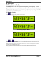
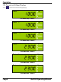
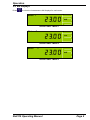
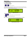
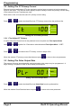
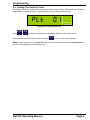
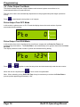
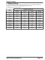
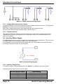
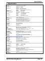
PowerRail 310 Operating Manual February 2010 Safety 1 Safety This instruction sheet gives details of safe installation and operation of the Rail310 electricity meter. Safety may be impaired if the instructions are not followed. Labels on each meter give details of equipment ratings for safe operation. Take time to examine all labels before commencing installation. Safety symbols on the meter have specific meanings. Refer To User Manual Risk of Electric Shock WARNING The meter contains no user serviceable parts. Installation and commissioning should only be carried out by qualified personnel Further information is available at http://www.ndmeter.co.uk. Page 2 Rail310 Operating Manual Operation 2 Operation 2.1 Three Meters in One Box The Rail310 consists of three multi-function electricity meters in a single enclosure. The unit independently monitors up to three single-phase loads providing a clear digital displays of kW, kWh, volts and amps. Three pulse outputs are also available allowing each kWh register to be remotely monitored/logged. An RS485 Modbus RTU serial communications link may be optionally fitted providing multi-function meter readings to remote SCADA systems. 2.2 Energy Displays Press to select the kWh register for each meter. Meter 1 kWh Active Energy Register - Meter 1 Meter 2 kWh Active Energy Register - Meter 2 Meter 3 kWh Active Energy Register - Meter 3 and together and hold for 2 seconds to simultaneously reset the three kWh Press registers, if this feature is enabled. Scaling of the energy registers is set by the nominal input currents and voltages and remains constant during operation of the meter. Energy registers will each accumulate from zero to 99,999,999 then restart from zero. Rail310 Operating Manual Page 3 Operation 2.3 Current and Voltage Displays Press to select from the following displays; Meter 1 A True RMS Amps - Meter 1 Meter 2 A True RMS Amps - Meter 2 Meter 3 A True RMS Amps - Meter 3 Meter 1 V True RMS Volts - Meter 1 Meter 2 V True RMS Volts - Meter 2 Meter 3 V True RMS Volts - Meter 3 Page 4 Rail310 Operating Manual Operation 2.4 kW Displays Press to select the instantaneous kW displays for each meter. Meter 1 kW Active Power - Meter 1 Meter 2 kW Active Power - Meter 2 Meter 3 kW Active Power - Meter 3 Rail310 Operating Manual Page 5 Operation 2.5 Pulse Outputs Three isolated pulse outputs are provided for connection to external systems such as Building Energy Management Systems (BEMS), data loggers, remote counters etc. Pulse 1 is associated with the active energy (kWh) register of Meter 1, Pulse 2 with Meter 2 and Pulse 3 with Meter 3. A single pulse occurs for each unit of energy on the display (eg 1 pulse per 0.1kWh). The pulse rate (amount of energy associated with each pulse) and pulse length is programmable and may be set to suit the external system. Pulse outputs take the form of a volt free contact closure. Pulse 1 provides a momentary short circuit between contacts C and P1 each time Meter 1 kWh register increments a set number of times. Pulse 2 provides a momentary short circuit between contacts C and P2 each time Meter 2 kWh register increments a set number of times. Pulse 3 provides a momentary short circuit between contacts C and P3 each time Meter 3 kWh register increments a set number of times. 2.5.1 Pulse LED A Light emitting diode (LED) on the front panel of the instrument remains ON during each output pulse of the meter, which is currently shown on the LCD. Pulse Output Indicator Page 6 Rail310 Operating Manual Programming 3 Programming 3.1 Programming Menu To enter programming mode: Hold and together for 5 Seconds. A Security Code may be required before changes to programmed parameters are allowed. This is only required if a Security Code greater than zero is set via serial communications. This is then stored in non-volatile memory during power interruptions. 4-Digit Security Code To Enter the Security Code: Press or Press to select next most significant digit. to change each digit. (Lowest significant digit first). When a valid code is entered, the first page of the programming menu is displayed. A Programming Menu First Page Rail310 Operating Manual Page 7 Programming 3.2 Setting The CT Primary Current External current transformers (CTs) are required to reduce large currents to a level accepted as inputs to the meter. The Rail310 meter displays require scaling to match the primary current rating of the external Current Transformers used. Each meter in the unit uses the same CT primary current rating. Press or to select the Next/Previous CT Primary current from the preferred list. A Setting The CT Primary Current 3.2.1 Fine Adjust CT Primary If values other than those found in the preferred list are required use Fine Adjust Mode: Hold and Press or together for 2 Seconds to select/deselect Fine Adjust Mode “CTF”. to increment the CT Primary current in steps of 5A. When the desired CT primary current has been set press to move to the next parameter. 3.3 Setting The Pulse Output Rate The amount of energy associated with each momentary pulse output may be programmed. A single setting is required to scale all three Meter pulse outputs. kWh Setting The Pulse Output Rate Press or to select the Next/Previous Pulse Rate from the preferred list. When the desired Pulse Rate has been set press to move to the next parameter. Page 8 Rail310 Operating Manual Programming 3.4 Setting The Pulse On Time The length of time (in seconds) each momentary pulse output remains “ON” (short circuit) may be programmed. A single setting is required to scale all three Meter pulse outputs. Setting The Pulse Output Rate Press or to select the Next/Previous Pulse On Time from the preferred list. When the desired Pulse Rate has been set press to move to the next parameter. Note: When selecting a long Pulse On Time it may be necessary to reduce the Pulse Rate to prevent pulses appearing permanently “ON”. Rail310 Operating Manual Page 9 Programming 3.5 Pulse Output Test Mode This feature allows the pulse output hardware and external system connections to be commissioned without a measured load. The test pulse rate is set automatically dependant on the programmed pulse length (maximum 0.5Hz). Press to start/stop the test pulses on all outputs. Pulse Output Test OFF Mode In this mode no pulses occur on P1-P3 and the display shows the total number of pulses accumulated during testing: Pulse Output Test RUN Mode In this mode pulses occur simultaneously on all three outputs with an Pulse On Time set in programming mode above. The Pulse Rate is set automatically to be greater than twice the Pulse On Time. The display shows the total number of pulses accumulated during testing Press and together to stop the test pulses and simultaneously reset the test counter. When the test is complete press to move to the next parameter. Note: When selecting a long Pulse On Time it may be necessary to reduce the Pulse Rate to prevent pulses appearing permanently “ON”. Page 10 Rail310 Operating Manual Display Scaling 4 Display Scaling The units, kWh or MWh and the position of the decimal point for the energy/power displays are automatically set dependant on the CT Primary setting for the meter. The display pages are scaled as follows: CT Primary Display Resolution Amps Volts Power Energy <10 A 0.001A 0.1V 0.001kW 0.001kWh =10 A 0.01A 0.1V 0.001kW 0.001kWh <=80 A 0.01A 0.1V 0.01kW 0.01kWh <=100 A 0.1A 0.1V 0.01kW 0.01kWh <=800 A 0.1A 0.1V 0.1kW 0.1kWh <=1,000 A 1A 0.1V 0.1kW 0.1kWh <=8,000 A 1A 0.1V 1kW 1kWh <=10,000 A 0.01kA 0.1V 1kW 1kWh <=25,000 A 0.01kA 0.1V 0.01MW 0.01MWh Rail310 Operating Manual Page 11 Installation 5 Installation 5.1 Mounting On A Rail The Rail310 conforms to DIN 43880, 6-Module Wide. The unit is therefore compatible with a number of standard distribution systems with 45mm cut-outs. The meter should be mounted on a 35mm symmetrical (“Top-Hat”) DIN rail of minimum length 106mm. 5.2 Pulse Output Connection The pulse outputs take the form of isolated volt free normally open contacts. The pulse output circuit is isolated from all other circuits at 2.5kV / 1 minute. The pulses can be used as an input to a remote counter, pulse logger, building energy management system etc. Pulse Output Connections Page 12 Rail310 Operating Manual Standard Connections 6 Standard Connections 6.1 Measurement Input Connections Meter 1 Measurement Input Connections Meter 2 Measurement Input Connections Meter 3 Measurement Input Connections Rail310 Operating Manual Page 13 Standard Connections Meters 1-3 With Common Voltage Input 6.1.1 Voltage Measurement Input Fuses It is recommended to fit a fuse/circuit-breaker to each voltage measurement input. This allows the Rail310 to be isolated should maintenance be required. Each meter voltage measurement input takes less than 1mA at nominal 230V. Recommended fuses should be rated at 250V / 100mA (Type T). 6.1.2 Common Neutral The voltage measurement inputs must be sourced from a supply with a common neutral point. Suitable circuits include; several feeders off a single-phase circuit or individual phases of a 3phase 4 wire supply. 6.2 Auxiliary Meter Supply The Rail310 requires an ac supply to power the measurement circuit and display. This can be any ac supply meeting the specification stated on the units rating label. It is acceptable to cross connect the meter supply with one of the voltage measurement inputs providing the specified ratings are not exceeded. Rail310 Unit Auxiliary Supply 6.2.1 Auxiliary Supply Fuse The auxiliary supply is not fused internally in the Rail310. An external fuse must be fitted. External Auxiliary Supply fuses should be rated: Page 14 No of Rail310 Units Fuse Rating 1-10 11-20 20-50 >50 250V / 500mA Anti-Surge 250V / 1A Anti-Surge 250V / 2.5A Anti-Surge Use multiple fuses as above Rail310 Operating Manual Specification 7 Specification INPUTS System Voltage Un Current In Measurement Range Frequency Range Burden Overload 3 Loads with a common neutral Standard: 3 x 230Vac Optional: 3 x 120Vac Standard: 5A from external CTs. Optional: 1A from external CTs. Optional: 0.333V from external current sensors Voltage 50% to 120% Current 0.2% to 120% Fundamental 45 to 65Hz Harmonics Up to 30th harmonic at 50Hz Voltage <0.1VA per meter Current <0.1VA per meter Voltage x2 for 1 hour Current x20 for 0.5 second max DISPLAY Type Data Retention Format Scaling Legends Custom, Supertwist, LCD 10 years min. Stores kWh & Meter set-up 8 x 9mm high digits with DPs & 2.8mm legends Direct reading. User programmable CT CT Primary programmable from 5A to 25,000A kWh, MWh etc. depending on user settings AUXILIARY SUPPLY Standard Options Load Overload 230V 50/60 Hz ±15% 115V 50/60 Hz ±15% 2VA max. x1.2 continuous ACCURACY All errors ± 1 digit kWh kW Amps & Volts PF (Modbus Only) Better than Class 1 per EN 62053-21 & BS 8431 Better than Class 0.25 IEC 60688 Class 0.1 IEC 60688 (0.01In – 1.2In or 0.1Un – 1.2Un) ±0.2° (0.05In – 1.2In and 0.2Un – 1.2Un) PULSE OUTPUTS Function Pulse Rate Pulse On Time Rise & Fall Time Type Contacts Isolation 1 Pulse per unit of energy Settable between 1 & 1000 counts of kWh register 0.1 sec. default; Settable between 0.1 and 20 sec < 2.0ms N/O Volt free contact. Optically isolated BiFET 100mA ac/dc max., 100V ac/dc max: 0.5W Max Load 2.5kV 50Hz 1 minute MODBUS® Serial Communications (Optional) Bus Type Protocol Baud Rate Address Latency Command Rate RS485 2 wire + 0v. ½ Duplex, ¼ unit load MODBUS® RTU with 16 bit CRC 4800, 9600 or 19,200 User settable 1 – 247 User settable Reply within 250ms max. New command within 5ms of previous one GENERAL Temperature Humidity Environment Operating -10°C to +55°C Storage -25°C to +70°C < 75% non-condensing IP20 MECHANICAL Terminals Enclosure Material Dimensions Weight Rising Cage. 4mm2 (12 AWG) cable max. DIN 43880, 6-Modules Wide Noryl® with fire protection to UL94-V-O. Self extinguishing 106 x 90 x 58mm (Cut out 106 x 45mm) ~ 250 gms SAFETY Conforms to EN 61010-1 Installation Category III Rail310 Operating Manual Page 15