1
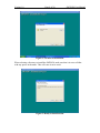
SMT6050
User Manual
Sundance Digital Signal Processing Inc
4790 Caughlin Parkway #233
Reno, NV 89509-0907
U.S.A
+1 (775) 827-3103
Sundance Multiprocessor
Chiltern House
Waterside
Chesham
HP5 1PS
United Kingdom
+44 (0)1494 793167
This document is the property of Sundance and may not be copied nor communicated to a
third party without the written permission of Sundance.
© Sundance Digital Signal Processing Inc. 2005
Version 1.0
Page 2 of 20
SMT6050 User Manual
Revision History
Date
4-20-2005
Comments
Initial Release
Engineer
R.N
Version
1.0
Version 1.0
Page 3 of 20
SMT6050 User Manual
Table of Contents
Chapter 1............................................................................................................................. 5
Introduction..................................................................................................................... 5
Simulink.......................................................................................................................... 5
Chapter 2............................................................................................................................. 6
Supported Hardware ....................................................................................................... 6
Software Requirements................................................................................................... 6
Chapter 3............................................................................................................................. 7
Installation....................................................................................................................... 7
Chapter 4........................................................................................................................... 11
Related Documents ....................................................................................................... 11
Support.......................................................................................................................... 11
Library........................................................................................................................... 12
Chapter 5........................................................................................................................... 13
Demos ........................................................................................................................... 13
Version 1.0
Page 4 of 20
SMT6050 User Manual
Table of Figures
Figure 1 Library ................................................................................................................ 12
Figure 2 Matlab Window .................................................................................................. 14
Figure 3 Parameters .......................................................................................................... 14
Figure 4 Build project ....................................................................................................... 15
Figure 5 System Target File.............................................................................................. 15
Figure 6 Code Composer Studio Window ........................................................................ 16
Figure 7 Real and FFT Graph ........................................................................................... 17
Figure 8 Real and FFT Graph ........................................................................................... 18
Figure 9 Matlab Demo Window ....................................................................................... 19
Figure 10 Demodspcop results window............................................................................ 19
Version 1.0
Page 5 of 20
SMT6050 User Manual
Chapter 1
Introduction
SMT6050 is the Matlab® and Simulink® toolbox for all of Sundance’s hardware. It
provides the customer with the flexibility of working in the Simulink® environment. This
will speed up the development time of many systems since there is no code needed for
the Sundance hardware.
Simulink
Simulink® is a simulation and prototyping development tool for modeling, simulating,
and implementing real-world dynamic systems. Data acquisition, environment control
and processing power provided by Sundance products as the front-end of any system is
complemented by Simulink® to build, easy to develop and maintain, target applications.
User interface is in a form of block diagrams that are intuitive and easy to understand.
Building of blocks and interconnections between them defines a data flow, type of
processing and in final stage the customer’s algorithm and system. This technology
generates optimized C code for your application and compiles it into a binary format for
further downloading to the Sundance products. Code Composer Studio provides a
complete project management environment.
Version 1.0
Page 6 of 20
SMT6050 User Manual
Chapter 2
Supported Hardware
SMT335
SMT335E-1000
SMT335E-2000
SMT361
SMT365
SMT365E
SMT365G
SMT374-6713-2
SMT375
SMT375E-1000
SMT375E-2000
SMT376-6711-128
SMT376-6711-256
SMT395-VP20-5
SMT395-VP30-6
Software Requirements
Software
Processors
Disk Space
RAM
Matlab v14/14.1
Simulink
RTW
Pentium III, IV,
Xeon, Pentium M,
AMD Athlon,
Athlon XP, Athlon MP
400MB
CCS 2.2 (3.0)
233MHz or higher
630MB
256MB
SMT6050
233MHz or higher
20.5MB
128MB
256MBMin
512MB
(Recommended)
Version 1.0
Page 7 of 20
SMT6050 User Manual
Chapter 3
Installation
************************************************************************
When installing SMT6050 please don’t install to any folder with spaces. Therefore the
user should not install to the ‘Program Files’ folder. The same thing goes with Code
Composer studio. Matlab has trouble dealing with spaces.
************************************************************************
Figure 1: First page
Version 1.0
Page 8 of 20
SMT6050 User Manual
Figure 2: Location of installation
When selecting a directory to install the SMT6050, make sure that it is not to a folder
with any spaces in the name. This will cause it not to work.
Figure 3: Ready to install section
Version 1.0
Page 9 of 20
Figure 4: Installation complete
SMT6050 User Manual
Version 1.0
Page 10 of 20
SMT6050 User Manual
Configuration
In the command window type SundanceOptions and the following screen will appear.
This will allow the user to set up the SMT6050.
Figure 5: Configuration window
Compiler options: These are compiler options, which will be passed to C6X during
compilation. For more information please consult Code Composer
Studio documentation.
Linker Options:
These options will pass to the linker during linkage phase. For more
information please consult Code Composer Studio documentation.
Sundance Board: This section allows the user to select which board is being used so
therefore which type of DSP the code is being written for.
RTOS:
At the moment the only option available is for Bare Board systems.
TI root:
The user must specify the directory of the TI Code Composer studio
root folder in this section.
The SMT6050 is now installed and fully configured.
Version 1.0
Page 11 of 20
SMT6050 User Manual
Chapter 4
Related Documents
Matlab Release 14.2 Data Sheet
Simulink Version 6.0 Data Sheet
Real Time Workshop (v5)
Code Composer Studio User Guide
SMT6012 Manual
SMT6025 Manual
Support
Please register on the Sundance Support Forum if not yet registered. Then enter your
company’s forum and request the support you need for the desired product. You may also
contact us at [email protected].
To reach us by telephone you can call +1(775) 827-3103 for Sundance DSP, or +44
(0)1494 793167 for Sundance Multiprocessor, or +39 0185 385193 for Sundance Italia.
Version 1.0
Page 12 of 20
SMT6050 User Manual
Library
SMT6050 provides all the blocks needed for creating code that runs on any of the
Sundance DSPs. To see the library within SMT6050 the user must type ‘Simulink’ in the
command window. The following screen will open:
Figure 1 Library
With these different blocks the user can design a system, which can be easily debugged
due to the graphical interface of Simulink®.
Version 1.0
Page 13 of 20
SMT6050 User Manual
Chapter 5
Demos
SMT6050 comes with four demos’ to help illustrate the process of designing a system
and how the final C code is generated.
These demos run on an SMT365, SMT370 and an SMT310Q.
The connections are as follows:
1. FMS between T1C0 and T2C3
2. Connect SHB A on SMT365 to SHB A on SMT370 via SMT516 or SHB Cable
3. Connect SHB B on SMT365 to SHB B on SMT370 via SHB Cable
4. Connect J10 to J12 and J9 to J13 on the SMT370
There are 3 demos for 3 types of applications:
1- Data acquisition and processing. In this demo, SMT 370 is used to generate a
pattern with DAC and then capture it with ADC. The FFT of a captured signal is
then calculated and sent to the PC to display in real time. Only one ADC channel
is used for this purpose since the other channel is the same.
2- DSP coprocessor. In this demo, the DSP board is used as a DSP coprocessor for
Matlab. Applications in Matlab send data to DSP board for fast processing. In the
demo, a signal is generated in Matlab and sent to the DSP. In the DSP the FFT of
this signal is calculated and returned back to Matlab. Matlab shows the signal and
its FFT.
3- Hardware in the Loop. In this application, some sections of the simulation are
done in the PC and some other section is done in DSP. In this demo, a
Microphone and PC speaker is used for signal capturing and DSP processes them.
All of the demos are saved under the Demo subdirectory.
C:\Sundance\demos
Data acquisition Demo:
This demo is under 370_realtime subdirectory.
There are 3 files there:
1- Demo370dsp.mdl: Simulink model for code generation.
2- Demo370.m: Matlab code for displaying captured data in real-time.
3- Demo370.fig: GUI for Matlab code.
Running the demo:
Version 1.0
Page 14 of 20
SMT6050 User Manual
1- Start Matlab.
2- In the Matlab command window, change the directory to the 370_realtime
directory.
cd C:\ Sundance\demos\370_realtime
Or at the top of the Matlab window there is a tab that says current directory. The
directory can be changed there rather than typing the address each time.
3- Type open demo370dsp.mdl in Matlab command window. The following window
should appear:
Figure 2 Matlab Window
4 - Double click on smt370. The following dialogue box will appear.
Figure 3 Parameters
4- Make sure that the path to pattern File is correct and pattern file is available.
5- From this window menu, select: Simulation-> configuration parameter
Version 1.0
Page 15 of 20
SMT6050 User Manual
6- The following windows should appear:
Figure 4 Build project
7- In the ‘RTW system target file’ select browse and then select ‘Sundance.tlc’ so
that the code will be generated for Sundance hardware.
8- Press ‘Generate code’.
Figure 5 System Target File
9- After Matlab is done creating the code the user will have to start up Code
Composer and add the created code.
Version 1.0
Page 16 of 20
SMT6050 User Manual
Figure 6 Code Composer Studio Window
10- Load the code into the DSP board File->load program
11- Run the program: Debug->Run
12- Make sure that the model is started by looking for the following message in CCS:
“Model Started “
13- Select Matlab window and type: open 370demo.m
14- The following window should appear:
Version 1.0
Page 17 of 20
SMT6050 User Manual
Figure 7 Real and FFT Graph
15- Don’t change Frame Size from 128! It is for further development!
16- Press start.
17- Real data should appear in the two graphs. The upper graph is the captured signal
and the lower graph is its FFT.
Version 1.0
Page 18 of 20
SMT6050 User Manual
18- The capturing stops after a little while. To start again, press Start.
Figure 8 Real and FFT Graph
DSP coprocessor:
The object of DSP coprocessor is that the user sends time-consuming operations to DSP
for fast processing. In this example, the DSP does FFT and sends the result back to
Matlab.
There are 3 files in this demo:
1- DemoDSPcopDSP.mdl : the model for code generation.
2- DemoDSPcop.m Matlab program
3- DemoDSPcop.fig GUI for Matlab program.
Running the demo:
1- Run Matlab and change the Matlab directory to Dsp_cop.
2- Cd C:\ Sundance\demos\dsp_cop
Version 1.0
Page 19 of 20
SMT6050 User Manual
3- Type in: Open demodspcopdsp.mdl
Figure 9 Matlab Demo Window
4- Generate code for it (simulation->configuration parameter and …)
5- Compile code, load it and run the code (in CCS)
6- Type open DemoDSPCop.m in Matlab window:
Figure 10 Demodspcop results window
Version 1.0
Page 20 of 20
SMT6050 User Manual
7- Press calculate. The data related to the function that you entered is calculated and
sent to DSP, the DSP calculates the FFT and returns the result for displaying.
Something that you can do with this demo:
1- Change the function. The function is any valid Matlab function with t as the
variable. For example the followings are valid functions:
• t
• t+100
• Sin (t *100)
Some interesting functions are:
• 2^12 *sin ((t-500)/20)
• 2^12 *sin (t/5)*(1+0.8*sin (t/50))
• 2^12 *sin (t/5 + 2 * pi * sin (t /50))
Demo Hardware in the loop.
In this demo, some section of the demo is running in the PC and some other section is
running in the DSP.
This demo has 3 files:
1- Mic.mdl: The model for PC section that uses a microphone as input
2- File.mdl: The model for PC section that uses a file as input.
3- Reverb.mdlTthe model that should be run in the DSP.
Running the model:
If you have a full duplex sound card and a good microphone use mic.mdl otherwise use
file.mdl.
12345-
Open Matlab and change its directory to hardware_in_the_loop directory.
Open reverb.mdl and generate code for it.
Compile, load and run into the DSP with CCS.
Open Mic.mdl or file.mdl.
From its window select simulation->start and then speak into the mic (or listen to
the speaker if you are using file version).