1
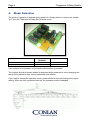
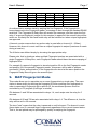
Fingerprint
4-Relay Module
Art. No.: 460186
User's Manual
FP4Relayv.1 User Man. ENGdec11
Conlan ApS - Speditorvej 2A - DK-9000 Aalborg - Tlf.: +45 7240 6003 - Fax: +45 9632 0022
www.conlan.eu - [email protected]
Page 2
Fingerprint 4-Relay Module
Table of Contents
Page
1.
2.
3.
4.
5.
6.
7.
8.
9.
Introduction ........................................................................................3
Electrical Connections ....................................................................3
Communication Parameters ..........................................................3
Mode Selection ..................................................................................4
Fingerprint Reader Association (learning mode). ...................5
Startup Messages & Log Output ..................................................5
6.1 Boot message ........................................................................6
6.2 Messages during Normal Operation ...............................6
Limitations ..........................................................................................6
7.1 Other Devices ........................................................................6
N-factor Authentication Mode (verify different fingers within 120 sec)...........6
MAP Fingerprint Mode (verify different fingers to different access) ....................7
User's Manual
1.
Page 3
Introduction
The Fingerprint 4-Relay Box enables you to control up to 4 relay using 4 or more distinct
fingerprints.
The fingerprint 4-Relay Box comes preconfigured, and there's no need to further
configuration by PC or other configuration software.
The Fingerprint 4-Relay Box has 2 jumper selectable modes of operation; "N-factor
authentication" and "Map Fingerprint authentication".
2.
Electrical Connections
The Fingerprint 4-Relay Box needs only 12 V DC and communication/data connections.
The power supply must be connected to terminals 12V and 0V. Ensure, that the polarity is
correct before powering on the device.
Communications is established by connecting the blue wire from the Fingerprint reader to
terminal "B". The orange wire must be connected to terminal "A".
The maximum power consumption is 100mA (when all relays are set).
3.
Communication Parameters
The Fingerprint reader must be configured with the correct communication parameters.
Normally this has already been done during production. However, if you experience
communication problems make sure, that the Fingerprint reader communication
parameters are set up for:
9600 BAUD
8 databits
No Parity
1 stop bit
Page 4
4.
Fingerprint 4-Relay Module
Mode Selection
The mode of operation is defined during power-on. Simply attach or remove the Jumper
"jp1" from the Fingerprint 4-Relay Box to select mode:
Mode
Jumper removed Jumper attached
(default)
N-factor authentication
X
Map Fingerprint authentication
X
If the Jumper is not present, only N-factor authentication is possible.
The Jumper should be remain seated or detached while powered on, since changing the
setup during operation may cause undesirable side effects.
If you wish to change the operation mode, power off the device and change the Jumper
setting. When the unit is powered back up, the operation mode is changed.
User's Manual
Page 5
5. Fingerprint Reader Association (learning mode)
You may decide to connect multiple Fingerprint readers to the same communication bus
(RS485). In this case, each Fingerprint reader should have an unique module ID in order
to communicate unambigiously.
If you need to associate a Fingerprint 4-Relay Box with one or more Fingerprint readers,
you may do so by setting the Fingerprint 4-Relay Box in learning mode.
Learning mode is set by attaching Jumper 2 pin 1 + 2 before powering on the Fingerprint
4-Relay Box. When powering on the learning mode, previously learned module ID's are
erased.
It is currently possible to associate up to 128 module ID's (Fingerprint readers) with a
single Fingerprint 4-Relay Box. Please note, that this number is likely to be reduced to
32 modules in future versions.
When all ID's has been added/learned, you should remove power and then remove
Jumper 2 before applying power.
6.
Startup Messages & Log Output
Under certain circumstances human readable strings (US-ASCII) are sent to the data bus.
These strings are readable using a standard serial-terminal application such as Hypercom,
Putty or Realterm. For Windows we recommend Putty (http://www.putty.org/) and for other
operating systems Putty or Minicom (http://freshmeat.net/projects/minicom/).
Page 6
Fingerprint 4-Relay Module
6.1 Boot message
When booting, the Fingerprint 4-Relay Box will print out (send data to the communication
bus) version info.
FPRELAY 1.6
[MODE] mode ([STATE])
where [MODE] is either "Unique FP" or "Map FP" depending on Jumper 1 setting and
[STATE] is either "work" or "learn" depending on Jumper 2 setting.
6.2 Messages during Normal Operation
Each time a valid fingerprint is processed, the corresponding fingerprint ID is sent to the
bus. The format is
"Userid: number"
where number is a 6-digit integer. In case the number requires fewer digits, the number is
prepended with 0's (zeroes) until the number string is 6 digit wide.
7. Limitations
7.1 Other Devices
The Fingerprint 4-Relay Box has been tested in conjunction with Fingerprint readers and
Fingerprint reader configuration software. If you decide to connect other devices to the
same communication bus, please be aware, that undesired side effects may arise.
8. N-factor Authentication Mode
N-factor authentication (or Multi-factor authentication) means using any independent twofour fingerprints to increase the assurance that the bearer has been authorized to access
secure areas or systems.
The factors (fingerprints) may be associated with several individual bearers. That is, using
the Fingerprint 4-Relay Box you may define a system, which only allows access if more 24 individual persons grants access by swiping their fingerprint.
User's Manual
State
IDLE
State 1
State 2
State 3
State 4
Page 7
Relay 1
off
on
on
on
on
Relay 2
off
off
on
on
on
Relay 3
off
off
off
on
on
Relay 4
off
off
off
off
on
Authentication
N/A
1-factor
2-factor
3-factor
4-factor
An authentication session starts by swiping the first fingerprint. If the fingerprint is
known/approved to the Fingerprint reader, a message is sent through the standard RS485
serial bus. The Fingerprint 4-Relay Box will receive the message, and then open the first
relay. If a second fingerprint (unique for this session) is approved, the second relay will be
switch on. Similarity the third and fourth relay will be switched on when unique fingerprints
are approved.
A timeout counter ensures that any active relay is reset after a timeout (t1~120sec).
However, this timeout is reset each time a unique fingerprint is swiped (maximum 4 resets
during a session).
The N-factor can defined simply by choosing the appropriate relay.
Please note, that in situations where multiple Fingerprint readers are associated with a
single Fingerprint 4-Relay Box, each Fingerprint reader should have the same mapping of
fingerprint ID's.
For example if a person's fingerprint is stored at position 20 on the first Fingerprint reader
and position 34 in the second Fingerprint reader, this person will be able to perform
successful 2 factor authentication. If the fingerprints are stored at the same position the
Fingerprint Relay Box will ignore the second input.
9. MAP Fingerprint Mode
This mode allows you to associate one or more fingerprints to a single relay. The association is done simply by defining the fingerprint ID when enrolling new fingerprints. In
order to associate a fingerprint with a specific ID, the enrollment process must be
controlled by a PC program (UniFinger or similar).
ID's between 0 and 399 are associated to relays 1-4, each swipe sets the relay for 5
seconds.
ID's between 400 and 799 are also associated with relays 1-4. The difference is, that the
relay will be set for 30 seconds.
The term "sets" means that the relay is powered on until a timeout. The timeout is reset
(timer starts over) if a second finger is approved regardless of the current timeout status.
That is, the set-period may be prolonged by quickly re-swiping the fingerprint.
Finally ID's 800-999 are used for toggling relay 3 and 4. That is, approved fingerprints
stored with ID 800-899 toggles relay 3 each time a fingerprint is swiped. If relay was
previously on, the relay will be turned off. If the relay is turned off, toggling will set the
relay on.
The relay mapped to fingerprint ID's 200-299 & 600-699 overlaps fingerprints mapped
to ID's 800-899 (relay 3). Similar the ID's 300-399 & 700-799 overlaps fingerprints
mapped to 900-999 (relay 4);
When ID's 800-899 are recognized, the corresponding relay will change state
regardless of previously swiped fingerprints.
When ID's 200-299, 600-699 or 300-399, 700-799 are recognized, the corresponding
relay will be set (turned on) and later turned off according to previously defined timeout values regardless of previously read fingerprints.
Fingerprint
position
0-99
100-199
200-299
300-399
400-499
500-599
600-699
700-799
800-899
900-999
Relay 1
Relay 2
Relay 3
Relay 4
5 sec
N/A
N/A
N/A
30 sec
N/A
N/A
N/A
N/A
N/A
N/A
5 sec
N/A
N/A
N/A
30 sec
N/A
N/A
N/A
N/A
N/A
N/A
5 sec
N/A
N/A
N/A
30 sec
N/A
Toggle
N/A
N/A
N/A
N/A
5 sec
N/A
N/A
N/A
30 sec
N/A
toggle
Table 1
Thank you for choosing Conlan's products.
Please contact our support service for further
information whenever needed.
Conlan ApS - Speditorvej 2A - DK-9000 Aalborg - Tlf.: +45 7240 6003 - Fax: +45 9632 0022
www.conlan.eu - [email protected]