1
Tranax 1700w
Operator Manual
Table of Contents
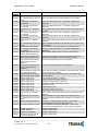
TABLE OF CONTENTS
1. INTRODUCTION
1.1 Features
1.1.1 About the Tranax 1700w™
1.2 Specifications
Tranax 1700w™ Specifications
1.2.1 Dimensions and Component Locations
1.2.2 LCD & Customer Keypad
1.2.3 Cash Dispensing Unit
1.2.4 Receipt Printer
1.2.5 Main Control Board
1.2.6 Operating Environment
1.3 Warranty/Service
2. INSTALLATION
2.1 Tranax 1700w™ Installation
2.1.1 Unpacking
2.1.2 Physical Installation
2.1.3 Hardware Setup
3. PROGRAMMING
3.1 Initial Setup
3.1.1 Accessing the Operator Function Menu
3.1.2 When An Error Occurs
3.1.3 EPP Keypad
3.2 The Host Setup Menu
3.2.1 Key Management
3.2.2 Set Host Telephone Number
3.2.3 Set Terminal ID Number
3.2.4 Health Check Message
3.2.5 Connect Timer
3.2.6 Remote Monitor
3.2.7 Trial Day Total
3.2.8 Host Processor Mode
3.3 The System Setup Menu
3.3.1 Set Clock
3.3.2 ISO 1,2,3 En/Disable
3.3.3 Optional Languages
3.3.4 Change Passwords
3.3.5 Modem Setup
3.3.6 Modem Test
3.3.7 RMS Ring Count
3.3.8 Serial Number
3.4 Customer Setup Menu
3.4.1 Change Message
3.4.2 BIN Lists
3.4.3 Optional Function
3.4.4 Surcharge Mode
3.4.5 Advertisements
1700w
(Rev 1)
© Tranax 2009 – Do Not Distribute
Operator Manual
Table of Contents
Operator Manual
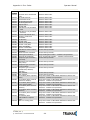
3.5 Transaction Setup
3.5.1 Dispense Limit
3.5.2 Denomination
3.5.3 Fast Cash
3.5.4 Low Currency Check
3.6 TCP/IP Setup
4. OPERATION
4.1 Opening and Closing
4.1.1 Opening the Security Door
4.1.2 Closing the Security Door
4.1.3 Opening the top Bezel
4.1.4 Closing the top Bezel
4.1.5 Operating and Changing the Combination Lock
4.1.6 Operating and Changing the Electronic Lock
4.2 Cash Operations
4.2.1 Adding Cash to the Cassette (TCDU)
4.2.2 Emptying the Reject Bin (TCDU)
4.2.3 Adding Cash to the Cassette (MCDU)
4.2.4 Emptying the Reject Bin (MCDU)
4.2.5 Loading the Receipt Printer
4.3 Settlement Menu
4.4 Journal Menu
4.5 Reports Menu
5. DIAGNOSTICS
5.1 Diagnostics Menu
6. CUSTOMER TRANSACTIONS
6.1 Opening Procedure
6.2 Withdrawal Transaction
6.3 Balance Inquiry Transaction
6.4 Transfer Transaction
6.5 Closing Procedure
6.6 Error Recovery
APPENDIX
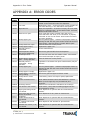
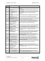
A. Error Codes
B. Pin Pad layout for Master Key / Download Mode / Clear NVRAM
C. TDES Master Key installation
D. Graphic Advertisements
E. CDU Preventative Maintenance
1700w
(Rev 1)
© Tranax 2009 – Do Not Distribute
Introduction
Operator Manual
Tranax 1700w™
1.1 FEATURES
1.1.1 ABOUT THE Tranax 1700w™
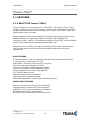
Tranax introduces the next generation in retail ATMs. The Tranax 1700w™ raises
the bar for quality, engineering and design. Built with the philosophies of durability,
reliability and security you’ve come to expect from Tranax, the 1700w™ offers the
absolute best value in its class.
While targeted for lower volume markets, the small footprint design retains all the
standard features of a higher end machine including: Triple DES and ADA
compliance, VISA / Interac / PCI certified encrypting PIN pad (EPP), a voice guidance
system, 56K modem and an integrated lighted topper sign.
Weighing in at over 200lbs, the solidly constructed UL291 Listed – Business Hour
vault provides security and offers the same modular construction for ease of
maintenance.
H/W FEATURES
UL 291 Business Hour Service Vault featuring reinforced steel bottom & dial lock
7” high-resolution, wide-screen TFT LCD
56K modem + Ethernet TCP/IP with SSL encryption
800 note fixed cassette dispenser (TCDU)
1000 note removable cassette dispenser (SCDU)
1700 note removable cassette dispenser (MCDU)
DIP type magnetic card reader (EMV Optional)
2¼” Thermal receipt printer
Modular design for easy maintenance
Lighted transaction guidance system
Meets ADA Standards for Height, Reach and Keypad layout
FUNCTIONAL FEATURES
Electronic journal stores over 40,000 transactions
Supports English, Spanish and French languages
Availability for 8 on screen advertisement graphics
Detailed average history report feature
On-screen error code descriptions for easy service
1700w
(Rev 1)
© Tranax 2009 – Do Not Distribute
1.1
Introduction
Operator Manual
1.2 SPECIFICATIONS
Tranax 1700w™ SPECIFICATIONS
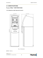
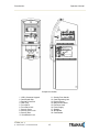
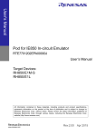
1.2.1 Dimensions and Component Location
Fig. 1 Dimensions
WEIGHT: 206 lbs.
1700w
(Rev 1)
© Tranax 2009 – Do Not Distribute
1.2
Introduction
Operator Manual
Component Location
1. LCD & Customer Keypad
2. Card Reader Slot
3. Receipt Printer Slot
4. Cash Tray
5. Front Panel
6. Front Panel Lock
7. Security Cover
8. Security Cover Lock
9. Security Door
10. Combination Lock
1700w
11. Security Door Handle
12. Cash Dispensing Unit
13. Receipt Printer
14. Main Control Board
15. Ear Phone Jack
16. Power Supply
17. Speaker.
18. ADA Board
19. Card Reader
(Rev 1)
© Tranax 2009 – Do Not Distribute
1.3
Introduction
Operator Manual
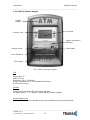
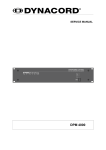
1.2.2 LCD & Customer Keypad
Lighted
Topper
LCD Panel
Function Keys
Lighted Transaction
Guidance
Receipt Printer
Card Reader
Voice Guidance
EPP Keypad
Fig. 3 LCD & Customer Keypad
LCD
Screen Size: 7”
SVGA TFT LCD
Resolution: 320 x 240 QVGA
Display Characters: 40 x 15 (Standard Characters)
8 LCD Function Keys
KEYPAD
Certified VISA compliant EPP (Encrypting Pin Pad)
10 Alphanumeric, 3,4, CANCEL, CLEAR, ENTER, BLANK Keypads
Voice Guidance Port
Voice assisted operation available through the headphone jack on the front bezel
1700w
(Rev 1)
© Tranax 2009 – Do Not Distribute
1.4
Introduction
Operator Manual
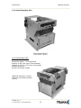
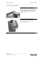
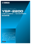
1.2.3 Cash Dispensing Unit
Cash Dispensing Unit
(1000 Note - SCDU)
CASH DISPENSING UNIT
Dispensing Speed: 2.5 notes/second
Capacity of 800 new notes (fixed cassette)
Capacity of 1000 or 1700 notes (removable)
Lockable Reject Bin
Double note detect module
*Optional dispensers include:
1700 note removable cassette
(MCDU)
1700w
(Rev 1)
© Tranax 2009 – Do Not Distribute
1.5
Introduction
Operator Manual
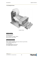
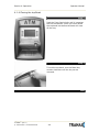
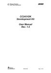
1.2.4 Receipt Printer
Receipt Printer
RECEIPT PRINTER
Thermal line printer
36 characters/line
Semi-automatic roll paper setting
Motorized front push rollers
PAPER SPECIFICATIONS
One sided thermal paper
Factory paper is thermal side out (but either way will work)
6 inch outside diameter roll
2 ¼” inch wide
Core inside diameter 11/16 inch
21# weight (paper thickness)
1700w
(Rev 1)
© Tranax 2009 – Do Not Distribute
1.6
Introduction
Operator Manual
1.2.5 Main Control Board
Intel XScale® 400MHz 32-bit CPU
128MB RAM
WinCE™ Operating System
Modem: 56,000 bps dial-up modem (standard)
TCP/IP Ethernet connection (standard) Onboard SSL (requires activation)
Electronic Journal: 40,000 transactions
Battery back-up for set-up parameters (NVRAM)
Real time clock
1.2.6 Operating Environment
POWER REQUIREMENTS
110/220 VAC ± 10%, 50/60 Hz, 145 Watts
POWER CONNECTIONS
For warranty purposes, the Tranax 1700™ series ATM must be connected to a
dedicated power circuit. This circuit must consist of line, neutral, and ground leads
connected directly to the power circuit breaker panel. This circuit should not be
shared with any other equipment. Use of a surge protector or uninterruptible power
supply is recommended.
PHONE LINE REQUIREMENTS
The Tranax 1700™ series ATM should be connected to a dedicated phone line. This
line must be a direct dial “tone” or “pulse” line that is equipped with a standard
telephone wall jack (RJ-11). This line cannot be shared with any other equipment at
the location. Use of shielded (CAT5) phone cable is recommended for best
performance and to reduce the chance of interference.
TEMPERATURE
In storage
While operating
: 32°F - 123°F (0°C ∼ 49°C)
: 40°F - 95°F (5°C ∼ 35°C)
HUMIDITY
In storage
While operating
1700w
: 10% < RH < 90%, non-condensed
: 15% < RH < 85%, non-condensed
(Rev 1)
© Tranax 2009 – Do Not Distribute
1.7
Introduction
Operator Manual
1.3 WARRANTY/SERVICE
MANUFACTURERS WARRANTY
Tranax Technologies, Inc. provides a limited one-year parts warranty and a limited
30 day labor warranty for the 1700w™ series ATM. Tranax guarantees your 1700w™
ATM to be free from defects in materials and workmanship.
The one-year parts warranty and 30-day labor warranty periods will begin 15 days
from the shipping date.
WHAT IS COVERED:
· Cash Dispensing Unit (CDU) and Cash Cassette
· Receipt printer (SHU)
· LCD module
· Magnetic Card Reader (MCR)
· EPP Keypad
· Power Supply
· Mainboard (CE)
· Lock and locking mechanism **LIMITED 90 DAY WARRANTY**
Dial and Electronic locks will be covered by a limited 90-day warranty provided
the warranty registration card is completed and returned to Tranax within 10
days of installation. Should the lock fail under normal use, Tranax will replace
the lock only. Services required to open the vault and or replace the lock are at
the expense of the ATM owner.
WHAT IS NOT COVERED:
· Power cable and modem cable
· Key lock and key
· Plastic Bezels
· Software upgrade
· Receipt printer jam
· Note jam
· Forgotten password or combination of lock
· Any damages from misuse, improper installation, and vandalism
· Any damages from “brown out” or low power, lightning, or any other ‘acts of God’
Your distributor/dealer may offer an enhanced or extended warranty in addition to
the original manufacturers one-year warranty. Once the manufacturers warranty
has expired, all claims for warranty service must be resolved directly between the
distributor/dealer and the ATM owner.
OBTAINING SERVICE: If you have any problems or questions about your Tranax
ATM, your dealer or distributor is your primary contact for assistance/service. Your
manufacturers warranty is provided through your dealer or distributor.
1700w
(Rev 1)
© Tranax 2009 – Do Not Distribute
1.8
Section 2: Installation
Operator Manual
SECTION 2: INSTALLATION
2.1 Tranax 1700w™ INSTALLATION
2.1.1 UNPACKING
Step 1
Once the ATM is unpackaged, do not discard the packaging materials until you have
verified any shipping damage claim. Contact your distributor immediately if you see
any shipping damage.
Step 2
Verify the contents carefully with the packing list to be sure all items listed are
included. Notify your distributor of any shortages.
2.1.2 PHYSICAL INSTALLATION
To install the Tranax 1700w™ ATM, review the following steps:
Step 1
Place the system on a flat surface. The system has a tendency to tip over if the
surface is over 10 degrees. Be careful when opening the top or bottom of the
machine as it will be off balance.
Step 2
Use the holes in the bottom of the vault to mark and drill the appropriate sized holes
for the anchors you will be using. (Anchors are not included). Tranax does not
recommend a particular size or type of anchor as each installation is different
however maximum anchor diameter is ½
Step 3
Install the anchors into the ground according to the anchor bolts locate sheet (4
places). See manufacturer’s instructions for anchor installation.
Step 4
Place the 1700w™ ATM on top of the anchors.
Step 5
Open the Security cover with the key provided. See page 4.1 for Opening and
Closing instructions.
1700w
(Rev 1)
© Tranax 2009 – Do Not Distribute
2.1
Section 2: Installation
Operator Manual
Step 6
Using the supplied combination (see lock manual for default combination), open the
security Door. This combination should be changed as soon as possible. Refer to
page 4.5 (dial) or 4.7 (electronic) for instructions on opening or changing the lock.
Step 7
After the anchor nuts are in place, according to the anchor holes on the bottom of
the ATM, secure the anchor bolts snugly. Do not over tighten anchors as it may
distort the vault and cause problems with the door linkage.
END
2.1.3 HARDWARE SETUP
Step 1
Verify the power voltage (115/220V) to be used and set the
appropriate voltage on the power supply. Default will be
115V. The default setting should be 115V
Step 2
Verify that the telephone line to be used for the ATM is in proper working order.
Tranax recommends the use of shielded (CAT5) phone line in locations with close
proximity to other appliances.
Step 3
Open the security door and remove any shipping materials and note any warning or
installation instructions. See page 4.1 for assistance.
Use this key (2 included) to
open the top and bottom bezels
Cassette key
(removable cassette)
Cassette key
(fixed cassette)
1700w
(Rev 1)
© Tranax 2009 – Do Not Distribute
2.2
Section 2: Installation
Operator Manual
Step 4
Remove the cash cassette from the box (removable cassette dispensers only). Fill
the cassette or cash drawer with the appropriate amount of notes, and carefully
place it in the Cash Dispensing Unit. Place the appropriate denomination label on the
front of the cassette. See page 4.9 for instruction.
Step 5
Before closing the vault, thoroughly test the combination lock by locking and
unlocking the lock several times. It is much easier to diagnose potential lock
problems before shutting the door.
Step 6
Open the top of the ATM. Place the receipt paper in the Receipt Printer. The paper
prints only on one side (shiny side) always check the roll when you install paper.
Place the roll so that the coated side (shiny side) will be facing up. See page 4.12 for
paper loading instruction.
Step 7
Connect the Power cable and the telephone cable to the appropriate outlets on the
wall. Verify that the AC power outlet is grounded. If you are installing the
illuminated topper, make sure to completely install the power cord into the A/C Out
plug on the power supply. The socket takes an extra push to fully seat the plug.
Step 8
Turn the power on and verify that all systems are operational. If any part on the
system or its programming is not operational, an error code will be displayed. If an
error code is displayed, corrective action will be listed below it. If the error cannot
be corrected, please contact your distributor. If no error code is displayed, enter the
Operator Function Menu and view the Error Summary (see programming section).
END
1700w
(Rev 1)
© Tranax 2009 – Do Not Distribute
2.3
Section 3: Programming
Operator Manual
SECTION 3: PROGRAMMING
3.1 INITIAL SETUP
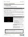
3.1.1 ACCESSING THE OPERATOR FUNCTION
Step 1
To access the Operator Menu, you do not need to hold down the 3 keys (CANCEL,
CLEAR, ENTER) and then press 1 – 2 – 3. Just press the following keys in order
[ENTER] – [CLEAR] – [CANCEL] – [1] – [2] – [3].
Note: The Operator Function menu can only be accessed when the machine is either
in service (“insert your card” screen) or out of service. If the machine is attempting
to connect to the host or initializing, you will not be able to use the key commands to
access the Operator Function Menu.
If you have trouble accessing the Operator Menu, power off the ATM and then either
open the vault door or remove the paper from the printer and power back on. This
will force the ATM to the Operator Menu.
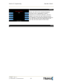
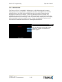
Step 2
Once you successfully completed the key
combination, you will be prompted to enter a
password. There are 3 levels of passwords.
•
•
•
Operator Password (allows access to basic
menu structure)
Service Password (allows access to basic
and diagnostic menus)
Master Password (allows access to all
menus including setup parameters)
You must press ENTER key after typing
the password!
Passwords are very important to maintaining
security for your ATM. Your
dealer/distributor will provide you with
default password information.
WARNING: Tranax Technologies, Inc. highly recommends changing your
passwords from default as soon as possible. Keep all passwords safe and
restrict access to non-authorized personnel.
Passwords MUST be 6 digits in length, use of anything other than a 6 digit
password may cause the passwords to revert back to factory default.
1700w™
(Rev 1)
© Tranax 2009 – Do Not Distribute
3.1
Section 3: Programming
Operator Manual
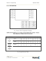
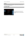
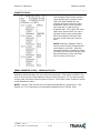
Step 3
Shown the left is the complete Operator
Function menu, depending on which
password you entered (operators, service,
master) you may not see certain functions.
For example, if you use an operator password
you will not see the Host Setup button, as
you will not have access to that menu.
END
1700w™
(Rev 1)
© Tranax 2009 – Do Not Distribute
3.2
Section 3: Programming
Operator Manual
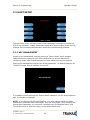
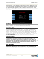
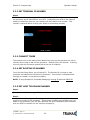
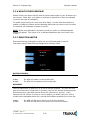
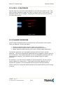
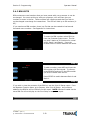
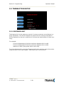
3.1.2 WHEN AN ERROR OCCURS
Step 1
When an error occurs, please press
[ENTER] – [CLEAR] – [CANCEL] – [1] – [2] –
[3].
NOTE: If the machine goes out of service,
the error code will not always appear on the
screen. If you do not see an error code,
enter operator function and go to reports.
Look in the error summary for error codes.
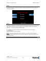
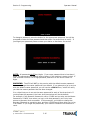
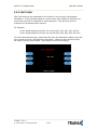
Step 2
“ENTER PASSWORD” will be displayed. Enter
the Master, Service or Operator Password to
continue.
Contact your distributor for default
passwords.
Remember to press ENTER key after
typing password!
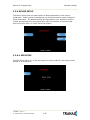
Step 3
When the screen is in current display, press
“OP” key to access the “OPERATOR
FUNCTION.”
END
1700w™
(Rev 1)
© Tranax 2009 – Do Not Distribute
3.3
Section 3: Programming
Operator Manual
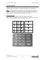
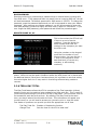
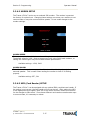
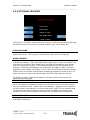
3.1.3 EPP KEYPAD
Fig. 1 Tranax 1700w™ keypad and LCD display
NOTE: LCD Keypads are no longer used for Master Key letters. Please
see addendum included with this manual.
Shift Status
F1
Alphabet
Upper
F5
Number
Special
0
+
=
+
=
0
(
)
Upper
Lower
Number
1
Space
Q
Z
Space
q
z
1
[
]
2
A
B
C
a
b
c
2
{
}
3
D
E
F
d
e
f
3
<
>
4
G
H
I
g
h
i
4
,
.
F3
Alphabet
Lower
Fig. 2 Keypad Character Table
1700w™
(Rev 1)
© Tranax 2009 – Do Not Distribute
3.4
5
J
K
L
j
k
l
5
!
$
6
M
N
O
m
n
o
6
‘
“
7
P
R
S
p
r
s
7
%
*
8
T
U
V
t
u
v
8
:
;
9
W
X
Y
w
x
y
9
?
/
Section 3: Programming
Operator Manual
3.2 HOST SETUP
The Host Setup menu provides access to the parameters necessary to connect the
ATM to the processor. Master Password is required to access most of these options;
however Service password allows basic access for troubleshooting purposes.
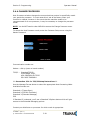
3.2.1 KEY MANAGEMENT
Access to Key Management requires entering a “Secure Mode” which engages
additional security measures (per VISA specification) to prevent Master Key
tampering. Make note of these changes as it does affect how keys are entered.
Entering Key Management requires two 6-digit passwords. By default these will be
“000000” for part #1 and “000000” for part #2.
If a mistake is made entering the “Secure Mode” password, you will be prompted to
wait 30 seconds to reattempt.
NOTE: In compliance with PCI specifications, you must change the Secure Mode
Passwords from default before any Master Keys can be entered. After changing the
Secure Mode Passwords, you must exit completely from the Operator Menu, and
reboot the machine. After this step, you can enter Master Keys.
1700w™
(Rev 1)
© Tranax 2009 – Do Not Distribute
3.5
Section 3: Programming
Operator Manual
Successful entry of both passwords will grant access to the Key Management screen.
From the moment the Key Management area is entered, a 5 minute timer begins. At
the end of 5 minutes, regardless of what you are doing (entering a master key for
example) the Key Management area times out and you will be taken back to the Host
Setup menu.
KEY MODE
This option sets the type of master key you will be loading (TDES, DES, MAC etc.)
Refer to Addendum C for Key Mode descriptions and instructions.
MASTER KEY INDEX
The ATM will hold up to 16 individual Master Keys. Check with your processor to find
if they are expected to be at a certain location. For example Coredata is always
installed at index #9, most other processors are installed at index #0 or #1. The
ATM will only use the key that the index is set to regardless of how many keys are
installed. To set the index simply press the button labeled Master Key Index and
then enter the number you want it set to (enter as a 2 digit number ... 00, 01, 02,
10, 11 etc.) press Enter when done. Press Check Master Key to see a list of
currently installed keys.
CHECK MASTER KEY
This will show the list of available master keys and their appropriate checksums. The
checksum is a 4 digit number calculated from the two 16-digit numbers of your
master key that provides a means to verify the master key is correct. When your
processor provides your Master Keys, they will also give you the 4 digit checksum. If
after entering your Master Key this checksum does not match, try reentering your
master keys or contact the processor.
EDIT MASTER KEY
This is where you enter your two 16-digit Master Keys (provided by your processor).
After pressing Edit Master Key, you will be prompted to enter an index where you
want this key stored. If you do not know which index to use, contact your dealer or
processor. Generally, you should use index 0 or 1 unless otherwise instructed.
1700w™
(Rev 1)
© Tranax 2009 – Do Not Distribute
3.6
Section 3: Programming
Operator Manual
CHANGE PASSWORD
This allows you to set each part of the “Secure Mode” Password. As with the other
passwords used in the 1700w™, each must be a 6 digit number. If you change the
password and cannot remember it, you must clear RAM on the pin pad to reset.
NOTE: In compliance with PCI specifications, you must change the Secure Mode
Passwords from default before any Master Keys can be entered. After changing the
Secure Mode Passwords, you must exit completely from the Operator Menu, and
reboot the machine. After this step, you can enter Master Keys.
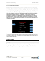
Entering Master Keys:
Use the chart below for entering Master Keys from the main pin pad.
Master Keys (or Key Management) cannot be entered from the optional Rear Service
Panel. Please see Appendix for specific Master Key instructions.
1
4
7
A
1700w™
2
5
8
0
3
6
9
B
(Rev 1)
© Tranax 2009 – Do Not Distribute
3.7
F
E
D
C
Section 3: Programming
Operator Manual
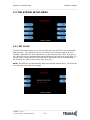
3.2.2 SET TERMINAL ID NUMBER
Step 1
From the Host Setup Menu, go to Terminal ID. Terminal ID number is provided by
the processor and is individual for your ATM. It identifies your ATM on the network
and any transactions done on your machine will be linked to that number. This
number is obtained either through your dealer or processing company.
3.2.3 CONNECT TIMER
The connect timer is the setting which determines how long the machine will wait to
connect when trying to dial into the processor. Default time is 60 seconds. Lowering
this may improve connection speeds but at the risk of reliability.
3.2.4 SET ROUTING ID NUMBER
From the Host Setup Menu, go to Routing ID. The Routing ID is unique to each
processor and identifies the machine by processor. This number is obtained either
through your dealer or processing company.
NOTE: If using Standard 3 (Extended Messaging) Routing ID becomes COMS ID
3.2.5 SET HOST TELEPHONE NUMBER
Step 1
From the Host Setup Menu, go to Telephone Number.
Step 2
You can enter a Primary (Host Phone 1) and a Secondary (Host Phone 2) for the
machine to connect to the processor. These phone numbers are available from your
dealer or the processor (you can also reference the quick installation guide enclosed
with this ATM for numbers for the common processors).
1700w™
(Rev 1)
© Tranax 2009 – Do Not Distribute
3.8
Section 3: Programming
Operator Manual
Step 3
Once you have selected Host Phone #1 or Host Phone #2 you will be prompted with
the following screen. Using the numbers on the keypad press the first number of
your phone number.
Step 4
Tranax always recommends using a dedicated, data-quality phone line for all ATM
installations, however if you are using a phone line that is dialing out through a PBX
type system (where you dial a number for an outside line), then you may insert
commas ( , ) to create a pause between digits.
For example if you have to dial a 9 to get an outside line try the following:
9,,18005551212
(the 800 number being an example)
NOTE: Entering anything other than a number or a comma in the host phone
number field will cause the ATM not to dial out. Make sure that Zero’s and ‘O’s’ are
identified properly.
END
1700w™
(Rev 1)
© Tranax 2009 – Do Not Distribute
3.9
Section 3: Programming
Operator Manual
3.2.6 HEALTH CHECK MESSAGE
Health Check is an option that will send a system status signal to your processor at a
set interval. Check with your dealer or processor to determine if they are prepared
to receive this type of messaging.
To enable simply access the menu from Host Setup. Use the Host Send button to
enable or disable the feature and the Message Send Interval button to set how often
the machine will broadcast its status (in hours).
NOTE: When using Standard 1 processing mode, an option for ‘Extended Health
Check’ will appear. This option is for 4 cassette dispensers and is not used in the
1700w™
3.2.7 REMOTE MONITOR
Remote Monitoring is the ability to dial into your ATM and send or retrieve
information using Tranax Remote Management Software (RMS).
RMS EN/DISABLE
This will allow the ATM to be monitored remotely.
Enable
Disable
The ATM will answer incoming RMS calls.
The ATM will not answer any incoming calls.
RMS SEND
This feature causes the ATM to dial out to a computer running RMS software to
report a malfunction, a fatal error or an out of service condition. Any time the ATM
goes out of service for longer than 3 minutes, it will call the number programmed at
Remote Phone #1 (and then Remote Phone #2 if Remote #1 is busy). It will
attempt this call 3 times. In order to use this feature you MUST have a PC (with a
modem and a dedicated phone line) running RMS software available 24 hours a day.
Enable
Disable
1700w™
The ATM will dial out to report out of service condition.
The ATM will NOT dial out to report out of service condition.
(Rev 1)
© Tranax 2009 – Do Not Distribute
3.10
Section 3: Programming
Operator Manual
RMS PASSWORD
Remote monitoring is protected by a password that is checked when incoming calls
from RMS occur. If the password does not match from an incoming RMS call, the call
will be disconnected. The default password for RMS access is 333333. To change the
password, press the password button and you will be prompted to enter your Master
password. After entering your Master password, you will be prompted to enter the
new RMS password (must be 6 digits) and then enter it again for verification. If you
ever forget the RMS password, press password and follow the procedure again.
REMOTE PHONE #1, #2
This is the number the ATM will call
if there is an out of service
condition. Press the button for
either number and enter the
number for the computer you want
the ATM to call.
Using the numbers on the keypad
press the first number of your
phone number. You can use the <,
> keys on the keypad to move
back and forth (to correct any
mistakes, or edit existing
numbers).
RING COUNT
This setting determines how many rings will elapse before the ATM will answer the
phone. While this can be used in situations where the ATM phone line is shared with
an additional device (like a fax or business phone) it’s important to note that setting
this value higher than 4 or 5 may result in monitoring software being unable to
connect.
3.2.8 TRIAL DAY TOTAL
Trial Day Total feature allows the ATM to complete a Day Total operation (without
actually closing out the machine) at a predetermined time each day. This is useful if
you are doing accounting of your ATM on a day-to-day basis. Your processor cuts off
its transactions each day at a set time. By enabling Trial Day Total at the same
time, your day’s balance should match the host. This information will appear as a
journal record, so you will need to access your journal to print or view the totals.
Your dealer or processor can provide you with the appropriate cut off time.
Trial Day Total Set
Change Time
1700w™
Enables or Disables the function
Sets the time for the ATM to total itself
(Rev 1)
© Tranax 2009 – Do Not Distribute
3.11
Section 3: Programming
Operator Manual
3.3 THE SYSTEM SETUP MENU
3.3.1 SET CLOCK
The Set Clock menu allows you to set the clock built into the ATM to the appropriate
date and time. You should set this for local time in the area the machine is to be
installed. Note that with each transaction you will see also see a “Host” time, this is
the local time for the processor and may be different from local time at the ATM. To
set the clock, simply press the Set Clock button and press the key corresponding to
the function you want to set (month, day, year, etc.)
NOTE: The ATM will not automatically adjust for daylight savings time. You must set
this manually if you wish it to change.
1700w™
(Rev 1)
© Tranax 2009 – Do Not Distribute
3.12
Section 3: Programming
Operator Manual
3.3.2 OPTIONAL LANGUAGES
The Tranax 1700w™ ATM supports 3 on screen languages: English, French &
Spanish. The optional languages will display on the welcome screen, then the
customer will be prompted to choose a language to be used for the rest of that
transaction.
NOTE: The optional languages are displayed on screen only and do not print on the
receipt or journal. Receipts, journals and operator menus are always in English. To
enable or disable a language, simply press the button next to the language you wish
to change.
3.3.3 SPEAKER VOLUME
The 1700w™ speaker volume is adjusted via a screw located on bottom right corner
on the main circuit board (located on the back side of the LCD panel) insert a small
screwdriver into the volume adjustment and turn left (softer) or right (louder).
1700w™
(Rev 1)
© Tranax 2009 – Do Not Distribute
3.13
Section 3: Programming
Operator Manual
3.3.4 ISO 1, 3 EN/DISABLE
The ISO Tracks are the three tracks available for the card swipe head to read. The
ATM is already defaulted to read from Track #2 (which is why it’s not shown). This
parameter should not be changed. Changing the ISO tracks can cause the ATM to
not read cards properly.
3.3.5 CHANGE PASSWORDS
The ATM uses three passwords to provide security to the operator menu system.
These are Operator, Service and Master.
•
•
•
Operator Password (allows access to basic menu structure)
Service Password (allows access to basic and diagnostic menus)
Master Password (allows access to all menus including setup parameters)
The operator password can be changed by anyone with the current operator
password. The service and operator passwords can be changed by anyone with the
service password. The master password can only be changed by someone with the
current master password. Any password can be changed using the master
password.
For example, if you have lost the operator or service password, you can use your
master password to change them. Simply enter the master password when it
requests the operator or service password and then enter the new password.
You are required to change the master password from default before the ATM can go
in service.
1700w™
(Rev 1)
© Tranax 2009 – Do Not Distribute
3.14
Section 3: Programming
Operator Manual
To change a password, press the button for the appropriate password. You will be
prompted to enter the new password and then enter it a second time to verify. If
you forget your password please contact your dealer or distributor for service.
NOTE: All passwords MUST be 6 digits. If you use a password that is less than 6
digits, the passwords may default back to factory if the machine is power cycled. If
your customer wants a 4 or 5 digit password, add zeros to the end to make it 6
digits.
WARNING: The ATM will NOT go into service with the default master password.
You must change the master password from default! If you attempt to go in service
with the default master password, you will receive a F0016 Error, which will notify
you that the master password has not been changed.
It is critical that you do not set the same password for each of the three levels. If
you duplicate the password, the lower level permissions will be the default.
For example, if the Operator Password is set to 123456 and you also set the Master
Password to 123456, then when you log in with that password, you’ll only have
access to Operator level commands. In this example, you’d have to change the
Operator Password to something else, and then 123456 would then allow you to log
in as Master. If you forget the passwords, you’ll need to reload the AP software to
reset.
1700w™
(Rev 1)
© Tranax 2009 – Do Not Distribute
3.15
Section 3: Programming
Operator Manual
3.3.6 DEVICE SETUP
The Device Setup menu provides options to adjust parameters of the various
peripherals. Under normal circumstances you should not need to make changes to
these parameters. The default settings are optimized for your particular machine.
Tranax recommends only using these tools under the direction of an Authorized
Service Provider (ASP) or Tranax Technical Support.
3.3.6.1 SPR SETUP
The SPR Setup allows you to set the maximum column width for the receipt printer.
Default is 40 characters.
1700w™
(Rev 1)
© Tranax 2009 – Do Not Distribute
3.16
Section 3: Programming
Operator Manual
3.3.6.2 MODEM SETUP
The Tranax 1700w™ series use an onboard 56K modem. The modem is preset at
the factory for optimal use. Changing these settings can cause your machine to not
communicate or may slow communication speeds. Do not make changes to the
modem settings.
MODEM SPEED
This sets the speed at which the modem will begin communication with the host.
The default speed is 2400. Most processors are only using 2400 baud modems, so
setting this value higher may not increase modem performance.
Available settings : 1200, 2400
MODEM SOUND
This will allow the modem to output its dial-out and handshaking through the
external speaker. This is useful when testing the modem to hear if it’s dialing
properly.
Available setting: OFF , ON
3.3.6.3 MCR (Card Reader) SETUP
The Tranax 1700w™ can be equipped with an optional EMV compliant card reader. If
the setting is not correct, the card reader will not work at all. After setting the MCR
to the appropriate type reader, back out of the menus and then reboot the machine
for the changes to take effect. Since these different card readers use alternate ways
to communicate, it’s necessary to reboot.
1700w™
(Rev 1)
© Tranax 2009 – Do Not Distribute
3.17
Section 3: Programming
Operator Manual
3.3.6.4 CDU SETUP
The CDU (Cash Dispensing Unit) or Dispenser contains programming relative to its
application and country of destination. This programming does not need to be
altered, however in the event that the dispenser looses its factory programming the
CDU Setup application can correct any problems. NOTE: Incorrect programming of
the dispenser will cause the machine to go out of service.
3.3.7 SET REBOOT TIME
The 1700w™ contains a feature which automatically reboots the machine at a 24
hour interval. By default this will occur at 03:00 am. This adjustable in 1 hour
increments.
1700w™
(Rev 1)
© Tranax 2009 – Do Not Distribute
3.18
Section 3: Programming
Operator Manual
3.3.8 SERIAL NUMBER
The serial number is a unique number programmed into your machine at Tranax.
It not only identifies your machine for warranty purposes, but also for remote
monitoring using TranRMS. The first 4 digits refer to the model type, and the last 6
is production cycle. By default this number is programmed from the factory and we
do not recommend changing it. However if you need to clear NVRAM for any
purpose this number will be deleted. If you wish to re-enter the serial number, you’ll
find it on the sticker located inside of the upper cabinet.
Keeping the serial number in the proper format will prevent problems when trying to
connect for remote management.
1700w™
(Rev 1)
© Tranax 2009 – Do Not Distribute
3.19
Section 3: Programming
Operator Manual
3.4 CUSTOMER SETUP MENU
The Customer Setup menu controls surcharge information, BIN lists, receipt options,
advertisements and keypad lighting.
3.4.1 CHANGE MESSAGE
The Messaging options for the ATM are a welcome message and a receipt header
message. The welcome message allows up to 4 lines of 25 characters, which will
appear above the “Swipe Your Card” message on the opening screen. The receipt
header is up to 4 lines of 25 characters, which will appear at the top of each receipt.
1700w™
(Rev 1)
© Tranax 2009 – Do Not Distribute
3.20
Section 3: Programming
Operator Manual
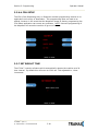
WELCOME MESSAGE
Once you have selected Welcome
Message from the Change Message
Menu, you will be prompted with the
following screen.
RECEIPT HEADER
Once you have selected Receipt Header
from the Change Message Menu, you will
be prompted with the following screen.
See the above instructions for navigating
this menu.
1700w™
(Rev 1)
© Tranax 2009 – Do Not Distribute
3.21
Section 3: Programming
Operator Manual
3.4.2 BIN LISTS
BIN numbers are card numbers that you have preset with your processor to not be
surcharged. You must set this up with your processor, who will then give you
numbers to enter in the list. These numbers will reference cards that you wish to
not be charged a surcharge for transactions. The ATM will hold up to 96 numbers (095).
If you need more BIN numbers, there is a file that can be created to load several
thousand more numbers. See Appendix for instructions.
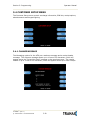
Step 1
To enter the BIN numbers select BIN List
from the Customer Setup menu. The list
can hold 2 banks of 30 numbers for a total
of 60. Bank 0 and Bank 1. Press the
OTHER button to switch between the banks.
Step 2
To add a number, press ADD and input the
BIN number with the keypad. To remove,
press REMOVE and type in the BIN number
you wish to delete from the list.
Press OTHER to switch between Bank 0 and
Bank 1.
Step 3
If you wish to view the contents of the BIN list, use the Print All Setup report. From
the Operator Function Menu, go to Reports, then Print All Setup. Any numbers
added to the BIN list will be visible from this report. NOTE: Numbers loaded via the
extra BIN file will not display on the Print Setup or any other report.
END
1700w™
(Rev 1)
© Tranax 2009 – Do Not Distribute
3.22
Section 3: Programming
Operator Manual
3.4.3 OPTIONAL FEATURES
The 1700w™ ATM offers several optional functions to improve performance and keep
the ATM functional in the event of a paper problem (jam, out of paper etc.)
LOCATION NAME
Adding a name to this location will print the name entered onto the journal records
and print all setup. This is purely a convenience option and is not required.
SELECT RECEIPT
This feature allows the ATM to complete transactions even though it may not be able
to dispense a receipt. If the ATM experiences a paper jam, or runs out of paper, the
customer will be asked if they would like to complete the transaction even though
they will not receive a receipt. If the customer answers Yes, the transaction will
continue. Following the transaction the customer’s information (what would have
appeared on the receipt) will display on the screen. The ATM will continue to operate
without use of the printer until someone accesses the Operator Function menu. At
that time the error must be corrected before the ATM will go back into service.
To enable the option, press Select Receipt, the lower portion of the screen will
display the options status.
TRANSFER TO CREDIT
Some networks do not allow customers to transfer funds to or from their credit
cards. By enabling / disabling this option you will add or remove the option button
from the customer menus. Check with your Distributor / Processor as to whether or
not they support fund transfer to or from credit cards. NOTE: If your network does
not support such transfers and you leave the option enabled, the customer can
choose it from the menu however the network will not authorize the transaction.
CHECK BALANCE
Enabling this option will ask each customer if they would like to check their balance
before each transaction.
1700w™
(Rev 1)
© Tranax 2009 – Do Not Distribute
3.23
Section 3: Programming
Operator Manual
3.4.4 CHANGE PROCESSOR
Host Processor selection changes the communications protocol to specifically match
your particular processor. In most cases this is set at the factory when your
machine is ordered, however in the event that the machine needs to be
reprogrammed for a new processor, it may be necessary to change the processor
mode.
NOTE: You do NOT need to clear NVRAM to access the Change Processor menu
To access the Host Processor mode, enter the Customer Setup menu using the
Master Password.
Communication modes are:
Modem – dial up (uses on board modem)
TCP/IP –
Standard TCP/IP
VISA FRAME TCPIP
ACK CONTROLLED TCPIP
SSL PASS THROUGH
** See section 3.31 for TCP/IP Setup Instructions **
Use the Message Format button to select the appropriate Host Processing Mode.
Available formats are:
Standard 1 (Tranax Spec)
Standard 2 (CSP200 Emulation)
Standard 3 (Extended Message)
EPS
If Standard 3 is selected, you’ll see a Standard 3 Options button which will give
access to the Extended Messaging options.
Contact your distributor or processor for which mode is appropriate.
1700w™
(Rev 1)
© Tranax 2009 – Do Not Distribute
3.24
Section 3: Programming
Operator Manual
3.4.5 SURCHARGE MODE
The Surcharge menu displays the current rate at which customers are charged per
transaction, the person or account that the surcharge funds are sent to and whether
or not the option to surcharge is enabled or disabled. The information programmed
here must match the information given to the processor at the time the account was
created. When the ATM dials into the processor for any reason, it compares the
information the processor has on file with what is programmed in this section. If
there is a discrepancy, the ATM will automatically update its surcharge information
based on the processors records. For example: If your ATM is set with the
processor to charge $1.50 per transaction and you manually enter $2.00 into the
surcharge amount, as soon as the machine connects to the processor it will revert
back to $1.50. You must contact the processor if you wish to make changes to the
surcharge information.
To set the surcharge parameters begin by entering the Surcharge Mode menu from
the Customer Setup menu. The bottom of the screen displays the current status of
each surcharge parameter.
DISABLE/ENABLE
This button toggles the surcharge option on and off.
AMOUNT
To set the surcharge amount, press the amount button and type the dollar amount
using the main keypad. Next set the decimal point using the Enter key on the
keypad. Then type the cents using the keypad and finally press Enter to finish.
1700w™
(Rev 1)
© Tranax 2009 – Do Not Distribute
3.25
Section 3: Programming
Operator Manual
PERCENT
This allows you to set the surcharge amount as a percentage of the overall amount
the customer is withdrawing per transaction. Check with your processor to make
sure that they support this function.
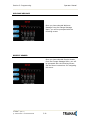
SURCHARGE OWNER
The surcharge owner can be up to 25
characters long. This owner name will
appear at the bottom of each transaction
receipt.
1700w™
(Rev 1)
© Tranax 2009 – Do Not Distribute
3.26
Section 3: Programming
Operator Manual
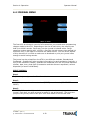
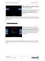
3.4.6 GRAPHICS
The Tranax 1700w™ is capable of displaying up to 8 individual graphic screens
These graphic files are created on a computer and then downloaded into the ATM
either directly at the ATM using a SDRAM card or by using the Tranax Remote
Management Software (TranRMS). When the advertisements are loaded and
enabled they will rotate in order while the ATM is waiting for a transaction and also
while the transaction is processing. There is a timer, which allows you to set a delay
before switching to the next graphic screen. Please see Appendix D at the end of
this manual for detailed instructions for creating advertisements.
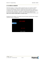
Step 1
Enter the Graphics menu and choose
“Advertise” enable or disable each
loaded graphic.
1700w™
(Rev 1)
© Tranax 2009 – Do Not Distribute
3.27
Section 3: Programming
Operator Manual
3.5 TRANSACTION SETUP
3.5.1 DISPENSE LIMIT
The dispense limit is the maximum amount of money a customer can withdraw in a
single transaction. The ATM will dispense a maximum of 40 notes per transaction.
So the dispense limit can be a maximum of 40 times the denomination of notes your
using.
For example:
If you are dispensing $10 bills the maximum dispense limit is $400
If you are dispensing $20 bills the maximum dispense limit is $800
Maximum is $900 (using either $50 or $100 bills)
To set the dispense limit, press the Dispense limit button and then enter the number
using the keys on the main keypad. Press Enter key to set the value.
1700w™
(Rev 1)
© Tranax 2009 – Do Not Distribute
3.28
Section 3: Programming
Operator Manual
3.5.2 DENOMINATION
The Denomination is the type of bill that each cassette will be dispensing. The ATM
offers a second cassette as an option. This second cassette can be programmed to
dispense notes, it can also dispense a preset number of bill sized coupons with each
transaction and finally it can dispense a “value coupon”, where you would set the
value of the coupon and the customer could purchase this using their card.
WARNING: Any change to the denomination will cause all master keys to be
deleted from the EPP keypad. If you attempt to enter the denomination setup menu,
you will be prompted and warned that continuing will cause all master keys to be
erased. The purpose of this is to prevent unauthorized changes to this critical
setting.
When programming the ATM, make sure to make any changes to the denomination
setting BEFORE you program master keys. Once keys are erased, they cannot be
recovered. New master keys will have to be loaded.
When programming the ATM, make sure to make any changes to the
denomination setting BEFORE you program master keys.
Once keys are erased, they cannot be recovered. New master keys will
have to be loaded.
To set denomination on the first cassette, press the First CST Denomination button
and then using the main keypad enter the type of bill. Options are $1, $5, $10, $50
and $100.
To set denomination on the second cassette, press the Second CST Denomination
button and then using the main keypad enter the type of bill. Options are $1, $5,
$10, $50 and $100.
1700w™
(Rev 1)
© Tranax 2009 – Do Not Distribute
3.29
Section 3: Programming
Operator Manual
3.5.3 FAST CASH
Fast Cash amounts are presented to the customer if they choose a Withdrawal
transaction. These amounts appear on screen as an easy method of selecting how
much cash they wish to withdraw for that transaction. The amounts must be
multipliers of the denomination amount.
For Example:
If your dispensing $10 bills then you can use $10, $20, $30, $40, $50 etc.
If your dispensing $20 bills then you can use $20, $40, $60, $80, $100 etc.
To set the fast cash amounts, select Fast cash from the Transaction Setup menu and
then choose from the 6 possible keys to program. Select a button and then enter
the value from the main keypad. Press Enter to confirm the setting.
1700w™
(Rev 1)
© Tranax 2009 – Do Not Distribute
3.30
Section 3: Programming
Operator Manual
3.6 TCP/IP SETUP
TCP/IP Setup is done in several menus. First you need to specify TCPIP from the
Communications Menu: [See page 3.24] Check with your processor for which
protocol they are expecting.
Once you change from Modem, to one of the TCP/IP settings, several other menus
change to support various network functions.
Operator Function Menu Æ Host Setup Æ Processor IP and Address Port
Here you will set the Host Processor IP (or URL) address and port. For some
processors an IP address (example = 121.212.1.21) is used and for others you’ll
enter a URL address (example = trans.mybank.processor).
In addition to the address, there will also be a port setting (example = 6543)
Configuration Schedule allows you to force the ATM to update configuration with the
host upon boot up. You might use this command if the terminal gets consistent Key
Errors and you want to force download of a new working key.
1700w™
(Rev 1)
© Tranax 2009 – Do Not Distribute
3.31
Section 3: Programming
Operator Manual
The ATM IP information is set using the menu found at:
Operator Function Menu Æ System Setup Æ Device Setup Æ ATM TCP Setup
This menu is only active if you have the communication mode set to TCP
[See page 3.24]
These settings will be dependant on the network connection available at the location
where the ATM is deployed. It may be necessary to contact the ISP or Network
provider for the location to determine how this should be set.
TCPIP Mode: DHCP or STATIC IP
NOTE: a Static IP address will be required if you intend to use TranRMS monitoring
software with this ATM.
Change IP Address: Enter the ATM IP address here (for static IP) or this field will
automatically populate if DHCP is used to obtain an IP automatically.
Subnet Mask and Gateway: These values will be provided by your ISP/Network
Provider and refer to the Router that you’ll be connecting to.
Ping to Gateway: This is a test which will ‘ping’ the Router and verify communication
between the ATM and the network. If this test fails, then the ATM will not reach the
host.
Ping to Host: This test attempts to verify communication with the IP address or URL
that is programmed in the ‘Processor IP Address’ menu. Note that most processors
or switches do not allow ‘pinging’ for security reasons.
1700w™
(Rev 1)
© Tranax 2009 – Do Not Distribute
3.32
Section 4: Operation
Operator Manual
SECTION 4: OPERATION
4.1 OPENING AND CLOSING
4.1.1 Opening the Security Door
Step 1
Turn the Security Cover key clockwise to
open the Security Cover. Use the Square
key included with the machine.
Step 2
To unlock the Dial or optional Electronic
Lock (see the manufacturers lock manual
included in the open me first box for default
combination) and then refer to Section
4.1.6 for lock instructions
Step 3
Turn the security Door Handle counterclockwise; then pull the security door to
open.
END
1700w™
(Rev 1)
© Tranax 2009 – Do Not Distribute
4.1
Section 4: Operation
Operator Manual
4.1.2 Closing the Security Door
Step 1
With the security door handle turned
counter-clockwise, close the security door
and turn the security door handle clockwise
until it is locked. The electronic lock
mechanism will lock itself once the T-handle
has returned to its vertical position.
Step 2
Check the T-handle to make sure the lock
has locked itself.
Step 3
With the security cover key turned
clockwise, close the security cover and urn
the security cover key counter-clockwise
until locked. Remove the key when it is
locked.
END
1700w™
(Rev 1)
© Tranax 2009 – Do Not Distribute
4.2
Section 4: Operation
Operator Manual
4.1.3 Opening the top Bezel
Step 1
The upper bezel lock on the Tranax 1700w™
is located on the back side of the top of the
machine. Insert the Bezel key and turn it
clockwise to open.
Step 2
With the Front Panel key turned, pull the
Front Panel outward.
END
1700w™
(Rev 1)
© Tranax 2009 – Do Not Distribute
4.3
Section 4: Operation
Operator Manual
4.1.4 Closing the top Bezel
Step 1
Push the Front Panel slowly until it is against
the lock mechanism. Note: you must unlock
the top bezel lock before the bezel will close
all the way.
Step 2
To lock the top bezel, turn the Bezel key
counter-clockwise until the key can be
removed.
END
1700w™
(Rev 1)
© Tranax 2009 – Do Not Distribute
4.4
Section 4: Operation
Operator Manual
4.1.5 Operating and Changing the Combination Lock (non-electronic)
Before operating the lock or changing the combination,
READ THE INSTRUCTIONS THOROUGHLY.
Changing Index
Opening Index
At the top of the dial ring, an index is provided
for normal dialing and opening. At the side of
the opening index (11 o'clock), a changing index
is provided for use only when setting a new
combination.
This is a precision lock; therefore, extreme care
must be used to align the combination number
with the index.
Turn the dial slowly and steadily. If after turning
the correct number of revolutions, any number is
turned beyond the index, the entire series of
combination numbers must be re-dialed. DO
NOT TURN BACK TO REGAIN A PROPER
ALIGNMENT WITH THE NUMBERS. Each time a
selected number is aligned with the opening index, a revolution is counted.
Please contact your distributor or consult manufacturers lock manual for
default lock combination
Step 1
Turn the dial to the LEFT, stopping when the first number is aligned with the opening
index, the FOURTH time.
Step 2
Turn the dial to the RIGHT, stopping when the second number is aligned with the
opening index, the THIRD time.
Step 3
Turn the dial to the LEFT, stopping when the third number is aligned with the
opening index, the SECOND time.
Step 4
Turn the dial slowly to the RIGHT until the bolt retracts.
END
TO LOCK
Turn dial to the LEFT at least four full revolutions.
END
CAUTION: Before closing the vault door, try the new combination several times
using the opening index.
1700w™
(Rev 1)
© Tranax 2009 – Do Not Distribute
4.5
Section 4: Operation
Operator Manual
Changing to a New Combination
To make up a new combination, select 3 sets of numbers of your own choosing.
• DO NOT USE NUMBERS BETWEEN 0 AND 20 FOR YOUR LAST NUMBER
• DO NOT USE NUMBERS ENDING IN 0 OR 5
• DO NOT USE NUMBERS IN A RISING OR FALLING SEQUENCE (e.g. 35-50-75)
Insert Figures (3)
Step 1
Using the changing index, dial the existing combination as explained in paragraphs
1-3 above.
Step 2
Hold the dial with the last number at the changing index and insert the changing key
in the keyhole in the back of the lock. Insert the key until the wing is entirely inside
the lock and comes to a positive stop.
Step 3
Turn the key one-quarter turn to the RIGHT or “clockwise”. With the changing key in
this position, turn the dial to the LEFT; stopping when the first number of the newly
selected combination aligns with the changing index the FOURTH time.
Step 4
Turn the dial to the RIGHT, stopping when the second number is aligned with the
changing index, the THIRD time.
Step 5
Turn the dial to the LEFT, stopping when the third number is aligned with the
changing index, the SECOND time. Holding the dial in this position, turn the
changing key back to the LEFT or “counter-clockwise” and remove it. The new
combination you have chosen is now set in the lock.
END
WARNING: NEVER INSERT THE CHANGING KEY IN THE LOCK WHEN THE COVER IS
REMOVED. ALWAYS BE CERTAIN THAT THE WING OF THE CHANGING KEY IS
ENTIRELY WITHIN THE LOCK BEFORE TURNING THE KEY. IF AN ERROR HAS BEEN
MADE IN SETTING A NEW COMBINATION, WE SUGGEST THAT AN ACCREDITED
LOCKSMITH BE CONTACTED.
1700w™
(Rev 1)
© Tranax 2009 – Do Not Distribute
4.6
Section 4: Operation
Operator Manual
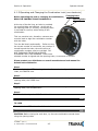
4.1.6 Operating and Changing the Electronic Lock
Before operating the lock or changing the combination,
READ THE INSTRUCTIONS THOROUGHLY*.
*See manufacturers lock manual included in the “Open Me First Box”
The LA GARD “LG Basic” series electronic lock uses a
touch key pad for all lock functions.
Power is supplied to the lock via a standard 9-volt
Alkaline battery which contained within the external
portion of the lock. The lock will warn of low voltage by
repeatedly beeping.
TO UNLOCK FROM DEFAULT COMBINATION
Step 1
Press the default combination one button at a time, (see lock manual or consult your
dealer for default combination). A beep is heard following each key press.
Step 2
If the combination is entered correctly a double-beep is heard and the internal lock
solenoid will click indicating that the lock is open and the vault handle my now turn.
Step 3
If the wrong combination is entered a triple-beep will be heard. If the correct
combination is not entered within 4 consecutive attempts a 5 minute delay or “lock
out” will begin. During this time, the led at the 2 o’clock position on the face of the
lock will flash at 10 second intervals. In addition any key press will respond with a
triple-beep. Once the 5 minutes has elapsed, 2 more consecutive failed attempts will
restart the 5 minute timer.
END
WARNING: While orienting yourself with the lock, making changes to the lock
programming (including changing the combination) ALWAYS work with the vault door
open. Do not close the vault until the lock has been thoroughly tested.
Tranax does NOT program a master combination!
1700w™
(Rev 1)
© Tranax 2009 – Do Not Distribute
4.7
Section 4: Operation
Operator Manual
Changing to a New Combination
NOTE: Combination is required to be 6 digits. Combinations of less than 6 digits will
not work.
Step 1
Begin by entering six zeros. ( 000000 )
Step 2
Enter the existing combination one time
Step 3
Enter the new combination twice. As each six digit sequence is entered, a beep is
heard.
Step 4
If the procedure is not performed correctly, at the end a triple-beep is heard and the
lock will revert back to the previous combination.
END
The LG Basic series lock includes several options including multiple user / manager
passwords. Please consult the LA Gard manual included in the “Open Me First” box
for instructions.
1700w™
(Rev 1)
© Tranax 2009 – Do Not Distribute
4.8
Section 4: Operation
Operator Manual
4.2 CASH OPERATIONS
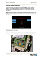
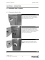
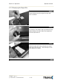
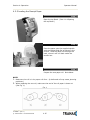
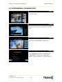
4.2.1 Adding Cash to the Cassette (TCDU)
Step 1
Open the Security Door. (Please see 4.1.1
OPENING/CLOSING THE SECUIRTY DOOR.)
Step 2
For Tranax 1700w™ with a fixed cassette
dispenser (TCDU) use the following steps.
For machines equipped with the removable
cassette dispenser (SCDU or MCDU) please
continue to Section 4.2.3.
With the security door open, remove the slide
tray screw and slide the dispenser all the way
out.
Step 3
Insert the key into the top of the reject bin
and lift up to access the cash tray.
1700w™
(Rev 1)
© Tranax 2009 – Do Not Distribute
4.9
Section 4: Operation
Operator Manual
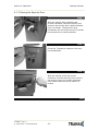
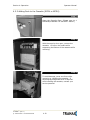
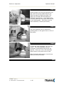
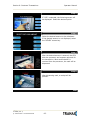
Step 4
Push the slide the push plate located inside
the cash tray back (towards the rear of the
dispenser) until it latches in place.
Step 5
Press on the latch bar to release the push
plate against the notes.
TIPS ABOUT ADDING BILLS:
1.
2.
3.
4.
Fan the notes so that the notes are not sticking together.
Remove all the notes with holes or notes that are torn.
Unfold the folded notes.
Place all the notes correctly.
1700w™
(Rev 1)
© Tranax 2009 – Do Not Distribute
4.10
Section 4: Operation
Operator Manual
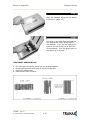
4.2.2 Emptying the Reject Bin
Step 1
Insert the key into the reject bin lock and
turn to unlock.
Step 2
Pry back on the plastic tabs at the base of the
arrow stickers on each side of the reject bin.
Lift the reject bin lid.
Step 3
With the reject bin open, remove any notes
and then close the top. Turn the key to lock
the reject bin in place.
END
1700w™
(Rev 1)
© Tranax 2009 – Do Not Distribute
4.11
Section 4: Operation
Operator Manual
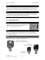
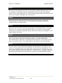
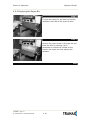
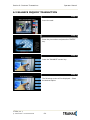
4.2.3 Adding Cash to the Cassette (SCDU or MCDU)
Step 1
Open the Security Door. (Please see 4.1.1
OPENING/CLOSING THE SECUIRTY DOOR.)
Step 2
With the security door open, remove the
cassette. Lift up on the handle while
supporting the bottom of the cassette while
removing.
Step 3
To avoid damage, never use force while
removing or installing the cassette. If
anything beyond gentle force is required
while handling the cassette, contact your
service personal.
1700w™
(Rev 1)
© Tranax 2009 – Do Not Distribute
4.12
Section 4: Operation
Operator Manual
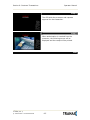
Step 4
Open the cassette using the key shown
in Section 2 (page 2.2)
Step 5
Pull back on the cash plate and load the
bills against the rollers at the back of
the cassette. If you pull the cash plate
back all the way it will lock at the front
of the cassette. Push the green lever on
the cash tray to release.
TIPS ABOUT ADDING BILLS:
5.
6.
7.
8.
Fan the notes so that the notes are not sticking together.
Remove all the notes with holes or notes that are torn.
Unfold the folded notes.
Place all the notes correctly.
1700w™
(Rev 1)
© Tranax 2009 – Do Not Distribute
4.13
Section 4: Operation
Operator Manual
4.2.4 Emptying the Reject Bin
Step 1
To open the reject bin, pull back on the tabs
located on the sides of the reject bin door.
Step 2
Remove any notes found in the reject bin and
close the door by pressing it shut.
Remember to include the number of bills
found in the reject bin when settling the
cassette.
END
1700w™
(Rev 1)
© Tranax 2009 – Do Not Distribute
4.14
Section 4: Operation
Operator Manual
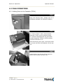
4.2.5 Loading the Receipt Paper
Step 1
Open the top Bezel. (See 4.1.4 Opening
the top Bezel.)
Step 2
Place the paper onto the supplied spindle
with the Coated Side Out as shown in the
picture. Feed the paper out through the
back, where it will curl back under the
tension bar.
Step 3
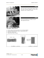
Prepare the new paper roll. Note below.
NOTE:
1. Make sure the roll is in its proper roll form. (A deformed roll may cause jamming
problems.)
2. When replacing the new roll, make sure the end of the roll paper is clean cut
(See Fig. 1).
Fig. 1
1700w™
(Rev 1)
© Tranax 2009 – Do Not Distribute
4.15
Section 4: Operation
Operator Manual
Step 4
Feed the paper over the bar behind the roll
and under the spring loaded tension bar.
Slide the paper through the guides. The
paper will not feed until the machine is
initialized (powered on). If the paper does
not feed, make sure the paper is all the way
in the loading guide. Also make sure the
roller assembly is closed (see below)
Step 5
The roller assembly can be opened by
pressing down on the green lever in front of
the printer.
Step 6
To close the roller assembly, lift up on the
rollers. The roller assembly must be
completely closed before the printer will
operate. Press up on the roller assembly
rather than on the green lever to close.
When finished loading paper, close the top
bezel and remove the key.
END
1700w™
(Rev 1)
© Tranax 2009 – Do Not Distribute
4.16
Section 4: Operation
Operator Manual
4.3 SETTLEMENT MENU
Choose Settlement from the Operator Function menu. This menu controls how many
bills have been added to the ATM as well as generating Day total and Cassette total
reports.
ADDING CASH
Step 1
Press the Add Cassette button.
Step 2
Using the main keypad, enter the number of bills added to the cassette (not the
amount of money).
Step 3
Press the enter key when finished to set the amount.
END
If you make a mistake and wish to zero out the current number of bills, you’ll need
to press Cassette total to do this. Anytime you press Add Cassette you will be
adding on to the current number of bills already programmed.
For example:
There are 50 bills in the cassette and in the settlement menu it says Current # of
Bills = 50. You wish to add 25 more bills to the same cassette, you press Add
Cassette, then type 25 from the keypad and press enter. The current number of bills
will now be 75.
Now say there are 50 bills in the cassette and in the settlement menu it says Current
# of Bills = 50. If you wish to remove 25 bills from the cassette, press Cassette
Total. This will return the number of bills in both cassettes to zero and print a
receipt showing remaining bills and loaded bills. Now press Add Cassette and enter
25 from the keypad, press enter to set. The current number of bills will now be 25.
1700w™
(Rev 1)
© Tranax 2009 – Do Not Distribute
4.17
Section 4: Operation
Operator Manual
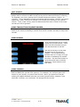
DAY TOTAL
The Day Total function keeps a running
total of the ATMs transaction activity.
When you press day total, the ATM will
print a report showing transaction totals
starting from the last time a day total
was done until now. At the same time,
the 1700w will dial into the Host
Processor and retrieve their totals for the
same time period. To the left is an
example of a Day Total Report. Once the
report is printed, the ATM will reset these
values to 0 and begin recording from this
point.
One thing to keep in mind when doing a
Day Total is that the Host (or Processor)
cuts off their transactions at a certain
time every day. If you do a Day Total
report before or after the processor has
done their cut off, you may see
discrepancies between what the terminal
had reported and what the host reports.
To avoid this, talk to your dealer and find the approximate cut off time for your
processor. Try to do your day totals at this same time. Remember that if you do not
match your processor, the missing transaction(s) will usually appear on the next
total. If you are unable to do your Day Total at the same time each day you can
program the machine to do a “Trial Day Total” automatically (see section 3.2.7).
After the Day Total has printed you will be prompted on the screen that the total has
printed and to press the Enter key to return to the menu.
1700w™
(Rev 1)
© Tranax 2009 – Do Not Distribute
4.18
Section 4: Operation
Operator Manual
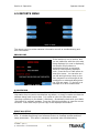
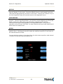
CASSETTE TOTAL
The Cassette Total function prints a
report detailing the number of bills
that have been loaded into the
cassette and how many bills were
dispensed, either to the customer,
the reject bin or used during a
dispenser test. This report will show
totals from the last time you ran a
Cassette Total to the current date.
After the Cassette Total has been
printed, all the values will reset to
zero.
NOTE: Running a Cassette Total is
the only way to clear the Settlement
value back to zero bills. After the
Cassette Total has printed you will be
prompted on the screen that the total
has printed and to press the Enter
key to return to the menu.
TRIAL CASSETTE TOTAL / TRIAL DAY TOTAL
These reports are identical to pressing Day Total or Cassette Total, the only
difference being that they will not zero out the amounts. This report is useful if you
wish to know current Total statistics without closing them out. To run these reports,
simply press the button and the report will print. Press Enter when finished to return
to the Settlement Menu.
NOTE: Trial Day Total can be set to process automatically at a preset time. See
Section 3.2.7 for information on automated scheduling of a Trial Day Total.
1700w™
(Rev 1)
© Tranax 2009 – Do Not Distribute
4.19
Section 4: Operation
Operator Manual
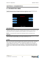
4.4 JOURNAL MENU
The Journal is an electronic record of all transactions, errors and some programming
changes made to the ATM. Depending on the size of each entry, the memory can
hold up to 40000 records. Each entry into the journal is indexed with a 5-digit
sequence number starting with <00000>. Once the journal memory has reached it’s
maximum limit, it will begin to overwrite the oldest entries. You will not be warned
of this, therefore it is critical to make sure to download or print your journal often
enough to avoid loosing records.
The journal can be printed from the ATM in two different methods, Standard and
Condensed. Standard will give complete information for each transaction (basically a
copy of the customers receipt), whereas the condensed print will only show sequence
number, date, time, what type of transaction and then amount requested / amount
dispensed (in case of withdrawal).
PRINT JOURNAL
Step 1
To print the journal, press the Print Journal button.
Step 2
You will be prompted to choose standard (PRINT) or condensed (CONDENSED
PRINT).
Step 3
The ATM will then print all journals in memory up to the last time you printed a
journal. Each time you print a journal a marker is set at that point. The next time
you print the journal, the ATM will print from that marker to the current time.
END
1700w™
(Rev 1)
© Tranax 2009 – Do Not Distribute
4.20
Section 4: Operation
Operator Manual
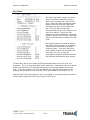
LAST X PRINT
The Last X Print option allows you to bypass the marker set when printing a journal
and go back to recover an older record (so long as the record still exists in memory).
For example, you print a journal and it includes sequence numbers <00001> to
<00100>. If you wanted to go back and reprint journal number <00080> you would
need to do a Last X Print for 20 records (100-20=80) this would give you records
100-80. To do a Last X Print, press the button and then enter a value of how many
records you wish to go back.
CLEAR TRANSACTION SEQUENCE NUMBER
This function will reset the journal sequence number back to <00000>. This may be
useful if you switch processing or switch Terminal ID numbers and want to keep new
records.
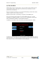
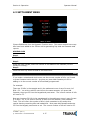
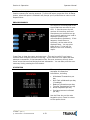
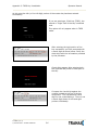
VIEW JOURNAL
View Journal allows you to visually
inspect the journal records. Press
the View Journal button and you
will see the screen to the left.
Use the Arrow keys on the main
keypad to scroll through the
records. You can also use the
buttons next to +50 and -50 to go
forward or backwards 50 records
at a time. Use the Enter button to
print the journal entry currently
displayed. Press Cancel to exit
this menu.
CLEAR JOURNAL
Clear Journal sets the current journal marker to the most recent journal recorded. It
does not delete the journal from memory. For example: You currently have 100
entries in your journal, you press Clear Journal. Now if you press Print Journal,
nothing will happen because there are no current journal entries, however if you
used Last X Journal, you could enter 100 and get all the records.
1700w™
(Rev 1)
© Tranax 2009 – Do Not Distribute
4.21
Section 4: Operation
Operator Manual
4.5 REPORTS MENU
The reports menu provides statistical information as well as troubleshooting and
error information.
ERROR CODE
If the machine is out of service, and
you are unfamiliar with the error code
being displayed (or none is displayed),
this screen will provide error
descriptions as well as corrective
action for the currently displayed
code. Press the Error Code button to
enter this screen. You can also use
you left and right arrow keys on the
main keypad to scroll through all the
possible error codes and descriptions
the ATM can report. To the left is an
example of an Error Code screen.
S/W VERSION
This screen provides the current revisions of software used in your ATM. This
information may be used to troubleshoot a problem, or simply to make sure that the
software being used is up to date. It is useful to have this information when
reporting a problem to your dealer / distributor. Occasionally check with your dealer
/ distributor for software updates. Press the S/W Version button to view the current
revisions. Press Enter key to print a copy of the displayed information.
PRINT ALL SETUP
The Print All Setup report is a complete listing of all the programming details for your
ATM. It includes everything from software versions to message screens and host
setup parameters. This report is extremely important when troubleshooting
1700w™
(Rev 1)
© Tranax 2009 – Do Not Distribute
4.22
Section 4: Operation
Operator Manual
problems. It is highly recommended to keep a copy of this on hand for when you
need to contact your service personal. To print the report, press the Print All Setup
button, when the report is finished it will prompt you to press Enter to return to the
Reports Menu.
ERROR SUMMARY
This report is a running total of all
errors that have occurred to your
ATM. It lists the errors by the
number of times they occurred.
Sometimes your machine can go
out of service and no error code is
displayed (usually with
communications problems). If this
happens, check the error
summary, as the code will be
displayed here. You can print
these errors To the left is a
sample of an error summary
report.
Press Clear to clear the report and start over. This can be useful if you have a
machine were multiple errors are occurring. If you clear the error codes and then
attempt a transaction, if that transaction fails, the error summary will only show
those errors that occurred during that last transaction. You can also print the error
summary list by pressing the Print button.
STATISTICS
This report keeps running
averages of transaction
information, including:
•
•
•
•
•
•
Withdrawal Transactions per
day
Non-Cash withdrawals per day
(if enabled)
Balance Transactions per day
Transfer Transactions per day
Notes Dispensed per day
Surcharge amount collected
per day
Use the Enter key on the main
keypad to print, Cancel to return
to the reports menu.
1700w™
(Rev 1)
© Tranax 2009 – Do Not Distribute
4.23
Section 5: Diagnostics
Operator Manual
SECTION 5: DIAGNOSTICS
5.1 DIAGNOSTICS MENU
The ATM features built-in diagnostics features to assist you in troubleshooting any
problems that may develop. Below is the main diagnostics menu.
CASH DISPENSER
This will test the ability of the cash dispenser to pull a note from one or both
cassettes (based on how the CDU is programmed) and send it to the reject bin. You
can choose from the first cassette, second cassette or both cassettes at once.
NOTE: You must have bills entered into Settlement before running this test.
PRINTER
This test will print a test receipt. If the test is successful you should receive a receipt
with three sets of sample characters for each time the test is run.
MODEM
The modem test will allow you to enter a phone number into the machine and test
dial. To run the test, press the Modem button and then press Test Dial. Using the
main keypad, enter a phone number to be dialed (for example your cell phone
number) and then press <Enter>. The modem should dial out to the number you
entered. To end the call press Modem Hangup. In most cases a failure during the
modem test will relate more to phone line problems rather than the modem circuit
itself.
1700w
(Rev 1)
© Tranax 2009 – Do Not Distribute
5.1
Section 5: Diagnostics
Operator Manual
KEYPAD
This tests the keypads of the ATM. Press the Key Matrix button and a map of all
keys will display on the screen. Press the different keys on each keypad (main and
LCD) and the appropriate key will blink on the screen. Pressing the <Cancel> key on
the main keypad will stop this test and return to the diagnostics menu.
CARD READER
This will test the three tracks of the card scanner to ensure they are reading
properly. Press the Card Scan Button, you will see a screen displaying the three ISO
tracks. Swipe your ATM card (or any card with a magnetic stripe) and the
information from that card will appear on the appropriate track. During normal
operation of the ATM only ISO Track 2 is read, however during the card swipe test all
three tracks are read at once.
AGING
The aging test is used at the factory to test machines prior to shipping and for
quality control. Selecting this test will cause the machine to perform all self tests for
an unlimited amount of time.
You can select the options in the Aging Menu for which tests to perform what interval
/ number of times you want the tests to run.
1700w
(Rev 1)
© Tranax 2009 – Do Not Distribute
5.2
Section 6: Customer Transactions
Operator Manual
SECTION 6: CUSTOMER TRANSACTIONS
6.1 OPENING PROCEDURES
This section explains how to place your ATM in service.
Step 1
Open the front panel and turn the power on. (see page 4.1)
Step 2
If there is no receipt paper, load the receipt paper. (see page 4.12)
Step 3
Open the security door and replenish the cash cassette. (see page 4.9)
Step 4
Go into the OPERATOR FUNCTION mode and input the number of bills in the cash
cassette. (See page 4.14)
Step 5
Exit the OPERATOR FUNCTION MODE.
Step 6
After connecting to the processor, the terminal will be ready for service.
Step 7
If the machine is not ready for service, please check the following:
1. Determine if the phone line is properly connected;
2. Determine if all communication parameters are correct;
3. If, after doing the above steps, the ATM is still not in service, contact your
service personnel.
END
1700w
(Rev 1)
© Tranax 2009 – Do Not Distribute
6.1
Section 6: Customer Transactions
Operator Manual
6.2 WITHDRAWAL TRANSACTION
Step 1
Insert the card.
Step 2
Enter the pin number and press the “ENTER”
key.
Step 3
Press the “WITHDRAWAL” screen key.
Step 4
If a “SURCHARGE” option is enabled, the
“SURCHARGE” screen will be displayed.
Select “YES” to continue, or “NO” to cancel.
1700w
(Rev 1)
© Tranax 2009 – Do Not Distribute
6.2
Section 6: Customer Transactions
Operator Manual
Step 5
If “YES” is selected, the following screen will
be displayed. Select the desired option.
Step 6
Select the desired amount to be withdrawn.
If the desired amount is not displayed, select
the “OTHER” screen key.
Step 7
After the desired amount is entered, the ATM
dials the processor and requests approval for
the transaction. When authorization is
received from the processor, the cash will be
dispensed.
Step 8
After dispensing cash, a receipt will be
printed.
END
1700w
(Rev 1)
© Tranax 2009 – Do Not Distribute
6.3
Section 6: Customer Transactions
Operator Manual
6.3 BALANCE INQUIRY TRANSACTION
Step 1
Insert the card.
Step 2
Enter the pin number and press the “ENTER”
key.
Step 3
Press the “BALANCE” screen key.
Step 4
The following screen will be displayed. Select
the desired option.
1700w
(Rev 1)
© Tranax 2009 – Do Not Distribute
6.4
Section 6: Customer Transactions
Operator Manual
Step 5
The ATM dials the processor and requests
approval for the transaction.
Step 6
When authorization is received from the
processor, the following screen will be
displayed and the receipt will be printed.
END
1700w
(Rev 1)
© Tranax 2009 – Do Not Distribute
6.5
Section 6: Customer Transactions
Operator Manual
6.4 TRANSFER TRANSACTION
Step 1
Insert the card.
Step 2
Enter the pin number and press the “ENTER”
key.
Step 3
Press the “TRANSFER” screen key.
Step 4
The following screen will be displayed. Select
the desired account to be transferred “FROM.”
1700w
(Rev 1)
© Tranax 2009 – Do Not Distribute
6.6
Section 6: Customer Transactions
Operator Manual
Step 5
Select the target account to be transferred
“TO.”
Step 6
Enter the desired amount to be transferred
and press the “ENTER” key.
Step 7
The ATM dials the processor and requests
approval for the transaction.
Step 8
When the authorization is received from the
processor, the following screen will be
displayed and the receipt will be printed.
END
1700w
(Rev 1)
© Tranax 2009 – Do Not Distribute
6.7
Section 6: Customer Transactions
Operator Manual
6.5 CLOSING PROCEDURE
This section explains the closing procedure for the ATM.
Step 1
Perform the “DAY TOTAL” and “CASSETTE TOTAL” functions in the “OPERATOR
FUNCTION MODE.”
Step 2
Open the security door. Remove the cash from the Cash Cassette and Cash Reject
bin.
Step 3
Print the Journal.
Step 4
If the result of the DAY TOTAL and CASSETTE TOTAL does not match the amount
counted in the Cash Cassette, refer to the Journal for verification.
Step 5
Turn the power off and close the security door.
END
1700w
(Rev 1)
© Tranax 2009 – Do Not Distribute
6.8
Section 6: Customer Transactions
Operator Manual
6.6 ERROR RECOVERY
If an error occurs the following screen will be displayed.
Step 1
To access the Operator Function menu, press
the following keys in order <Cancel>, then
<Clear>, then <Enter> then 1, then 2, then
3.
Step 2
Verify the Error that has occurred through the
“ERROR CODE” of the “REPORT MENU” in the
“OPERATOR FUNCTION,” menu and perform
the corrective action, then press the “DEVICE
INITIALIZE” screen key.
If the Error is not corrected after resetting,
contact your service personnel.
END
1700w
(Rev 1)
© Tranax 2009 – Do Not Distribute
6.9
Appendix A: Error Codes
Operator Manual
APPENDIX A: ERROR CODES
ERROR
CODES
20001
ERROR DESCRIPTION
CORRECTIVE ACTION
Unable to load a cassette.
Remove and replace cassette – Check the micro-switch
located on the inside left wall of the dispenser.
Replenish the cash – If using less than 75 bills, disable the
“Low Cash Warning” in the Transaction Setup Menu.
Empty the Reject Bin – If the bin is empty, do a Day Total
and then a Cassette Total – If that doesn’t help, check AP,
BIOS and CDU ROM versions.
Check vault door switch (located upper left corner) –
check that black and white, 2-wire connector is properly
connected at rear of main board. Bend switch forward to
aid closing problems.
Remove jammed paper – Release receipt paper drawer by
pressing the tab with the green sticker located at the front
of the printer. Remove printer to locate difficult jams.
Close the feed lever on the printer.
Replenish the paper roll.
Contact manufacturer.
20002
Low Cash.
20003
Reject Bin full.
20004
Vault Door is open.
20010
Receipt paper jam.
20012
20013
20014
Receipt feed lever open.
Receipt paper empty.
Thermal printer is
overheated.
Cash Dispenser detects
bills prior to dispensing.
Card Swipe Error.
2xx15
90001
Axxx1
Axxx2
Axxx3
Axxx4
Axxx5
Receipt Printer feed lever
open – during operation.
Thermal printer is
overheated – during
operation.
Receipt paper jam.
ADNxx
Receipt paper is empty.
Receipt paper is jamming
during loading.
Receipt Printer cutter
error.
Printer connection error.
CANCE
C0011
Surcharge Cancel
Exit sensor is not cleared
C0012
Reject gate timing sensor
not cleared.
Both reject gate and exit
sensor not cleared
Undefined
Double detect sensor is
not cleared.
1st cassette inlet sensor
not cleared.
Cassette exit sensor (L+R)
not cleared.
Axxx8
C0013
C0017
C0021
C0022
C0023
1700w
Remove any jammed bills from the dispenser.
This does not mean the card reader is bad. Just records
unsuccessful attempts at swiping cards.
Close the feed lever on the printer.
If problem is consistent then print head assembly may be
defective.
Remove jammed paper – Release receipt paper drawer by
pressing the tab with the green sticker located at the front
of the printer.
Replenish the paper roll.
Remove any jammed paper and then reload.
If consistent, printer will require repair/replacement.
Check cables between Printer and Mainboard. Remove
cables (even though they may be attached) and
reconnect.
Customer has canceled the transaction at surcharge.
Check sensor, verify that the cabling plugged into the
sensor boards is secure.
Check dispenser for jammed bills and reinitialize the
machine.
Check dispenser for any notes or obstructions.
Check dispenser for jammed bills and reinitialize the
machine.
Check dispenser and cassette for jammed bills.
Check dispenser for jammed bills and reinitialize the
machine.
(Rev 1)
© Tranax 2009 – Do Not Distribute
A.1
Appendix A: Error Codes
ERROR
CODES
C0028
C0030
C0031
C0032
C0033
C0036
C0037
C0039
C003A
C0041
C0042
C0043
C0044
C0045
C0046
C0047
C0049
C004A
C004D
C004E
C0050
C0051
C0052
C0053
C0054
C0055
C0056
1700w
Operator Manual
ERROR DESCRIPTION
CORRECTIVE ACTION
Count sensors not cleared
Check dispenser for jammed bills and reinitialize the
machine.
Turn dispenser over by hand, and then reinitialize. May
require repair.
Turn dispenser over by hand, and then reinitialize. May
require repair.
Check for notes where the cassette engages the
dispenser.
Main Motor encoder is not
synchronized
Forward motor encoder
not synchronized.
1st cassette inlet sensor
not cleared
Undefined
Exit sensor blocked while
initializing
Invalid response (or no
response) from double
detect sensor
Solenoid not responding
Too many notes requested
during a test dispense
Failed (5 times) to
dispense a note after a
successful dispense
Undefined
10 Notes rejected in a row
(single transaction)
5 notes consecutively
rejected
Note count sensor
reporting mismatch
Undefined
1st cassette failed to
dispense a note
Dispense request of “0”
notes
First cassette exit sensor
(#6, #7) not clear
1st cassette not inserted
2nd cassette not inserted
AP does not receive
response after dispense
request
Exceeded maximum
number of notes dispensed
(150) in a single trans.
1st cassette inlet sensor
not cleared
Abnormal amount of
double-detect failures
during dispense
Undefined
Long note detected at exit
sensor during dispense
Short note detected at exit
sensor during dispense
Clear any notes which may be blocking the exit sensor.
Verify the connection to the double detect module.
Verify the function of the gate solenoid.
Test dispense failed, re-run the test and check notes.
Check why notes are rejecting following at least one
successful dispense (in the same transaction).
Check the notes in the cassette. Check reject analysis for
source of rejected notes (long note, double-detect, etc)
Check reject analysis for cause of rejected notes.
Verify count of notes in the cassette against the
settlement.
Most common reason is cassette is empty. Verify that
there are notes in cassette 1. Check the quality of the
notes and condition of the pick rollers.
Check setup of CDU in Operator Menu, dispenser may
need reprogramming.
Clear the note path of any notes or obstructions.
Check cassette and verify that it’s inserted properly.
Check cassette and verify that it’s inserted properly.
AP did not validate dispense command. This is an AP
software fault, not CDU.
Check reject analysis, and verify test dispense.
Check for notes where the cassette engages the
dispenser.
Check condition of double-detect module. Check quality of
notes and pick rollers.
Clear any jammed notes or obstructions from the exit
sensor.
Clear any jammed notes or obstructions from the exit
sensor; mismatch of rejected notes.
(Rev 1)
© Tranax 2009 – Do Not Distribute
A.2
Appendix A: Error Codes
ERROR
CODES
C005A
C005B
ERROR DESCRIPTION
D0001
Undefined
2nd cassette fails to pick up
notes
3rd cassette inlet sensor
not cleared
3rd cassette inlet sensor
not cleared
Note jam at 2nd cassette
exit
4th cassette inlet sensor
not cleared
4th cassette inlet sensor
not cleared
Note jam at 4th cassette
exit
4th cassette fails to pick up
notes
4th cassette not inserted
2nd cassette inlet sensor
not cleared
Double detect sensor not
cleared while dispensing
Note leaving cassette exit
sensor did not reach DD
Reject gate timing sensor
#2 not cleared during
dispense.
Reject gate timing sensor
#3 not cleared during
dispense.
Note leaving DD sensor did
not reach gate sensor
Note leaving gate sensor
did not reach count sensor
Sensor check error
Sensor check error
Sensor check error
Sensor check error
Sensor check error
Sensor check error
Sensor check error
Sensor check error
Note jam at 3rd cassette
exit
3rd cassette not inserted
3rd cassette fails to pick up
notes
Modem initializing failure.
D0002
Reversal transaction failed.
D0012
D0013
D0014
D0020
Invalid transaction.
Invalid Amount.
Invalid Card Number.
Surcharge screen should
have been displayed.
C0060
C0062
C006A
C0070
C0072
C007A
C007C
C007D
C0080
C0081
C0082
C0083
C0084
C0085
C0086
C0090
C0091
C0092
C0093
C0094
C0095
C0096
C0097
C009A
C009D
C009F
1700w
Operator Manual
CORRECTIVE ACTION
Same as C0047, the second cassette is likely empty.
Check for notes where the 3rd cassette engages the
dispenser.
Check for notes where the 3rd cassette engages the
dispenser.
Check rollers and sensors where notes would leave the 2nd
cassette.
Check for notes where the 4th cassette engages the
dispenser.
Check for notes where the 4th cassette engages the
dispenser.
Check rollers and sensors where notes would leave the 4th
cassette.
Same as C0047/C005B, verify that there are notes in the
4th cassette.
Check cassette and verify that it’s inserted properly.
Check for notes where the 2nd cassette engages the
dispenser.
Check double-detect senor for note or obstruction.
A note seen at cassette exit sensors did not reach the
double detect module. Check for jammed notes.
Clear the note path before the reject gate.
Clear the note path before the reject gate.
Check the note path for jammed or diverted notes. Check
sensors from #5 to #2/#3.
Check for jammed notes between #2/#3 sensors and
#0/#1 sensors.
Left measuring sensor A (#6/#7)
Right measuring sensor B (#6/#7)
Left gate timing sensor A (#2/#3)
Right gate timing sensor B (#2/#3)
Exit sensor (#4)
Double Detect (#5)
Left count sensor A (#0/#1)
Right count sensor B (#0/#1)
Check rollers and sensors where notes would leave the 3rd
cassette.
Check cassette and verify that it’s inserted properly.
Similar to C0047, C005B verify that there are notes in the
cassette.
This error is reported from the host. Check that
programming is correct for this processor.
Check transaction with the processor. Verify CDU
functionality with diagnostics. Verify phone connection.
Network denial code.
Network denial code.
Network denial code.
Network denial code.
(Rev 1)
© Tranax 2009 – Do Not Distribute
A.3
Appendix A: Error Codes
ERROR
CODES
D0024
D0039
D0051
D0052
D0053
D0054
D0055
D0057
D0058
D0061
D0075
D0078
D0080
D0083
D0086
D0091
D0092
D0093
D0094
D0095
D0096
D0097
D0098
D0099
D009A
D009B
D009C
D009D
D009E
D009F
D00A0
D00A1
D00A2
D00A3
D00A4
1700w
Operator Manual
ERROR DESCRIPTION
CORRECTIVE ACTION
Exceeds issuer withdrawal
limit.
No credit account.
Insufficient funds.
No checking account.
No savings account.
Expired Card.
Invalid PIN.
Transaction not permitted
– card
Transaction not permitted
– Terminal
Exceed withdrawal limit.
Number of PIN tries
exceeded.
No Account.
Invalid Date.
Cannot verify PIN.
Cannot verify PIN.
Bank unavailable.
System unavailable.
Transaction serial number
mismatch.
Record format mismatch.
Routing ID mismatch.
Terminal ID mismatch.
Response type mismatch
(reversal).
Response type mismatch
(day-close).
Response type mismatch
(Configuration).
Response type mismatch
(Withdrawal, Balance,
Transfer).
STX omitted.
ETX omitted.
FS omitted (after response
code).
FS omitted (after retrieval
reference number).
FS omitted (after system
trace audit number).
FS omitted (after account
balance).
FS omitted (after available
balance).
FS omitted (after available
balance).
FS omitted (after
authorization response
text).
ETX is in wrong place.
Network denial code.
Network
Network
Network
Network
Network
Network
Network
denial
denial
denial
denial
denial
denial
denial
Network denial code.
Network denial code.
Network denial code.
Network denial code.
Network denial code.
Network denial code.
Network denial code.
Network denial code.
Network denial code.
Contact host processor.
Contact host processor.
Verify Routing ID number – Contact host processor.
Verify Terminal ID number – Contact host processor.
Contact host processor.
Contact host processor.
Contact host processor.
Contact host processor.
Contact host processor.
Contact host processor.
Verify that version of Mini-Bank Software
processor. Contact host processor.
Verify that version of Mini-Bank Software
processor. Contact host processor.
Verify that version of Mini-Bank Software
processor. Contact host processor.
Verify that version of Mini-Bank Software
processor. Contact host processor.
Verify that version of Mini-Bank Software
processor. Contact host processor.
Verify that version of Mini-Bank Software
processor. Contact host processor.
Verify that version of Mini-Bank Software
processor. Contact host processor.
matches host
matches host
matches host
matches host
matches host
matches host
matches host
Verify that version of Mini-Bank Software matches host
processor. Contact host processor.
(Rev 1)
© Tranax 2009 – Do Not Distribute
code.
code.
code.
code.
code.
code.
code.
A.4
Appendix A: Error Codes
ERROR
CODES
D00A5
Operator Manual
ERROR DESCRIPTION
CORRECTIVE ACTION
Verify that version of Mini-Bank Software matches host
processor. Contact host processor.
D1800
FS omitted (after total
cash dispense amount in
day close).
FS omitted (after total non
cash dispense amount in
day close).
FS omitted (after
surcharge amount in day
close message).
FS omitted (after
surcharge in configuration
message).
ETX omitted (from
configuration message).
Modem is not responding.
No Connection.
ENQ not received from
host.
Transmission error.
NAK sent 3 times to host.
Modem connection time
out – host not responding.
Modem cannot support
connection – excessive line
noise (usually D1704/06)
No dial tone.
D1900
D2000
No answer.
Phone line busy.
D2100
D2200
Modem initializing error.
EOT not received from
host.
E000x
RMS port failure, response
time out, modem failure,
no dial tone.
Current Number of bill is
0.
No Surcharge Owner set.
No Surcharge Amount.
No refresh time set when
advertisement is enabled.
No Advertisement text
when advertisement is
enabled.
Dispense limit set error
(less than 25 notes)
Denomination Set error.
D00A6
D00A7
D00A8
D00A9
D0300
D1000
D1100
D1200
D1300
D1500
D170x
F0001
F0002
F0003
F0004
F0005
F0006
F0007
F0008
F0009
1700w
Fast Cash Set error
(exceeded dispense limit).
Master Key index is
invalid.
Verify that version of Mini-Bank Software matches host
processor. Contact host processor.
Verify that version of Mini-Bank Software matches host
processor. Contact host processor.
Verify that version of Mini-Bank Software matches host
processor. Contact host processor.
Contact host processor.
Verify modem function.
Verify modem function.
Contact host processor.
Verify modem function.
Verify host phone number – See D170x.
Verify host phone number – verify modem speed – See
D170x. If consistent, it could be a defective modem.
Phone line connected to ATM will not support Datacommunication. In line filter may fix this. Excessive EMI
emissions from outside source (neon sign, freezer).
Verify that incoming phone line is plugged into “line”
rather than “Phone” on mainbaord. Phone line is in use or
is being shared with another phone device (FAX, POS,
phone)
Verify host phone number – See D170x
Verify host phone number – call line with handset and
check for busy signal – See D170x
Check modem.
Contact host processor.
Verify RMS settings (Host Setup) – See D170x
Load notes into the cash cassette – use Add Cassette
function in Settlement.
Set Surcharge owner – (Customer Setup)
Set Surcharge amount – (Customer Setup)
Set refresh timer – (Customer Setup)
Set Advertisement text – (Customer Setup)
Set Dispense limit – (Transaction Setup)
Valid Denomination are $10, $20, $50, $100 –
(Transaction Setup)
Check the Fast Cash amount. (Transaction Setup)
Check Master Key index – verify checksum (Host Setup)
(Rev 1)
© Tranax 2009 – Do Not Distribute
A.5
Appendix A: Error Codes
ERROR
CODES
F000A
F000B
F000C
F000D
F000E
F000F
F0010
F0011
F0013/
14
F0015
F0016
1700w
Operator Manual
ERROR DESCRIPTION
CORRECTIVE ACTION
Master Key is empty.
Host Telephone Number is
not set.
Error Retry timer is not
set.
RMS Password is not set
when RMS is enabled.
RMS phone number is not
set when RMS send is
enabled.
Terminal ID is not set.
Routing ID is not set.
Master Key Serial number
is not set
NVRAM Failure
Check Master Key checksum – reinject key (Host Setup)
Set Host Telephone Number – (Host Setup)
Serial Number not Set
Master Password left at
default
Set Error retry time (Host Setup)
Set RMS Password – (Host Setup)
Set RMS Phone number – (Host Setup)
Set Terminal ID number – (Host Setup)
Set Routing ID number – (Host Setup)
Set Master Key serial number – (Host Setup)
Fatal error, defective memory chip. Replace Mainboard.
Set Serial number in Operator Menu
ATM will not go into service with the default master
password. The master password must be changed from
default.
(Rev 1)
© Tranax 2009 – Do Not Distribute
A.6
Appendix B: Keypad Addendum
Operator Manual
APPENDIX B: CLEARING NVRAM
To clear NVRAM on the Tranax 1700w™, begin by entering the Operator Function
Menu using the Master Password. Next enter the Customer Setup Menu.
Press the lowest button on the right side of the LCD panel. This will give you access
to the CLEAR NVRAM Menu.
*** WARNING ***
Once in the CLEAR NVRAM Menu, there is no extra authorization before data will be
wiped out permanently. DO NOT press any key within this menu unless you are
absolutely sure you want to permanently delete this data!
CLEAR JOURNAL
Selecting this will delete all journal data permanently
CLEAR NVRAM
This will delete all programmed parameters and return everything (including
passwords) to the default settings. This does NOT include the master keys which are
stored in the EPP.
CLEAR JOURNAL AND NVRAM
This option performs both of the options listed above. Both the programmed
parameters and journal are permanently deleted and all settings are returned to
default.
USE CAUTION WITH THESE FEATURES – DATA LOST CANNOT BE RECOVERED
1700w
(rev 1)
© Tranax 2009 – Do Not Distribute
B.1
Appendix C: TDES Key Installation
Operator Manual
APPENDIX C: TDES Key Installation
TDES Master Key Installation
Triple - Data Encryption Standard or TDES was designed as a way to strengthen the
security of the master key by upgrading from a 16 bit key to a 32 bit key. In addition to
the required software changes to support the TDES, the specification calls for a pin-pad
to encrypt any data sent between the keypad and the CPU. In this new configuration the
master keys are stored securely within the pin-pad, rather than the mainboard as done
previously.
Hardware Specification:
Tranax 1700w™ with PCI EPP (Encrypted Pin Pad)
Installation Procedure:
To access the Key Management menu from Host Setup, you’ll need to enter the Secure
Mode Password (parts 1 and 2). See page 3.6 for Secure Mode instructions.
Default Secure Mode password is:
Part #1 = 000000 / Part #2 = 000000
Access the Key Mode selections by entering
the operator function menu
[ENTER]+[CLEAR]+[CANCEL] – 1, 2, 3 (see
operator manual).
Enter Master Password and choose Host
Setup
Note: Master Password is required to change
master key.
NOTE: You must change the Secure Mode Password from default before any changes can
be made to Key Management, or enter any keys. Change the default passwords for Part
#1 and Part #2 and then completely exit the Operator Menu. Once you go back in and
use the new Secure Mode Passwords, you’ll be able to make changes or enter keys.
1700w
(rev 1)
© Tranax 2009 – Do Not Distribute
C.1
Appendix C: TDES Key Installation
Operator Manual
1) Select Key Mode
The table below describes the format for each key mode.
DES
2 - 16 digit master keys entered as Part A and Part B.
Dual Master
Key
2 - 16 digit master keys entered as Part A and Part B (a
common key is entered, and then a working key is
downloaded from the host).
Unique Key,
DES
2 - 16 digit master keys entered as Part A and Part B with 10 digit unique serial number entered prior to each
part.
TDES
2 – 32 digit master keys entered in 16 digit pieces, Part A
(left and right) and Part B (left and right)
Unique Key,
TDES
2 – 32 digit master keys entered in 16 digit pieces, Part A
(left and right) and Part B (left and right) - 10 digit unique
serial number entered prior to each part.
MAC
2 -16 digit master keys entered as Part A and Part B, with
2 additional 16 digit numbers entered as MAC Part A and
Part B
Unique Key,
MAC
2 -16 digit master keys entered as Part A and Part B, with
2 additional 16 digit numbers entered as MAC Part A and
Part B - 10 digit unique serial number entered prior to
each part of the master key only.
TDES, MAC
2 – 32 digit master keys entered in 16 digit pieces, Part A
(left and right) and Part B (left and right), with 2
additional 16 digit numbers entered as MAC Part A and
Part B
Unique Key modes use a unique 10 digit serial number that is entered before each half of
the master key to allow the processor to bind the key to the terminal ID automatically.
In cases where the processor provides a serial number that is less than 10 digits, zeros
must be added at the beginning of the number to equal 10 digits.
1700w
(rev 1)
© Tranax 2009 – Do Not Distribute
C.2
Appendix C: TDES Key Installation
Operator Manual
2) Enter Master Key
Master Key security requires that no one person has access to all parts of the key. To
ensure this, the processor will provide keys in separate sealed envelopes (sometimes
referred to as “key components”). Each envelope contains either one or two 16 digit
keys and in the case of unique key, a serial number. The diagram below shows a
sample Unique Key, TDES master key.
Begin by choosing Edit Master Key from the
menu
Depending on Key Mode, the menu prompts
for Part A and Part B.
The Edit Master Key interface is designed so that Parts A and B can be entered at
completely different times and in either order (Part A first, or Part B first). If a technician
is dispatched to enter a key part, choose Check Key from the Key Management menu to
determine which part of the key has already been entered.
Partially entered keys will appear in the
index as #### or **** which denotes that
either part A or part B has been successfully
entered. (A = #, B = *)
This would tell the second technician that
they need to enter their key as Part B on
index 12.
Part1 = Part A / Part2 = Part B
1700w
(rev 1)
© Tranax 2009 – Do Not Distribute
C.3
Appendix C: TDES Key Installation
Operator Manual
Once you have selected Part A or B, you’ll
be prompted to enter a Key Index.
This index points to the location where the
key will be stored. There are 16 possible
memory locations (0-15) available. Unique
master keys must be stored at location #12,
and MAC keys at location #15.
The interface will default the values for Unique and MAC keys regardless of what you
enter. It is very important to remember that both parts of a key must be entered on the
same index. If you enter Part A on index #2 and Part B on index #3 the key will not be
complete. Use the Check Key function (shown above) to determine where your keys
parts have been entered.
If entering a Unique key, next you’ll be
prompted to enter the key serial number.
This 10 digit number is found on the
paperwork containing your master key(s).
If the number the processor has provided is
less than 10 digits, you’ll need to add zeros
to the beginning of the number to equal 10
digits.
In the example shown at left, the serial
number is 235913. This 6 digit number
would be changed to 0000235913 to
create 10 digits.
The next step is to enter the master key
itself. If you are using TDES, you’ll need to
enter the left portion first.
After entering the key, you’ll be prompted to
enter it a second time for verification.
1700w
(rev 1)
© Tranax 2009 – Do Not Distribute
C.4
Appendix C: TDES Key Installation
Operator Manual
The 16 digit alpha-numeric key is
entered using the pin-pad only.
Letters are entered by using the arrow
and function keys. Use the pin-pad
layout below.
1
2
3
F
4
5
6
E
7
8
9
D
A
0
B
C
EPP (Encrypted Pin Pad) Master Key Alpha-Numeric Key Layout
1700w
(rev 1)
© Tranax 2009 – Do Not Distribute
C.5
Appendix C: TDES Key Installation
Operator Manual
At this point the left (or first 16 digit) portion of the master key has been entered
successfully.
If you are entering a 32 bit key (TDES), the
second or “Right” half of the key is entered
next.
This option will only appear when in TDES
mode.
After entering the right portion of the
key successfully you’ll be prompted with
a check digit as shown below. Verify the
check digit with the information provided
by the processor.
Check digits appear after entering both
the right and left portion of each part of
the key.
Compare the check digit against the
number located at the top of the key
component. This represents a check
digit for the combined keys. There is not
a check digit shown for left and right
portions individually.
1700w
(rev 1)
© Tranax 2009 – Do Not Distribute
C.6
Appendix C: TDES Key Installation
Operator Manual
After successfully entering both the left and
right portions of Part A, you’ll be returned to
the Edit Master Key menu.
At this point you can proceed with Part B, or
if Part B is to be entered at a later time you
can exit the menu and power off the
machine until both halves of the key are
entered.
Part B is entered with the same procedure given for Part A. Enter the left and right (for
TDES) portions of the keys and verify the check digits against what has been provided by
the processor.
3) Verifying Master Key
Once both Part A and Part B have been
entered successfully, the key management
menu will display a check digit for the key
index where the master key was entered. If
no check digit is entered, use the check key
screen to determine where the key parts
were entered, then re-enter the keys as
necessary.
At this point, the master key is successfully entered. If all other parameters have been
entered properly, power off the ATM and power on to connect to host and initialize the
keys.
1700w
(rev 1)
© Tranax 2009 – Do Not Distribute
C.7
Appendix D: Graphics Installation
Operator Manual
APPENDIX D: Graphics Installation
Advertisement screens can be loaded to the Tranax 1700w™ machine either
using a SDRAM card (at the ATM) or by using TranRMS monitoring software
(to load remotely). Please see below for basic file format specifications and
instructions for use with a SDRAM card.
WELCOME
Center Advertisement Graphic
Width : 528 Pixels
Height : 386 Pixels
File Name
center1.bmp
center2.bmp
…..
center8.bmp
File Size : 204,888 BYTES
Bmp File Format
: 8bit (256 colors) BMP
: No Compression
You can have up to 8 center graphic files and must be named as followed:
center1.bmp, center2.bmp, and so on up to center8.bmp
* DO NOT use more than 256 colors when creating the graphic images. The
1700w™ was designed to use graphics of that format for efficiency and
best performance*
1700w
(rev 1)
© Tranax 2009 – Do Not Distribute
D.1
Appendix D: Graphics Installation
Operator Manual
Loading Graphics using SD (Secure Digital) card
SD card should be less than 2GB capacity and formatted as FAT
or FAT16 file system
SD card reader is required to load files from your PC
To prepare the SD card for uploading graphics.
1. Remove all the data from the SD card.
2. Create a blank file called update.acu and save it on the card.
To create this file:
a. Open up a blank notepad document.
[Start Æ All Programs Æ Accessories Æ Notepad]
b. Save the blank document as “update.txt” in the SD card.
c. Once it’s saved rename the file to “update.acu”.
once renamed, the icon changes
After the “update.acu” file has been created, copy it to the root folder of
the SD card.
1700w
(rev 1)
© Tranax 2009 – Do Not Distribute
D.2
Appendix D: Graphics Installation
Operator Manual
3. Open the SD card in ‘My Computer’, and create a folder called
“Common”.
4. Open the “Common” folder, and create a sub-folder called “img4SCR”.
5. Inside the img4SCR folder is where you want to copy all your graphic
files.
- The graphic files must follow the naming convention that we describe
on page 1. (ie: center1.bmp, center2.bmp or top1.bmp, top2.bmp).
6. Once your graphic files are copied, insert the SD card into the SD card
slot on the mainboard located behind the LCD.
7. Power off, then power on the 1700w™ with the power supply switch.
8. When the ATM is fully initialized then remove the SD card.
Enabling the Center Graphics:
1. Go into the Operator Menu.
2. Then to Customer Setup > Graphics > Advertise EN/Disable and go
through each advertisement you want to show up and turn it ON.
Enabling the Banners Graphics:
1. Go into the Operator Menu.
2. Then to Customer Setup > Graphics > Banner EN/Disable and go
through each banner you want to show up and turn it ON.
Windows XP users:
Before creating the file in step #2, you may need to change your file options.
Open a folder and click on “Tools”, select Folder Options
Make sure Folder Options match
those shown here. Specifically
the “Hide extensions for known
file types” option which needs
to be unchecked.
If these options are not set
properly, the update.acu file
may not function, causing the
graphics to not load.
1700w
(rev 1)
© Tranax 2009 – Do Not Distribute
D.3
Appendix E: Preventative Maintenance CDU
Operator Manual
APPENDIX E: CDU Maintenance
Dispenser Sensor Cleaning Instructions
The Tranax MCDU (and TCDU) dispensers contain several optical sensors
used to count and measure notes as well as time note delivery.
Through normal use, dust can collect on the sending side of the sensor pairs,
causing the readings to skew which can cause C00xx errors.
Depending on environmental conditions at the machine location, Tranax
recommends periodic cleaning of these sensors to prevent errors or to
correct error conditions. Specifically C0083/84/85, C0012 and C002x errors
have been shown to be caused by contaminated sensors. Particularly the
sensors located at the exit gate.
Each sensor pairs contain a sending sensor, and a
receiver. The sending sensor looks like a clear LED
mounted to a circuit board. As shown at right.
To clean the sensor, simply wipe the surface using a
cotton-swab (Q-Tip®) or any clean soft cloth.
It is not necessary or recommended to use a solvent.
Dust contamination is not always visible.
1700w
(rev 1)
© Tranax 2009 – Do Not Distribute
D.1
Appendix E: Preventative Maintenance CDU
Operator Manual
MCDU Sensor Locations
Front / Top
There are 3 sensors located behind
the metal bracket, directly above the
Reject Bin. These can be reached by
inserting a cotton swab through the
front bracket.
1700w
There are 2 sensors located in the rear
inside portion of the dispenser. Open
the lid of the dispenser and reach
between the belts. Be careful to not
bump the top sensor boards.
(rev 1)
© Tranax 2009 – Do Not Distribute
D.2
Appendix E: Preventative Maintenance CDU
Operator Manual
MCDU Sensor Locations
Rear
There is a sensor located on the lower rear
portion of the dispenser.
1700w
(rev 1)
© Tranax 2009 – Do Not Distribute
D.3
Appendix E: Preventative Maintenance CDU
Operator Manual
TCDU Sensor Locations
Front
The TCDU or 800 note fixed cassette has sensors located in the front of the
dispenser (visable when you open the vault door)
These lower sensors are hard to see in this picture, they are just behind the
metal plate containing the double-detect module.
1700w
(rev 1)
© Tranax 2009 – Do Not Distribute
D.4