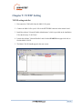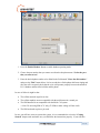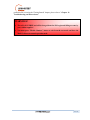
1
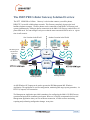
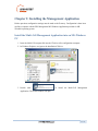
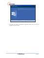
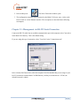
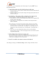
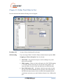
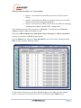
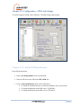
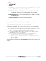
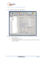
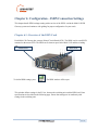
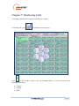
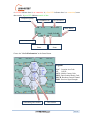
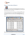
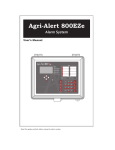
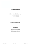
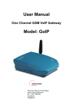
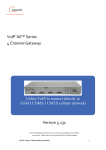
DTT PRI GSM(CDMA) Ingate PRI Gateway ISDN PRI to Cellular Gateway Version 3.361 User Manual Connecting Office Phones to Cell Phones While Greatly Reducing Costs DTT PRI GSM Ingate 1 / 54 For additional assistance please contact us: Support Team Discovery Telecom Technologies Skype: discoverytelecom Tel: +1801 7900348 Email: Web: [email protected] www.dtt.tw Usage Warnings 1) High voltage transients, surges, and other power irregularities can cause extensive damage. It is the user's responsibility to provide a power protection system. 2) It is the user's responsibility to install, operate, and maintain the system in ac cordance with all applicable codes, regulations, and safety measures. Trademark and Patents All trademarks, patents and copyrights apply. General Manual Notes Without a notice and without obligation, the contents of this manual may be revised to inco rporate changes and improvements. Every effort has been made to ensure that the information is complete and accurate at the time of publication. Nevertheless, Discovery Telecom cannot be held responsible for errors or commissions. The screen snapshots in this manual may have older version labels than your delivered package version. 2 / 54 Dear Customer, We thank you for purchasing our Cellular Multi Cell to ISDN PRI Gateway. This Gateway is in the GSM technology and will be referred as a cellular Gateway. The information in this manual does not constitute a warranty of performance, although the information has been compiled and checked for accuracy by Discovery Telecom Ltd. All our products are developed and produced by experienced engineers, who aspire to achieve customer satisfaction, utility value and reliability of products. Warranty Policy The PRI Multi Cell ISDN Cellular Gateway product you have purchased is under warranty for 1 year from the date of purchase, by the original purchaser. In case of defects of materials or workmanship, Discovery Telecom will replace it free of charge. This warranty applies to hardware/software but does not include SIM Cards. This warranty will not be honored if the device has been mishandled in any way. We hope you enjoy our product and we will be happy to receive any comments you may have. This will enable us to improve our products and the t echnical support that we give to every customer. 3 / 54 Table of Contents User Manual ...................................................................................................................................1 Getting Started ................................................................................................................................ 5 Check Your Package Items ...........................................................................................................10 The ISDN PRI Cellular Gateway Solution Overview ....................................................................11 Chapter 1: Connecting the Cables ..................................................................................................13 Chapter 2: Installing the Management Application ........................................................................15 Install the Multi-Cell Management Application into an MS -Windows PC .................................15 Chapter 3: Basic Configurations with the Management Application .............................................. 18 Chapter 3.1: Management via RS -232 Serial Connection........................................................... 19 Chapter 3.2: Management via Ethernet interface Connection ..................................................... 20 Chapter 3.3: Setting Date, Time and Password ..........................................................................21 Chapter 4: Configuration - Defining Groups of Ports .....................................................................23 Chapter 5: Configuration - Port and SIM ....................................................................................... 25 Chapter 5.1: Define Dial Settings for Each Port .........................................................................25 Chapter 5.2: Define Work Mode for Port ................................................................................... 27 Chapter 5.3: Configuration - SIM Card Settings ........................................................................29 Chapter 5.3.1: Define SIM Specifications .............................................................................. 29 Chapter 5.3.2: Define Type of Channel and Operator Lock .................................................... 30 Chapter 5.3.3: Set Time Table for SIM .................................................................................. 31 Chapter 6: Configuration - ISDN Connection Settings ...................................................................32 Chapter 6.1: Overview of the ISDN C ard .................................................................................. 32 Chapter 6.2: Configuration - B-Channels, Ports and Prefixes ..................................................... 35 Chapter 6.2.1: Assigning Ports and Defining Prefixes ............................................................ 35 Chapter 6.2.2: Assigning B -Channels to Dial Numbers .......................................................... 39 Chapter 6.2.3: Access to GSM & Access to E1 ......................................................................41 Chapter 7: Monitoring Calls ..........................................................................................................43 Chapter 8: Generating Call Reports ............................................................................................... 46 Chapter 9: TCP/IP Setting ............................................................................................................. 48 Chapter 10: Operational Test .........................................................................................................50 Chapter 11: Troubleshooting and Known Issues ............................................................................ 53 Chapter 11.1: The Handset ........................................................................................................53 Chapter 11.2: The Management Application Debug Window .................................................... 54 Chapter 12: FAQ ........................................................................................................................... 55 4 / 54 Getting Started Discovery Telecom Tech team is glad you have cho sen to use the Discovery's Multi Cell PRI Gateway for your needs. We will do our best to make your installation efforts as well as day -to-day configuration and monitoring tasks to be as pleasant tasks as possible. We wish you a smooth operation while greatly saving your office mobile phone calls. This chapter is your map for installation, configuration , and monitoring tasks and includes a short explanation on each stage as well as references for more elaborated explanations, drawings and examples in other chapters. The following is a list of tasks you should perform; you can go over them sequentially or skip whenever they're optional and not required for your c urrent needs. It is advised that you will use the following tasks as your Do-To-List. Mandatory - Check that all package items are included Refer to "Check your Package Items" chapter for checking that all items specified are in your package. Mandatory - Install the Management Application Install the MS-Windows Management Application with the provided CD, on the PC/Laptop allocated for the system management . Refer to "Chapter 2: Installing the Manager Application" for further explanations. Mandatory - Connections o Install Power Cable o Install Ground Cable o Install Antennas o Install ISDN cable o Install RS-232 (Comport cable) serial or RJ -45 Ethernet cable Refer to "Chapter 1: Connecting the Cables" for specific and detailed guidelines. 5 / 54 Mandatory - General configurations In order to operate the system , a mandatory basic setup should be performed in one of the two optional connections, seria l RS-232 or via Ethernet interface. The 1st time configuration is recommended to be performed via RS -232 while monitoring and reports in a later stage are recommended to be performed via IP. Refer to "Chapter 3: Basic Configurations with the M anagement Application". Mandatory – 1st time system configuration via RS -232 Use the RS-232 connection and PRI Management MS -Windows Application for your first time configuration. You can use this method for later day -to-day management, however the option to manage your PRI cellular Gateway system via IP is highly recommended as you can have the management done remotely from the system via internet connection. Refer to "Chapter 3: Basic Configurations with the Management A pplication" and "Chapter 3.1: Management via RS -232 Serial connection". Optional: Optional - Setting the TCP/IP connections If you wish to operate the Management Application for system management via internet connection, the proper TCP/IP settings should be performed. Refer to "Chapter 9: TCP/IP Setting". Optional - Managing the system via Ethernet interface connection In order to manage, configure and mo nitor the system via Ethernet, the system TCP/IP connection, the Ethernet cables , and the PRI Management MS -Windows Application should be properly installed and configured. Refer to "Chapter 3.2: Management via Ethernet interface Connection". 6 / 54 Optional Task - Configurations In order to operate the system and start making calls, a certain setup should be performed. Refer to the following chapter s that match your configuration need s: Chapter 3.2: Management via Ethernet interface Connection Chapter 4: Configuration - Defining Groups of Ports Chapter 5: Configuration - Port and SIM Chapter 5.1: Configuration – Define Dial Settings for Each Port Chapter 5.2: Define Work Mode for Port Chapter 5.3: Configuration – SIM Card Settings Chapter 6: Configuration - ISDN Connection Settings Chapter 6.2: Configuration – B-Channels, Ports and Prefixes Optional Task - Monitoring calls The PRI Management MS-Windows Application enables you to monitor calls in real time. It is recommended that the Management Application PC will be connected via IP, in order to enable flexible and continues connection with the monitored system. Refer to "Chapter 7: Monitoring Calls" for further explanations. Optional Task - Making usage reports The PRI Management MS-Windows Application enables you to generate call reports and export the report files for additional analysis. It is recommended that the Management Application PC will be connected via IP, in order to enable flexible and continues connection with the monitored system. Refer to "Chapter 8: Generating Call Reports". Optional - Test call between office phone and c ellular phone Make a test call from your office phone to a cellular c ell phone. This will enable you to trace problems in your settings and will guide you in finding the root cause of your operational error if any, and to overcome operational problems. If still , after all the guidelines and sub tests completed , you could not trace the problem, you are referred to "Chapter 10: Operational Test". In this chapter we'll make handset test call, which is mainly used to check the operation and c ompatibility of the Multi-Cell system with the local cellular network. 7 / 54 If you had problems in setting up the system, or you completed the setups according to this manual and you still have operational problems, refer to the proper chapter of known issues and troubleshooting. Refer to "Chapter 11: Troubleshooting and Known I ssues". 8 / 54 For getting the most updated product info on the w eb Refer to www.dtt.tw At menu: PRI/BRI Gateways At sub menu: PRI ISDN Gateway (note: CDMA capabilities not supported in your package) Please give us feedback to improve your PRI Multi-Cell Gateway product Please let us know your feedback and enhancement ideas to improve the product to your best value. Email: [email protected] 9 / 54 Check Your Package Items Please verify that your package contains the following components before installation: Main hardware device - The Multi-Cell PRI Gateway 110/220V power supply cable Software Installation CD - Installation kit of the PRI Management MS -Windows Application, this user manual file and additional auxiliary utilities. 8 cellular antennas - Large sized RJ-11 phone handset - For testing voice calls from different ports RJ-45 - RS-232 serial connection cable - we'll be referred as Comport cable in this manual 4 additional cables o RJ-45 ISDN E1 cross connect cable For direct ISDN E1 connection without intermediate PBX o RJ-45 ISDN E1 regular connection cable For ISDN E1 connection to a PBX o RJ-45 Ethernet cross connect cable For direct IP connection to a PC first time o RJ-45 Ethernet regular connection cable For connection to the Multi -Cell through IP Note: The ground cable is not supplied as it is very common, low cost and various types apply. 10 / 54 The ISDN PRI Cellular Gateway Solution Overview The DTT ISDN PRI to Cellular Gateway is a device that connects your office phones DIRECTLY to mobile cellular phone networks. This Gateway completely bypasses the local landline telephone company. 30 office phones can be connected to each Multi-Cell Gateway and operate simultaneously. Each port (phone connection) in the Multi-Cell Gateway can hold four c ell phone SIM cards. You can configure each port so that the most economical SIM is active at a given time in call scenario. One Location in the World PRI Management MS-Windows Application GSM Base Another Location in the World Mobile Cellphones Mobile Cellphones GSM Base IP Network IP / RS-232 PSTN PRI Desktop Phones PRI Desktop Phones An MS-Windows PC/Laptop can be used to operate the PRI Management MS -Windows Application. The application is used for configuration, monitoring and usage reports generation, via RS-232 (Comport) or IP connection. The Management Application provided is mandatory for configuring the Multi-Cell PRI Gateway operation and optional for monitoring and reports. However it is highly recommended to leave the Management Application always on via an Internet connection , in order to allow monitoring, reporting and performing configuration changes at any time. 11 / 54 The PRI Management MS-Windows Application provides the following functio ns: Configuration - Connections, ports, channels, SIM car ds and operational modes can be configured. Monitoring - Call operations can be monitored from the Management Application. Therefore you may wish to leave a computer permanently connected to the Multi -Cell PRI system at all times. Reports and statistics - Call reports, calls history, antenna reception, status logs and more, can be generated for analysis in standard MS -Windows data processing tools such as MSACCESS and MS-EXCEL. 12 / 54 Chapter 1: Connecting the Cables You have several cables to connect to th e Multi-Cell PRI Gateway. Some are mandatory and some are optional, based on the specific usage. In the following chapters we will use the term "switching equipment", which is any ISDN PRI equipment connected to the ISDN connector in the Multi -Cell Gateway. Basic Connections Power cable 110/220V - The power cable is supplied and should cover all main voltage electricity services in the world. However , you should check that the cable plug is suitable with your country's outlet socket. Connect a 120 V (North America), or 240 V (Europe) power supply cable to the Multi-Cell Gateway. Ground cable - The ground cable is not supplied and can be any ground cable that is available in electricity shop and best suite d for your ground socket available. Connect the ground wire to a suitable ground socket or connection available. ISDN cable - The regular ISDN cable is used to connect the system to the PBX, serving the office landline phones. For the regular ISDN cable, connect the ISDN line from the telephone switching unit in your office to the Multi -Cell unit. Connect the ISDN line to the socket labeled "ISDN" in the Multi-Cell unit, as shown below. Comport cable - This cable is used between the Management Application PC via RS-232 serial COM port and RJ-45 connected the "COM" socket in the Multi-Cell PRI Gateway unit. This connection is recommended for first time setting. RJ-45 Ethernet cable - The regular RJ-45 Ethernet cable is used for connection between PC with the Multi-Cell PRI Gateway Management Application and the Multi-Cell PRI gateway system via IP. This is an additional option which can be used to connect the Management Application PC to the system and it has the benefit of enabling operating management of configuration, monitoring and reporting from a ny location where the MultiCell PRI Gateway system IP is known. 13 / 54 RJ-45 Ethernet cable Comport cable from auxiliary computer An ISDN line After you have connected the cables properly, turn on the Multi -Cell PRI Gateway and make the proper configuration according to your needs following the Management Application guidelines in the following chapters. Additional cables are used as follows: RJ-45 ISDN E1 Cross cable Used in the same case as the regular ISDN E1 cable depends on the ISDN settings. RJ-45 Ethernet cross cable Used for direct IP connection to a PC, in order to set the initial IP settings of the Multi-Cell Gateway system. 14 / 54 Chapter 2: Installing the Management Application Before operation, configuratio n settings must be made to the G ateway. Configuration is done in an auxiliary computer with the PRI Management MS-Windows Application provided for MS Windows operating system. Install the Multi-Cell Management Application into an MS -Windows PC 1. Insert the Multi-Cell compact disk into the CD drive of the configuration computer. 2. In Windows Explorer, navi gate to the installation CD drive. 3. Double click Application. The Install window will open. to install the Multi -Cell Management 15 / 54 4. Click Next. 5. The Setup Type window will open. 6. Select Complete and click next. The Begin Installation window will op en. 16 / 54 7. Click Install. The Multi-Cell Management Application installs itself. Wait until the completion message will appear. 17 / 54 Chapter 3: Basic Configurations with the M anagement Application After installing the Management Application, launch it and define the type of connection between the auxiliary computer and the Multi-Cell as described below: 1. Launch the PRI Management by pressing on your computer desktop, or by pressing: Start > Programs > Discovery Telecom > PRI Management. The PRI Management window opens. 18 / 54 2. In the toolbar press: The Select Connection window opens. 3. The configuration computer can be connected to the Multi-Cell in two ways, via the serial RS-232 cable or via the Ethernet interface. The two options are described in the following sub chapters. Chapter 3.1: Management via RS -232 Serial Connection Connect the RS-232 cable from an available communication port in the computer to the Com socket in the Multi-Cell Gateway. This is the default setting. If you are using this type of connection, select "Com Port" in the "Connection mode". In the selection Pull Down menu, select the computer Com Port number that you are using for your RS-232 connection with the Multi-Cell PRI Gateway. In Bits per second choose: 115200, the default Password is: admin. 19 / 54 Chapter 3.2: Management via Ethernet interface Connection TCP/IP Internet connection enabled via the "NET" socket (RJ -45) on the Multi-Cell PRI Gateway. Refer to "Chapter 1: Connecting the Cables" for the cab le connection task. For TCP/IP settings of the Multi -Cell PRI Gateway refer to " Chapter 10: TCP/IP Setting". 1. If you are using Internet connection for management, select TCP/IP in the "Connection mode". In the top frame, enter the Host address ( the IP of the Multi-Cell that you set). Enter 4001 as the IP Port number to be used for the Manager Communication session and the default Password: admin. The check boxes: "Work as SERVER" and "Login to Master PC" should be unchecked, (they are optional). 20 / 54 Chapter 3.3: Setting Date, Time and Password 2. Press The System window will open. 3. In the "Setting" tab, you can set the Date, Time and Date format. After you change the time and date, you have to press the "Write Setting" button for the changes to tak e effect. 4. If you have both cables: NET and COM port, connected to the Multi-Cell and you are connected through one of these interfaces to the PC software and you want to switch the connection to the other interface, you can press the "Switch Connection M ode to" and choose the other interface that you like. Following that, you have to reconnect with the new interface that you chose. 5. Press the "Passwords" icon to change the default password (admin). You can set a password for "User" and limit the configura tion he can do, whenever he accesses with this password. 21 / 54 6. Press the "Firmware Update" tab Updating the firmware can be done via C om connection or remotely via the net connection. For upgrading the Multi-Cell with a new firmware, please contact Discovery support. 22 / 54 Chapter 4: Configuration - Defining Groups of Ports The Multi-Cell PRI unit is a gateway for 30 telephones. Telephones may be divided into Groups. For example, each department in your office may have different call patterns. Each port represents one telephone. Define settings for group of ports as follows. 1. Press on the Manager Menu bar. The Groups window will open. 2. Press [Create Group]. A new group appears at the bottom of the port list. 3. Type a name for the new group and click outside the selected area. A Group can be renamed by selecting it and pressing [Rename]. 23 / 54 4. Define the ports in each group: a. Select ports (hold the Ctrl key to choose more then 1 port) . b. Press [Move to Group]. The Select Group window opens. c. Select the desired group for the ports you just highlighted. 5. When finished defining groups, press [Save Groups] in order to send the group configuration to the Multi-Cell unit. After defining groups, set time table, make dial settings and defi ne channel locks as described in the following chapter. 24 / 54 Chapter 5: Configuration - Port and SIM This chapter details port dial settings, as well as time table and channel lock for SIMs. Chapter 5.1: Define Dial Settings for Each Port Press [Main PRI] button to define dial settings for each port. The Port Setting window opens. To define port dial settings, click a port and proceed as described on the following pages. Select the mode in which telephone numbers are dispatched to the c ellular network. To dispatch phone numbers manually, in the "Send Complete" list, select HASH mode. In this mode, after the user has dialed all digits of a phone number, press es "#" to send the phone number. 25 / 54 To dispatch phone numbers automatically, in the "Send Comple te" list, select OMIT. Then set three additional parameters: 1. Length of phone numbers that will be dialed from the port within range. a. In the Min. Digits box, enter the number of digits of the shortest phone number that will be dialed from this port. b. In the Max. Digits box, enter the number of digits of the longest phone number that will be dialed from this port. 2. Inter Digit Pause - This parameter defines a waiting time, after a digit is pressed, before the number is automatically dispatched to the c ellular network. If this parameter is set too low, then incomplete phone numbers may be dispatched if the user pauses briefly while dialing. If this parameter is set too high, then users would have to wait a long time before a number is dispatched. The inter digit pause is activated after the minimum number of digits have been dialed. In many situations, two or three seconds may be appropriate for this parameter. Each unit of this parameter is 50 milliseconds. For example, to set an inter digit pause of 3 seconds, enter a value of 60 in this box (60 * 50 milliseconds = 3,000 milliseconds = 3 seconds). When a port is set to auto-dispatch phone numbers, after the user has dialed the maximum number of digits, or, when an inter digit pause has occurred, then the num ber is dispatched automatically. 3. Define minimum amount of time between outgoing c alls. Enter the minimum amount of time between outgoing calls in the Intercall Timer box. Set this parameter according to limitations of the c ellular network. In many situat ions, two seconds may be an appropriate value for this parameter. 4. In the TX vol. and RX vol. the volume for each port can be adjust ed. After making port settings, press Write Port Setting to send the settings to the Multi -Cell unit. 26 / 54 Chapter 5.2: Define Work Mode for Port Press the Advanced tab and the following screen will appear . Incoming Call Accept or Reject incoming calls to the port. SIM Switching If you are using a Multi-Cell with 1 SIM per channel, then the options SIM Swapping and Purse with option 2 are not relevant. Time Table – The option for the port to work according to d ays and hours set for the SIMs. SIM Swapping – When you choose this option, the field "SIM Swapping (1-255 min)" will be active and you can type how many minutes you want each SIM to be active before moving to the next SIM in the port. Purse With Option 1,2,3 – All options works the same in the way that the port starts with the SIM that has the most units, after all the units in this SIM end, the port moves to the next SIM which originally had the second most units and so on, until it finishes all units in the 4 SIMs of the port. 27 / 54 Difference between Options 1, 2, 3 (port setting): Option 1: After all units in the 4 SIMs are processed, the port becomes inactive. Option 2: After all units in 4 SIMs are processed, the port moves to SIM 1 and all the calls will be managed through SIM 1. Option 3: After all units in 4 SIMs are processed, the 4 SIMs are recharging according to the setting in "Periodic SIM - recharge value". After making port settings, make sure the box " Advanced" is checked and press Write Port Setting to send the settings to the Multi-Cell unit. When using SIM Switching: Purse with option 1, Purse with option 2 or Purse with option 3 , you have to set units for each SIM for the first time. Press the Monitor icon, then press "Ports information" on the top left side, and then press Get Data in order to open the following window: On the left side of the screen are the ports and SIM numbers, on the right side in the "balance" column, you need to enter the units you want for each SIM, them press update button. 28 / 54 Chapter 5.3: Configuration - SIM Card Settings To define settings for a SIM, click a SIM icon. The SIM Setting window opens. Chapter 5.3.1: Define SIM Specifications Enter SIM specifications: 1. Enter a pre-dialing number for the specific SIM. 2. Enter the PIN code of the SIM in the PIN CODE box. 3. Select a caller identification option in the Caller ID list: To enable the cellular network to set caller ID standards, select "By network". To disable identification of the SIM, select "CLIR Hide". To enable identification of the SIM, select "CLIR Show". 29 / 54 4. Top Up Day – Specification of the day in the month, the Multi-Cell adds the units that you set in "Periodic SIM - recharge value (0 - 65535 units)". 5. Periodic SIM – Recharge value (0-65535 units): Amount of units you wish to add according to the "Top Up Day" or if you chose the option "Purse with option 3 ". 6. Billing Time Interval (0-255 sec): Define how many seconds is one unit (or a few units) according to SIM tariff. 7. Cost Per Billing Interval (0-255 units): Define the cost per unit/s. Chapter 5.3.2: Define Type of Channel and Operator Lock To define the type of channel and operator lock, click the Network tab. Operator ID (1 – 999999 , 0 – Any) – Enter the operator ID that you want to lock the SIM to. To lock a SIM to the channel with the strongest signal, Select Auto BCCH Lock. If many SIMs are at this setting, the strongest channel may become overloaded. To permanently assign the SIM to a channel, select BCCH Lock, and enter a channel number between 1 - 251, 512 - 1023 (inclusive). To rotate the channel, select BCCH Random, and set the following parameters: a. Select the minimum reception for a channel lock in the RSSI box. b. At Timer, select a time limit that the SIM is locked to a channel. Select between 30 - 65535 seconds. After SIM settings are completed, press Write SIM Settings to send the settings to the Multi -Cell Gateway. 30 / 54 Chapter 5.3.3: Set Time Table for SIM To set Time Table for a SIM, click the Time Table tab. Define days and hours that the SIM will be active. Days can be divided in up to four intervals. 1. Select an interval. 2. Enter the hours of the interval. 3. Select days that this interval will be activated. Select days of deactivation in the row “Don't use timetable”. 31 / 54 Chapter 6: Configuration - ISDN Connection Settings This chapter details ISDN settings starting with overview of the ISDN card in the Multi-Cell PRI Gateway system and continues with guiding for proper configuration for your needs. Chapter 6.1: Overview of the ISDN Card Each Multi-Cell Gateway has a master Printed Circuit Board (PCB). The ISDN card is a small PCB mounted on the master PCB. The ISDN card is between ports in the Multi -Cell and the switching unit. Master PCB Slave PCB To define ISDN settings, press. The ISDN window will be open. This window defines settings in the E1 line, between the switching unit a nd the ISDN card. Enter specifications as described on the following page. Ensure that settings are in conformity with settings in the switching unit. 32 / 54 1. Set Network access as NT, (set the switching unit as TE). 2. Define the Master/Slave status in the Sync hronization box. It is preferable to define the Multi-Cell unit as the Master, and the switching unit as the slave. 3. In the Incoming Calls box, select the interface of incoming calls (from the swit ching unit to the ISDN card), “Overlap” (pulse) or “In Block” (packet) in conformity with the setting in the switching unit. 4. In the Type of Number box, select the type of number (TON) of calls (from the ISDN card to the switching unit), as defined in the switching unit. 5. The protocol of numbers (from the ISDN car d to the switching unit) is set at “Number Plan Identification” (NPI). Set this parameter as defined in the switching unit. 6. Enter your Local Number and Local Sub address in the "System number identification" . 33 / 54 7. Mode of incoming call processing - Use "real Processing" to translate "Cellular alert event" to "ISDN alert event". Use "Imitation Processing" to produce "ISDN alert event" in the software; enter value of time in "Timer Alerting" box. 8. Press Write ISDN Setting button to send the ISDN settings to t he Multi-Cell unit. 34 / 54 Chapter 6.2: Configuration - B-Channels, Ports and Prefixes This chapter explains how to assign B -channels to in-house phones, allocation of calls to Multi-Cell Ports, Prefixes, Access to GSM and Access to E1. Chapter 6.2.1: Assigning Ports and Defining Prefixes 1. Press to open the B-Channel/prefixes window. 2. Enable or disable ports in "port n umber" column by checking or un checking the boxes next to the ports. 3. When using prefixes, enter group number that y ou assign to the port, in "prefix grp" column (the entire procedure for using prefixes will be explained on page 38). 35 / 54 4. "Number modification" – Enable or disable the table in the "Mode" drop down menu. To modify numbers received from ISDN, enter the digit /s that you want to ignore in "Ignored Digits". The digit/s that you want to add, enter in "Added Digits". For instance, when the PBX sends the number 0012345678 and you need to change it to 0412345678; you should enter in "Ignore Digits" 00, and in "Added Digits" enter 04. 5. "Allocation Mode" – When using prefixes, mark the box "By Prefixes" and the opti on "MNP mode" will be available. MNP is abbreviation for mobile number portability, using this feature requires you to supply the data base for mobiles num bers on regular basis; contact Discovery for further informationabout this feature. Static – Each B-channel is assigned to a specific port in a fixed way. The B -channel that is assigned to the port can be changed by dragging it to the "Stock" column whic h is used as a buffer and then placing different B -channel parallel to the same port. Cyclic – Calls originated on ISDN interface are made through ports in a cyclic way, meaning the call is directed to the following free and enabled port. The B -channels are not assigned to the ports. Calls terminated on a cellular interface are made through B channels in a cyclic way, meaning the call is directed to the following free and enabled B-channel; The B-channels are again not assigned to the ports. Random – Calls originated on ISDN interface are made through ports randomly, meaning each call is directed to a random free and enabled port; The B -channels are not assigned to the ports. Calls terminated on a c ellular interface are made trough B channels in a random way, meaning each call is directed to a random free and enabled B-channel. 6. "Prefix groups setting" – Enter port numbers that you want to assign to a group in the field "Port's No. to be effected"; From the drop down menu "Select Prefix group No", choose a group number to assign to the ports that you selected above , and press the "Set" button, then press "Write Data". 7. "Maximum prefix length (1-10)" – Enter the number of digits that you want to check in the number when using prefixes. 8. "Waiting time for free port (0-25 sec)" – When using prefixes and both "High Priority" and "Low Priority" (will be explained in the following example) are used and all the ports in these two groups are occupied with calls , the amount of seconds entered here will be the time waited before retrying to direct t he call to high priority group and if all ports still busy then to low priority group. If, after trying for the second time, again both groups are occupied with calls, the call will be disconnected. 9. Press Write Data for changes made in this in window. 10. Press the prefixes tab and the following window will be open: 36 / 54 In the prefix column enter the prefixes that you are using and next to each prefix in the High Priority column, enter the group number that includes the ports which are assigned to this prefix. The Low Priority column is optional and used when all ports in the High Priority group are busy. 37 / 54 Example for prefixes configuration (see screenshots): 1. In general you have to make a group for each operator that you use, for this example we use 3 operators that each one of them have one or a few prefixes. First operator: AAA, uses prefixes 092, 093. Second operator: BBB, use s prefixes 094, 096. Third operator: CCC, uses prefix 098. 2. You will have to make 3 groups and assi gn ports that have the same prefixes , to each group. Group 1 - Port 1-10 will have SIM's from operator AAA (prefixes: 092, 093). Group 2 - Ports 11-20 will have SIM's from operator BBB (prefixes: 094, 096). Group 3 - Ports 21-32 will have SIM's from operator CCC (prefixes: 098). 3. When a call is made, the prefix is checked and the call is directed to the group with the ports that have the SIM's with this prefix. How to configure: 1. In the PRI pc software press the "B -CH/Port" icon, in allocation mode enab le the "By Prefixes" box. 2. Next assign the 32 ports to their groups as explained above in point 6. 3. In the field "Maximum prefix length (1 -10)", enter 3 - because the prefixes that you check have only 3 digits (092, 094 .....). In the field "Waiting time f or free port (0-25 sec)", enter the number of seconds to be waited when "High Priority" and "Low Priority" groups are busy with calls before the call is directed again to those groups; explained above in point 8. Then press "Write Data", to save the change s that you have made. 4. Press the "Prefixes" tab (on the left side), enter the prefixes in the "Prefix" column (092, 093…) and the group number in the "High Priority" column (1, 2 or 3), then press "Write Data". 5. If all the ports of one group are busy with calls and you do not want to lose other calls that are coming to the same operator, you can enter in the column "Low Priority" another group number and those calls will be directed to the ports in the "Low Priority" group; the use of "Low Priority" group is optional. 38 / 54 Chapter 6.2.2: Assigning B-Channels to Dial Numbers Press the "B-Ch Numbers" tab and the following window will be open: 1. Mark the B-Ch setting in order to activate all B -channels. Unmark a B-channel to deactivate it. 2. In the default number column, for each B-channel enter a number that identifi es it to the PBX or the ISDN switching unit. 3. In the table "Call Clearing Causes" there are a variety of disconnection causes. The numb er that is assigned and identifies each cause can be changed to a different number for your needs. 4. Press "Write Data" to send the B-channel settings to the Multi -Cell. 39 / 54 5. Call clearing causes – In this table you have 16 call clear causes, in which you can change the number of cause to suit your needs. 6. Auto Dialing to PRI from reserved Port – The option to call a specific SIM in the Multi Cell and have it call a predefined number; this feature is for test purposes. To use this feature, disable one or two ports in the "Ports/ Prefixes" tab and assign "RESERVED1" AND "RESERVED2" to those ports. In the "B -Ch Numbers" tab, enter phone number to be dialed in "Reserved Port 1" and "Reserved Port 2". When a call is made to the SIM in one of the reserved ports, the SIM in the Multi -Cell calls the phone number that is assigned in the RESERVED field. 40 / 54 Chapter 6.2.3: Access to GSM & Access to E1 Press the Access to GSM tab and the following window will be open: Use this table to permit or block access to cellular ports based on CLIP. To use this table, enable it in t he Mode menu and enter the numbers to be effected in the Incoming ISDN Call (CLIP) column. In the column Enable/Disable (1/0), assign 1 to numbers that are permitted to access the cellular ports and 0 to the numbers that are not allowed to access the cellu lar ports. In the Unlisted Numbers menu choose Block or Pass for numbers that are not in the list. Press "Write Data" to send the changes to the Multi-Cell. 41 / 54 Press the Access to E1 tab and the following window will be open: Use this table to permit or block access to PRI Interface based on CLIP. To use this table enable the "Number List (CLIP GSM)" box and enter the numbers to be effected in the Incoming GSM Call (CLIP) column. In the column Enable/Disable (1/0), assign 1 to numbers that are permitted to access PRI Interface and 0 to the numbers that are not allowed to access the PRI Interface. In the Unlisted Numbers menu choose Block or Pass for numbers that are not in the list. In Dialing Mode menu choose the option " Default Dialing". The features: Dialing Call and CALLBACK are optional, contact Discovery for further information on these features. Press "Write Data" to send the changes to the Multi-Cell. 42 / 54 Chapter 7: Monitoring Calls This chapter explains how to monit or calls and review reports. To monitor calls, press . The monitor screen will open. Press on the left side to hide or view the B-channel status, as well as the status of the following connections: Comport Network ISDN 43 / 54 A red LED indicates there is no connection. A yellow LED indicates there is a connection, but no data transfer. A green LED indicates transfer of data. Reception Quality Cellular Network BCCH Number Status Button Time Limit on SIM Network Connection Status SIM Connection Status Choose the "Get Cell Information" at the Status Button. Legend: LAC: Location Area Code CI: Cell ID MCC: Mobile Country Code BSIC: Basic Station Identity Code BCCH: Broadcast Control Channel RSSI: Receiver Signal Strength Surrounding Base Station Base Station 44 / 54 Status button: Click this button, to view additional options to work with« Additional options: Enable/Disable Port: Refresh Port: DTMF Dialer: Get Cell Information: Reset Ports X,X: Reset Statistics: Read Statistics: Choose to enable, or disable the current port refresh the current port Engage the built in DTMF dialer, allows sending DTMF signals Choose this to get cell information, described above Reset the ports specified in X Choose the SIM you want to reset statistics for Choose the SIM you want to read statistics from SIM Statistics: Minutes of the conversation: Number dialed calls: Number success calls: ASR: ACD: Total call minutes, accumulated on current SIM Total number of calls made via the current SIM Number of successful calls made via the current SIM The percentage of successful calls Average Time of total calls made via the SIM 45 / 54 Chapter 8: Generating Call Reports Press to review the call report. This screen defines the parameters for a successful or unsuccessful call. The system may store abou t 250000 CDRs without a PC. The system may export these reports to MS-Access, CSV (MS-Excel) or standard XML format. In the "Path:" field, enter the path that you want to save the CDRs in. The export of call records will be time based; the time is set in "Check every X minutes" field. It may be done automatically and may be set in the " Export every X records" field. If you choose not to download the CDRs by time, you should enter 0 in the "Check every X minutes" field. After changing one of the above fi elds, you have to press the " Save Setting" button on the upper right side. When the CDRs are being downloaded, they are actually erased from the unit! Manual command to export files of CDR to PC can be done in the following format: Access, CVS (Excel) or XML. Press the START Button on the lower right side to start downloading the CDRs; 46 / 54 after the CDRs are downloaded, choose the format that you want to save the CDRs , in the "export to:" box, on the lower left side. 47 / 54 Chapter 9: TCP/IP Setting TCP/IP settings task list : 1. Disconnect the COM cable from the Multi -Cell system. 2. Connect the Multi-Cell to your LAN via the NETWORK connector in the master board. 3. Install the software "Network Enabler Administrator" which is provided on the installation CD at the directory "LAN Tools". 4. Launch the software "Network Enabler" and c lick the SEARCH icon (upper left side) to find the Multi-Cell's IP. 5. The Multi-Cell's IP should appear in the next screen: 48 / 54 6. Double click on the IP, then Press the Ne twork tab. The next screen will open: 7. Enable the "Modify" check box above the IP Address and enter the desired IP, press the "Modify" below to change "Netmask" and other settings; after you made changes, press the OK button. 49 / 54 Chapter 10: Operational Test From a PSTN Office phone attached to a PBX / VoIP Gateway try to make a call to a defined cellular cell phone in the cellular network around you. In case of a failure, verify the following: The PRI is configured properly to your PBX / VoIP gatewa y. The connection is properly attached and not disconnected. The cable itself is not malfunctioning. If your verifications did not have any results, it might be that the c ellular module is not compatible with the cellular network around you. Make the following handset test, which is mainly used to check the operation and compatibility of the Multi-Cell system with the local cellular network. Use the handset with a RJ-11 connection that is supplied with the unit and plug it to the HS socket in the Multi-Cell Gateway. Follow the handset test instruction as follows: Press the Handset button: The next screen will appear: 50 / 54 1. Press the Enable Handset Button to enable handset operating mode. 2. Choose the port number that you want to test from the drop down men u "Select the port that you want to test:" 3. Enter the desired phone number to be dialed in the field named " Enter the dial number:" and press the "Dial" button below. In few seconds the c ellular phone shall start ringing and after the call is accepted, che ck that the voice call operates properly between the attache d RJ-11 handset and the called c ellular mobile phone. In case of failure it might be that: The cellular network signal is too low. The cellular modules are not compatible with the mobile network around you. The SIM installed is not compatible with the Multi -Cell system. ⇒ Note: We are using SIM of 3V only (5V SIMs or other voltage will not work). The SIM card used requires a pin code. In case you still have errors to operate the system, it is re commended to review the " Getting Started" chapter tasks and make sure you did follow the instructions properly. If you still have 51 / 54 problems after reviewing the "Getting Started" chapter, please refer to " Chapter 11: Troubleshooting and known issues " WARNINGS! The call is NOT FREE and will be charged from the SIM registered billing account, by your cellular supplier! You must press "Disable Handset" button to exit from the test mode and have the Multi-Cell back in normal operation mode. 52 / 54 Chapter 11: Troubleshooting and Known I ssues The following are main debugging tools which are very useful to overcome connection problems: The RJ-11 handset. The PRI Management Debug Window. Chapter 11.1: The Handset 1. To use a handset test, press button. 2. Press Enable Handset button. 3. Check the connections with the handset RJ -11 and the HS-Slot in the PRI system are properly connected. Note that the handset test may be used to check any of the 32 ports in the unit and it bypasses the equipment connected to the Multi -Cell. 4. After finishing testing in handset mode, you must press "Disable Handset" button in order to exit from the test mode and have the Multi -Cell back in normal operation mode, other wise the unit will not be able to process any ISDN calls. 53 / 54 Chapter 11.2: The Management Application Debug Window To open the Debug screen, press . The Debug window opens. ⇒ Use this only when in contact with a support technician. 54 / 54 Chapter 12: FAQ There are several common problems and solution we have collected to share with you as follow: Q.: I'm trying to connect to the Multi -Cell via LAN, with the PRI Management Application, but I keep getting an error message. How can I resolve this? A.: Unhook the COM cable from the Multi-Cell and reboot it. Now try to connect the PRI Management Application using the TCP/IP connection . If reboot is unwanted, connect to the Multi -Cell via COM cable with PRI Management Application, go to the system screen and perform the actions described below: 1. Press button and the system window will open. 2. Press the TCP/IP button . The system will be in TCP/IP communication mode between the auxiliary computer and the Multi-Cell unit. Disconnect from the COM connection and reconnect using TCP/IP connection; if the problem persists, contact our support. Q.: I've made some calls, with the handset, the Multi -Cell worked perfectly, but now, as I connect the Multi-Cell to my PBX, the calls are not going through. How can I resolve this? A.: Check that you have disabled the handset test mode after finishing with the test calls. If the Multi-Cell is in "Handset Mode", it means that the communication on the ISDN line is disabled and the only open voice channel is set for the handset. Q.: Can I use the handset to make calls directly from the Multi -Cell PRI Gateway? For example refill the account of my SIM cards. A.: It's doable, but be advised, that all of the ongoing calls will be disconnected, the second you login to the handset mode, and all of the incoming calls will be rejected, until you logout from the handset mode. 55 / 54 Q.: I've got too many cables with the Multi -Cell, which cables do I really need to use? A.: There are five connection cables and one power cable, supplied with the Multi -Cell PRI Gateway package: RS232/RJ11 (COM) cable for connecting the Multi -Cell to an auxiliary computer (PC). Two RJ-45 straight cables, one for the Ethernet LAN connection and the other for the ISDN connection (in case the Multi-Cell is set to TE Network Access). An Ethernet RJ-45 cross cable used for direct IP connection between the Multi -Cell and a PC, in order to set the initial IP settings of the Multi-Cell Gateway system. An E1 RJ-45 cross cable, is used for ISDN connection, in case the Multi -Cell is set to NT network access mode. Q.: I've connected the Multi -Cell to my VoIP gateway, but calls aren't going through the Gateway. How can I resolve this? A.: Check the connection between the VoIP and the Multi -Cell. The VoIP should be set to m aster synchronization and NT network access and the Multi -Cell should be set to slave synchronization and TE network access. Note that the ISDN cable connecting the Multi -Cell and VoIP should be straight, not cross. Although , check that the calls are sent to the Multi -Cell from VoIP as "voice", any other setting will result in call rejections. Q.: I am trying to connect to a Gatekeeper with my VoIP Gateway and I cannot pass call through it. How can I resolve this? A.: This is out of this manual scope and we cannot help you w ith that, since it is specific VoIP equipment. Contact your VoIP equipment support to resolve this problem. 56 / 54 Q.: How can I check my Multi -Cell's firmware? A.: Connect to the Multi-Cell, using the PRI Management Application. Go to the "Debug" screen. Check the "Enable Debug" check box; uncheck the " Enable filter" checkbox. At the field, near the "SEND" button, enter R_SID11 and press enter. Two rows will be the feedback. At the same field enter R_SYS and press enter. One row of feedback will be shown. Uncheck the "Enable Debug" checkbox. You should get something like the following text message: The first circled value is the slave’ s firmware version the second value is the master’ s firmware version. Q.: I have disconnected calls from the GSM with cause number 50, what is the reason for that? A.: In the PRI pc software, in SIM setting the option "CLIR Hide" is chosen or the "Predial" field has the digits to hide the called number. If the SIM does not support this option then the operator will block the call. You should choose "By network" and make sure the field "Predial" is empty. 57 / 54