1
April 15, 2005
GFK-2329F
IMPORTANT PRODUCT INFORMATION
READ THIS INFORMATION FIRST
Product:
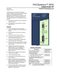
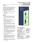
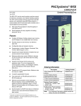
PACSystems™ RX3i CPU
IC695CPU310-CD with Firmware Version 3.00
Note:
This document contains information that is not available in any other publication;
therefore, we recommend that you read and save it for future reference.
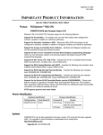
This is an update to the CPU firmware. The following new features have been added:
Support for the new RX3i PROFIBUS Slave module (IC695PBS301)
Support for the new RX3i non-isolated analog modules (IC695ALG616,
IC695ALG608, IC695ALG708, IC695ALG704)
Support for the new RX3i multi-use power supply (IC695PSD140). See Important
Product Information, GFK-2377 for detailed instructions on the installation and
application of these power supplies.
Support for Series 90-30 Temperature Control modules (IC693TCM302/303)
Support for Series 90-30 Power Transducer modules (IC693PTM100/101)
Addition of %AQ to possible I/O interrupt trigger memory types
Ability for user to interrupt Flash Read, Write, and Clear Operations
NOTE to users of IC69*MDL660 and IC69*MDL754 modules: Revision –A (version 1.00)
of these modules IS INCOMPATIBLE with IC695CPU310-CD. Revision –A modules must
be updated to Revision –AB (version 1.10) prior to use with IC695CPU310–CD. DO NOT
use a system that contains an IC694CPU310-CD and any IC69*MDL660-A or
IC69*MDL754-A modules.
For problems resolved in release 3.00, see page 4.
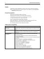
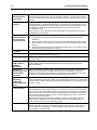
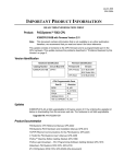
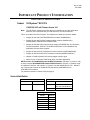
Version Identification
Hardware Identification
Firmware Identification
Catalog Number
Circuit Board ID
Firmware ID
Version
IC695CPU310-CD
CP4A1
CPU Primary
3.00 Build 12A1
BOC Rev 0104 Build 03A1
CPU Boot
2.50 Build 25A3
CPU Programmable Parts
Part ID
Revision
BIOS
f4_r05
MCU
r07/6/04
FPGA
X05
SDRAM CPLD
C
HW rev EPROM
f4_r05
MAC EPROM
f4_r05
2
Important Product Information
GFK-2329F
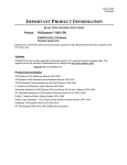
Updates
IC695CPU310 is field-upgradeable to firmware version 3.00 by ordering the upgrade kit
below or downloading it from the services web site. The hardware is not field upgradeable.
Upgrade Kit: 44A752290-G04
Product Documentation
PACSystems CPU Reference Manual, GFK-2222
PACSystems RX3i Hardware and Installation Manual, GFK-2314
TCP/IP Ethernet Communications for the PACSystems, GFK-2224
C Toolkit for PACSystems User’s Manual, GFK-2259
Proficy™ Machine Edition Getting Started, GFK-1868
Proficy Logic Developer – PLC Programming Software Getting Started, GFK-1918
Datasheet, PACSystems RX3i CPU, GFK-2316 (existing revision)
IPI, PACSystems RX3i CPU, GFK-2329F (this document)
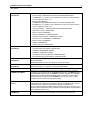
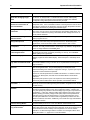
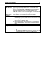
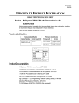
CPU Functional Compatibility
Subject
Description
Programmer Version
Requirements
Proficy® Machine Edition Logic Developer 5.0 or later must be used to configure and
program the RX3i. Service Pack 3 is required to support the new features in PACS
3.00.
C Toolkit Compatibility
The C Toolkit for PACSystems is distributed with Proficy® Machine Edition Logic
Developer 5.0 or greater. Toolkit build 50A1 or later is required for use with the RX3i.
Please note: The Series 90 Toolkit (IC641SWP709/719) is not compatible with
PACSystems.
Series 90-30 Module
Compatibility
The following Series 90-30 modules are supported by the PACSystems RX3i:
Discrete Input Modules:
IC693ACC300, IC693MDL230/231/240/241/632/634/645/646/648/654/655
Discrete Output Modules:
IC693MDL310/330/340/390/730/731/732/733/734/740/741/742/748/752/753/760/9
30/931/940
Discrete Combinational: IC693MAR590, IC693MDR390
Analog I/O Modules: IC693ALG220/221/222/223/390/391/392/442
High Speed Counter: IC693APU300
FANUC I/O Link: IC693BEM320, IC693BEM321
Motion Control: IC693DSM314, IC693DSM324
GENIUS: IC693BEM331
Serial IO Processor: IC693APU305
Temperature Control: IC693TCM302, IC693TCM303
Power Transducer: IC693PTM100, IC693PTM101
All other Series 90-30 modules are currently not supported.
Important Product Information
3
GFK-2329F
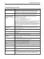
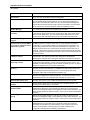
IC694 (blue) Module
Compatibility
IC695 (PCI) Module
Compatibility
Discrete Input Modules:
IC694ACC300, IC694MDL230/231/240/241/632/634/645/646/654/655
IC694MDL660 – To operate in a CPU Release 3.0 system, the module firmware
must be updated to version 1.10
Discrete Output Modules:
IC694MDL310/330/340/390/732/734/740/741/742/752/753/930/931/940
IC694MDL754 – To operate in a CPU Release 3.0 system, the module firmware
must be updated to version 1.10
Analog I/O Modules: IC694ALG220/221/222/223/390/391/392/442
High Speed Counter: IC694APU300
Motion Control: IC694DSM314
Expansion Backplanes: IC694CHS392/398
Expansion Power Supplies: IC694PWR321/330/331
FANUC I/O Link: IC694BEM320, IC694BEM321
Motion Control: IC694DSM324
GENIUS: IC694BEM331
Serial IO Processor: IC694APU305
Ethernet Interface: IC695ETM001
Universal Analog Input Module: IC695ALG600
PROFIBUS: IC695PBM300 (Master)
PROFIBUS: IC695PBS301 (Slave)
Non-isolated Analog Input Modules: IC695ALG616/608
Non-isolated Analog Output Modules: IC695ALG708/704
Series 90-30 Expansion Rack
Compatibility
Series 90-30 expansion racks, both local and remote, are supported by the
PACSystems RX3i.
PACSystems RX3i CPU does not operate in a Series 90-30 Rack.
Series 90-30 Main Rack
Compatibility
Series 90-30 Main Racks cannot be used in a PACSystems RX3i system.
Series 90-30 CPUs do not operate in PACSystemsRX3i Racks.
Isolated 24V power
In applications that use the IC69xALG220/221/222, consult PACSystems RX3i
Hardware and Installation Manual, GFK-2314 for details of wiring the 24V power.
In Release 3.0, the behavior of the COMMREQ fault output on a COMMREQ sent to
the PROFIBUS master module IC695PBM300 has been changed to be compatible
with the Series 90-30 CPU366 PROFIBUS Master. Previously, the fault output is
enabled when the module receives a COMMREQ and it is busy. Now, the busy
condition does not result in the fault output enabled.
COMMREQ to PBM300
Recommended IC200ALG240
revision
Configuration of
IC694MDL754
When a VersaMax™ system Genius® Network Interface Unit (IC200GBI001)
interoperates with a Genius Bus Controller located in a PACSystems PLC, and the
VersaMax system contains an IC200ALG240 Analog Input Module, it is
recommended to update the IC200ALG240 firmware to Revision 1.10 or later. Use
firmware update kit 44A752313-G01, available in Knowledge Base Article i023269 at
http://globalcare.gefanuc.com.
Always configure 16 bits of module status when using this module. Configuring 0 bits
of module status will result in invalid data in the module’s ESCP status bits.
4
Important Product Information
GFK-2329F
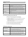
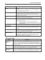
Problems Resolved by Version 3.00
Subject
Description
Avoid Ethernet module resets
Resetting the Ethernet module, either by Service Request 24 or by the restart
pushbutton, will cause some of the PLC CPU’s internal memory to be consumed if
EGD is configured. The problem becomes more pronounced with larger EGD
configurations. Power-cycling the system will recover the internal memory.
Nuisance faults at power-up
If the programmer is attempting SNP communications while the PLC is powering up,
sometimes non-critical software event faults appear in the PLC fault table.
Faults possible when power
cycling or hot-swapping
Series 90-30 smart modules in
an RX3i
When power is cycled on a rack in a system containing a Series 90-30 smart option
module or if the module is hot-swapped in an RX3i rack, the module may
intermittently fail in one of three ways:
There is a "loss of module" fault,
There is a "System Configuration Mismatch" fault, or
There is an "Unsupported hardware" fault.
In all three cases, the module will not be scanned until power is cycled on the module.
In the latter two cases, the PLC fault table must be cleared before the PLC can be
placed into RUN mode. These failures are much less likely if the module is in the
main RX3i rack or if the module is in an expansion rack and only the expansion rack
power is cycled. If operation of the module is critical in the application, then the user
logic should monitor the fault locating reference for the module, as described in
Chapter 14 of GFK-2222.
Avoid moving switch to STOP
during power -up
If the RUN/STOP switch is in RUN when power is initially applied, and moved to
STOP before power-up is complete, the PLC will go to RUN mode momentarily
before entering STOP mode.
Power-up in over-temperature
condition
Re-applying power to a PLC that has already detected that operating temperatures
have been exceeded may result in PLC CPU LEDs blinking an error code and loss of
memory contents.
Modbus RTU parity errors
In the case of an incoming message that contains a parity error, the message should
be dropped.
Repeated downloads
Many repeated downloads of configuration via Ethernet communication may
eventually result in Ethernet exception log event 28/9.
Memory types for PBM300
COMMREQ
In a PBM300 COMMREQ request, the COMMREQ response reference memory area
is indicated in the request. Discrete reference memory types are now supported for
the response data area.
PBM300 DPV1 Status data
When a slave module sends a DPV1 Alarm Request to the PBM300 master, the
alarm information is displayed in the DPV1 Status input area. The Sequence Number
field in this status area no longer indicates only the value 0.
Expanded fault information
Fault table entries for the IC694MDL754 and IC594MDL660 now contain specific
reference address and point address information.
Hot swap in Run I/O Disable
Mode
Addition of an IC694MDL754 while the PLC is in Run I/O Disabled mode does not
produce the expected “Addition of Module” fault.
Nuisance Fault
The fault "Non-critical CPU software event -- serial port event" may appear at powerup.
Some summary fault bits not
set
The summary fault %SC bits may not be set for certain conditions (%SC10 and
%SC12 for overtemperature or power supply fault; %SC9, %SC1, %SC13 for terminal
block)
Winloader update to incorrect
slot
Performing an Ethernet module firmware update but specifying the incorrect slot
number puts the PLC CPU into a state that requires power cycling with the battery
removed.
COMMREQ interface change
In previous releases, the fault output was enabled when the IC695PBM300 module
received a COMMREQ and it was busy. Now, the busy condition does not result in
the fault output enabled, compatible with the Series 90-30 CPU366 PROFIBUS
Master.
Important Product Information
5
GFK-2329F
Subject
Description
Mismatch fault no longer fatal
If the PLC detects a system configuration mismatch with a module, the fault it logs is
no longer fatal, but rather it is informational. This applies to GBC and
IC694MDL660/754.
Short circuit fault grouping
Module IC694MDL754 short circuit faults were previously handled in groups (two
groups 1-6, 17-32). If a second short circuit fault occurred within a group, it was not
reported to the fault table until the first fault within the group was cleared.
Module status
If the firmware on the IC694MDL660 or 754 becomes corrupt (e.g. a firmware update
is abruptly terminated prior to completion), no “loss of module” will be reported.
PLC CPU Communications
stops
After many, many repeated attempts to read or write bit memory using an erroneous
set of {segment selector, offset, length}, the PLC CPU will stop responding to any
serial and Ethernet communications.
PBM300 system configuration
mismatch faults
Following a store of invalid parameters in a PBM300 configuration, “System
Configuration Mismatch” faults may continue to occur even after the parameters are
corrected.
Checksum SVC_REQ
Service Request 6 Change/Read Number of Words to Checksum previously
interpreted its parameter as a byte count. It now interprets the parameter as a word
count. However, see “Service Request 6: rounding of length parameter” on page 8.
New CPU Features and Enhancements in Release 3.00
The RX3i CPU provides the following new features and enhancements:
Support for the new RX3i PROFIBUS Slave module (IC695PBS301)
Support for the new RX3i non-isolated analog modules (IC694ALG616, IC694ALG608,
IC694ALG708, IC694ALG704)
Support for the new RX3i multi-use power supply (IC695PDS140). See Important
Product Information, GFK-2377 for detailed instructions on the installation and
application of these power supplies.
Support for Series 90-30 Temperature Control modules (IC693TCM302/303)
Support for Series 90-30 Power Transducer modules (IC693PTM100/101)
Addition of %AQ to possible I/O interrupt trigger memory types
Ability for user to interrupt Flash Read, Write, and Clear Operations
CPU Restrictions and Open Issues
Subject
Description
Ethernet Disconnect During
Word-for-Word Change
If the Ethernet connection is broken during a word-for-word change, the
programmer may not allow a subsequent word-for-word change after reconnecting
due to the fact that it thinks another programmer is currently attached. If this
occurs, you should go offline and then back online again.
Simultaneous Clears, Loads and
Stores Not Supported
Currently, PACSystems CPUs do not support multiple programmers changing
CPU contents at the same time. The programming software may generate an error
during the operation. Simultaneous loads from a single PLC are allowed.
Power Cycle During Online Edit
If the user stores a folder to flash that is configured to power up from flash and
then subsequently power is cycled in the middle of a Online Edit session, the
programmer will still indicate that the Online Edit session is in progress after the
power cycle. The user should cancel the Online Edit session to continue.
Power Cycle During Write to
Flash
If the CPU is power cycled during the process of writing to flash, and is configured
to power up from flash, a fault will be generated on power up.
6
Important Product Information
GFK-2329F
Subject
Description
Hardware Configuration Not
Equal After Changing Target
Name
If the user stores a hardware configuration to flash that sets “Logic/Config Power
up Source” to “Always Flash” or “Conditional Flash” and then subsequently
changes the name of the target in the programming software, the hardware
configuration will go Not Equal and will not Verify as equal.
PLC and IO Fault Tables May
Need to be Cleared Twice to
Clear Faulted State
Both PLC and IO fault tables may need to be cleared to take the CPU out of
Stop/Fault mode. If one of the tables contains a recurring fault, the order in which
the tables is cleared may be significant. If the CPU is still in Stop/Fault mode after
both tables are cleared, try clearing the fault tables again.
Setting Force On/Off by Storing
Initial Value
Once a force on or force off has been stored to the PLC, the user cannot switch
from force on to force off or vice-versa directly by downloading initial values. The
user can turn off the force by doing a download, and then change the force on or
off by another download.
Number of Active Programs
Returned as Zero
The SNP request Return Controller Type and ID currently returns the number of
active programs as zero.
Serial I/O Failure at 115K During
Heavy Interrupt Load
Rare data corruption errors have been seen on serial communications when
running at 115K under heavy interrupt load on the PLC. Under heavy load
applications, users should restrict serial communications to 57K or lower.
RAND_MAX and rand() Function
Incompatible
In the C Toolkit, the RAND_MAX system variable is defined as a 32-bit integer.
However, the rand() function returns a 16-bit integer. By definition, rand() should
return an integer between 0 and RAND_MAX.
Incorrect Commreq Status For
Invalid Program Name
The program name for PACSystems is always "LDPROG1". When another
program name is used in a commreq accessing %L memory, an Invalid Block
Name (05D5) error is generated.
SNP ID not always provided
Unlike the Series 90-30, the RX3i CPU’s SNP ID will not appear in the Machine
Edition programmer Show Status display. Service Request 11 will always return
zeros.
Second programmer can change
logic while in Test & Edit mode
While currently active in a Test and Edit session using Machine Edition on one
PC, Machine Edition running on another PC is not prevented from storing new
logic to the PLC.
FANUC I/O Master and Slave
operation
Scansets on the master do not work properly for the first operation of the scanset
after entering RUN mode. They do work properly for subsequent scans.
After downloading a new hardware configuration and logic, a power cycle may be
required to resume FANUC I/O operation.
Use PLCs of similar performance in FANUC I/O networks. If a master or slave is
located in an RX3i system, the other PLCs should be RX3is or Series 90-30
CPU374s.
Repeated power up/down cycles of an expansion rack containing FANUC I/O
slaves may result in failure of the slaves’ operation, with the RDY LED off.
Must Have Logic If Powering-Up
From Flash
If the application will configure the CPU to retrieve the contents of flash memory at
power-up, be sure to include logic along with hardware configuration when saving
to flash memory.
CPU may not detect low-battery
condition
PACSystems CPUs may not detect a low-battery condition early enough to
provide a meaningful warning to the user to replace the battery. A battery with
very low capacity may still have a terminal voltage high enough to report that it is a
good battery. In this case, when the battery starts supplying the memory power
(battery backup), the battery voltage would quickly drop to unacceptable levels,
with little warning to the user before failure. To insure against data loss, users
should replace batteries in accordance with the guidelines provided in the CPU
Reference Manual, GFK-2222. Additionally, users could save logic and hardware
configuration to flash.
Two loss of module faults for
Universal Analog Module
Occasionally, the hot removal of the Universal Analog Input Module
(IC695ALG600) results in two “Loss of I/O Module” faults instead of one.
Power up of HSC may take as
long as 20 seconds
As power is applied to a 90-30 High-Speed Counter, the "module ready" bit in the
status bits returned each sweep from the module may not be set for as long as 20
seconds after the first PLC sweep, even though there is no "loss of module"
indication. I/O data exchanged with the module is not meaningful until this bit is
set by the module. c.f., pages 4-3 to 4-5 of GFK-0293C.
Important Product Information
7
GFK-2329F
Subject
Description
Lost count at power up for Serial
IO Processor
The serial IO Processor (IC693APU305) will lose the first count after every power
up or every time the module receives a configuration.
Info fault at power up
Intermittently during power-up, an Informational non-critical CPU software fault
may be generated with fault extra data of 01 91 01 D6. This fault will have no
effect on the normal operation of the PLC. But, if the hardware watchdog timer
expires after this fault and before power has been cycled again, then the outputs
of I/O modules may hold their last state, rather than defaulting to zero.
Serial Port Lock-up after Bad
Modbus Message
If a badly formed Modbus RTU message is sent to the PLC, the serial port will lock
up. Power must be cycled to recover proper port operation.
Timed interrupt response time
increased
A GBC in the system may impact response time for timed interrupts. The worst
case interrupt response time for a PLC system with a GBC and no other Genius
devices is 0.5 milliseconds. The worst case interrupt response time for a PLC
system with a GBC and maximum amount of Genius data is 50 milliseconds.
Extended Memory Types for IO
Triggers
%R, %W and %M cannot be used as IO triggers.
Possible Machine Edition
disconnect when multiple GBCs
are present in expansion/remote
racks within a system.
If a system contains multiple GBCs in expansion/remote racks, then it is possible
for ME to timeout its connection to the PLC on a clear operation or a store of
configuration. For each GBC located in an expansion/remote rack there is a 3
second delay added to the time required for a clear/store of configuration. The
default connection timeout is 10 seconds and the default request timeout is 16
seconds. These values should be increased by at least 3 seconds per each GBC
physically located in an expansion/remote rack. This is true for both Ethernet and
serial connections.
Possible Machine Edition
inability to connect
Infrequently, an attempt to connect a programmer to a PLC via Ethernet will be
unsuccessful. The normal connection retry dialog will not be displayed.
Rebooting the computer that is running the programmer will resolve the behavior.
Repeated store of folder
containing C blocks
After many stores of a folder that contains C blocks, the PLC CPU and/or Ethernet
module may cease operation. Power-cycle the main PLC rack to recover. The
possibility of undesired operation may be avoided completely by power-cycling the
th
main PLC rack after every 5 store of a C block folder.
Power supply overtemperature
reporting
If an RX3i power supply detects an overtemperature condition, the reported fault
specifies group 24 and results in the %SA0008 OVR_TMP bit being set and the
user’s configured fault action being executed. This fault group and bit are
intended to reflect CPU overtemperature conditions only.
SNP Update Datagram message
If an Update Datagram message requests 6 or less bits or bytes of data, the PLC
will return a Completion Ack without Text Buffer. The protocol specifies that the
returned data will be in the Completion Ack message, but it may not be.
GBC30 may not resume
operation after power cycle
In rare instances, a GBC30 in an expansion rack may not resume normal
operation after a power cycle of either the expansion rack or the main rack.
Configuration of third-party
modules
Do not specify a length of 0 in the configuration of a third-party module. The
module will not work properly in the system.
Power supply status after CPU
firmware update
The PLC will report a “Loss of or missing option module” fault for the
IC695PSD140 RX3i power supply following an update of PLC CPU firmware.
Also, the slot will appear empty in the programmer’s online status detail view. The
power supply continues to operate normally. Power cycle to restore normal status
reporting.
Power supply status after power
cycling
Rarely, turning a power supply on or off may not result in an add or loss fault.
Also, the slot will appear empty in the programmer’s online status detail view. The
power supply continues to operate normally. Power cycle to restore normal status
reporting.
Configuration store failure
Repeated stores of a configuration that contains serial bus transmitter module
IC695LRE001 to a system that does not physically contain the module will
eventually result in failure of the store attempt. Power cycle the main rack to
restore normal operation. Removing the non-present module from the
configuration will eliminate the possibility of the behavior.
8
Important Product Information
GFK-2329F
Subject
Description
“Clear All” operation may
timeout
A Clear All to a system with a very large hardware configuration may timeout, with
the error:
Error 8097: Server Error - Transfer Error: Host driver timed out. [0x6A][0x01]
The selected memory could not be cleared
ME does not disconnect when the error occurs and a retry is usually successful.
Don’t use multiple targets
In a system in which the hardware configuration is stored from one target and logic
is stored from a different target, powering-up from flash will not work. The
observed behavior is that, following a power up from flash, ME reports hardware
configuration and logic "not equal".
Missing “Loss of terminal block”
fault
The IC695ALG600/608/616 analog input modules do not produce a “Loss of
terminal block” fault when hardware configuration is stored or the module is hotinserted, and the terminal block is not locked into place.
Sequence Store Failure
In systems with very large hardware configurations, it is possible to encounter a
“PLC Sequence Store Failure” error when writing the configuration to flash. To
work around this error, either:
1. Perform an explicit clear of flash prior to performing the write.
2. Increase the operation timeout used by Machine Edition software prior to
performing the write.
IC694MDL754: Must configure
module status bits
Always configure 16 bits of module status when using this module. Configuring 0
bits of module status will result in invalid data in the module’s ESCP status bits.
Service Request 6: rounding of
length parameter
Processing for Service Request 6 Change/Read Number of Words to Checksum
incorrectly rounds the specified length to the next largest multiple of 8 bytes, rather
than 8 words. Consequently, each sweep may checksum fewer words than
expected.
PID Algorithm
See “Documentation Errata” on page 14. For the case that bit 2 is set to 1 and bit
0 is set to 1, the product will operate in a manner opposite the description. The
derivative term is added when it should be subtracted.
IC695ALG600 Lead Resistance
Compensation setting
A configuration store operation will fail if a channel is configured for 3-wire RTD
and Lead Resistance Compensation is set to Disabled. A Loss of Module fault will
be logged in the I/O Fault table at the end of the store operation. To recover the
lost module, the configuration must be changed to enable Lead Resistance
Compensation and module must be power cycled.
CPU Operational Notes
Subject
Description
Important Installation
Instructions for
Battery
A battery is shipped with the CPU unit behind the battery door on the faceplate but it is not
connected. Do not connect the battery until the CPU is installed in the rack and the rack
powered on. The battery may then be attached to either of the two terminals in the battery
compartment. Once that is done, the CPU may be powered down and normal battery back
up operation will begin. To save battery life, do not connect the battery for the first time until
the CPU is powered up.
LD-PLC operations
Machine Edition LD-PLC no longer supports a function which connects to the PLC,
downloads, then disconnects from the PLC. The connect and download functions are now
separate. To perform a download to the PLC, you must first connect to the PLC.
Logic Executed in
Row Major Instead of
Column Major
Logic execution in PACSystems RX3i is performed in row major order (similar to the Series
90-30). This is different from the Series 90-70, that executes in column major order. This
means that some complicated rungs may execute slightly differently on PACSystems RX3i
and Series 90-70. For specific examples, see the programming software on-line help.
Important Product Information
9
GFK-2329F
Slot numbering,
power supply
placement, CPU
placement and
reference
1.
The A/C Power-Supply (IC695PSA040) for the RX3i is a doublewide module whose
connector is left justified as viewed when installed in a rack. It cannot be located in Slot
11 of a 12-slot rack nor Slot 15 of a 16-slot rack. No latch mechanism is provided for the
last (right-most) slot in a rack, therefore it is not possible to place the power-supply in the
second to last slot.
2. The RX3i CPU (IC695CPU310) is a doublewide module whose connector is right
justified as viewed when installed in a rack. It is referenced for configuration and by user
logic applications by the leftmost slot that it occupies. For example, if the RX3i CPU has its
physical connector inserted in to slot 4, which means it occupies slots 3 and 4, the CPU is
referenced as being located in slot 3. The referenced location of the CPU is not
determined by what slot the physical connector is located in, but rather by the left most slot
occupied by the entire module.
3. Due to item #2 above, the RX3i CPU may be located in Slot 0 of a rack (physical
connector in Slot 1). In addition the CPU cannot be located in Slot 11 of a 12-slot rack nor
Slot 15 of a 16-slot rack, since doing so would require the physical connector to be located
in the slot reserved for an expansion module.
4. When migrating a Series 90-30 CPU system to a PACSystems RX3i CPU, be aware
that to maintain the Slot 1 location of the CPU, only a singlewide power-supply may be
used in Slot 0. Either DC power supply can be used (IC695PSD040 or IC695PSD140).
Therefore, if the application using an existing Series 90-30 system must maintain a Slot 1
CPU and uses an AC power-supply, the RX3i system must have the RX3i AC powersupply located in a slot to the right of the RX3i CPU in Slot 1.
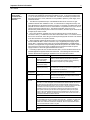
5. In deciding to place the CPU in slots other than Slot 1, the user should be aware of the
possible application migration issues that could arise. The following lists the areas that
could be affected when migrating an application from one CPU slot to another.
Item Affected
User Logic
How Affected
Service Request #15
(Read Last-Logged
Fault Table Entry)
Service Request #20
Location of CPU faults will not be the standard 0.1
location, but will reflect the slot the CPU is located in.
User logic that decodes fault table entries retrieved by
these service requests may need updating.
(Read Fault Tables)
Communications
Request (Commreq)
Commreqs directed to the CPU (e.g. those directed to
the serial ports of the CPU) will need to be updated with
the correct CPU slot reference.
H/W
Configuration
CPU Slot location
Slot location of the CPU must be updated in the HW
Configuration to reflect the CPU’s true location.
Fault Tables
Faults logged for the
CPU
The location of faults logged for the CPU in the fault table
will not be the standard 0.1 (rack.slot) location, but will
reflect the CPU’s actual slot.
External
Devices
Series 90 PLCs
Remote Series 90 PLCs that use SRTP Channels COMMREQs expect the CPU to
be in slot 1. In order to support communications with Series 90 SRTP clients such
as Series 90 PLCs using SRTP Channels, the RX3i internally redirects incoming
SRTP requests destined for {rack 0, slot 1} to {rack 0, slot 2}, provided that the CPU
is located in rack 0 slot 2 (and the remote client has not issued an SRTP
Destination service on the connection to discover the rack and slot of the CPU).
This special redirection permits Series 90-30 applications that expect the power
supply to be located leftmost and the CPU to be located to the right of the power
supply to function. Attempts to establish channels with CPUs in slots other than 1
or 2 will fail if initiated from Series 90 PLCs.
HMI and External Communication Devices
All external communication devices that interact with the CPU should be checked
for compatibility with CPU slot locations other than slot 1. Problems may arise with,
but are not limited to, initial connection sequences and fault reporting. Machine
Edition View customers should select “GE SRTP” as their communications driver –
it can communicate with a CPU in any slot.
Host Communications Toolkit (HCT)
Applications that utilize the Host Communications Toolkit may require updated
drivers.
10
Important Product Information
GFK-2329F
NaN handled
differently than in
Series 90-30
The PACSystems RX3i CPU may return slightly different values for Not A Number as
compared to Series 90-30 CPUs. In these exception cases (e.g., 0.0/0.0), power flow out of
the function block is identical to Series 90-30 operation and the computed value is still Not A
Number.
PID Algorithm
Improved
The PID algorithm used in PACSystems has been improved and therefore PID will function
slightly differently on PACSystems RX3i than on the Series 90-30. The differences are that
the elapsed time is computed in 100 µS instead of 10 mS units. This smoothes the output
characteristic, eliminating periodic adjustments that occurred when the remainder
accumulated to 10mS.
Also, previous non-linear behavior when the integral gain is changed from some value to 1
repeat/second was eliminated.
Some Service
Requests different
from 90-30 or no
longer supported
Service Requests 6, 15, and 23 have slightly different parameters. Refer to GFK-2222.
PACSystems PLCs support Service Request 26/30 functionality via fault locating
references.
Service Request 13 requires a valid value in the input parameter block (Refer to GFK2222 for details). On the Series 90-30 and Series 90-70 the parameter block value was
ignored.
Service Requests 48 and 49 are no longer supported (there is no auto-restart) because
most faults can be configured to be not fatal.
IL and SFC
IL and SFC are not available.
DO I/O Instruction
The Series 90-30 Enhanced DO I/O instruction is converted to a standard DO I/O instruction
(the ALT parameter is discarded and ignored.)
END Instruction
The Series 90-30 END instruction is not supported. Alternate programming techniques
should be used.
Non-nested JUMP,
LABEL, MCR, &
ENDMCR
Instructions
Non-nested JUMPs, LABELs, MCRs, & ENDMCRs are translated to the corresponding
nested JUMPs, LABELs, MCRs, & ENDMCRs when converting from Series 90-30 to
PACSystems RX3i.
Changing IP
Address of Ethernet
Interface While
Connected
Storing a hardware configuration with a new IP address to the RX3i while connected via
Ethernet will succeed, then immediately disconnect because the RX3i is now using a
different IP address than the Programmer. You must enter a new IP address in the Target
Properties in the Machine Edition Inspector window before reconnecting.
Duplicate Station
Address for
Modbus Will
Conflict with Other
Nodes
The default serial protocol for the RX3i is Modbus RTU. The default Station Address is 1. If
the PLC is added to a multi-drop network, care must be taken that the PLC is configured with
a unique Station Address. Nodes with duplicate Station Addresses on the same network will
not work correctly.
Timer Operation
Care should be taken when timers (ONDTR, TMR, and OFDTR) are used in program blocks
that are NOT called every sweep. The timers accumulate time across calls to the sub-block
unless they are reset. This means that they function like timers operating in a program with a
much slower sweep than the timers in the main program block. For program blocks that are
inactive for large periods of time, the timers should be programmed in such a manner as to
account for this catch up feature.
Related to this are timers that are skipped because of the use of the JUMP instruction.
Timers that are skipped will NOT catch up and will therefore not accumulate time in the
same manner as if they were executed every sweep.
Constant Sweep
Constant Sweep time, when used, should be set at least 10 milliseconds greater than the
normal sweep time to avoid any over-sweep conditions when monitoring or performing online changes with the programmer. Window completion faults will occur if the constant
sweep setting is not high enough.
Important Product Information
11
GFK-2329F
Large Number of
COMM_REQs Sent to
Module in One Sweep
Causes Faults
A large number of COMM_REQs (typically greater than 8) sent to a given board in the same
sweep may cause Module Software faults to be logged in the PLC fault table. The fault
group is MOD_OTHR_SOFTWR (16t, 10h) and the error code is
COMMREQ_MB_FULL_START (2). When this occurs, the “FT” output of the function block
will also be set. To prevent this situation, COMM_REQs issued to a given board should be
spread across multiple sweeps so that only a limited number (typically 8 or less) of
COMM_REQs are sent to a given board in each sweep. In addition, the FT output parameter
should be checked for errors. If the FT output is set (meaning an error has been detected),
the COMM_REQ could be re-issued by the application logic.
C Block Standard
Math Functions Do
Not Set errno
In C Blocks, standard math functions (e.g. sqrt, pow, asin, acos) do not set errno to the
correct value and do not return the correct value if an invalid input is provided.
Upgrading Firmware
1.
2.
3.
The process of upgrading the CPU firmware with the WinLoader utility may fail when
multiple IO modules are in the main rack, due to the time it takes to power cycle the rack
system. If the upgrade process fails, move the CPU to a rack without IO modules and
restart the upgrade process.
Winloader initial connect baud rate is fixed at 19200 baud. Note that the firmware
download will occur at 115.2K baud by default.
Note that if you have hyperterm open on a port, and then try to use Winloader on the
same port, Winloader will often say “Waiting for Target” until the hyperterm session is
closed.
Hot Swap
Hot Swap of power supplies or CPUs is not supported in this release
Serial Port
Configuration
COMMREQs
With the following combination of circumstances, it is possible to render serial
communications with the CPU impossible:
1. User configuration disables the Run/Stop switch
2. User configures the power up mode to Run or Last
3. Logic is stored in FLASH and user configures CPU to load from FLASH on power
up
4. User application issues COMMREQs that set the protocol on both of the serial ports
to something that does not permit communications to the ME programmer.
12
Important Product Information
GFK-2329F
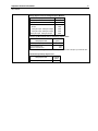
Performance Data
The following Performance Data for the IC695CPU310 was measured for this Release of the
PLC CPU firmware (Release 3.0). See Appendix A of the PACSystems CPU Reference
Manual, GFK-2222 for explanation of the data.
Base Sweep Times
CPU Mode
CPU310
Stop + I/O enabled
1086 µsec
Stop + I/O disabled
1076 µsec
RX3i I/O Module Types
Type
Part Numbers
Discrete Input (16 point)
IC694MDL240, IC697MDL241, IC694MDL645, IC694MDL646
Discrete Input (32 point)
Discrete Output (8 point)
IC694MDL654, IC694MDL655, IC697MDL654
IC694MDL330, IC694MDL732, IC694MDL930, IC694MDL940
Discrete Output
(16 point, 12 point)
IC694MDL340, IC694MDL341, IC694MDL740, IC694MDL741
Discrete Output (32 point)
IC694MDL350, IC694MDL340, IC694MDL752, IC694MDL753
Analog Input (4 Channel)
IC694MDL742, IC694MDL940
IC695ALG220, IC694ALG221
Analog Input (16 Channel)
IC694ALG222, IC694ALG223
Analog Output (2 channel)
IC694ALG390, IC394ALG391
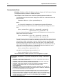
RX3i Module Sweep Impact Times
Note:
The base case provides the overhead for the case when a single module is present in the
rack. The increment (Inc) refers to the overhead for each similar module that is added.
CPU310 (µsec)
Main Rack
Main Rack
Expansion Rack
Main Rack
(Inc)
Expansion
Rack
Expansion Rack
(Inc)
Discrete Input 16 point
70
49
110
99
Discrete Input 32 point
92
64
129
118
Discrete Output 8 point
56
26
93
72
Discrete Output 16 point
55
24
94
72
Discrete Output 32 point
74
51
112
104
Discrete Mixed
8 point in/ 8 point out
124
90
194
170
Analog Input 4 channel
127
109
168
158
Analog Input 16 channel
429
409
554
542
Analog Output 2 channel
Universal Analog
IC695ALG600
96
72
164
158
-
153
N/A
N/A
-
143
N/A
N/A
-
153
N/A
N/A
-
181
N/A
N/A
-
158
N/A
N/A
New Modules:
Analog Input 8 channel
IC695ALG608
Analog Input 16 channel
IC695ALG616
Analog Output 4 channel
IC695ALG704
Analog Output 8 channel
IC695ALG708
Important Product Information
13
GFK-2329F
Sweep Impact Times for Intelligent Option Modules
Sweep Impact Item
CPU310 (µsec)
ETM (Peripheral Ethernet Module)
199
High Speed Counter
PROFIBUS Master
No I/O
100 bytes Input, 100 bytes Output
100 bytes Input, 200 bytes Output
200 bytes Input, 100 bytes Output
1091
1480
1580
1590
1660
I/O Interrupt Block Performance and Sweep Impact Times
Sweep Impact Item
CPU310
(µsec)
I/O interrupt sweep impact
127.8
Minimum response time
451.8
Typical response time
475.0
Maximum response time
602.7
Note that the minimum, typical, and maximum response times include a 300 µsec Input card filter time.
Timed Interrupt Sweep Impact Time
Sweep Impact Item
Timed interrupt sweep impact
CPU310
(µsec)
87.3
14
Important Product Information
GFK-2329F
Documentation Errata
GFK-2222, PACSystems RX7i CPU Reference Manual: Chapter 10, “PID Function,” Section
“PID Algorithm Selection (PIDISA or PIDIND) and Gains”
The description of the Derivation term should be replaced/augmented with this text:
The Derivative term is the time rate of change of the Error term in the interval since the
last PID solution.
Derivative = ∆Error / dt = (Error – previous Error) / dt,
where
dt = Current PLC elapsed time - PLC elapsed time at previous PID solution.
In normal mode (that is, without Reverse-Action mode), this is the change in the error
term.
(Error – previous Error) = (SP – PV) – (previous SP – previous PV)
= (previous PV – PV) – (previous SP – SP)
However, when the Reverse-Action mode bit in the Config Word is set, the sign of the
change in the error term is reversed.
(Error – previous Error) = (PV – SP) – (previous PV – previous SP)
= (PV – previous PV) – (SP – previous SP)
The change in the error term depends on changes in both the Set Point and the Process
Variable. If the Set Point is constant, the difference between SP and the previous SP is
zero and has no effect on the output. However, Set Point changes can cause large
transient swings in the derivative term and hence the output. Loop stability may be
improved by eliminating the effect of Set Point changes on the derivative term. Set the
third bit (bit 2) of the Config Word to 1 to calculate the Derivative based only on the
change in PV. For bit 2 set in normal mode (bit 0=0).
(Error – previous Error) = (previous PV – PV),
and with bit 2 set in Reverse-Action mode (bit 0 = 1),
(Error – previous Error) = (PV – previous PV).
For information about a related open issue, see “PID Algorithm” on page 8.
The following information is for products bearing the UL marking for Hazardous
Locations:
•
•
•
•
•
•
WARNING - EXPLOSION HAZARD - SUBSTITUTION OF COMPONENTS MAY IMPAIR
SUITABILITY FOR CLASS I, DIVISION 2;
WARNING - EXPLOSION HAZARD - WHEN IN HAZARDOUS LOCATIONS, TURN OFF
POWER BEFORE REPLACING OR WIRING MODULES; AND
WARNING - EXPLOSION HAZARD - DO NOT DISCONNECT EQUIPMENT UNLESS
POWER HAS BEEN SWITCHED OFF OR THE AREA IS KNOWN TO BE
NONHAZARDOUS.
EQUIPMENT LABELED WITH REFERENCE TO CLASS I, GROUPS A, B, C & D, DIV. 2
HAZARDOUS LOCATIONS IS SUITABLE FOR USE IN CLASS I, DIVISION 2, GROUPS A,
B, C, D OR NON-HAZARDOUS LOCATIONS ONLY
The tightening torque range for the control terminals is 9.6-11.5 in. lb. Use only wire rated
for 90°C. Be sure to observe any additional ratings that are provided with the modules.
Batteries: Replace Battery with Matsushita Part No. BR2477A Only. Use of another battery
may present a risk of fire or explosion.” “Caution, Battery may explode if mistreated. Do Not
recharge, disassemble or dispose of in fire”. The correct battery type is available as
Accessory Kit IC698ACC701.