1
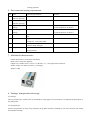
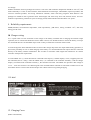
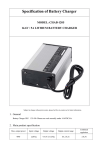
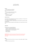
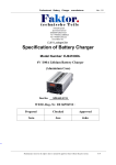
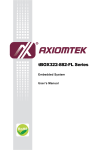
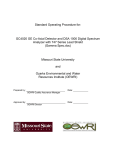
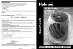
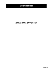
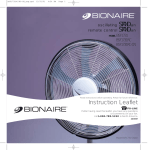
SONEIL
6033 Shawson Dr., Unit 29, Mississauga, Ontario, Canada L5T 1H8
Ph.: (905) 565-0360
Fax: (905) 565-0352
http://www.soneil.com
Revision No.: R02
Specification of Battery Charger
MODEL : 1240 SR
12V / 20A LEAD ACID BATTERY CHARGER
Subject to change without prior notice, please feel free to contact us for latest information.
1. General
Battery Charger 1240SR is cooled by 250*150*88mm 12VDC ball-bearing fans with forced air, can work
normally under 14.7Vdc/20A and with reverse polarity protection.
2. Main product specification
Max. output power
Input voltage
Output voltage
Output current range
Combined regulation
305W
115Vac/230Vac
+14.7+/-0.2Vdc
19.5-20.5A
+/-0.2V
3. Environmental condition
No.
Item
Technical specification
Remark
1
Humidity
5~95%
With package
2
Altitude
≤3000m
Work normally
3
Cooling
The power supply is cooled by 250*150*88mm
12VDC ball-bearing fans forced air
Working under full
load
4. Electrical characteristics
4.1 Input characteristic
No.
Item
Technical specification
Remark
1
Rated input voltage
115/230Vac
2
Input voltage range
90~132/180~264Vac
115Vac/230Vac
selector switch
3
AC input voltage frequency
47~63Hz
4
Max input current
3.8A
Vin=90Vac, rated load
4.2 Output characteristic
No.
Item
Technical specification
1
Fast charge voltage
14.7+/-0.2Vdc
2
Floating voltage
13.8Vdc
3
Constant current
20A
4
Switch current
4.0A
5
Power efficiency
≥80%
Vin=230Vac, rated load
6
Output inhibit voltage
13.7~14.0V
7
Output
50~100mA
For powering electric vehicle
controller only
inhibit current
Remark
4.3 Protection characteristics
No.
Item
Technical specification
1
Over voltage protection
2
Software over voltage protection
The charger software limits the maximum
output voltage to a level suitable for the
connected battery system
3
Thermal protection
An internal temperature monitor reduce
charger output power in extreme operational
temperature to prevent damage
4
Current limiting protection
22A
Remark
At CC mode
5
Short circuit protection
Short
circuit
protection
should
be
automatically recovery after remove the
condition
6
Reverse polarity protection
If output wires are reversely connected the
charger will not operate and will work
normally when wires are correctly connected.
7
Fan cooling
The fan is controlled by a temperature sensor.
After charger works , the fan will run for 2min
or so ( even several seconds);
if the charger temperature is below 30~45 ℃,
the fan will stop; if the charger temperature
rise, the fan will run again;
4.4 Charging indicator
No.
Item
Status
Remark
1
Power on
LED1: red
2
Charging
LED2: OFF
3
Fully charged
LED2: green
4
Charge voltage
LCD display
Select switch at V position
5
Charge current
LCD display
Select switch at A position
6
Completely charged
Charge current is very low(down to 0A)
Select switch at A position
Standard( or test condition)
Remark
No breakdown
5. Safety & EMC
No.
Item
1
Electric
strength test
Input-output
1500Vac/10mA/1min
2
Isolation
resistance
Input-ground
≥10Mohm@500Vdc
Output-ground
≥10Mohm@500Vdc
3
Leakage current
<3.5mA
4
Safety
CE/ UL compliant
5
EMC
EN55022:1998+A1:2000+A2:2003
EN55024:1998+A1:2001+A2:2003
(EN61000-4-2:1995+A1:1998+A2:2001
EN61000-4-3:2002
EN6100-4-4:1995+A1:2000+A2:2001
EN61000-4-5:1995+A1:2000
EN61000-4-6:2001
EN61000-4-11:2001)
6
LVD
EN60335-1:2002+EN60335-2-29:2002
Vin=264Vac
Remark: Discrimination A- Function OK under technical requirement range;
Discrimination B- Function temporarily debasement without reposition and halt is allowed;
Discrimination R – Physical damage or failure of equipment are not allowed, but damage of protection
device (fuse) caused by interference signal of outside is allowed, and the whole
equipment can work normally after replacement of protection device and reset of
running parameter
6. Environmental testing requirements
No.
Item
Technical specification
Remark
1
High temperature
ambient operating
+40℃
Features ok
2
Low temperature
ambient operating
-10℃
Features ok
3
High temperature
storage
+70℃
Work normally after recovery under
normal temperature for 2hours
4
Low temperature
storage
-40℃
Work normally after recovery under
normal temperature for 2hours
5
Random vibration
20Hz to 2000Hz 3Grms 20hours per
axis
6
Repetitive shock
40g peak 3 orthogonal axes, 3+ and 3in each axis, 11ms pulse width
7
Thermal shock
-35℃ to 75℃, < 3min transition,
2.5hours dwell, 200cycle
8
Drop test
BS EN60068-2-32:1993 TEST ED: free
fall appendix B
7. Mechanical characteristics
Outline dimension: L*W*H=250*150*88mm
Input socket: meets IEC standard;
Output wire: 10AWG, 4mm2, brown (+ve) & blue (-ve), 1.5m length; thick insulation
Inhibit voltage wire: AWG18 yellow; 1.5m length;
Weight: 3.6Kg
8. Package, transportation & storage
8.1 Package:
There is product name, model, name of manufacturer, safety approval, serial number, User Manual and packing list in
the package box
8.2 Transportation:
Suit for transportation by truck, ship and plane, the products should be shielded by tent from sunshine, and loaded
and unloaded carefully.
8.3 Storage:
Products should be stored in package box when it is not used. And warehouse temperature should be -40~70℃, and
relative humidity is 5~95%. In the warehouse, there should not be harmful gas, inflammable, explosive products, and
corrosive chemical products, and strong mechanical vibration, shock and strong magnetic field affection. The
package box should be above ground at least 20cm height, and 50cm away from wall, thermal source, and vent.
Under this requirement, product has 2years of storage period, and should be rechecked when over 2years.
9. Reliability requirements
MTBF(standard, environmental temperature, load requirement) ≥50K hours; testing condition: 25℃, full load,
testing proved value.
10. Charger wiring
10.1 A spark often on first connection of the charge to the battery terminals due to charging the internal output
capacitors, this is normal and should not lead to undue concern, care should be taken to ensure the battery vent caps
are closed and there are no flammable object in the vicinity of where the connection will be made
10.2 The charger has been calibrated to take account of the voltage drop in the DC output cables during operation, to
prevent the possibility of over or under charging of the battery it is recommended the DC output cable are connected
directly to the battery without modification. We are able to customize cable length and connections for volume
customers with specific requirements.
10.3 The inhibit wire (+) cannot be tested or connected to the output (+) and the output(-) wires, it supplies power for
the controller(such as a relay). After the inhibit wire(+) is connected to the controller' terminal(+) and the charger
output(-) connected to the controller' terminal (-), the controller will work.. The inhibit wire provides a DC voltage of
13.7V ~ 14.0V and current of 50~100mA signal to the controller.When controller is connected to inhibit wire it will
shut off the electric circuit of the vehicle and prevents vehicle from moving during charging.
11.Label
12. Charging Curve
(Refer to attachment)