1
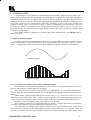
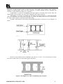
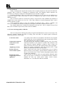
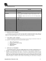
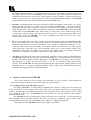
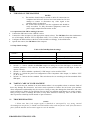
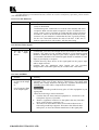
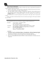
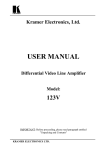
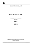
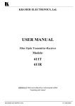
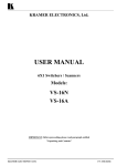
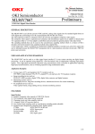
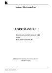
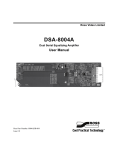
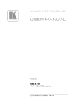
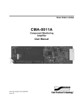
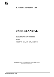
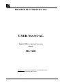
KRAMER ELECTRONICS Ltd.
USER MANUAL
Digital (SDI) to Analog Converter
Model:
SD-7401
IMPORTANT: Before proceeding, please read paragraph entitled
"Unpacking and Contents"
KRAMER ELECTRONICS LTD.
P/N: 2900-006002
Table Of Contents
Section Name
1
1.1
1.2
1.3
1.4
2
3
4
5
6
6.1
7
8
9
9.1
9.2
10
11
11.1
11.2
11.3
Page
INTRODUCTION
Digital and Analog Signals
Several Points to Consider when Working with Digital Signals
SDI Standards
Factors Affecting Quality of Results
SPECIFICATIONS
HOW DO I GET STARTED?
UNPACKING AND CONTENTS
OPTIONAL ACCESSORIES
SDI TO ANALOG CONVERTER
Getting to Know Your SD-7401 Converter
INSTALLATION
CONNECTING TO DIGITAL VIDEO DEVICES
TURNING ON THE MACHINES
Operation of the SDI to Analog Converter
Dip-Switch settings
TAKING CARE OF YOUR MACHINE
TROUBLESHOOTING
Power and Indicators
SDI and Video signals
Noise and Hum
Limited Warranty
2
2
2
4
4
5
5
5
5
6
6
7
7
7
8
8
8
8
9
9
9
10
List Of Illustrations
Figure
1
2
3
Page
Digital “eye” Diagram
The Digital “eye” after accumulating noise and jitter
SD-7401 Front/Rear Panel Features
3
3
7
List Of Tables
Table
1
2
Page
SD-7401 Front/Rear Panel Features
SD-7401 Dip Switch settings
KRAMER ELECTRONICS LTD.
7
8
1
1
INTRODUCTION
Congratulations on your purchase of this Kramer Electronics SDI / Analog converter. Since 1981,
Kramer has been dedicated to the development and manufacture of high quality video/audio equipment.
The Kramer line has become an integral part of many of the best production and presentation facilities
around the world. In recent years, Kramer has redesigned and upgraded most of the line, making the best
even better. Kramer’s line of professional video/audio electronics is one of the most versatile and
complete available, and is a true leader in terms of quality, workmanship, price/performance ratio and
innovation. In addition to the Kramer line of high quality distributors, such as the one you have just
purchased, Kramer also offers a full line of high quality switchers, processors, interfaces, controllers and
computer-related products.
This manual includes configuration, operation and option information for the SD-7401 SDI to
Analog converter
1.1 Digital and Analog signals
An analog signal varies continuously. It may have any value (within its physical bounds) and can
change at any instant. A digital signal is made up of a finite number of discrete levels, usually – but not
always – changing only at discrete time periods. An example of a digitized waveform is shown below.
ANALOG SIGNAL
DIGITAL SIGNAL
1.2 Several points to consider when working with digital signals
The minimum noise introduced by quantizing is 1 bit (1 level), so the higher the number of bits, the
lower the inherent noise, and the higher the resolution.
Since A/D and D/A conversions create artifacts, it is important not to convert back and forth. In a
“mixed” outfit, the video should be digitized, and all the digital processing done before converting back to
analog.
“Multi-media” systems usually quantize the video to 8 bits (i.e. 28 = 256) levels. Some “levels” are
dedicated to special codes (SAV, EAV – similar to syncs in analog video), leaving 220 quantization levels
(~3mV steps) for the luminance signals. Audio is usually quantized to 16 bits for multi-media systems.
Broadcast systems usually use 10-bit video, and 20- to 24- bit audio.
The advantages of working in a digital domain are obvious – a digital signal may be transported
very easily, and saved and retrieved reliably with no generation losses.
The transmission of a digital video signal is reliable up to a certain length of cable. Beyond this
length, the signal is destroyed. This phenomenon is known as the “cliff-effect”. To avoid the “crash” at
the cliff, an “equalizer and reclocker” should be inserted at a distance less than the “cliff” length. From
KRAMER ELECTRONICS LTD.
2
this point it is again possible to drive a cable up to the “cliff” length. This is similar to the “repeater”
analogy for analog signals. (Note: the term “equalizer” is usually dropped, and the “equalizer and
reclocker” is often referred to simply as a “reclocker”).
“Equalization” is a process of amplifying the input signal to overcome losses on the cable. For
digital signals, this is possible, since the correct amplitude of the signal is known!
“Reclocking” is a process of “cleaning up” the signal in the time-domain, i.e., removing the jitter
which was introduced as a result of the long cable. To do this, the timing source must be recovered from
the signal, and the signal is regenerated with stable timing.
A graphic representation of the timing and amplitude distortions is shown in an “eye diagram”, as
below:
Figure 1: Digital “eye” Diagram
Increase in jitter and decrease in amplitude cause the eye to “close”. It is clear that jitter of more
than ±50% would result in an irretrievable signal (cliff effect).
Figure 2: The Digital “eye” after accumulating noise and jitter
KRAMER ELECTRONICS LTD.
3
1.3 SDI Standards
Today, “uncompressed” digital video usually refers to digital component video (the ITU-R BT.601
standard). This is based on a sampling of component video. The sampling scheme stipulates one
luminance (Y) sample for each pair of color-difference (R-Y and B-Y) samples.
Luminance sampling is done at 13.5MS/s (mega-samples per second), and each color-difference is
sampled at 6.75MS/s. This is also known as 4:2:2 (Y is sampled at 4fsc (more or less!), and the color
differences at 2fsc).
The 8 or 10 bits of data are serialized to produce a single stream of bits (SMPTE-259 standard) at
270MB/s for 10 bits (10X(13.5+6.75+6.75) = 270). This is known as “Serial Component Video”, and is
usually referred to as SDI.
“Serial Composite Video” is (true) 4fsc sampling of composite video – PAL at ~177MB/s, and
NTSC at ~143MB/s. This standard is hardly used, except in some older installations in the USA.
The “Digital Widescreen” standard was launched in the early 90’s. This is a digital version of Pal
Plus (16:9 or Letterbox aspect ratio), and it works at 360MB/s.
1.4 Factors Affecting Quality of Results
There are many factors affecting the quality of signals transmitted from a source to an acceptor. The
following examples illustrate the effect on analog video and audio. For digital signals, interference
effectively decreases “cliff” length.
Connection cables
Sockets and connectors
of the sources and
acceptors
Amplifying circuitry
Distance between
sources and acceptors
Interference from
neighboring electrical
appliances
Low quality video cables are susceptible to interference; they degrade
signal quality due to poor matching and cause elevated noise levels.
They should therefore be of the best quality.
So often ignored, they should be of highest quality, since "Zero ohm"
connection resistance is the objective. Sockets and connectors also
must match the required impedance (75ohm in video). Cheap, low
quality connectors tend to rust, thus causing breaks in the signal path.
Must have quality performance when the desired result is high
linearity, low distortion and low noise operation.
Plays a major role in the result. For long distances (over 15 meters)
between sources and acceptors, special measures should be taken in
order to avoid cable losses. These include using higher quality cables
or adding line amplifiers.
These can have an adverse effect on signal quality. Balanced audio
lines are less prone to interference, but unbalanced audio should be
installed far from any mains power cables, electric motors,
transmitters, etc. even when the cables are shielded.
KRAMER ELECTRONICS LTD.
4
2
SPECIFICATIONS
SD-7401
FUNCTION:
INPUTS:
OUTPUTS:
RESOLUTION:
K-FACTOR:
S/N RATIO:
DIFF. PHASE:
DIFF GAIN:
BANDWIDTH:
EQUALIZATION:
Y/C DELAY:
SCH PHASE:
DIMENSIONS:
POWER SOURCE:
WEIGHT:
3
SDI to Analog Converter
SMPTE - 259M, ITU-R BT.601 (CCIR-601) 75 ohm on a BNC
connector.
1 Composite video - 1Vpp/75 ohm on a BNC connector.
1 Y/C - 1Vpp/75 ohm (luma), 0.3Vpp/75 ohm (chroma) on a 4P
connector.
1 Component - GBR / Y, R-Y, B-Y (1V, 0.7V, 0.7V/75Ω) on BNC
connectors.
Input: 10-bit / 8-bit; D/A converters: CV, Y/C - 10-bit; component 9-bit.
0.4%
71dB (Unweighted) worst case.
0.25°
0.33% (NTSC); 0.47% (PAL)
5MHz (Y, CV)
Up to 40 dB @ 270Mb/s (> 375m for Belden 8281 cable).
<10ns (CV)
0.6° worst case
19-inch, 1U rack mountable.
230 VAC, 50/60 Hz, (115 VAC, USA) 27VA.
2.6 kg. (5.7 lbs.) Approx.
HOW DO I GET STARTED?
The fastest way to get started is to take your time and do everything right the first time. Taking 15
minutes to read the manual may save you a few hours later. You don’t even have to read the whole
manual. If a section doesn’t apply to you, you don’t have to spend your time reading it.
4
UNPACKING AND CONTENTS
The items contained in your Kramer SDI to Analog Converter package are listed below. Please save
the original box and packaging materials for possible future shipment.
SDI to Analog Converter
Kramer Concise Product Catalog
Power cord
This User Manual
Rubber Feet
5
OPTIONAL ACCESSORIES
The following accessories, which are available from Kramer, can enhance implementation of your
converter. For information regarding cables and additional accessories, contact your Kramer dealer.
SD-7308 - for switching between SDI sources: The machine is a multi-standard, adjustment-free 8x1
switcher for SDI (serial digital) video signals. It accepts up to eight SDI inputs, provides necessary
buffering and reclocking, and routes the selected source to four identical SDI outputs using BNC
connectors. It provides automatic equalization for losses typical with long runs of 75-ohm co-axial
cable. Depending on the cable and video standard, cable length of several hundred meters is possible.
Standard recognition is automatic and the machine switches during the vertical interval according to
KRAMER ELECTRONICS LTD.
5
the SMPTE RP-168 standard. A rear-panel output level control is provided to optimize signal level.
The input select function of the SD-7308 can be controlled by front panel buttons and by RS-232
commands transmitted by a touch-screen control system, personal computer, or other control system.
When no signal exists on a selected input, the LED in the appropriate button flashes. The SD-7308
automatically recognizes the word length for both 10-bit and 8-bit video.
SD-7388 - an adjustment-free, 8x8 matrix switcher for SDI (serial digital) video signals. It is a true
matrix allowing any input to be routed to any or all outputs simultaneously. It provides automatic
equalization for losses on a 75-ohm co-axial cable, and reclocks each output to provide 8 low-jitter
serial digital outputs. Video standard recognition is automatic, and the SD-7388 switches during the
vertical interval. The SD-7388 accepts either analog or serial video as the external source for its
vertical trigger, and any output can be assigned as the sync source. Front panel buttons, RS-232 and
RS-485, can control the SD-7388. It is fully compatible with both 10-bit and 8-bit video,
automatically recognizing word length.
SP-11 - (video/audio Processor) can be serially connected between the output of the SD-7401 and the
input of the analog source for video control/correction. The machine provides camera control and
luminance/white balance correction. The SP-11 is also capable of performing composite to Y/C
conversion and bi-directional transcoding. The machine allows full control over the video signal:
video gain down to full fade, log or linear definition control, log or linear contrast control, color
saturation control, black level control, red, green and blue controls and a screen splitter control for
“before-after” comparison. The Input switch control is "audio-follow-video".
VM-1411 (Video/Balanced Stereo Audio Distribution Amplifier) can be serially connected between
the SD-7401 output and the acceptors for video distribution. It is a full broadcast, state-of-the-art
machine, designed for studio and other applications. The VM-1411 has two inputs, video and audio,
each splitting to 5 outputs. The user may select 2 x 1:5 or 1:10 operation via front panel control
switches. Several VM-1411 units may be chained through the looping inputs. Output signals are (user
selectable) DC or AC coupled for highest flexibility. Audio outputs are buffered and isolated from
each other, allowing hi-fi balanced audio distribution.
6
SDI TO ANALOG CONVERTER
This section describes all the controls and connections of your converter. Understanding the
controls and connections helps you realize the full power of your machine.
6.1 Getting to Know Your SD-7401 Converter
The Kramer SD-7401 is a multi-standard, adjustment-free digital to analog converter designed to
accept one SDI (4:4:2 serial digital video) input, and provide one analog output in four common signal
formats. The SDI input is equalized and reclocked, and the output can be set for composite video, S-video
(Y/C), RGsB, or Y, R-Y, B-Y. The SD-7401 also has an internal 75% color bar generator, whose timing is
based on the SDI input.
The SD-7401 encodes 525 line signals to NTSC-M and 625 lines to PAL-B. Versions designed for
other standards such as SECAM, PAL-M, and NTSC 4.43 may be available by special request. When
encoding NTSC, the unit may be programmed with or without a 7.5 IRE setup (pedestal).
Panel features of the SD-7401 are described in Figure 3 and Table 1.
KRAMER ELECTRONICS LTD.
6
Figure 3: SD-7401 Front/Rear Panel Features
Table 1: SD-7401 Front/Rear Panel Features
1.
2.
3.
4.
5.
6.
7.
8.
Feature
POWER
OUTPUT
SDI
Y/G, B-Y/B, R-Y/R
Y/C
CV
SETTING
POWER SOCKET
Function
Power ON/Off Switch, illuminates when toggled.
Video Component output format selector buttons (YUV or
RGB)
SDI input BNC connector
Video Component output BNCs
Y/C (s-Video) analog output on a 4P connector
Composite video output on a BNC
Dip switch bank for machine setting
A socket with fuse for connecting the mains power cord
7
INSTALLATION
8
CONNECTING TO DIGITAL VIDEO DEVICES
Digital video sources and output devices may be connected to the SDI to Analog converter through
the BNC type connector on the back panel. SDI signals are very high frequency carrying signals, and are
sensitive to cable quality and length. SDI signals suffer from the “cliff effect” - where the signal looks
good after traveling a certain cable length, but when the line is extended just a few inches more - the
signal crashes completely, without any warning. Keep the length of the cables at the absolute minimum
required!
KRAMER ELECTRONICS LTD.
7
9
TURNING ON THE MACHINE
1)
2)
NOTES
The machine should only be turned on after all connections are
completed and all source devices have been turned on. Do not
attempt to connect or disconnect any video signal to the
machine while it is turned on.
The socket-outlet should be near the equipment and should be
easily accessible. To fully disconnect equipment, remove the
power supply adapter from the mains socket.
9.1 Operation of the SDI to Analog Converter
Connect the SDI source to the "SDI IN" socket.
Connect the video acceptor/s to the appropriate output socket/s. The SD-7401 allows the simultaneous
use of all outputs - RGB or YUV (Component video), Y/C (s-Video), and CV (Composite video).
Configure the DIP-switches at the back of the machine accordingly, as described below.
Operate the sources, the SD-7401 and the acceptors.
9.2 Dip-Switch settings
Table 2: SD-7401 Dip Switch settings
OFF
Switch #
1
2
3
4
ON
SD-7401 decodes SDI input
No pedestal for NTSC
RGB output at power-on
625 lines (PAL)
SD-7401 generates 75% color bars
Pedestal for NTSC
YUV output at power-on
525 lines (NTSC)
Switch # 1 - Selects whether the SD-7401 outputs an analog form of the SDI input, or whether the
machine generates a 75% color bar. Note that the bar generator requires an SDI input in order to
operate correctly.
Switch # 2 - Selects whether a pedestal (7.5 IRE setup) is to be used for NTSC.
Switch # 3 - Selects the power-on configuration of the Component video output, i.e. RGB or YUV
(Y, B-Y, R-Y).
Switch # 4 - Selects the line standard. This switch must be set according to the line standard of the
SDI input.
10
TAKING CARE OF YOUR MACHINE
Do not locate your machine in an environment where it is susceptible to dust or moisture. Both of
these may damage the electronics, and cause erratic operation or failure. Do not locate your machine
where temperature and humidity may be excessive. Doing so may also damage the electronics, and cause
erratic operation or failure of your machine. Do not clean your machine with abrasives or strong cleaners.
Doing so may remove or damage the finish, or may allow moisture to build up. Take care not to allow
dust or particles to build up inside unused or open connectors.
11
TROUBLESHOOTING
NOTES
1. Please note that if the output signal is disturbed or interrupted by very strong external
electromagnetic interference, it should return and stabilize when such interference ends. If not, disconnect
power from the machine and reconnect again to reset the machine.
KRAMER ELECTRONICS LTD.
8
2. If the following recommended actions still do not result in satisfactory operation, please consult
your KRAMER Dealer.
11.1 Power and Indicators
Problem
No Power
Remedy
1.
2.
Confirm that the rocker switch is in the “ON” position, and that the
switch is illuminated.
Confirm that power connections are secured at the machine and at the
receptacle. Make sure the mains receptacle is active. If still there is no
power, remove power cord from AC outlet and then, using a flat head
screwdriver, remove the fuse holder located directly below the power
connector on your machine. Confirm that the fuse is good by looking
for the wire connected between the ends of the fuse. If the wire is
broken, replace the fuse with another, with the same rating.
11.2 SDI and Video Signals
Problem
No video or audio
at
the
output
device.
Remedy
1. Confirm that your source and output devices are turned on and connected
properly. The input of your machine should be of an identical signal
format or standard as the output of your source. Signals at the output of
your machine should be of an identical signal format or standard as at the
input of your display or acceptor.
2. Confirm that any other device in the signal path has the proper input
and/or output selected.
3. Confirm that the maximum cable length was not exceeded.
Disappearance of the SDI signal may be a result of the “cliff effect”.
11.3 Noise and Hum
Problem
Noise bars "roll" up
or down in the output
image
or:
Low Frequency Hum
in the output signal
Remedy
Hum bars (ground loop) are caused by a difference in the ground
potential of any two or more devices connected to your signal path.
Passing that voltage difference through any available interconnection,
including your video cables, compensates this difference.
WARNING!
Do not disconnect the ground from any piece of video equipment in your
signal path!
Check the following to remove hum bars:
1. Confirm that all interconnected equipment is connected to the
same phase of power, if possible.
2. Remove equipment connected to that phase that may introduce
noise, such as motors, generators, etc.
3. Disconnect all interconnect cables and reconnect them one at a
time until ground loop reappears. Disconnect the affected cable
and replace, or insert an isolation transformer in the signal path.
KRAMER ELECTRONICS LTD.
9
LIMITED WARRANTY
Kramer Electronics (hereafter Kramer) warrants this product free from defects in material and
workmanship under the following terms.
HOW LONG IS THE WARRANTY
Labor and parts are warranted for three years from the date of the first customer purchase.
WHO IS PROTECTED
Only the first purchase customer may enforce this warranty.
WHAT IS COVERED AND WHAT IS NOT COVERED
Except as below, this warranty covers all defects in material or workmanship in this product.
The following are not covered by the warranty:
1) Any product which is not distributed by Kramer or which is not purchased from an authorized
Kramer dealer. If you are uncertain as to whether a dealer is authorized, please contact Kramer at
one of the agents listed in the web site www.kramerelectronics.com.
2) Any product, on which the serial number has been defaced, modified or removed.
3) Damage, deterioration or malfunction resulting from:
a) Accident, misuse, abuse, neglect, fire, water, lightning or other acts of nature.
b)
Unauthorized product modification, or failure to follow instructions supplied with the
product.
c)
Repair or attempted repair by anyone not authorized by Kramer.
d)
Any shipment of the product (claims must be presented to the carrier).
e)
Removal or installation of the product.
f)
Any other cause, which does not relate to a product defect.
g)
Cartons, equipment enclosures, cables or accessories used in conjunction with the
product.
WHAT WE WILL PAY FOR AND WHAT WE WILL NOT PAY FOR
We will pay labor and material expenses for covered items. We will not pay for the following:
1) Removal or installations charges.
2) Costs of initial technical adjustments (set-up), including adjustment of user controls or
programming. These costs are the responsibility of the Kramer dealer from whom the product was
purchased.
3) Shipping charges.
HOW YOU CAN GET WARRANTY SERVICE
1) To obtain service on you product, you must take or ship it prepaid to any authorized Kramer
service center.
2) Whenever warranty service is required, the original dated invoice (or a copy) must be presented as
proof of warranty coverage, and should be included in any shipment of the product. Please also
include in any mailing a contact name, company, address, and a description of the problem(s).
3) For the name of the nearest Kramer authorized service center, consult your authorized dealer.
LIMITATION OF IMPLIED WARRANTIES
All implied warranties, including warranties of merchantability and fitness for a particular purpose,
are limited in duration to the length of this warranty.
KRAMER ELECTRONICS LTD.
10
EXCLUSION OF DAMAGES
Kramer’s liability for any defective products is limited to the repair or replacement of the product at
our option. Kramer shall not be liable for:
1) Damage to other property caused by defects in this product, damages based upon inconvenience,
loss of use of the product, loss of time, commercial loss; or:
2) Any other damages, whether incidental, consequential or otherwise. Some countries may not
allow limitations on how long an implied warranty lasts and/or do not allow the exclusion or
limitation of incidental or consequential damages, so the above limitations and exclusions may
not apply to you.
This warranty gives you specific legal rights, and you may have other rights, which vary from place
to place.
NOTE: All products returned to Kramer for service must have prior approval. This may be obtained
from your dealer.
NOTICE
This equipment has been tested to determine compliance with the requirements of:
EN-50081:
EN-50082:
CFR-47
"Electromagnetic compatibility (EMC);
Generic emission standard.
Part 1: Residential, commercial and light industry"
"Electromagnetic compatibility (EMC) generic immunity standard.
Part 1: Residential, commercial and light industry environment".
FCC Rules and Regulations:
Part 15- “Radio frequency devices:
Subpart B- Unintentional radiators
CAUTION
Servicing of the above mentioned machines is only allowed by a Kramer authorized technician
or Engineer. Any user who makes changes or modifications to the unit without the express
approval of the manufacturer will void user authority to operate the equipment.
Use the DC power supply (provided) to supply power to the machine and controllers.
Please use recommended interconnection cables to connect the machine to controllers and other
components.
KRAMER ELECTRONICS LTD.
11
The list of Kramer distributors appears on our web site:
www.kramerelectronics.com
From the web site it is also possible to e-mail factory headquarters.
We welcome your questions, comments and feedback.
KRAMER ELECTRONICS, LTD.
3 Am VeOlamo Street. Jerusalem 95463, Israel Tel: (972-2)-654-4000. Fax: (972-2)-653-5369
E-mail: [email protected]