1
3
© Siemens AG 2011
SIMATIC S7-200
3/2
Introduction
3/4
3/4
3/4
3/4
3/4
3/4
Central processing units
CPU 221
CPU 222
CPU 224
CPU 224 XP, CPU 224 XPsi
CPU 226
3/24
3/24
3/25
3/26
3/27
3/28
SIPLUS central processing units
SIPLUS CPU 221
SIPLUS CPU 222
SIPLUS CPU 224
SIPLUS CPU 224 XP
SIPLUS CPU 226
3/30
3/30
3/30
3/30
Digital modules
EM 221
EM 222
EM 223
3/38
3/38
3/38
3/38
SIPLUS digital modules
SIPLUS EM 221
SIPLUS EM 222
SIPLUS EM 223
3/42
3/42
3/42
3/42
3/47
3/49
Analog modules
EM 231
EM 232
EM 235
EM 231 thermocouple module
EM 231 RTD module
3/51
3/51
3/51
3/51
3/55
SIPLUS analog modules
SIPLUS EM 231
SIPLUS EM 232
SIPLUS EM 235
SIPLUS EM 231 RTD module
3/57
3/57
3/59
3/61
Function modules
EM 253 positioning module
SIWAREX MS
SIPLUS DCF 77 radio clock module
3/62
3/62
3/63
3/64
3/65
3/68
3/70
3/72
Communication
EM 241 modem
EM 277 PROFIBUS DP module
CP 243-2
CP 243-1
MD720-3 GSM/GPRS modem
MD741-1 EGPRS router
Telecontrol Server Basic
3/74
3/74
3/75
3/76
SIPLUS communication
SIPLUS PROFIBUS DP EM 277
SIPLUS MD720-3 GSM/GPRS modem
SIPLUS MD741-1 EGPRS routers
3/77
3/77
Power supplies
The S7-200 version
3/79
3/79
SIPLUS power supplies
SIPLUS S7-200 PS 203
3/80
3/80
3/81
3/82
3/84
Operator control and monitoring
TD 200 text display
TD 400C text display
SIMATIC OP 73micro
SIMATIC TP 177micro
3/86
3/86
3/87
SIPLUS operator control and
monitoring
SIPLUS S7-200 TD 200
SIPLUS S7-200 TD 400C
3/88
3/88
3/89
Software
Software
S7-200 PC Access
3/90
3/90
Accessories
PPI cable
3/91
3/91
SIPLUS accessories
SIPLUS cables 901
Brochures
For brochures serving as selection
guides for SIMATIC products refer to:
http://www.siemens.com/simatic/
printmaterial
Siemens ST 70 · 2011
© Siemens AG 2011
SIMATIC S7-200
Introduction
S7-200
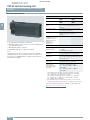
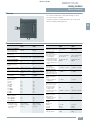
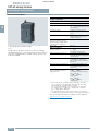
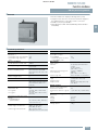
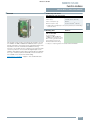
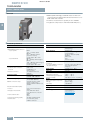
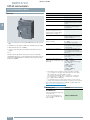
■ Overview
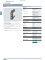
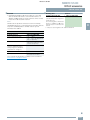
SIMATIC S7-200
• The micro PLC that offers maximum automation at minimum
cost.
• Extremely simple installation, programming and operation.
• Large-scale integration, space-saving, powerful.
• Can be used both for simple controls and for complex
automation tasks.
• All CPUs can be used in stand-alone mode, in networks and
within distributed structures.
• Suitable for applications where programmable controllers
would not have been economically viable in the past.
• With outstanding real-time performance and powerful
communication options (PPI, PROFIBUS DP, AS-Interface)
3
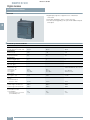
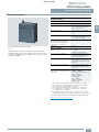
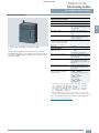
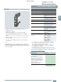
SIPLUS S7-200
• The PLC for use under extremely harsh ambient conditions
• With extended temperature range from -25 °C to +70 °C
• Use in environments with pollutant gases (corrosive gas
atmospheres)
• Condensation and enhanced mechanical stress permissible
• With the proven PLC technology of the S7-200
• Easy handling, programming, maintenance and service
• Ideal for use in automobile construction, environmental
technology, mining, chemical plants, conveying technology,
food & beverages industry etc.
• The substitute for expensive special solutions
You will find more information at:
www.siemens.com/siplus-extreme
For brochures serving as selection guides for SIMATIC products
refer to:
www.siemens.com/simatic/printmaterial
3/2
Siemens ST 70 · 2011
© Siemens AG 2011
SIMATIC S7-200
Introduction
S7-200
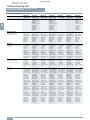
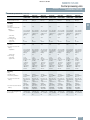
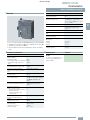
■ Technical specifications
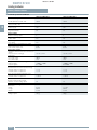
General technical specifications SIMATIC S7-200
General technical specifications SIMATIC S7-200
Degree of protection
IP20 according to IEC 529
Conformal coating
Ambient temperature
• Operation
(95 % relative humidity)
- With horizontal mounting
- With vertical mounting
• Transport and storage
- with 95 % relative humidity
Coating of the printed circuit
boards and the electronic components
Ambient temperature range
-25 ... +70 °C
0 … 55°C
0 … 45 °C
-40 … +70 °C
25 … 55 °C
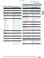
Technical data
The technical data of the
standard product applies except
for the ambient conditions.
Isolation
• 5/24 V DC circuits
• 115/230 V AC circuits to ground
• 115/230 V AC circuits to
115/230 V AC circuits
• 230 V AC circuits to
5/24 V DC circuits
• 115 V AC circuits to
5/24 V DC circuits
Electromagnetic compatibility
• Noise immunity according to
EN 50082-2
• Emitted interference according to
EN 50081-1 and
EN 50081-2
Mechanical rating
• Vibrations, tested according to/
tested with
• Shock, tested according to/tested
with
Test voltage 500 V AC
Test voltage 1500 V AC
Test voltage 1500 V AC
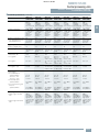
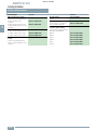
Ambient conditions:
• Relative humidity
• Biologically active substances
• Chemically active substances
Test voltage 1500 V AC
Test voltage 1500 V AC
Requirements of EMC law
Tested according to:
IEC 801-2, IEC 801-3, IEC 801-4,
EN 50141, EN 50204, IEC 801-5,
VDE 0160
Tested according to
EN 55011, Class A,
Group 1 and
EN 55011, Class B,
Group 1
IEC 68, Part 2-6:
10 to 57 Hz;
constant amplitude
0.3 mm;
58 … 150 Hz;
constant acceleration 1 g
(mounted on DIN rail) or
2 g (mounted in control cabinet);
type of vibration:
frequency cycles with a rate of
change of 1 octave/minute;
vibration duration:
10 frequency cycles per axis in
each direction of the 3 mutually
perpendicular axes
IEC 68, Part 2-27/half-sine:
shock strength 15 g (peak value),
duration 11 ms, 6 shocks on each
of the 3 mutually perpendicular
axes
• Mechanically active substances
5 ... 100%, condensation allowed
Conformity with EN 60721-3-3,
Class 3B2 mold and fungal
spores (except fauna)
Conformity with EN 60721-3-3,
Class 3C4 incl. salt mist and
ISA–S71.04 severity level G1; G2;
G3; GX 1) 2)
Conformity with EN 60721-3-3,
Class 3S4 including conductive
sand, dust 2)
Air pressure (depending on the
highest positive temperature range
specified)
1080 ... 795 hPa
(-1000 ... +2000 m)
see ambient temperature range
795 ... 658 hPa
(+2000 ... + 3500 m)
Derating 10K
658 ... 540 hPa
(+3500 ... +5000 m)
derating 20 K
Conforms with standard for
electronic equipment used on
rolling stock
(EN 50155, temperature T1,
category 1)
Yes 3)
1) ISA-S71.04 severity level GX: Long-term load: SO2 < 4.8 ppm;
H2S < 9.9 ppm; Cl < 0.2 ppm; HCl < 0.66 ppm; HF < 0.12 ppm;
NH < 49 ppm; O3 < 0.1 ppm; NOX < 5.2 ppm
Limit value (max. 30 min/d): SO2 < 17.8 ppm; H2S < 49.7 ppm;
Cl < 1.0 ppm; HCl < 3.3 ppm; HF < 2.4 ppm; NH < 247 ppm;
O3 < 1.0 ppm; NOX < 10.4 ppm
2) The supplied plug covers must remain in place over the unused
interface when operated in atmospheres containing corrosive gases!
3) Does not apply to:
6AG1 214-2AD23-2XB0
6AG1 214-2BD23-2XB0
6AG1 232-0HB22-2XB0
6AG1 235-0KD22-2XB0
6AG1 231-7PB22-2XA0
6AG1 901-3CB30-2XA0
Siemens ST 70 · 2011
3/3
3
© Siemens AG 2011
SIMATIC S7-200
Central processing units
CPU 221, CPU 222, CPU 224, CPU 224 XP,
CPU 224 XPsi, CPU 226
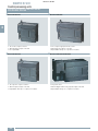
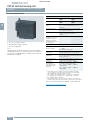
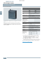
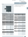
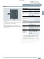
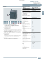
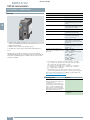
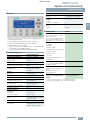
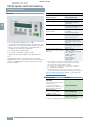
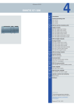
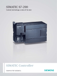
■ Overview CPU 221
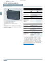
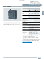
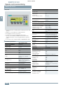
■ Overview CPU 224
3
• The smart compact solution
• With 10 inputs/outputs on board
• Not expandable
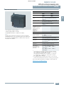
■ Overview CPU 222
• The superior compact solution
• With 14 inputs/outputs on board
• Expandable with up to 2 expansion modules
3/4
Siemens ST 70 · 2011
• The compact high-performance CPU
• With 24 inputs/outputs on board
• Expandable with up to 7 expansion modules
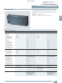
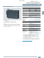
■ Overview CPU 224 XP/224 XPsi
• The power CPU
• With 24 digital and 3 analog inputs/outputs onboard
• Expandable with up to 7 expansion modules
© Siemens AG 2011
SIMATIC S7-200
Central processing units
CPU 221, CPU 222, CPU 224, CPU 224 XP,
CPU 224 XPsi, CPU 226
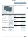
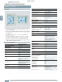
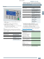
■ Overview CPU 226
• The high-performance package for complex technical tasks
• With additional PPI port for more flexibility and communication
options
• With 40 inputs/outputs on board
• Expansion capability for max. 7 expansion racks
3
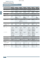
■ Technical specifications
6ES7 211-0AA23-0XB0
Supply voltages
Rated value
• 24 V DC
• permissible range,
lower limit (DC)
• permissible range,
upper limit (DC)
• 120 V AC
• 230 V AC
• permissible range,
lower limit (AC)
• permissible range,
upper limit (AC)
• permissible frequency
range, lower limit
• permissible frequency
range, upper limit
Load voltage L+
• Rated value (DC)
• permissible range,
lower limit (DC)
• permissible range,
upper limit (DC)
6ES7 212-1AB23-0XB0
Yes
20.4 V
Yes
20.4 V
28.8 V
28.8 V
6ES7 212-1BB23-0XB0
Yes
Yes
85 V
Yes
Yes
85 V
264 V
264 V
47 Hz
47 Hz
63 Hz
63 Hz
24 V
20.4 V
24 V
5V
24 V
20.4 V
24 V
5V
28.8 V
30 V
28.8 V
30 V
Load voltage L1
• Rated value (AC)
• permissible range,
lower limit (AC)
• permissible range,
upper limit (AC)
• permissible frequency
range, lower limit
• permissible frequency
range, upper limit
Current consumption
Inrush current, max.
10 A; at 28.8 V
from supply voltage L+, max.
450 mA; 80 to 450 mA
from supply voltage L1, max.
6ES7 211-0BA23-0XB0
100 V; 100 to 230 V AC
5V
100 V; 100 to 230 V AC
5V
250 V
250 V
47 Hz
47 Hz
63 Hz
63 Hz
20 A; at 264 V
10 A; at 28.8 V
20 A; at 264 V
500 mA; 85 to 500 mA,
output current for
expansion modules
(DC 5 V) 340 mA
120 mA; 15 to 60 mA
(240 V); 30 to 120 mA
(120 V); output current for
expansion modules
(5 V DC) 340 mA
140 mA; 20 to 70 mA
(240 V); 40 to 140 mA
(120 V); output current for
expansion modules
(5 V DC) 340 mA
Siemens ST 70 · 2011
3/5
© Siemens AG 2011
SIMATIC S7-200
Central processing units
CPU 221, CPU 222, CPU 224, CPU 224 XP,
CPU 224 XPsi, CPU 226
■ Technical specifications (continued)
Backup battery
Battery operation
• Backup time, max.
3
Memory
Number of memory modules
(optional)
Data and program memory
• Data memory, max.
• Program memory, max.
Backup
• present
CPU processing times
for bit operations, max.
Counters, timers and their
retentivity
S7 counter
• Number
• of which retentive with
battery
- adjustable
- lower limit
- upper limit
• Counting range
- lower limit
- upper limit
S7 times
• Number
• of which retentive with
battery
- adjustable
- upper limit
• Time range
- lower limit
- upper limit
3/6
6ES7 211-0AA23-0XB0
6ES7 211-0BA23-0XB0
6ES7 212-1AB23-0XB0
6ES7 212-1BB23-0XB0
50 h; (min. 8 h at 40 °C);
200 days (typ.) with
optional battery module
50 h; (min. 8 h at 40 °C);
200 days (typ.) with
optional battery module
50 h; (min. 8 h at 40 °C);
200 days (typ.) with
optional battery module
50 h; (min. 8 h at 40 °C);
200 days (typ.) with
optional battery module
1; pluggable memory
module, content identical
with integral EEPROM; can
additionally store recipes,
data logs and other files
1; pluggable memory
module, content identical
with integral EEPROM; can
additionally store recipes,
data logs and other files
1; pluggable memory
module, content identical
with integral EEPROM; can
additionally store recipes,
data logs and other files
1; pluggable memory
module, content identical
with integral EEPROM; can
additionally store recipes,
data logs and other files
2 Kibyte
4 Kibyte
2 Kibyte
4 Kibyte
2 Kibyte
4 Kibyte
2 Kibyte
4 Kibyte
Yes; Program: Entire
program maintenance-free
on integral EEPROM,
programmable via CPU;
data: Entire DB 1 loaded
from PG/PC maintenancefree on integral EEPROM,
current values of DB 1 in
RAM, retentive memory
bits, timers, counters, etc.
maintenance-free via highperformance capacitor;
optional battery for longterm buffering
0.22 μs
0.22 μs
0.22 μs
0.22 μs
256
256
256
256
Yes; via high-performance
capacitor or battery
1
256
Yes; via high-performance
capacitor or battery
1
256
Yes; via high-performance
capacitor or battery
1
256
Yes; via high-performance
capacitor or battery
1
256
0
32 767
0
32 767
0
32 767
0
32 767
256
256
256
256
Yes; via high-performance
capacitor or battery
64
Yes; via high-performance
capacitor or battery
64
Yes; via high-performance
capacitor or battery
64
Yes; via high-performance
capacitor or battery
64
1 ms
54 min; 4 timers: 1 ms to
30 s; 16 timers: 10 ms to
5 min; 236 timers: 100 ms
to 54 min
1 ms
54 min; 4 timers: 1 ms to
30 s; 16 timers: 10 ms to
5 min; 236 timers: 100 ms
to 54 min
1 ms
54 min; 4 timers: 1 ms to
30 s; 16 timers: 10 ms to
5 min; 236 timers: 100 ms
to 54 min
1 ms
54 min; 4 timers: 1 ms to
30 s; 16 timers: 10 ms to
5 min; 236 timers: 100 ms
to 54 min
Siemens ST 70 · 2011
© Siemens AG 2011
SIMATIC S7-200
Central processing units
CPU 221, CPU 222, CPU 224, CPU 224 XP,
CPU 224 XPsi, CPU 226
■ Technical specifications (continued)
6ES7 211-0AA23-0XB0
6ES7 211-0BA23-0XB0
6ES7 212-1AB23-0XB0
6ES7 212-1BB23-0XB0
• of which retentive without
battery
32 byte
Yes; M 0.0 to M 31.7
0 to 255, via highperformance capacitor or
battery, adjustable
0 to 112 in EEPROM,
adjustable
32 byte
Yes; M 0.0 to M 31.7
0 to 255, via highperformance capacitor or
battery, adjustable
0 to 112 in EEPROM,
adjustable
32 byte
Yes; M 0.0 to M 31.7
0 to 255, via highperformance capacitor or
battery, adjustable
0 to 112 in EEPROM,
adjustable
32 byte
Yes; M 0.0 to M 31.7
0 to 255, via highperformance capacitor or
battery, adjustable
0 to 112 in EEPROM,
adjustable
Hardware configuration
Connectable programming
devices/PCs
SIMATIC PG/PC,
standard PC
SIMATIC PG/PC,
standard PC
SIMATIC PG/PC,
standard PC
SIMATIC PG/PC,
tandard PC
2; Only expansion modules
of the S7-22x series can be
used. Due to the limited
output current, the use of
expansion modules may be
limited.
2; Only expansion modules
of the S7-22x series can be
used. Due to the limited
output current, the use of
expansion modules may be
limited.
10; max. 8 inputs and
2 outputs (EM) or max.
0 inputs and 4 outputs (EM)
78; max. 40 inputs and
38 outputs (CPU + EM)
62; AS-Interface A/B slaves
(CP 243-2)
10; max. 8 inputs and
2 outputs (EM) or max.
0 inputs and 4 outputs (EM)
78; max. 40 inputs and
38 outputs (CPU + EM)
62; AS-Interface A/B slaves
(CP 243-2)
No
No
Data areas and their
retentivity
Flag
• Number, max.
• Retentivity available
• of which retentive with
battery
Expansion devices, max.
Extension of distributed I/O
• Analog inputs/outputs, max.
• Digital inputs/outputs, max.
• AS-Interface inputs/outputs
max.
Connection method
Plug-in I/O terminals
No
1st interface
Type of interface
Integrated RS 485 interface Integrated RS 485 interface Integrated RS 485 interface Integrated RS 485 interface
Physics
RS 485
RS 485
RS 485
RS 485
Yes; as MPI slave for data
exchange with MPI masters
(S7-300/S7-400 CPUs,
OPs, TDs, Push Button
Panels); S7-200-internal
CPU/CPU communications
is possible in the MPI
network with restrictions;
transmission rates: 19.2 /
187.5 kbit/s
Yes; with PPI protocol for
programming functions,
HMI functions (TD 200,
OP), S7-200-internal CPU/
CPU communications;
transmission rates 9.6 /
19.2 / 187.5 kbit/s
Functionality
• MPI
• PPI
No
Siemens ST 70 · 2011
3/7
3
© Siemens AG 2011
SIMATIC S7-200
Central processing units
CPU 221, CPU 222, CPU 224, CPU 224 XP,
CPU 224 XPsi, CPU 226
■ Technical specifications (continued)
6ES7 211-0AA23-0XB0
• Serial data exchange
3
6ES7 211-0BA23-0XB0
6ES7 212-1AB23-0XB0
6ES7 212-1BB23-0XB0
Yes; as freely programmable Yes; as freely programmable Yes; as freely programmable Yes; as freely programmable
interface with interrupt facility interface with interrupt facility interface with interrupt facility interface with interrupt facility
for serial data exchange with for serial data exchange with for serial data exchange with for serial data exchange with
third-party devices with ASCII third-party devices with ASCII third-party devices with ASCII third-party devices with ASCII
protocol transfer rates: 1.2 / protocol transfer rates: 1.2 / protocol transfer rates: 1.2 / protocol transfer rates: 1.2 /
2.4 / 4.8 / 9.6 / 19.2 / 38.4 / 2.4 / 4.8 / 9.6 / 19.2 / 38.4 / 2.4 / 4.8 / 9.6 / 19.2 / 38.4 / 2.4 / 4.8 / 9.6 / 19.2 / 38.4 /
57.6 / 115.2 kbit/s; the PC / 57.6 / 115.2 kbit/s; the PC / 57.6 / 115.2 kbit/s; the PC / 57.6 / 115.2 kbit/s; the PC /
PPI cable can also be used PPI cable can also be used PPI cable can also be used PPI cable can also be used
as RS232 / RS485 converter as RS232 / RS485 converter as RS232 / RS485 converter as RS232 / RS485 converter
MPI
• Transmission rate, max.
• Transmission rate, min.
187.5 kbit/s
19.2 kbit/s
187.5 kbit/s
19.2 kbit/s
187.5 kbit/s
19.2 kbit/s
187.5 kbit/s
19.2 kbit/s
Programming
Programming language
• LAD
• FBD
• STL
Yes
Yes
Yes
Yes
Yes
Yes
Yes
Yes
Yes
Yes
Yes
Yes
Command set
Bit logic instructions,
compare instructions, timer
instructions, counter
instructions, clock instructions, transmissions
instructions, table instructions, logic instructions,
shift and rotate instructions,
conversion instructions,
program control instructions, interrupt and communications instructions, logic
stack instructions, integer
maths, floating-point math
instructions, numerical
functions
Program processing
free cycle (OB 1), interruptcontroller, time-controlled
(1 to 255 ms)
free cycle (OB 1), interruptcontroller, time-controlled
(1 to 255 ms)
free cycle (OB 1), interruptcontroller, time-controlled
(1 to 255 ms)
free cycle (OB 1), interruptcontroller, time-controlled
(1 to 255 ms)
Program organization
1 OB, 1 DB, 1 SDB
subroutines with/without
parameter transfer
1 OB, 1 DB, 1 SDB
subroutines with/without
parameter transfer
1 OB, 1 DB, 1 SDB
subroutines with/without
parameter transfer
1 OB, 1 DB, 1 SDB
subroutines with/without
parameter transfer
Number of subroutines, max.
• User program protection/
password protection
64
Yes; 3-stage password
protection
64
Yes; 3-stage password
protection
64
Yes; 3-stage password
protection
64
Yes; 3-stage password
protection
Digital inputs
Number of digital inputs
6; Integrated
6; Integrated
8
8
m/p-reading
Yes; optionally, per group
Yes; optionally, per group
Yes; optionally, per group
Yes; optionally, per group
Input voltage
• Rated value, DC
• for signal "0"
• for signal "1"
24 V
0 to 5 V
min. 15 V
24 V
0 to 5 V
min. 15 V
24 V
0 to 5 V
min. 15 V
24 V
0 to 5 V
min. 15 V
Input current
• for signal "1", typ.
2.5 mA
2.5 mA
2.5 mA
2.5 mA
Yes; all
0.2 ms
12.8 ms
Yes; all
0.2 ms
12.8 ms
Yes; all
0.2 ms
12.8 ms
Yes; all
0.2 ms
12.8 ms
Yes; I 0.0 to I 0.3
Yes; I 0.0 to I 0.3
Yes; I 0.0 to I 0.3
Yes; I 0.0 to I 0.3
Yes; (E0.0 to E0.5) 30 kHz
Yes; (E0.0 to E0.5) 30 kHz
Yes; (E0.0 to E0.5) 30 kHz
Yes; (E0.0 to E0.5) 30 kHz
Input delay (for rated value of
input voltage)
• for standard inputs
- parameterizable
- at "0" to "1", min.
- at "0" to "1", max.
• for interrupt inputs
- parameterizable
• for counter/technological
functions
- parameterizable
3/8
Siemens ST 70 · 2011
© Siemens AG 2011
SIMATIC S7-200
Central processing units
CPU 221, CPU 222, CPU 224, CPU 224 XP,
CPU 224 XPsi, CPU 226
■ Technical specifications (continued)
6ES7 211-0AA23-0XB0
6ES7 211-0BA23-0XB0
6ES7 212-1AB23-0XB0
6ES7 212-1BB23-0XB0
• Cable length unshielded,
max.
500 m; Standard input:
500 m, high-speed
counters: 50 m
300 m; not for high-speed
signals
500 m; Standard input:
500 m, high-speed
counters: 50 m
300 m; not for high-speed
signals
500 m; Standard input:
500 m, high-speed
counters: 50 m
300 m; not for high-speed
signals
500 m; Standard input:
500 m, high-speed
counters: 50 m
300 m; not for high-speed
signals
Digital outputs
Number of digital outputs
4; Transistor
4; Relay
6; Transistor
6; Relay
Short-circuit protection
No; to be provided externally
No; to be provided externally
No; to be provided externally
No; to be provided externally
Limitation of inductive
shutdown voltage to
1W
Cable length
• Cable length, shielded,
max.
1W
Switching capacity of the
outputs
• with resistive load, max.
• on lamp load, max.
0.75 A
5W
2A
30 W DC; 200 W AC
0.75 A
5W
2A
30 W DC; 200 W AC
Output voltage
• for signal "1", min.
20 V DC
L+/L1
20 V DC
L+/L1
750 mA
0.1 mA
2A
0 mA
750 mA
10 μA
2A
0 mA
15 μs; of the standard
outputs, max. (Q 0.2 to
Q 0.3) 15 μs; of the pulse
outputs, max. (Q 0.0 to
Q 0.1) 2 μs
130 μs; of the standard
outputs, max. (Q 0.2 to
Q 0.3) 100 μs; of the pulse
outputs, max. (Q 0.0 to
Q 0.1) 10 μs
10 ms; all outputs
15 μs; of the standard
outputs, max. (Q 0.2 to
Q 0.5) 15 μs; of the pulse
outputs, max. (Q 0.0 to
Q 0.1) 2 μs
130 μs; of the standard
outputs, max. (Q 0.2 to
Q 0.5) 100 μs; of the pulse
outputs, max. (Q 0.0 to
Q 0.1) 10 μs
10 ms; all outputs
Yes
No
Output current
• for signal "1" rated value
• for signal "0" residual
current, max.
Output delay with resistive
load
• 0 to "1", max.
• 1 to "0", max.
Parallel switching of 2 outputs
• for increased power
Yes
Switching frequency
• of the pulse outputs, with
resistive load, max.
Aggregate current of outputs
(per group)
• horizontal installation
- up to 55 °C, max.
• up to 40 °C, max.
Cable length
• Cable length, shielded,
max.
• Cable length unshielded,
max.
Encoder supply
24 V encoder supply
• 24 V
• Short-circuit protection
• Output current, max.
No
20 kHz; Q 0.0 to Q 0.1
10 ms; all outputs
20 kHz; Q 0.0 to Q 0.1
3A
3A
6A
6A
4.5 A
4.5 A
6A
6A
500 m
500 m
500 m
500 m
150 m
150 m
150 m
150 m
Relay outputs
Number of operating cycles
Analog inputs
Number of analog potentiometers
10 ms; all outputs
10 000 000; mechanically
10 million, at rated load
voltage 100,000
10 000 000; mechanically
10 million, at rated load
voltage 100,000
1; Analog potentiometer;
resolution 8 bit
1; Analog potentiometer;
resolution 8 bit
1; Analog potentiometer;
resolution 8 bit
1; Analog potentiometer;
resolution 8 bit
Yes; permissible range:
15.4 to 28.8 V
Yes; electronic at 600 mA
180 mA
Yes; permissible range:
20.4 bis 28.8 V
Yes; electronic at 600 mA
180 mA
Yes; permissible range:
15.4 to 28.8 V
Yes; electronic at 600 mA
180 mA
Yes; permissible range:
20.4 bis 28.8 V
Yes; electronic at 600 mA
180 mA
Siemens ST 70 · 2011
3/9
3
© Siemens AG 2011
SIMATIC S7-200
Central processing units
CPU 221, CPU 222, CPU 224, CPU 224 XP,
CPU 224 XPsi, CPU 226
■ Technical specifications (continued)
3
6ES7 211-0AA23-0XB0
6ES7 211-0BA23-0XB0
6ES7 212-1AB23-0XB0
6ES7 212-1BB23-0XB0
Yes
1 mA
Yes
1 mA
Yes
1 mA
Yes
1 mA
4; High-speed counters
(30 kHz each), 32 bit (incl.
sign), can be used as up/
down counters or for
connecting 2 incremental
encoders with 2 pulse
trains offset by 90° (max.
20 kHz (A/B counters));
parameterizable enable
and reset input; interrupt
facilities (incl. call of
subroutine with any
content) when the setpoint
is reached; reversal in
counting direction, etc.
Counter frequency (counter)
max.
30 kHz
30 kHz
30 kHz
30 kHz
Number of alarm inputs
4; 4 rising edges and/or
4 falling edges
4; 4 rising edges and/or
4 falling edges
4; 4 rising edges and/or
4 falling edges
4; 4 rising edges and/or
4 falling edges
Number of pulse outputs
2; high-speed outputs,
20 kHz, with interrupt
option; pulse-width and
frequency modulation
option
2; high-speed outputs,
20 kHz, with interrupt
option; pulse-width and
frequency modulation
option
Limit frequency (pulse)
20 kHz
20 kHz
Encoder
Connectable encoders
• 2-wire BEROS
- permissible quiescent
current (2-wire BEROS),
max.
Integrated Functions
Number of counters
Galvanic isolation
Galvanic isolation digital
inputs
• between the channels
• between the channels,
in groups of
Yes
2 and 4
Yes
2 and 4
Yes
4
Yes
4
Yes; Optocoupler
4
Yes; Relay
1 and 3
Yes; Optocoupler
6
Yes; Relay
3
500 V DC between 24 V DC
and 5 V DC
500 V DC between 24 V DC
and 5 V DC; 1500 V AC
between 24 V DC and
230 V AC
500 V DC between 24 V DC
and 5 V DC
500 V DC between 24 V DC
and 5 V DC; 1500 V AC
between 24 V DC and
230 V AC
For further ambient conditions, see "Automation
System S7200, System
Manual"
For further ambient conditions, see "Automation
System S7-200, System
Manual"
For further ambient conditions, see "Automation
System S7-200, System
Manual"
For further ambient conditions, see "Automation
System S7-200, System
Manual"
Operating temperature
• vertical installation, min.
• vertical installation, max.
• horizontal installation, min.
• horizontal installation, max.
0 °C
45 °C
0 °C
55 °C
0 °C
45 °C
0 °C
55 °C
0 °C
45 °C
0 °C
55 °C
0 °C
45 °C
0 °C
55 °C
Air pressure
• permissible range, min.
• permissible range, max.
860 hPa
1 080 hPa
860 hPa
1 080 hPa
860 hPa
1 080 hPa
860 hPa
1 080 hPa
5%
95 %; RH class 2 in accordance with
IEC 1131-2
5%
95 %; RH class 2
in accordance with
IEC 1131-2
5%
95 %; RH class 2
in accordance with
IEC 1131-2
5%
95 %; RH class 2
in accordance with
IEC 1131-2
Galvanic isolation digital
outputs
• between the channels
• between the channels,
in groups of
Permissible potential
difference
between different circuits
Environmental requirements
Ambient conditions
Relative humidity
• Operation, min.
• Operation, max.
3/10
Siemens ST 70 · 2011
© Siemens AG 2011
SIMATIC S7-200
Central processing units
CPU 221, CPU 222, CPU 224, CPU 224 XP,
CPU 224 XPsi, CPU 226
■ Technical specifications (continued)
6ES7 211-0AA23-0XB0
6ES7 211-0BA23-0XB0
6ES7 212-1AB23-0XB0
6ES7 212-1BB23-0XB0
Degree of protection
IP20
Yes
Yes
Yes
Yes
Dimensions and weight
Dimensions
• Width
• Height
• Depth
90 mm
80 mm
62 mm
90 mm
80 mm
62 mm
90 mm
80 mm
62 mm
90 mm
80 mm
62 mm
Weight
• Weight, approx.
270 g
310 g
270 g
310 g
6ES7 2141AD23-0XB0
Supply voltages
Rated value
• 24 V DC
• permissible range,
lower limit (DC)
• permissible range,
upper limit (DC)
• 120 V AC
• 230 V AC
• permissible range,
lower limit (AC)
• permissible range,
upper limit (AC)
• permissible frequency
range, lower limit
• permissible frequency
range, upper limit
Load voltage L+
• Rated value (DC)
• permissible range,
lower limit (DC)
• permissible range,
upper limit (DC)
6ES7 2142BD23-0XB0
6ES7 2142AS23-0XB0
6ES7 2162AD23-0XB0
Yes
20.4 V
Yes
20.4 V
Yes
20.4 V
28.8 V
28.8 V
28.8 V
28.8 V
6ES7 2162BD23-0XB0
Yes
Yes
85 V
Yes
Yes
85 V
Yes
Yes
85 V
264 V
264 V
264 V
47 Hz
47 Hz
47 Hz
63 Hz
63 Hz
63 Hz
24 V
20.4 V
24 V
5V
24 V
20.4 V
24 V
5V
24 V
20.4 V
24 V
20.4 V
24 V
5V
28.8 V
30 V
28.8 V
30 V
28.8 V
28.8 V
30 V
• permissible range,
lower limit (AC)
• permissible range,
upper limit (AC)
• permissible frequency
range, lower limit
• permissible frequency
range, upper limit
from supply voltage L+, max.
6ES7 2142AD23-0XB0
Yes
20.4 V
Load voltage L1
• Rated value (AC)
Current consumption
Inrush current, max.
6ES7 2141BD23-0XB0
3
12 A; at 28.8 V
700 mA; 110
to 700 mA,
output current
for expansion
modules
(5 V DC)
660 mA
100 V; 100 to
230 V AC
5V
100 V; 100 to
230 V AC
5V
100 V; 100 to
230 V AC
5V
250 V
250 V
250 V
47 Hz
47 Hz
47 Hz
63 Hz
63 Hz
63 Hz
20 A; at 264 V
12 A; at 28.8 V
900 mA; 120
to 900 mA,
output current
for expansion
modules
(5 V DC)
660 mA
20 A; at 264 V
12 A; at 28.8 V
10 A; at 28.8 V
900 mA; 120
to 900 mA,
output current
for expansion
modules
(5 V DC)
660 mA
1 050 mA; 150
to 1050 mA
output current
for expansion
modules
(D5 V DC)
1000 mA
20 A; at 264 V
Siemens ST 70 · 2011
3/11
© Siemens AG 2011
SIMATIC S7-200
Central processing units
CPU 221, CPU 222, CPU 224, CPU 224 XP,
CPU 224 XPsi, CPU 226
■ Technical specifications (continued)
6ES7 2141AD23-0XB0
from supply voltage L1, max.
Memory
Number of memory modules
(optional)
Data and program memory
• Data memory, max.
• Program memory, max.
Backup
• present
3/12
6ES7 2142AD23-0XB0
200 mA; 30 to
100 mA
(240 V); 60 to
200 mA
(120 V); output
current for
expansion
modules
(5 V DC)
600 mA
3
Backup battery
Battery operation
• Backup time, max.
6ES7 2141BD23-0XB0
6ES7 2142BD23-0XB0
6ES7 2142AS23-0XB0
6ES7 2162AD23-0XB0
220 mA; 35 to
100 mA
(240 V); 70 to
220 mA
(120 V); output
current for
expansion
modules
(5 V DC)
600 mA
6ES7 2162BD23-0XB0
320 mA; 40 to
160 mA
(240 V); 80 to
320 mA
(120 V); output
current for
expansion
modules
(5 V DC)
1000 mA
100 h; (min.
70 h at 40 °C);
200 days
(typ.) with
optional
battery
module
100 h; (min.
70 h at 40 °C);
200 days
(typ.) with
optional
battery
module
100 h; (min.
70 h at 40 °C);
200 days
(typ.) with
optional
battery
module
100 h; (min.
70 h at 40 °C);
200 days
(typ.) with
optional
battery
module
100 h; (min.
70 h at 40 °C);
200 days
(typ.) with
optional
battery
module
100 h; (min.
70 h at 40 °C);
200 days
(typ.) with
optional
battery
module
100 h; (min.
70 h at 40 °C);
200 days
(typ.) with
optional
battery
module
1; pluggable
memory
module,
content
identical with
integral
EEPROM; can
additionally
store recipes,
data logs and
other files
1; pluggable
memory
module,
content
identical with
integral
EEPROM; can
additionally
store recipes,
data logs and
other files
1; pluggable
memory
module,
content
identical with
integral
EEPROM; can
additionally
store recipes,
data logs and
other files
1; pluggable
memory
module,
content
identical with
integral
EEPROM; can
additionally
store recipes,
data logs and
other files
1; pluggable
memory
module,
content
identical with
integral
EEPROM; can
additionally
store recipes,
data logs and
other files
1; pluggable
memory
module,
content
identical with
integral
EEPROM; can
additionally
store recipes,
data logs and
other files
1; pluggable
memory
module,
content
identical with
integral
EEPROM; can
additionally
store recipes,
data logs and
other files
8 Kibyte
12 Kibyte;
8 KB with
active run-time
edit
8 Kibyte
12 Kibyte;
8 KB with
active run-time
edit
10 Kibyte
16 Kibyte;
12 KB with
active run-time
edit
10 Kibyte
16 Kibyte;
12 KB with
active run-time
edit
10 Kibyte
16 Kibyte;
12 KB with
active run-time
edit
10 Kibyte
24 Kibyte;
16 KB with
active run-time
edit
10 Kibyte
24 Kibyte;
16 KB with
active run-time
edit
Yes; Program:
Entire program
maintenancefree on integral
EEPROM,
programmable via
CPU; data:
Entire DB 1
loaded from
PG/PC maintenance-free on
integral
EEPROM,
current values
of DB 1 in
RAM, retentive
memory bits,
timers,
counters, etc.
maintenancefree via highperformance
capacitor;
optional
battery for
long-term
buffering
Siemens ST 70 · 2011
© Siemens AG 2011
SIMATIC S7-200
Central processing units
CPU 221, CPU 222, CPU 224, CPU 224 XP,
CPU 224 XPsi, CPU 226
■ Technical specifications (continued)
CPU processing times
for bit operations, max.
Counters, timers and their
retentivity
S7 counter
• Number
• of which retentive with
battery
- adjustable
- lower limit
- upper limit
• Counting range
- lower limit
- upper limit
S7 times
• Number
• of which retentive with
battery
- adjustable
- upper limit
• Time range
- lower limit
- upper limit
Data areas and their
retentivity
Flag
• Number, max.
• Retentivity available
• of which retentive with
battery
• of which retentive without
battery
Hardware configuration
Connectable programming
devices/PCs
6ES7 2141AD23-0XB0
6ES7 2141BD23-0XB0
6ES7 2142AD23-0XB0
6ES7 2142BD23-0XB0
6ES7 2142AS23-0XB0
6ES7 2162AD23-0XB0
6ES7 2162BD23-0XB0
0.22 μs
0.22 μs
0.22 μs
0.22 μs
0.22 μs
0.22 μs
0.22 μs
256
256
256
256
256
256
256
Yes; via highperformance
capacitor or
battery
1
256
Yes; via highperformance
capacitor or
battery
1
256
Yes; via highperformance
capacitor or
battery
1
256
Yes; via highperformance
capacitor or
battery
1
256
Yes; via highperformance
capacitor or
battery
1
256
Yes; via highperformance
capacitor or
battery
1
256
Yes; via highperformance
capacitor or
battery
1
256
0
32 767
0
32 767
0
32 767
0
32 767
0
32 767
0
32 767
0
32 767
256
256
256
256
256
256
256
Yes; via highperformance
capacitor or
battery
64
Yes; via highperformance
capacitor or
battery
64
Yes; via highperformance
capacitor or
battery
64
Yes; via highperformance
capacitor or
battery
64
Yes; via highperformance
capacitor or
battery
64
Yes; via highperformance
capacitor or
battery
64
Yes; via highperformance
capacitor or
battery
64
1 ms
54 min;
4 timers: 1 ms
to 30 s;
16 timers:
10 ms to
5 min;
236 timers:
100 ms to
54 min
1 ms
54 min;
4 timers: 1 ms
to 30 s;
16 timers:
10 ms to
5 min;
236 timers:
100 ms to
54 min
1 ms
54 min;
4 timers: 1 ms
to 30 s;
16 timers:
10 ms to
5 min;
236 timers:
100 ms to
54 min
1 ms
54 min;
4 timers: 1 ms
to 30 s;
16 timers:
10 ms to
5 min;
236 timers:
100 ms to
54 min
1 ms
54 min;
4 timers: 1 ms
to 30 s;
16 timers:
10 ms to
5 min;
236 timers:
100 ms to
54 min
1 ms
54 min;
4 timers: 1 ms
to 30 s;
16 timers:
10 ms to
5 min;
236 timers:
100 ms to
54 min
1 ms
54 min;
4 timers: 1 ms
to 30 s;
16 timers:
10 ms to
5 min;
236 timers:
100 ms to
54 min
32 byte
Yes; M 0.0 to
M 31.7
0 to 255, via
high-performance
capacitor or
battery,
adjustable
0 to 112 in
EEPROM,
adjustable
32 byte
Yes; M 0.0 to
M 31.7
0 to 255, via
high-performance
capacitor or
battery,
adjustable
0 to 112 in
EEPROM,
adjustable
32 byte
Yes; M 0.0 to
M 31.7
0 to 255, via
high-performance
capacitor or
battery,
adjustable
0 to 112 in
EEPROM,
adjustable
32 byte
Yes; M 0.0 to
M 31.7
0 to 255, via
high-performance
capacitor or
battery,
adjustable
0 to 112 in
EEPROM,
adjustable
32 byte
Yes; M 0.0 to
M 31.7
0 to 255, via
high-performance
capacitor or
battery,
adjustable
0 to 112 in
EEPROM,
adjustable
32 byte
Yes; M 0.0 to
M 31.7
0 to 255, via
high-performance
capacitor or
battery,
adjustable
0 to 112 in
EEPROM,
adjustable
32 byte
Yes; M 0.0 to
M 31.7
0 to 255, via
high-performance
capacitor or
battery,
adjustable
0 to 112 in
EEPROM,
adjustable
SIMATIC PG/
PC, standard
PC
SIMATIC PG/
PC, standard
PC
SIMATIC PG/
PC, standard
PC
SIMATIC PG/
PC, standard
PC
SIMATIC PG/
PC, standard
PC
SIMATIC PG/
PC, standard
PC
SIMATIC PG/
PC, standard
PC
Siemens ST 70 · 2011
3
3/13
© Siemens AG 2011
SIMATIC S7-200
Central processing units
CPU 221, CPU 222, CPU 224, CPU 224 XP,
CPU 224 XPsi, CPU 226
■ Technical specifications (continued)
6ES7 2141AD23-0XB0
6ES7 2141BD23-0XB0
6ES7 2142AD23-0XB0
6ES7 2142BD23-0XB0
6ES7 2142AS23-0XB0
6ES7 2162AD23-0XB0
6ES7 2162BD23-0XB0
7; Only
expansion
modules of the
S7-22x series
can be used.
Due to the
limited output
current, the
use of
expansion
modules may
be limited.
7; Only
expansion
modules of the
S7-22x series
can be used.
Due to the
limited output
current, the
use of
expansion
modules may
be limited.
7; Only
expansion
modules of the
S7-22x series
can be used.
Due to the
limited output
current, the
use of
expansion
modules may
be limited.
7; Only
expansion
modules of the
S7-22x series
can be used.
Due to the
limited output
current, the
use of
expansion
modules may
be limited.
7; Only
expansion
modules of the
S7-22x series
can be used.
Due to the
limited output
current, the
use of
expansion
modules may
be limited.
7; Only
expansion
modules of the
S7-22x series
can be used.
Due to the
limited output
current, the
use of
expansion
modules may
be limited.
7; Only
expansion
modules of the
S7-22x series
can be used.
Due to the
limited output
current, the
use of
expansion
modules may
be limited.
Extension of distributed I/O
• Analog inputs/outputs, max. 35; max.
28 inputs and
7 outputs (EM)
or max.
0 inputs and
14 outputs
(EM)
35; max.
28 inputs and
7 outputs (EM)
or max.
0 inputs and
14 outputs
(EM)
38; 2 onboard
inputs and
1 output, also
max. 28 inputs
and 7 outputs
(EM) or max.
0 inputs and
14 outputs
(EM)
168; max.
94 inputs and
74 outputs
(CPU + EM)
62; ASInterface A/B
slaves
(CP 243-2)
38; 2 onboard
inputs and
1 output, also
max. 28 inputs
and 7 outputs
(EM) or max.
0 inputs and
14 outputs
(EM)
168; max.
94 inputs and
74 outputs
(CPU + EM)
62; ASInterface A/B
slaves
(CP 243-2)
35; max.
28 inputs and
7 outputs (EM)
or max.
0 inputs and
14 outputs
(EM)
35; max.
28 inputs and
7 outputs (EM)
or max.
0 inputs and
14 outputs
(EM)
148; max.
128 inputs and
120 outputs
(CPU+EM)
62; ASInterface A/B
slaves
(CP 243-2)
148; max.
128 inputs and
120 outputs
(CPU+EM)
62; ASInterface A/B
slaves
(CP 243-2)
Expansion devices, max.
3
• Digital inputs/outputs, max.
• AS-Interface inputs/outputs
max.
Connection method
Plug-in I/O terminals
1st interface
Type of interface
Physics
Functionality
• MPI
3/14
168; max.
94 inputs and
74 outputs
(CPU + EM)
62; ASInterface A/B
slaves
(CP 243-2)
168; max.
94 inputs and
74 outputs
(CPU + EM)
62; ASInterface A/B
slaves
(CP 243-2)
38; 2 onboard
inputs and
1 output, also
max. 28 inputs
and 7 outputs
(EM) or max.
0 inputs and
14 outputs
(EM)
168; max.
94 inputs and
74 outputs
(CPU + EM)
62; ASInterface A/B
slaves
(CP 243-2)
Yes
Yes
Yes
Yes
Yes
Yes
Yes
Integrated RS
485 interface
Integrated RS
485 interface
Integrated RS
485 interface
Integrated RS
485 interface
Integrated RS
485 interface
Integrated RS
485 interface
Integrated RS
485 interface
RS 485
RS 485
RS 485
RS 485
RS 485
RS 485
RS 485
Yes; as MPI
slave for data
exchange with
MPI masters
(S7-300/
S7-400 CPUs,
OPs, TDs,
Push Button
Panels);
S7-200internal CPU/
CPU communications is
possible in the
MPI network
with restrictions; transmission rates:
19.2 /
187.5 kbit/s
Yes; as MPI
slave for data
exchange with
MPI masters
(S7-300/
S7-400 CPUs,
OPs, TDs,
Push Button
Panels);
S7-200internal CPU/
CPU communications is
possible in the
MPI network
with restrictions; transmission rates:
19.2 /
187.5 kbit/s
Yes; as MPI
slave for data
exchange with
MPI masters
(S7-300/
S7-400 CPUs,
OPs, TDs,
Push Button
Panels);
S7-200internal CPU/
CPU communications is
possible in the
MPI network
with restrictions; transmission rates:
19.2 /
187.5 kbit/s
Yes; as MPI
slave for data
exchange with
MPI masters
(S7-300/
S7-400 CPUs,
OPs, TDs,
Push Button
Panels);
S7-200internal CPU/
CPU communications is
possible in the
MPI network
with restrictions; transmission rates:
19.2 /
187.5 kbit/s
Yes; as MPI
slave for data
exchange with
MPI masters
(S7-300/
S7-400 CPUs,
OPs, TDs,
Push Button
Panels);
S7-200internal CPU/
CPU communications is
possible in the
MPI network
with restrictions; transmission rates:
19.2 /
187.5 kbit/s
Yes; as MPI
slave for data
exchange with
MPI masters
(S7-300/
S7-400 CPUs,
OPs, TDs,
Push Button
Panels);
S7-200internal CPU/
CPU communications is
possible in the
MPI network
with restrictions; transmission rates:
19.2 /
187.5 kbit/s
Yes; as MPI
slave for data
exchange with
MPI masters
(S7-300/
S7-400 CPUs,
OPs, TDs,
Push Button
Panels);
S7-200internal CPU/
CPU communications is
possible in the
MPI network
with restrictions; transmission rates:
19.2 /
187.5 kbit/s
Siemens ST 70 · 2011
© Siemens AG 2011
SIMATIC S7-200
Central processing units
CPU 221, CPU 222, CPU 224, CPU 224 XP,
CPU 224 XPsi, CPU 226
■ Technical specifications (continued)
• PPI
• Serial data exchange
MPI
• Transmission rate, max.
• Transmission rate, min.
2nd interface
Type of interface
Physics
Functionality
• MPI
6ES7 2141AD23-0XB0
6ES7 2141BD23-0XB0
6ES7 2142AD23-0XB0
6ES7 2142BD23-0XB0
6ES7 2142AS23-0XB0
6ES7 2162AD23-0XB0
6ES7 2162BD23-0XB0
Yes; with PPI
protocol for
programming
functions, HMI
functions
(TD 200, OP),
S7-200internal CPU/
CPU communications;
transmission
rates 9.6 /
19.2 / 187.5
kbit/s
Yes; as freely
programmable
interface with
interrupt
facility for
serial data
exchange with
third-party
devices with
ASCII protocol
transfer rates:
1.2 / 2.4 / 4.8 /
9.6 / 19.2 /
38.4 / 57.6 /
115.2 kbit/s;
the PC / PPI
cable can also
be used as
RS232 /
RS485
converter
187.5 kbit/s
19.2 kbit/s
187.5 kbit/s
19.2 kbit/s
187.5 kbit/s
19.2 kbit/s
187.5 kbit/s
19.2 kbit/s
187.5 kbit/s
19.2 kbit/s
187.5 kbit/s
19.2 kbit/s
187.5 kbit/s
19.2 kbit/s
Integrated RS
485 interface
Integrated RS
485 interface
Integrated RS
485 interface
Integrated RS
485 interface
Integrated RS
485 interface
RS 485
RS 485
RS 485
RS 485
RS 485
Yes; as MPI
slave for data
exchange with
MPI masters
(S7-300/S7400 CPUs,
OPs, TDs,
Push Button
Panels); S7200-internal
CPU/CPU
communications is
possible in the
MPI network
with restrictions; transmission rates:
19.2 /
187.5 kbit/s
Yes; as MPI
slave for data
exchange with
MPI masters
(S7-300/S7400 CPUs,
OPs, TDs,
Push Button
Panels); S7200-internal
CPU/CPU
communications is
possible in the
MPI network
with restrictions; transmission rates:
19.2 /
187.5 kbit/s
Yes; as MPI
slave for data
exchange with
MPI masters
(S7-300/S7400 CPUs,
OPs, TDs,
Push Button
Panels); S7200-internal
CPU/CPU
communications is
possible in the
MPI network
with restrictions; transmission rates:
19.2 /
187.5 kbit/s
Yes; as MPI
slave for data
exchange with
MPI masters
(S7-300/S7400 CPUs,
OPs, TDs,
Push Button
Panels); S7200-internal
CPU/CPU
communications is
possible in the
MPI network
with restrictions; transmission rates:
19.2 /
187.5 kbit/s
Yes; as MPI
slave for data
exchange with
MPI masters
(S7-300/S7400 CPUs,
OPs, TDs,
Push Button
Panels); S7200-internal
CPU/CPU
communications is
possible in the
MPI network
with restrictions; transmission rates:
19.2 /
187.5 kbit/s
Siemens ST 70 · 2011
3/15
3
© Siemens AG 2011
SIMATIC S7-200
Central processing units
CPU 221, CPU 222, CPU 224, CPU 224 XP,
CPU 224 XPsi, CPU 226
■ Technical specifications (continued)
6ES7 2141AD23-0XB0
6ES7 2141BD23-0XB0
• PPI
3
• serial data exchange
MPI
• Transmission rate, max.
• Transmission rates, min.
Programming
Programming language
• LAD
• FBD
• STL
Command set
3/16
6ES7 2142AD23-0XB0
6ES7 2142BD23-0XB0
6ES7 2142AS23-0XB0
6ES7 2162AD23-0XB0
6ES7 2162BD23-0XB0
Yes; with PPI
protocol for
programming
functions, HMI
functions
(TD 200, OP),
S7-200internal CPU/
CPU communications;
transmission
rates 9.6 / 19.2
/ 187.5 kbit/s
Yes; as freely
programmable
interface with
interrupt
facility for
serial data
exchange with
third-party
devices with
ASCII protocol
transfer rates:
1.2 / 2.4 / 4.8 /
9.6 / 19.2 /
38.4 / 57.6 /
115.2 kbit/s;
the PC / PPI
cable can also
be used as
RS232 /
RS485
converter
187.5 kbit/s
19.2 kbit/s
187.5 kbit/s
19.2 kbit/s
187.5 kbit/s
19.2 kbit/s
187.5 kbit/s
19.2 kbit/s
187.5 kbit/s
19.2 kbit/s
Yes
Yes
Yes
Yes
Yes
Yes
Yes
Yes
Yes
Yes
Yes
Yes
Yes
Yes
Yes
Yes
Yes
Yes
Yes
Yes
Yes
Bit logic
instructions,
compare
instructions,
timer instructions, counter
instructions,
clock instructions, transmissions
instructions,
table instructions, logic
instructions,
shift and rotate
instructions,
conversion
instructions,
program
control instructions, interrupt
and communications
instructions,
logic stack
instructions,
integer maths,
floating-point
math instructions,
numerical
functions
Siemens ST 70 · 2011
© Siemens AG 2011
SIMATIC S7-200
Central processing units
CPU 221, CPU 222, CPU 224, CPU 224 XP,
CPU 224 XPsi, CPU 226
■ Technical specifications (continued)
6ES7 2141AD23-0XB0
6ES7 2141BD23-0XB0
6ES7 2142AD23-0XB0
6ES7 2142BD23-0XB0
6ES7 2142AS23-0XB0
6ES7 2162AD23-0XB0
6ES7 2162BD23-0XB0
Program processing
free cycle
(OB 1),
interruptcontroller,
time-controlled
(1 to 255 ms)
free cycle
(OB 1),
interruptcontroller,
time-controlled
(1 to 255 ms)
free cycle
(OB 1),
interruptcontroller,
time-controlled
(1 to 255 ms)
free cycle
(OB 1),
interruptcontroller,
time-controlled
(1 to 255 ms)
free cycle
(OB 1),
interruptcontroller,
time-controlled
(1 to 255 ms)
free cycle
(OB 1),
interruptcontroller,
time-controlled
(1 to 255 ms)
free cycle
(OB 1),
interruptcontroller,
time-controlled
(1 to 255 ms)
Program organization
1 OB, 1 DB,
1 SDB subroutines with/
without
parameter
transfer
1 OB, 1 DB,
1 SDB subroutines with/
without
parameter
transfer
1 OB, 1 DB,
1 SDB subroutines with/
without
parameter
transfer
1 OB, 1 DB,
1 SDB subroutines with/
without
parameter
transfer
1 OB, 1 DB,
1 SDB subroutines with/
without
parameter
transfer
1 OB, 1 DB,
1 SDB subroutines with/
without
parameter
transfer
1 OB, 1 DB,
1 SDB subroutines with/
without
parameter
transfer
Number of subroutines, max.
• User program protection/
password protection
64
Yes; 3-stage
password
protection
64
Yes; 3-stage
password
protection
64
Yes; 3-stage
password
protection
64
Yes; 3-stage
password
protection
64
Yes; 3-stage
password
protection
64
Yes; 3-stage
password
protection
64
Yes; 3-stage
password
protection
14
14
14
14
14
24
24
Yes;
optionally, per
group
Yes;
optionally, per
group
Yes;
optionally, per
group
Yes;
optionally, per
group
Yes;
optionally, per
group
Yes;
optionally, per
group
Yes;
optionally, per
group
Input voltage
• Rated value, DC
• for signal "0"
24 V
0 to 5 V
24 V
0 to 5 V
min. 15 V
24 V
0 to 5 V;
0 to 1 V
(I 0.3 to I 0.5)
min. 15 V; min.
4V
(I 0.3 to I 0.5)
24 V
0 to 5 V
min. 15 V
24 V
0 to 5 V;
0 to 1 V
(I 0.3 to I 0.5)
min. 15 V; min.
4V
(I 0.3 to I 0.5)
24 V
0 to 5 V
• for signal "1"
24 V
0 to 5 V;
0 to 1 V
(I 0.3 to I 0.5)
min. 15 V; min.
4V
(I 0.3 to I 0.5)
min. 15 V
min. 15 V
Input current
• for signal "1", typ.
2.5 mA
2.5 mA
2.5 mA; 8 mA
for I0.3 to I0.5
2.5 mA; 8 mA
for I0.3 to I0.5
2.5 mA; 8 mA
for I0.3 to I0.5
2.5 mA
2.5 mA
Yes; all
0.2 ms
12.8 ms
Yes; all
0.2 ms
12.8 ms
Yes; all
0.2 ms
12.8 ms
Yes; all
0.2 ms
12.8 ms
Yes; all
0.2 ms
12.8 ms
Yes; all
0.2 ms
12.8 ms
Yes; all
0.2 ms
12.8 ms
Yes; I 0.0 to
I 0.3
Yes; I 0.0 to
I 0.3
Yes; I 0.0 to
I 0.3
Yes; I 0.0 to
I 0.3
Yes; I 0.0 to
I 0.3
Yes; I 0.0 to
I 0.3
Yes; I 0.0 to
I 0.3
Yes; (E0.0 to
E1.5) 30 kHz
Yes; (E0.0 to
E1.5) 30 kHz
Yes; (E0.0 to
E1.5) up to
200 kHz
Yes; (E0.0 to
E1.5) up to
200 kHz
Yes; (E0.0 to
E1.5) up to
200 kHz
Yes; (E0.0 to
E1.5) 30 kHz
Yes; (E0.0 to
E1.5) 30 kHz
500 m;
Standard
input: 500 m,
high-speed
counters: 50 m
300 m; not for
high-speed
signals
500 m;
Standard
input: 500 m,
high-speed
counters: 50 m
300 m; not for
high-speed
signals
500 m;
Standard
input: 500 m,
high-speed
counters: 50 m
300 m; not for
high-speed
signals
500 m;
Standard
input: 500 m,
high-speed
counters: 50 m
300 m; not for
high-speed
signals
500 m;
Standard
input: 500 m,
high-speed
counters: 50 m
300 m; not for
high-speed
signals
500 m;
Standard
input: 500 m,
high-speed
counters: 50 m
300 m; not for
high-speed
signals
500 m;
Standard
input: 500 m,
high-speed
counters: 50 m
300 m; not for
high-speed
signals
Digital inputs
Number of digital inputs
m/p-reading
Input delay (for rated value of
input voltage)
• for standard inputs
- parameterizable
- at "0" to "1", min.
- at "0" to "1", max.
• for interrupt inputs
- parameterizable
• for counter/technological
functions
- parameterizable
Cable length
• Cable length, shielded,
max.
• Cable length unshielded,
max.
Siemens ST 70 · 2011
3/17
3
© Siemens AG 2011
SIMATIC S7-200
Central processing units
CPU 221, CPU 222, CPU 224, CPU 224 XP,
CPU 224 XPsi, CPU 226
■ Technical specifications (continued)
6ES7 2141AD23-0XB0
6ES7 2141BD23-0XB0
6ES7 2142AD23-0XB0
6ES7 2142BD23-0XB0
6ES7 2142AS23-0XB0
10; Transistor
10; Relay
10; Transistor
10; Relay
10; Transistor
16; Transistor
current sinking
16; Relay
Short-circuit protection
No; to be
provided
externally
No; to be
provided
externally
No; to be
provided
externally
No; to be
provided
externally
No; to be
provided
externally
No; to be
provided
externally
No; to be
provided
externally
Limitation of inductive
shutdown voltage to
1W
1W
1W
Digital outputs
Number of digital outputs
3
1W
6ES7 2162AD23-0XB0
6ES7 2162BD23-0XB0
Switching capacity of the
outputs
• with resistive load, max.
• on lamp load, max.
0.75 A
5W
2A
200 W;
30 W DC;
200 W AC
0.75 A
5W
2A
200 W;
30 W DC;
200 W AC
0.75 A
5W
0.75 A
5W
2A
200 W;
30 W DC;
200 W AC
Output voltage
• for signal "1", min.
20 V DC
L+/L1
L+ (-0.4 V (5 V
/ 20.4 V for A
0.0 to A 0.4;
20.4 V A 0.5 to
A1.1))
L+/L1
1M -0.4 V
20 V DC
L+/L1
750 mA
10 μA
2A
0 mA
750 mA
10 μA
2A
0 mA
750 mA
10 μA
750 mA
10 μA
2A
0 mA
15 μs; of the
standard
outputs, max.
(Q0.2 to Q1.1)
2 μs; of the
pulse outputs,
max. (Q0.0 to
Q0.1) 2 μs
130 μs; of the
standard
outputs, max.
(Q0.2 to Q1.1)
10 μs; of the
pulse outputs,
max. (Q0.0 to
Q0.1) 10 μs
10 ms; all
outputs
15 μs; of the
standard
outputs, max.
(Q0.2 to Q1.1)
15 μs; of the
pulse outputs,
max. (Q0.0 to
Q0.1) 0.5 μs
130 μs; of the
standard
outputs, max.
(Q0.2 to Q1.1)
130 μs; of the
pulse outputs,
max. (Q0.0 to
Q0.1) 1.5 μs
10 ms; all
outputs
15 μs; of the
standard
outputs, max.
(Q0.2 to Q1.1)
15 μs; of the
pulse outputs,
max. (Q0.0 to
Q0.1) 0.5 μs
130 μs; of the
standard
outputs, max.
(Q0.2 to Q1.1)
130 μs; of the
pulse outputs,
max. (Q0.0 to
Q0.1) 1.5 μs
15 μs; of the
standard
outputs, max.
(Q0.2 to Q1.1)
2 μs; of the
pulse outputs,
max. (Q0.0 to
Q0.1) 2 μs
130 μs; of the
standard
outputs, max.
(Q0.2 to Q1.1)
10 μs; of the
pulse outputs,
max. (Q0.0 to
Q0.1) 10 μs
10 ms; all
outputs
No
Yes
No
Yes
Yes
No
Output current
• for signal "1" rated value
• for signal "0" residual
current, max.
Output delay with resistive
load
• 0 to "1", max.
• 1 to "0", max.
Parallel switching of 2 outputs
• for increased power
Yes
10 ms; all
outputs
10 ms; all
outputs
10 ms; all
outputs
Switching frequency
• of the pulse outputs, with
resistive load, max.
20 kHz; Q 0.0
to Q 0.1
1 Hz
100 kHz; Q 0.0
to Q 0.1
1 Hz
100 kHz; Q 0.0
to Q 0.1
20 kHz; Q 0.0
to Q 0.1
1 kHz
Aggregate current of outputs
(per group)
• horizontal installation
- up to 55 °C, max.
• up to 40 °C, max.
6A
6A
10 A
10 A
3.75 A
3.75 A
10 A
10 A
3.75 A
3.75 A
6A
6A
10 A
10 A
500 m
500 m
500 m
500 m
500 m
500 m
500 m
150 m
150 m
150 m
150 m
150 m
150 m
150 m
Cable length
• Cable length, shielded,
max.
• Cable length unshielded,
max.
3/18
Siemens ST 70 · 2011
© Siemens AG 2011
SIMATIC S7-200
Central processing units
CPU 221, CPU 222, CPU 224, CPU 224 XP,
CPU 224 XPsi, CPU 226
■ Technical specifications (continued)
6ES7 2141AD23-0XB0
Relay outputs
Number of operating cycles
Analog inputs
Number of analog potentiometers
Encoder supply
24 V encoder supply
• 24 V
• Short-circuit protection
• Output current, max.
Encoder
Connectable encoders
• 2-wire BEROS
- permissible quiescent
current (2-wire BEROS),
max.
Integrated Functions
Number of counters
6ES7 2141BD23-0XB0
6ES7 2142AD23-0XB0
10 000 000;
mechanically
10 million, at
rated load
voltage
100,000
6ES7 2142BD23-0XB0
6ES7 2142AS23-0XB0
6ES7 2162AD23-0XB0
10 000 000;
mechanically
10 million, at
rated load
voltage
100,000
6ES7 2162BD23-0XB0
10 000 000;
mechanically
10 million, at
rated load
voltage
100,000
2; Analog
potentiometer;
resolution 8 bit
2; Analog
potentiometer;
resolution 8 bit
2; Analog
potentiometer;
resolution 8 bit
2; Analog
potentiometer;
resolution 8 bit
2; Analog
potentiometer;
resolution 8 bit
2; Analog
potentiometer;
resolution 8 bit
2; Analog
potentiometer;
resolution 8 bit
Yes; permissible range:
15.4 to 28.8 V
Yes; electronic
at 280 mA
280 mA
Yes; permissible range:
20.4 bis 28.8 V
Yes; electronic
at 280 mA
280 mA
Yes; permissible range:
15.4 to 28.8 V
Yes; electronic
at 280 mA
280 mA
Yes; permissible range:
20.4 bis 28.8 V
Yes; electronic
at 280 mA
280 mA
Yes; permissible range:
15.4 to 28.8 V
Yes; electronic
at 280 mA
280 mA
Yes; permissible range:
15.4 to 28.8 V
Yes; electronic
at 400 mA
400 mA
Yes; permissible range:
20.4 bis 28.8 V
Yes; electronic
at 400 mA
400 mA
Yes
1 mA
Yes
1 mA
Yes
1 mA
Yes
1 mA
Yes
1 mA
Yes
1 mA
Yes
1 mA
6; High-speed
counters
(30 kHz each),
32 bit (incl.
sign), can be
used as up/
down counters
or for
connecting
2 incremental
encoders with
2 pulse trains
offset by 90°
(max. 20 kHz
(A/B
counters));
parameterizable enable
and reset
input; interrupt
facilities (incl.
call of
subroutine
with any
content) when
the setpoint is
reached;
reversal in
counting
direction, etc.
6; High-speed
counters (2 to
200 kHz and
4 to 30 kHz),
32 bit (incl.
sign), can be
used as up/
down counters
or for
connecting
incremental
encoders with
2 pulse trains
offset by 90°
(max. 1 to
100 kHz and
3 to 20 kHz (A/
B counters));
parameterizable enable
and reset
input; interrupt
facilities (incl.
call of
subroutine
with any
content) when
the setpoint is
reached;
reversal in
counting
direction, etc.
6; High-speed
counters (2 to
200 kHz and
4 to 30 kHz),
32 bit (incl.
sign), can be
used as up/
down counters
or for
connecting
incremental
encoders with
2 pulse trains
offset by 90°
(max. 1 to
100 kHz and 3
to 20 kHz (A/B
counters));
parameterizable enable
and reset
input; interrupt
facilities (incl.
call of
subroutine
with any
content) when
the setpoint is
reached;
reversal in
counting
direction, etc.
6; High-speed
counters (2 to
200 kHz and
4 to 30 kHz),
32 bit (incl.
sign), can be
used as up/
down counters
or for
connecting
incremental
encoders with
2 pulse trains
offset by 90°
(max. 1 to
100 kHz and
3 to 20 kHz (A/
B counters));
parameterizable enable
and reset
input; interrupt
facilities (incl.
call of
subroutine
with any
content) when
the setpoint is
reached;
reversal in
counting
direction, etc.
6; High-speed
counters
(30 kHz each),
32 bit (incl.
sign), can be
used as up/
down counters
or for
connecting
2 incremental
encoders with
2 pulse trains
offset by 90°
(max. 20 kHz
(A/B
counters));
parameterizable enable
and reset
input; interrupt
facilities (incl.
call of
subroutine
with any
content) when
the setpoint is
reached;
reversal in
counting
direction, etc.
6; High-speed
counters
(30 kHz each),
32 bit (incl.
sign), can be
used as up/
down counters
or for
connecting
2 incremental
encoders with
2 pulse trains
offset by 90°
(max. 20 kHz
(A/B
counters));
parameterizable enable
and reset
input; interrupt
facilities (incl.
call of
subroutine
with any
content) when
the setpoint is
reached;
reversal in
counting
direction, etc.
Siemens ST 70 · 2011
3/19
3
© Siemens AG 2011
SIMATIC S7-200
Central processing units
CPU 221, CPU 222, CPU 224, CPU 224 XP,
CPU 224 XPsi, CPU 226
■ Technical specifications (continued)
3
6ES7 2141AD23-0XB0
6ES7 2141BD23-0XB0
6ES7 2142AD23-0XB0
6ES7 2142BD23-0XB0
6ES7 2142AS23-0XB0
6ES7 2162AD23-0XB0
6ES7 2162BD23-0XB0
Counter frequency (counter)
max.
30 kHz
30 kHz
200 kHz
200 kHz
200 kHz
30 kHz
30 kHz
Number of alarm inputs
4; 4 rising
4; 4 rising
4; 4 rising
4; 4 rising
4; 4 rising
4; 4 rising
4; 4 rising
edges and/or
edges and/or
edges and/or
edges and/or
edges and/or
edges and/or
edges and/or
4 falling edges 4 falling edges 4 falling edges 4 falling edges 4 falling edges 4 falling edges 4 falling edges
Number of pulse outputs
2; high-speed
outputs,
20 kHz, with
interrupt
option; pulsewidth and
frequency
modulation
option
2; high-speed
outputs,
20 kHz, with
interrupt
option; pulsewidth and
frequency
modulation
option
2; high-speed
outputs,
20 kHz, with
interrupt
option; pulsewidth and
frequency
modulation
option
2; high-speed
outputs,
20 kHz, with
interrupt
option; pulsewidth and
frequency
modulation
option
Limit frequency (pulse)
20 kHz
20 kHz
20 kHz
20 kHz
Galvanic isolation
Galvanic isolation digital
inputs
• between the channels
Yes
Yes
Yes
Yes
Yes
Yes
6 and 8
6 and 8
6 and 8
6 and 8
6 and 8
13 and 11
Yes;
Optocoupler
5
Yes; Relay
Yes;
Optocoupler
5
Yes; Relay
Yes;
Optocoupler
10
Yes;
Optocoupler
8 and 8
Yes; Relay
500 V DC
between
24 V DC and
5 V DC
500 V DC
between
24 V DC and
5 V DC;
1500 V AC
between
24 V DC and
230 V AC
500 V DC
between
24 V DC and
5 V DC
500 V DC
between
24 V DC and
5 V DC;
1500 V AC
between
24 V DC and
230 V AC
500 V DC
between
24 V DC and
5 V DC
500 V DC
between
24 V DC and
5 V DC
500 V DC
between
24 V DC and
5 V DC;
1500 V AC
between
24 V DC and
230 V AC
For further
ambient
conditions,
see
"Automation
System S7200, System
Manual"
For further
ambient
conditions,
see
"Automation
System S7200, System
Manual"
For further
ambient
conditions,
see
"Automation
System S7200, System
Manual"
For further
ambient
conditions,
see
"Automation
System S7200, System
Manual"
For further
ambient
conditions,
see
"Automation
System S7200, System
Manual"
For further
ambient
conditions,
see
"Automation
System S7200, System
Manual"
For further
ambient
conditions,
see
"Automation
System S7200, System
Manual"
Operating temperature
• vertical installation, min.
• vertical installation, max.
• horizontal installation, min.
• horizontal installation, max.
0 °C
45 °C
0 °C
55 °C
0 °C
45 °C
0 °C
55 °C
0 °C
45 °C
0 °C
55 °C
0 °C
45 °C
0 °C
55 °C
0 °C
45 °C
0 °C
55 °C
0 °C
45 °C
0 °C
55 °C
0 °C
45 °C
0 °C
55 °C
Air pressure
• permissible range, min.
• permissible range, max.
860 hPa
1 080 hPa
860 hPa
1 080 hPa
860 hPa
1 080 hPa
860 hPa
1 080 hPa
860 hPa
1 080 hPa
860 hPa
1 080 hPa
860 hPa
1 080 hPa
5%
95 %; RH
class 2 in
accordance
with
IEC 1131-2
5%
95 %; RH
class 2 in
accordance
with
IEC 1131-2
5%
95 %; RH
class 2 in
accordance
with
IEC 1131-2
5%
95 %; RH
class 2 in
accordance
with
IEC 1131-2
5%
95 %; RH
class 2 in
accordance
with
IEC 1131-2
5%
95 %; RH
class 2 in
accordance
with
IEC 1131-2
5%
95 %; RH
class 2 in
accordance
with
IEC 1131-2
• between the channels, in
groups of
Galvanic isolation digital
outputs
• between the channels
• between the channels, in
groups of
Permissible potential
difference
between different circuits
Environmental
requirements
Environmental conditions
Relative humidity
• Operation, min.
• Operation, max.
3/20
Siemens ST 70 · 2011
3 and 4
3 and 4
Yes;
Optocoupler
13 and 11
4, 5 and 7
© Siemens AG 2011
SIMATIC S7-200
Central processing units
CPU 221, CPU 222, CPU 224, CPU 224 XP,
CPU 224 XPsi, CPU 226
■ Technical specifications (continued)
6ES7 2141AD23-0XB0
6ES7 2141BD23-0XB0
6ES7 2142AD23-0XB0
6ES7 2142BD23-0XB0
6ES7 2142AS23-0XB0
6ES7 2162AD23-0XB0
6ES7 2162BD23-0XB0
Degree of protection
IP20
Yes
Yes
Yes
Yes
Yes
Yes
Yes
Dimensions and weight
Dimensions
• Width
• Height
• Depth
120.5 mm
80 mm
62 mm
120.5 mm
80 mm
62 mm
140 mm
80 mm
62 mm
140 mm
80 mm
62 mm
140 mm
80 mm
62 mm
196 mm
80 mm
62 mm
196 mm
80 mm
62 mm
Weight
• Weight, approx.
360 g
410 g
390 g
440 g
390 g
550 g
660 g
Siemens ST 70 · 2011
3/21
3
© Siemens AG 2011
SIMATIC S7-200
Central processing units
CPU 221, CPU 222, CPU 224, CPU 224 XP,
CPU 224 XPsi, CPU 226
■ Ordering data
Order No.
3
Order No.
S7-200 True Power Box
CPU 221
Compact CPU, work memory
4 KB, power supply 24 V DC,
6 DI/4 DO integrated
6ES7 211-0AA23-0XB0
Compact CPU, work memory
4 KB, power supply 100 V to
230 V AC, 6 DI/4 DO integrated,
relay outputs
6ES7 211-0BA23-0XB0
CPU 222
Compact CPU, expandable, work
memory 4 KB, power supply
24 V DC, 8 DI/6 DO integrated
6ES7 212-1AB23-0XB0
Compact CPU, expandable, work
memory 4 KB, power supply
100 V to 230 V AC, 8 DI/6 DO
integrated, relay outputs
6ES7 212-1BB23-0XB0
Complete package, comprising
CPU 222, STEP 7 Micro/WIN V4,
simulator, intelligent USB/PPI
multi-master cable, manual;
delivered in a practical box
German
J
6ES7 298-0AA20-0AA3
English
J
6ES7 298-0AA20-0BA3
MC 291 memory module,
EEPROM
for CPU 221/222//224/224 XP/226
64 KB
6ES7 291-8GF23-0XA0
256 KB
6ES7 291-8GH23-0XA0
Ground terminal
6ES5 728-8MA11
10 units
CPU 224
Compact CPU, expandable, work
memory 8/12 KB program, 8 KB
data, power supply 24 V DC,
14 DI/10 DO integrated
6ES7 214-1AD23-0XB0
Compact CPU, expandable, work
memory 8/12 KB program, 8 KB
data, power supply 100 V to
230 V AC, 14 DI/10 DO
integrated, relay outputs
6ES7 214-1BD23-0XB0
Front flap set
6ES7 291-3AX20-0XA0
contains various cover flaps for
CPUs and EMs; spare part
CPU 224 XP
Compact CPU, expandable, work
memory 12/16 KB program,
10 KB data, power supply
24 V DC, 14 DI/10 DO/ 2 AI/1 AO
integrated
6ES7 214-2AD23-0XB0
Compact CPU, expandable, work
memory 12/16 KB program,
10 KB data, power supply 100 V
to 230 V AC, 14 DI/10 DO (relay
outputs)/ 2 AI/1 AO integrated
6ES7 214-2BD23-0XB0
CPU 224 XPsi
6ES7 214-2AS23-0XB0
SIM 274 simulator (optional)
with 8 terminals for CPU 221/222
6ES7 274-1XF00-0XA0
with 14 terminals for CPU 224/
224 XP
6ES7 274-1XH00-0XA0
with 24 terminals for CPU 226
6ES7 274-1XK00-0XA0
Pluggable terminal block
(spare part)
With 12 terminals (for CPU 22x)
I
6ES7 292-1AE20-0AA0
With 18 terminals (for CPU 224/
224 XP)
I
6ES7 292-1AG20-0AA0
With 14 terminals (for CPU 226)
I
6ES7 292-1AF20-0AA0
Intelligent RS 232/PPI
multi-master cable
Compact CPU, with currentsinking outputs, expandable,
work memory 12/16 KB program,
10 KB data, power supply
24 V DC,
14 DI/10 DO/ 2 AI/1 AO integrated
For connecting devices with an
RS 232 interface to SIMATIC S7200 or the PPI network; master in
the multi-master PPI network
Intelligent USB/PPI
multi-master cable
CPU 226
Compact CPU, expandable, work
memory 16/24 KB program,
10 KB data, power supply
24 V DC, 24 DI/16 DO integrated
6ES7 216-2AD23-0XB0
Compact CPU, expandable, work
memory 16/24 KB program,
10 KB data, power supply
100 V to 230 V AC, 24 DI/16 DO
integrated, relay outputs
6ES7 216-2BD23-0XB0
6ES7 901-3CB30-0XA0
6ES7 901-3DB30-0XA0
For connecting devices with an
USB interface to SIMATIC S7-200
or the PPI network; master in the
multi-master PPI network
MPI cable
6ES7 901-0BF00-0AA0
5 m; for connecting the S7-200 to
MPI
Backplane bus expansion cable I
6ES7 290-6AA20-0XA0
for connecting two rows of
modules with double-tier configuration, for CPU 222/224/224 XP/
226
I: Subject to export regulations AL: N and ECCN: EAR99H
J: Subject to export regulations AL: N and ECCN: EAR99S
3/22
Siemens ST 70 · 2011
© Siemens AG 2011
SIMATIC S7-200
Central processing units
CPU 221, CPU 222, CPU 224, CPU 224 XP,
CPU 224 XPsi, CPU 226
■ Ordering data
Order No.
Optional battery module
6ES7 291-8BA20-0XA0
Optional combined clock and
battery module
6ES7 297-1AA23-0XA0
Order No.
STEP 7 Micro/WIN32 V4
programming software
Target system:
All CPUs of the SIMATIC S7-200
Requirements:
Windows 2000/XP on PG or PC
Type of delivery:
German, English, French,
Spanish, Italian, Chinese; with
online documentation
only for CPU 221/222
S7-200 programmable
controller, system manual
for CPU 221/222/224/224 XP/226
and STEP 7 Micro/Win V4
3
German
6ES7 298-8FA24-8AH0
Single license
J
6ES7 810-2CC03-0YX0
English
6ES7 298-8FA24-8BH0
Upgrade Single License1)
J
6ES7 810-2CC03-0YX3
French
6ES7 298-8FA24-8CH0
Spanish
6ES7 298-8FA24-8DH0
Italian
6ES7 298-8FA24-8EH0
PROFIBUS bus connector,
IP20 with 90° cable outlet
• Without PG connection
6ES7 972-0BA12-0XA0
• With PG connection
6ES7 972-0BB12-0XA0
PROFIBUS bus connector,
IP20 with 35° cable outlet
• Without PG connection
6ES7 972-0BA42-0XA0
• with PG connection
6ES7 972-0BB42-0XA0
PROFIBUS FC standard cable
6XV1 830-0EH10
Chinese
SIMATIC manual collection
6ES7 298-8FA24-8FH0
J
6ES7 998-8XC01-8YE0
Electronic manuals on DVD,
multilingual: LOGO!, SIMADYN,
SIMATIC bus components,
SIMATIC C7,
SIMATIC distributed I/O,
SIMATIC HMI, SIMATIC Sensors,
SIMATIC NET,
SIMATIC PC Based Automation,
SIMATIC PCS 7, SIMATIC PG/PC,
SIMATIC S7, SIMATIC Software,
SIMATIC TDC
SIMATIC manual collection
update service for 1 year
For connection to PPI; standard
type with special design for quick
mounting, 2-core, shielded, sold
by the meter, max. delivery unit
1000 m, minimum ordering
quantity 20 m
D
6ES7 998-8XC01-8YE2
RS 485 repeater for PROFIBUS
6ES7 972-0AA02-0XA0
Current Manual Collection DVD
and the three subsequent
updates
1)
Upgrade for all previous STEP 7-Micro/WIN and STEP 7-Micro/DOS
versions
D: Subject to export regulations AL: N and ECCN: 5D992
J: Subject to export regulations AL: N and ECCN: EAR99S
Siemens ST 70 · 2011
3/23
© Siemens AG 2011
SIMATIC S7-200
SIPLUS central processing units
SIPLUS CPU 221, CPU 222, CPU 224, CPU 224 XP,
CPU 226
■ Overview SIPLUS CPU 221
SIPLUS CPU 221
3
• The clever compact solution
• With 10 inputs/outputs on board
• Cannot be expanded
Order number
6AG1 211-0AA232XB0
6AG1 211-0BA232XB0
Order No. based on
6ES7 211-0AA230XB0
6ES7 211-0BA230XB0
Ambient temperature
range
-25 ... +70 °C;
-25 ... +55 °C (for applications with cUL
approval)
Conformal coating
Coating of the printed circuit boards and
the electronic components
Technical data
The technical data of the standard product
applies except for the ambient
conditions
Compliant with the
standards for electronic
equipment used on
railway rolling stock
(EN 50155, temperature
T1, category 1).
Yes
Approvals
CE, cUL
Yes
Ambient conditions
Note:
Relative humidity
SIPLUS extreme products are based on Siemens Industry
standard products. The contents listed here were taken from
the respective standard products. SIPLUS extreme-specific
information was added.
5 ... 100 %
Condensation permissible
Biologically active
substances
Conformity with EN 60721-3-3, Class 3B2
mold and fungal spores (except fauna)
Chemically active
substances
Conformity with EN 60721-3-3, Class 3C4
incl. salt mist and ISA–S71.04 severity level
G1; G2; G3; GX 1) 2)
Mechanically active
substances
Conformity with EN 60721-3-3, Class 3S4
including conductive sand, dust 2)
Air pressure
(depending on
the highest positive
temperature range
specified)
1080 ... 795 hPa (-1000 ... +2000 m)
see ambient temperature range
795 ... 658 hPa (+2000 ... +3500 m)
derating 10 K
658 ... 540 hPa (+3500 ... +5000 m)
derating 20 K
1)
2)
ISA-S71.04 severity level GX: Long-term load: SO2 < 4.8 ppm;
H2S < 9.9 ppm; Cl < 0.2 ppm; HCl < 0.66 ppm; HF < 0.12 ppm;
NH < 49 ppm; O3 < 0.1 ppm; NOX < 5.2 ppm
Limit value (max. 30 min/d): SO2 < 17.8 ppm; H2S < 49.7 ppm;
Cl < 1.0 ppm; HCl < 3.3 ppm; HF < 2.4 ppm; NH < 247 ppm;
O3 < 1.0 ppm; NOX < 10.4 ppm
The supplied plug covers must remain in place over the unused
interface when operated in atmospheres containing corrosive gases!
The technical documentation on SIPLUS can be found here:
www.siemens.com/siplus-extreme
3/24
Siemens ST 70 · 2011
© Siemens AG 2011
SIMATIC S7-200
SIPLUS central processing units
SIPLUS CPU 221, CPU 222, CPU 224, CPU 224 XP,
CPU 226
■ Overview SIPLUS CPU 222
SIPLUS CPU 222
• The superior compact solution
• With 14 input/outputs on board
• Expandable with up to 2 expansion modules
Note:
SIPLUS extreme products are based on Siemens Industry
standard products. The contents listed here were taken from
the respective standard products. SIPLUS extreme-specific
information was added.
Order number
6AG1 212-1AB232XB0
6AG1 212-1BB232XB0
Order No. based on
6ES7 212-1AB230XB0
6ES7 212-1BB230XB0
Ambient temperature
range
-25 ... +70 °C;
-25 ... +55 °C (for applications with cUL
approval)
Conformal coating
Coating of the printed circuit boards and
the electronic components
Technical data
The technical data of the standard product
applies except for the ambient
conditions
Compliant with the
standards for electronic
equipment used on
railway rolling stock
(EN 50155,
temperature T1,
category 1).
Yes
Approvals
CE, cUL
Yes
Ambient conditions
Relative humidity
5 ... 100 %
Condensation permissible
Biologically active
substances
Conformity with EN 60721-3-3, Class 3B2
mold and fungal spores (except fauna)
Chemically active
substances
Conformity with EN 60721-3-3, Class 3C4
incl. salt mist and ISA–S71.04 severity level
G1; G2; G3; GX 1) 2)
Mechanically active
substances
Conformity with EN 60721-3-3, Class 3S4
including conductive sand, dust 2)
Air pressure
(depending on
the highest positive
temperature range
specified)
1080 ... 795 hPa (-1000 ... +2000 m)
see ambient temperature range
795 ... 658 hPa (+2000 ... +3500 m)
derating 10 K
658 ... 540 hPa (+3500 ... +5000 m)
derating 20 K
1)
2)
ISA-S71.04 severity level GX: Long-term load: SO2 < 4.8 ppm;
H2S < 9.9 ppm; Cl < 0.2 ppm; HCl < 0.66 ppm; HF < 0.12 ppm;
NH < 49 ppm; O3 < 0.1 ppm; NOX < 5.2 ppm
Limit value (max. 30 min/d): SO2 < 17.8 ppm; H2S < 49.7 ppm;
Cl < 1.0 ppm; HCl < 3.3 ppm; HF < 2.4 ppm; NH < 247 ppm;
O3 < 1.0 ppm; NOX < 10.4 ppm
The supplied plug covers must remain in place over the unused
interface when operated in atmospheres containing corrosive gases!
The technical documentation on SIPLUS can be found here:
www.siemens.com/siplus-extreme
Siemens ST 70 · 2011
3/25
3
© Siemens AG 2011
SIMATIC S7-200
SIPLUS central processing units
SIPLUS CPU 221, CPU 222, CPU 224, CPU 224 XP,
CPU 226
■ Overview SIPLUS CPU 224
SIPLUS CPU 224
3
• The compact high-performance CPU
• With 24 input/outputs on board
• Expandable with up to 7 expansion modules
Order number
6AG1 214-1AD232XB0
6AG1 214-1BD232XB0
Order No. based on
6ES7 214-1AD230XB0
6ES7 214-1BD230XB0
Ambient temperature
range
-25 ... +70 °C;
-25 ... +55 °C (for applications with cUL
approval)
Conformal coating
Coating of the printed circuit boards and
the electronic components
Technical data
The technical data of the standard product
applies except for the ambient
conditions
Compliant with the
standards for electronic
equipment used on
railway rolling stock
(EN 50155,
temperature T1,
category 1).
Yes
Approvals
CE, cUL
Yes
Ambient conditions
Note:
SIPLUS extreme products are based on Siemens Industry
standard products. The contents listed here were taken from
the respective standard products. SIPLUS extreme-specific
information was added.
Relative humidity
5 ... 100 %
Condensation permissible
Biologically active
substances
Conformity with EN 60721-3-3, Class 3B2
mold and fungal spores (except fauna)
Chemically active
substances
Conformity with EN 60721-3-3, Class 3C4
incl. salt mist and ISA–S71.04 severity level
G1; G2; G3; GX 1) 2)
Mechanically active
substances
Conformity with EN 60721-3-3, Class 3S4
including conductive sand, dust 2)
Air pressure
(depending on
the highest positive
temperature range
specified)
1080 ... 795 hPa (-1000 ... +2000 m)
see ambient temperature range
795 ... 658 hPa (+2000 ... +3500 m)
derating 10 K
658 ... 540 hPa (+3500 ... +5000 m)
derating 20 K
1)
2)
ISA-S71.04 severity level GX: Long-term load: SO2 < 4.8 ppm;
H2S < 9.9 ppm; Cl < 0.2 ppm; HCl < 0.66 ppm; HF < 0.12 ppm;
NH < 49 ppm; O3 < 0.1 ppm; NOX < 5.2 ppm
Limit value (max. 30 min/d): SO2 < 17.8 ppm; H2S < 49.7 ppm;
Cl < 1.0 ppm; HCl < 3.3 ppm; HF < 2.4 ppm; NH < 247 ppm;
O3 < 1.0 ppm; NOX < 10.4 ppm
The supplied plug covers must remain in place over the unused
interface when operated in atmospheres containing corrosive gases!
The technical documentation on SIPLUS can be found here:
www.siemens.com/siplus-extreme
3/26
Siemens ST 70 · 2011
© Siemens AG 2011
SIMATIC S7-200
SIPLUS central processing units
SIPLUS CPU 221, CPU 222, CPU 224, CPU 224 XP,
CPU 226
■ Overview SIPLUS CPU 224 XP
SIPLUS CPU 224 XP
• The power CPU
• With 24 digital and 3 analog I/Os onboard
• Expandable with up to 7 expansion modules
Order number
6AG1 214-2AD232XB0
6AG1 214-2BD232XB0
Order No. based on
6ES7 214-2AD230XB0
6ES7 214-2BD230XB0
Ambient temperature
range
-25 ... +70 °C
Conformal coating
Coating of the printed circuit boards and
the electronic components
Technical data
The technical data of the standard product
applies except for the ambient
conditions
Compliant with the
standards for electronic
equipment used on
railway rolling stock
(EN 50155,
temperature T1,
category 1).
No
Approvals
CE
3
No
Ambient conditions
Note:
Relative humidity
SIPLUS extreme products are based on Siemens Industry
standard products. The contents listed here were taken from
the respective standard products. SIPLUS extreme-specific
information was added.
5 ... 100 %
Condensation permissible
Biologically active
substances
Conformity with EN 60721-3-3, Class 3B2
mold and fungal spores (except fauna)
Chemically active
substances
Conformity with EN 60721-3-3, Class 3C4
incl. salt mist and ISA–S71.04 severity level
G1; G2; G3; GX 1) 2)
Mechanically active
substances
Conformity with EN 60721-3-3, Class 3S4
including conductive sand, dust 2)
Air pressure
(depending on
the highest positive
temperature range
specified)
1080 ... 795 hPa (-1000 ... +2000 m)
see ambient temperature range
795 ... 658 hPa (+2000 ... +3500 m)
derating 10 K
658 ... 540 hPa (+3500 ... +5000 m)
derating 20 K
1)
2)
ISA-S71.04 severity level GX: Long-term load: SO2 < 4.8 ppm;
H2S < 9.9 ppm; Cl < 0.2 ppm; HCl < 0.66 ppm; HF < 0.12 ppm;
NH < 49 ppm; O3 < 0.1 ppm; NOX < 5.2 ppm
Limit value (max. 30 min/d): SO2 < 17.8 ppm; H2S < 49.7 ppm;
Cl < 1.0 ppm; HCl < 3.3 ppm; HF < 2.4 ppm; NH < 247 ppm;
O3 < 1.0 ppm; NOX < 10.4 ppm
The supplied plug covers must remain in place over the unused
interface when operated in atmospheres containing corrosive gases!
The technical documentation on SIPLUS can be found here:
www.siemens.com/siplus-extreme
Siemens ST 70 · 2011
3/27
© Siemens AG 2011
SIMATIC S7-200
SIPLUS central processing units
SIPLUS CPU 221, CPU 222, CPU 224, CPU 224 XP,
CPU 226
■ Overview SIPLUS CPU 226
SIPLUS CPU 226
3
• The power pack for larger technical tasks
• With additional PPI connection for even more flexibility and
communication facilities
• With 40 input/outputs on board
• Expandable with up to 7 expansion modules
Note:
SIPLUS extreme products are based on Siemens Industry
standard products. The contents listed here were taken from
the respective standard products. SIPLUS extreme-specific
information was added.
Order number
6AG1 216-2AD232XB0
6AG1 216-2BD232XB0
Order No. based on
6ES7 216-2AD230XB0
6ES7 216-2BD230XB0
Ambient temperature
range
-25 ... +70 °C;
-25 ... +55 °C (for applications with cUL
approval)
Conformal coating
Coating of the printed circuit boards and
the electronic components
Technical data
The technical data of the standard product
applies except for the ambient
conditions
Compliant with the
standards for electronic
equipment used on
railway rolling stock
(EN 50155,
temperature T1,
category 1).
Yes
Approvals
CE, cUL
Yes
Ambient conditions
Relative humidity
5 ... 100 %
Condensation permissible
Biologically active
substances
Conformity with EN 60721-3-3, Class 3B2
mold and fungal spores (except fauna)
Chemically active
substances
Conformity with EN 60721-3-3, Class 3C4
incl. salt mist and ISA–S71.04 severity level
G1; G2; G3; GX 1) 2)
Mechanically active
substances
Conformity with EN 60721-3-3, Class 3S4
including conductive sand, dust 2)
Air pressure
(depending on
the highest positive
temperature range
specified)
1080 ... 795 hPa (-1000 ... +2000 m)
see ambient temperature range
795 ... 658 hPa (+2000 ... +3500 m)
derating 10 K
658 ... 540 hPa (+3500 ... +5000 m)
derating 20 K
1)
2)
ISA-S71.04 severity level GX: Long-term load: SO2 < 4.8 ppm;
H2S < 9.9 ppm; Cl < 0.2 ppm; HCl < 0.66 ppm; HF < 0.12 ppm;
NH < 49 ppm; O3 < 0.1 ppm; NOX < 5.2 ppm
Limit value (max. 30 min/d): SO2 < 17.8 ppm; H2S < 49.7 ppm;
Cl < 1.0 ppm; HCl < 3.3 ppm; HF < 2.4 ppm; NH < 247 ppm;
O3 < 1.0 ppm; NOX < 10.4 ppm
The supplied plug covers must remain in place over the unused
interface when operated in atmospheres containing corrosive gases!
The technical documentation on SIPLUS can be found here:
www.siemens.com/siplus-extreme
3/28
Siemens ST 70 · 2011
© Siemens AG 2011
SIMATIC S7-200
SIPLUS central processing units
SIPLUS CPU 221, CPU 222, CPU 224, CPU 224 XP,
CPU 226
■ Ordering data
Order No.
Order No.
SIPLUS CPU 221
SIPLUS CPU 224 XP
(extended temperature and
mediale exposure)
(extended temperature range and
medial exposure)
Compact-CPU, work memory
4 KByte, power supply DC 24 V,
6 DE/4 DA integrated
H
6AG1 211-0AA23-2XB0
H
Compact-CPU, work memory
4 KByte, power supply AC 100 to
230 V, 6 DE/4 DA integrated,
relay outputs
6AG1 211-0BA23-2XB0
SIPLUS CPU 222
(extended temperature range and H
medial exposure)
6AG1 212-1AB23-2XB0
Compact CPU, expandable, 4 KB H
work memory, 24 V DC supply
voltage, 8 DI/6 DO integrated
6AG1 212-1BB23-2XB0
Compact CPU, expandable, work L
memory 12/16 KB for program,
10 KB for data, 24 V DC supply
voltage, 14 DI/10 DO/2 AI/1 AO
integrated
6AG1 214-2AD23-2XB0
Compact CPU, expandable, work H
memory 12/16 KB for program,
10 KB for data, 100 to 230 V AC
supply voltage , 14 DI/10 DO
(relay outputs)/2 AI/1 AO
integrated
6AG1 214-2BD23-2XB0
3
SIPLUS CPU 226
(extended temperature range and
medial exposure)
SIPLUS CPU 224
(extended temperature range and
medial exposure)
Compact CPU, expandable, work H
memory 8/12 KB for program and
8 KB for data, 24 V DC supply
voltage, 14 DI/10 DO integrated
6AG1 214-1AD23-2XB0
Compact CPU, expandable, work H
memory 8/12 KB for program,
8 KB for data, 100-230 V AC
supply voltage, 14 DI/10 DO
integrated, relay outputs
6AG1 214-1BD23-2XB0
Compact CPU, expandable, work H
memory 16/24 KB for program,
10 KB for data, 24 V DC supply
voltage, 24 DI/16 DO integrated
6AG1 216-2AD23-2XB0
Compact CPU, expandable, work H
memory 16/24 KB for program,
10 KB for data, 100-230 V AC
supply voltage, 24 DI/16 DO
integrated, relay outputs
6AG1 216-2BD23-2XB0
Accessories
SIPLUS Upmiter upstream
device
L
6AG1 203-1AA00-2AA0
for reliable operation at the
battery of combustion engines
Additional accessories
See SIMATIC S7-200 CPU 222
central processing unit,
page 3/22
H: Subject to export regulations AL: 9I999 and ECCN: EAR99H
L: Subject to export regulations AL: 9I999 and ECCN: N
Siemens ST 70 · 2011
3/29
© Siemens AG 2011
SIMATIC S7-200
Digital modules
EM 221, EM 222, EM 223
■ Overview
• Digital inputs/outputs to supplement the onboard I/Os
of the CPUs
• For flexible adaptation of PLC to respective task
• For subsequent upgrading of the system with additional inputs
and outputs
3
■ Technical specifications EM 221
6ES7 221-1BH22-0XA0
6ES7 221-1BF22-0XA0
6ES7 221-1EF22-0XA0
Current consumption
from backplane bus 5 V DC, max.
70 mA
30 mA
30 mA
Power losses
Power loss, typ.
3W
2W
3W
Connection method
Plug-in I/O terminals
Yes
Yes
Yes
Digital inputs
Number of digital inputs
16
8
8
m/p-reading
Yes
Yes
Input characteristic curve acc. to
IEC 1131, Type 1
Yes
Yes
Input voltage
• Rated value, AC
• Rated value, DC
• for signal "0"
• for signal "1"
24 V
0 to 5 V
15 to 30 V
24 V
0 to 5 V
15 to 30 V
up to 20 V AC
79 V AC or more
Input current
• for signal "1", typ.
4 mA
4 mA
2.5 mA
Input delay (for rated value of input
voltage)
• for standard inputs
- at "0" to "1", max.
4.5 ms
4.5 ms
15 ms
Cable length
• Cable length, shielded, max.
• Cable length unshielded, max.
500 m
300 m
500 m
300 m
500 m
300 m
Yes
1 mA
Yes
1 mA
Yes
1 mA
Encoder
Connectable encoders
• 2-wire BEROS
- permissible quiescent current
(2-wire BEROS), max.
3/30
Siemens ST 70 · 2011
230 V; 220/230 V AC (47 to 63 Hz)
© Siemens AG 2011
SIMATIC S7-200
Digital modules
EM 221, EM 222, EM 223
■ Technical specifications EM 221 (continued)
Galvanic isolation
Galvanic isolation digital inputs
• Galvanic isolation digital inputs
• between the channels,
in groups of
6ES7 221-1BH22-0XA0
6ES7 221-1BF22-0XA0
6ES7 221-1EF22-0XA0
Yes; Optocoupler
4
Yes; Optocoupler
4
Yes; Optocoupler
1; (8 groups)
3
Dimensions and weight
Dimensions
• Width
• Height
• Depth
71.2 mm
80 mm
62 mm
46 mm
80 mm
62 mm
71.2 mm
80 mm
62 mm
Weight
• Weight, approx.
160 g
150 g
160 g
■ Technical specifications EM 222
6ES7 222-1BD22-0XA0
6ES7 222-1BF22-0XA0
Supply voltages
Load voltage L+
• Rated value (DC)
• permissible range, lower limit (DC)
• permissible range, upper limit (DC)
24 V
20.4 V
28.8 V
24 V
20.4 V
28.8 V
Current consumption
from backplane bus 5 V DC, max.
40 mA
50 mA
Power losses
Power loss, typ.
3W
2W
Connection method
Plug-in I/O terminals
Yes
Yes
Digital outputs
Number of digital outputs
4
8
Short-circuit protection
No
No; to be provided externally (see manual package
"Setting up an S7-200")
Limitation of inductive shutdown
voltage to
L+ (-48 V)
L+ (-48 V)
20 V DC
20 V
5A
750 mA
30 μA
10 μA
Output voltage
• for signal "1", min.
Output current
• for signal "1" permissible range for 0
to 55 °C, max.
• for signal "0" residual current, max.
Parallel switching of 2 outputs
• for increased power
Aggregate current of outputs (per
group)
• horizontal installation
- up to 55 °C, max.
• up to 40 °C, max.
• maximum current per conductor/
group
Cable length
• Cable length, shielded, max.
• Cable length unshielded, max.
Yes
20 A
20 A
5A
3A
3A
3A
500 m
150 m
500 m
150 m
Siemens ST 70 · 2011
3/31
© Siemens AG 2011
SIMATIC S7-200
Digital modules
EM 221, EM 222, EM 223
■ Technical specifications EM 222 (continued)
3
Relay outputs
Switching capacity of contacts
• with inductive load, max.
• on lamp load, max.
• with resistive load, max.
6ES7 222-1BD22-0XA0
6ES7 222-1BF22-0XA0
5A
50 W
5A
0.75 A
5W
0.75 A
Galvanic isolation
Galvanic isolation digital outputs
• Galvanic isolation digital outputs
Yes
• Between the channels, in groups of 1
Yes; Optocoupler
4
Dimensions and weight
Dimensions
• Width
• Height
• Depth
45 mm
80 mm
62 mm
45 mm
80 mm
62 mm
Weight
• Weight, approx.
120 g
150 g
Supply voltages
Load voltage L+
• Rated value (DC)
• Permissible range, lower limit (DC)
• Permissible range, upper limit (DC)
Load voltage L1
• Rated value (AC)
• Permissible range, lower limit (AC)
• Permissible range, upper limit (AC)
• Ppermissible frequency range,
lower limit
• Permissible frequency range,
upper limit
6ES7 222-1HD22-0XA0
6ES7 222-1HF22-0XA0
6ES7 222-1EF22-0XA0
24 V
12 V
30 V
24 V
5V
30 V
24 V; 24 to 230 V AC
12 V
250 V
24 V; 24 to 230 V AC
5V
250 V
47 Hz
230 V; 220/230 V AC
65 V
264 V
47 Hz
63 Hz
63 Hz
110 mA
Current consumption
from backplane bus 5 V DC, max.
30 mA
40 mA
Digital outputs
• from load voltage L+, max.
80 mA; 20 mA per switched output
72 mA; 9 mA per switched output
Power losses
Power loss, typ.
4W
2W
4W
Connection method
Plug-in I/O terminals
Yes
Yes
Yes
Digital outputs
Number of digital outputs
4; Relay
8; Relay
8
Short-circuit protection
No; to be provided externally
(see manual package
"Setting up an S7-200")
No; to be provided externally
(see manual package
"Setting up an S7-200")
No; to be provided externally
(see manual package
"Setting up an S7-200")
Limitation of inductive shutdown
voltage to
to be provided externally
(see manual package
"Setting up an S7-200")
to be provided externally
(see manual package
"Setting up an S7-200")
to be provided externally
(see manual package
"Setting up an S7-200")
Output voltage
• for signal "1", min.
3/32
Siemens ST 70 · 2011
L1 (-0.9 V)
© Siemens AG 2011
SIMATIC S7-200
Digital modules
EM 221, EM 222, EM 223
■ Technical specifications EM 222 (continued)
6ES7 222-1HD22-0XA0
6ES7 222-1HF22-0XA0
6ES7 222-1EF22-0XA0
10 A
2A
500 mA; AC
0 mA
0 mA
50 mA
1.8 mA; at 264 V AC
20 A
40 A
10 A
8A
8A
8A
0.5 A
0.5 A
0.5 A
500 m
150 m
500 m
150 m
500 m
150 m
30 000 000; mechanically
30 million, at rated load voltage
30,000
10 000 000; mechanically
10 million, at rated load voltage
100,000
3 A; 2 A (DC), 3 A (AC)
1 000 W; 100/1000 W (DC/AC)
10 A
2A
200 W; 30 W DC; 200 W AC
2A
0.5 A
60 W
0.5 A
Galvanic isolation
Galvanic isolation digital outputs
• Galvanic isolation digital outputs
Yes; Relay
• Between the channels, in groups of 1; 4 groups
Yes; Relay
4
Yes; Optocoupler
1; 8 groups
Dimensions and weight
Dimensions
• Width
• Height
• Depth
45 mm
80 mm
62 mm
45 mm
80 mm
62 mm
71.2 mm
80 mm
62 mm
Weight
• Weight, approx.
150 g
170 g
170 g
Output current
• for signal "1" permissible range
for 0 to 55 °C, max.
• for signal "1" minimum load current
• for signal "0" residual current, max.
Aggregate current of outputs (per
group)
• Horizontal installation
- up to 55 °C, max.
• Up to 40 °C, max.
• Maximum current per conductor/
group
Cable length
• Cable length, shielded, max.
• Cable length unshielded, max.
Relay outputs
Number of operating cycles
Switching capacity of contacts
• with inductive load, max.
• on lamp load, max.
• with resistive load, max.
3
■ Technical specifications EM 223
Supply voltages
Load voltage L+
• Rated value (DC)
• Permissible range,
lower limit (DC)
• Permissible range,
upper limit (DC)
Current consumption
from backplane bus 5 V DC, max.
6ES7 223-1BF22-0XA0
6ES7 223-1BH22-0XA0
6ES7 223-1BL22-0XA0
6ES7 223-1BM22-0XA0
24 V
20.4 V
24 V
20.4 V
24 V
20.4 V
24 V
20.4 V
28.8 V
28.8 V
28.8 V
28.8 V
40 mA
80 mA
160 mA
240 mA
128 mA; ON: 4ma/Input
from sensor current supply or
external current supply
(24 V DC), max.
Power losses
Power loss, typ.
2W
3W
6W
9W
Connection method
Plug-in I/O terminals
Yes
Yes
Yes
Yes
Siemens ST 70 · 2011
3/33
© Siemens AG 2011
SIMATIC S7-200
Digital modules
EM 221, EM 222, EM 223
■ Technical specifications EM 223 (continued)
3
6ES7 223-1BF22-0XA0
6ES7 223-1BH22-0XA0
6ES7 223-1BL22-0XA0
6ES7 223-1BM22-0XA0
Digital inputs
Number of digital inputs
4
8
16
32
Input voltage
• Rated value, DC
• for signal "0"
• for signal "1"
24 V
0 to 5 V
15 to 30 V DC
24 V
0 to 5 V
15 to 30 V DC
24 V
0 to 5 V
15 to 30 V DC
24 V
0 to 5 V
15 to 30 V DC
Input current
• for signal "1", typ.
4 mA
4 mA
4 mA
4 mA
Input delay (for rated value of input
voltage)
• for standard inputs
- at "0" to "1", max.
4.5 ms
4.5 ms
4.5 ms
4.5 ms
Digital outputs
Number of digital outputs
4
8
16
32
Short-circuit protection
No; to be provided
externally
No; to be provided
externally
No; to be provided
externally
No; to be provided
externally
Limitation of inductive shutdown
voltage to
L+ (-48 V)
L+ (-48 V)
L+ (-48 V)
L+ (-48 V)
Output voltage
• for signal "0" (DC), max.
• for signal "1", min.
0.1 V
20 V
0.1 V
20 V
0.1 V
20 V
0.1 V
20 V
Output current
• for signal "1" rated value
750 mA
750 mA
750 mA
750 mA
3A
3A
3 A; 3 / 3 / 6
0.75 A; 10 A per group
Cable length
• Cable length, shielded, max.
• Cable length unshielded, max.
500 m
150 m
500 m
150 m
500 m
150 m
500 m
150 m
Relay outputs
Switching capacity of contacts
• with inductive load, max.
• on lamp load, max.
• with resistive load, max.
0.75 A; each output
5W
0.75 A; each output
0.75 A; each output
5W
0.75 A; each output
0.75 A; each output
5W
0.75 A; each output
0.75 A; each output
5W
0.75 A; each output
Yes
1 mA
Yes
1 mA
Yes
1 mA
Yes
1 mA
500 V AC
Aggregate current of outputs
(per group)
• Maximum current per conductor/
group
Encoder
Connectable encoders
• 2-wire BEROS
- permissible quiescent current
(2-wire BEROS), max.
Isolation
Isolation checked with
500 V AC
500 V AC
500 V AC
Galvanic isolation
Galvanic isolation digital inputs
• Galvanic isolation digital inputs
Yes; Optocoupler
• Between the channels, in groups of 4
Yes; Optocoupler
4
Yes; Optocoupler
4
Yes; Optocoupler
16; 2 groups with 16
inputs each
Galvanic isolation digital outputs
• Galvanic isolation digital outputs
Yes; Optocoupler
• Between the channels, in groups of 4
Yes; Optocoupler
4
Yes; Optocoupler
4; 4 / 4 / 8
Yes; Optocoupler
16; 2 groups with 16
outputs each
Dimensions and weight
Dimensions
• Width
• Height
• Depth
46 mm
80 mm
62 mm
71.2 mm
80 mm
62 mm
137.5 mm
80 mm
62 mm
196 mm
80 mm
62 mm
Weight
• Weight, approx.
160 g
200 g
360 g
500 g
3/34
Siemens ST 70 · 2011
© Siemens AG 2011
SIMATIC S7-200
Digital modules
EM 221, EM 222, EM 223
■ Technical specifications EM 223 (continued)
6ES7 223-1HF22-0XA0
6ES7 223-1PH22-0XA0
6ES7 223-1PL22-0XA0
6ES7 223-1PM22-0XA0
24 V
5V
24 V
5V
24 V
5V
24 V
5V
30 V
30 V
30 V
30 V
230 V; 24 to 230 V AC
5V
230 V; 24 to 230 V AC
5V
230 V; 24 to 230 V AC
5V
230 V; 24 to 230 V AC
5V
250 V
250 V
250 V
250 V
40 mA
80 mA
150 mA
205 mA
from coil current, max.
9 mA; for each output on
signal "1"
9 mA; for each output on
signal "1"
9 mA; for each output on
signal "1"
9 mA; for each output on
signal "1"
from sensor current supply or
external current supply
(24 V DC), max.
72 mA
72 mA
72 mA
128 mA
Power losses
Power loss, typ.
2W
3W
6W
13 W
Connection method
Plug-in I/O terminals
Yes
Yes
Yes
Yes
Digital inputs
Number of digital inputs
4
8
16
32
Input voltage
• Rated value, DC
• for signal "0"
• for signal "1"
24 V
0 to 5 V
15 to 30 V DC
24 V
0 to 5 V
15 to 30 V DC
24 V
0 to 5 V
15 to 30 V DC
24 V
0 to 5 V
15 to 30 V DC
Input current
• for signal "1", typ.
4 mA
4 mA
4 mA
4 mA
Input delay (for rated value of
input voltage)
• for standard inputs
- at "0" to "1", max.
4.5 ms
4.5 ms
4.5 ms
4.5 ms
Digital outputs
Number of digital outputs
4; Relay
8; Relay
16; Relay
32; Relay
No; to be provided
externally
No; to be provided
externally
No; to be provided
externally
No; to be provided
externally
Output voltage
• for signal "0" (DC), max.
• for signal "1", min.
0.1 V; with 10 kOhm load
L+/L1
0.1 V; with 10 kOhm load
L+/L1
0.1 V; with 10 kOhm load
L+/L1
0.1 V; with 10 kOhm load
L+/L1
Output current
• for signal "1" rated value
2 000 mA
2 000 mA
2 000 mA
2 000 mA
8A
8A
8A
2 A; 10 A per group
500 m
500 m
500 m
500 m
150 m
150 m
150 m
150 m
Supply voltages
Load voltage L+
• Rated value (DC)
• Permissible range,
lower limit (DC)
• Permissible range,
upper limit (DC)
Load voltage L1
• Rated value (AC)
• Permissible range,
lower limit (AC)
• Permissible range,
upper limit (AC)
Current consumption
from backplane bus 5 V DC,
max.
Short-circuit protection
Aggregate current of outputs
(per group)
• Maximum current per
conductor/group
Cable length
• Cable length, shielded,
max.
• Cable length unshielded,
max.
Siemens ST 70 · 2011
3
3/35
© Siemens AG 2011
SIMATIC S7-200
Digital modules
EM 221, EM 222, EM 223
■ Technical specifications EM 223 (continued)
Relay outputs
Number of operating cycles
3
Switching capacity of
contacts
• with inductive load, max.
• on lamp load, max.
• with resistive load, max.
Encoder
Connectable encoders
• 2-wire BEROS
- permissible quiescent
current (2-wire BEROS),
max.
6ES7 223-1HF22-0XA0
6ES7 223-1PH22-0XA0
6ES7 223-1PL22-0XA0
6ES7 223-1PM22-0XA0
10 000 000; mechanically
10 million, at rated load
voltage 100,000
10 000 000; mechanically
10 million, at rated load
voltage 100,000
10 000 000; mechanically
10 million, at rated load
voltage 100,000
10 000 000; mechanically
10 million, at rated load
voltage 100,000
0.75 A; each output
0.75 A; each output
0.75 A; each output
0.75 A; each output
200 W; 30 W DC; 200 W AC 200 W; 30 W DC; 200 W AC 200 W; 30 W DC; 200 W AC 200 W; 30 W DC; 200 W AC
0.75 A; each output
0.75 A; each output
0.75 A; each output
2 A; each output
Yes
1 mA
Yes
1 mA
Yes
1 mA
Yes
1 mA
500 V AC
500 V AC
500 V AC
500 V AC
Yes; Optocoupler
Yes; Optocoupler
Yes; Optocoupler
Yes; Optocoupler
4
4
8
16
Yes; Relay
Yes; Relay
Yes; Relay
Yes; Relay
4
4
4
11; 11/11/10
Dimensions and weight
Dimensions
• Width
• Height
• Depth
46 mm
80 mm
62 mm
71.2 mm
80 mm
62 mm
137.5 mm
80 mm
62 mm
196 mm
80 mm
62 mm
Weight
• Weight, approx.
160 g
300 g
400 g
580 g
Isolation
Isolation checked with
Galvanic isolation
Galvanic isolation digital
inputs
• Galvanic isolation digital
inputs
• between the channels, in
groups of
Galvanic isolation digital
outputs
• Galvanic isolation digital
outputs
• between the channels, in
groups of
3/36
Siemens ST 70 · 2011
© Siemens AG 2011
SIMATIC S7-200
Digital modules
EM 221, EM 222, EM 223
■ Ordering data
Order No.
for CPU 221/222/224/224 XP/226
• 8 inputs, 24 V DC, isolated,
current sourcing/sinking
• 16 inputs, 24 V DC, isolated,
current sourcing/sinking
• 8 inputs, 120/230 V AC, isolated,
current sourcing/sinking
Order No.
Front flap set
Digital input module EM 221
6ES7 221-1BF22-0XA0
6ES7 221-1BH22-0XA0
6ES7 221-1EF22-0XA0
contains various cover flaps for
CPUs and EMs; spare part
Pluggable terminal block
(spare part)
• With 7 terminals
(for EM 221/222)
• With 12 terminals (for EM 223)
Digital output module EM 222
SIM 274 simulator (optional)
for CPU 221/222/224/224 XP/226
• 4 outputs, 24 V DC; 5A, isolated
• 8 outputs, 24 V DC; 0.75 A,
isolated
• 4 outputs, 24 V DC, 24 to 230 V I
AC; 10 A, isolated, relay outputs
• 8 outputs, 24 V DC, 24 to 230 V
AC; 2 A, isolated, relay outputs
• 8 outputs, 120/230 V AC; 0.5 A,
isolated
with 8 terminals for EM 221 and
EM 223
6ES7 222-1BD22-0XA0
6ES7 222-1BF22-0XA0
6ES7 222-1HD22-0XA0
6ES7 222-1HF22-0XA0
6ES7 291-3AX20-0XA0
I
6ES7 292-1AD20-0AA0
I
6ES7 292-1AE20-0AA0
6ES7 274-1XF00-0XA0
S7-200 programmable
controller, System Manual
for CPU 221/222/224/224 XP/226
and STEP 7 Micro/Win V4
German
6ES7 298-8FA24-8AH0
English
6ES7 298-8FA24-8BH0
Digital input/output module
EM 223
French
6ES7 298-8FA24-8CH0
Spanish
6ES7 298-8FA24-8DH0
for CPU 221/222/224/224 XP/226
• 4 inputs 24 V DC, 4 outputs 24 V
DC; 0.75 A, isolated
• 8 inputs, 24 V DC, 8 outputs 24 V
DC; 0.75 A, isolated
• 16 inputs, 24 V DC, 16 outputs
24 V DC; 0.75 A, isolated
• 32 inputs, 24 V DC, 32 outputs
24 V DC; 0.75 A, isolated
• 4 inputs, 24 V DC; 4 outputs,
relays
• 8 inputs, 24 V DC; 8 outputs,
relays
• 16 inputs, 24 V DC; 16 outputs,
relays
• 32 inputs, 24 V DC; 32 outputs,
relays
Italian
6ES7 298-8FA24-8EH0
Chinese
6ES7 298-8FA24-8FH0
6ES7 222-1EF22-0XA0
6ES7 223-1BF22-0XA0
3
6ES7 223-1BH22-0XA0
6ES7 223-1BL22-0XA0
6ES7 223-1BM22-0XA0
6ES7 223-1HF22-0XA0
6ES7 223-1PH22-0XA0
6ES7 223-1PL22-0XA0
6ES7 223-1PM22-0XA0
I: Subject to export regulations AL: N and ECCN: EAR99H
Siemens ST 70 · 2011
3/37
© Siemens AG 2011
SIMATIC S7-200
SIPLUS digital modules
SIPLUS EM 221, EM 222, EM 223
■ Overview SIPLUS EM 221
SIPLUS EM 221 digital input modules for CPU 22x
3
• Digital inputs as supplement to the integral I/O of the CPUs
Note:
SIPLUS extreme products are based on Siemens Industry
standard products. The contents listed here were taken from the
respective standard products. SIPLUS extreme-specific information was added.
8 DI
16 DI
Order number
6AG1 221-1BF222XA0
6AG1 221-1BH222XB0
Order No. based on
6ES7 221-1BF220XA0
6ES7 221-1BH220XA0
Ambient temperature
range
-25 ... +70 °C;
-25 ... +55 °C (for applications with cUL
approval)
Conformal coating
Coating of the printed circuit boards and the
electronic components
Technical data
The technical data of the standard product
applies except for the ambient conditions
Compliant with the
standards for electronic
equipment used on
railway rolling stock
(EN 50155, temperature
T1, category 1).
Yes
Approvals
CE, cUL
Yes
Ambient conditions
Relative humidity
5 ... 100 %
Condensation permissible
Biologically active
substances
Conformity with EN 60721-3-3, Class 3B2
mold and fungal spores (except fauna)
Chemically active
substances
Conformity with EN 60721-3-3, Class 3C4
incl. salt mist and ISA–S71.04 severity level
G1; G2; G3; GX 1)2)
Mechanically active
substances
Conformity with EN 60721-3-3, Class 3S4
including conductive sand, dust 2)
Air pressure
(depending on the
highest positive
temperature range
specified)
1080 ... 795 hPa (-1000 ... +2000 m)
see ambient temperature range
795 ... 658 hPa (+2000 ... +3500 m)
derating 10 K
658 ... 540 hPa (+3500 ... +5000 m)
derating 20 K
1)
2)
ISA-S71.04 severity level GX: Long-term load: SO2 < 4.8 ppm;
H2S < 9.9 ppm; Cl < 0.2 ppm; HCl < 0.66 ppm; HF < 0.12 ppm;
NH < 49 ppm; O3 < 0.1 ppm; NOX < 5.2 ppm
Limit value (max. 30 min/d): SO2 < 17.8 ppm; H2S < 49.7 ppm;
Cl < 1.0 ppm; HCl < 3.3 ppm; HF < 2.4 ppm; NH < 247 ppm;
O3 < 1.0 ppm; NOX < 10.4 ppm
The supplied plug covers must remain in place over the unused
interface when operated in atmospheres containing corrosive gases!
The technical documentation on SIPLUS can be found here:
www.siemens.com/siplus-extreme
3/38
Siemens ST 70 · 2011
© Siemens AG 2011
SIMATIC S7-200
SIPLUS digital modules
SIPLUS EM 221, EM 222, EM 223
■ Overview SIPLUS EM 222
SIPLUS EM 222 digital output modules for CPU 22x
• Digital outputs as a supplement to the integral I/O of the CPUs
Note:
SIPLUS extreme products are based on Siemens Industry
standard products. The contents listed here were taken from the
respective standard products. SIPLUS extreme-specific information was added.
8 DO
16 RO
Order number
6AG1 222-1BF222XB0
6AG1 222-1HF222XB0
Order No. based on
6ES7 222-1BF220XB0
6ES7 222-1HF220XB0
Ambient temperature
range
-25 ... +70 °C;
-25 ... +55 °C (for applications with cUL
approval)
Conformal coating
Coating of the printed circuit boards and the
electronic components
Technical data
The technical data of the standard product
applies except for the ambient conditions
Compliant with the
standards for electronic
equipment used on
railway rolling stock
(EN 50155, temperature
T1, category 1).
Yes
Approvals
CE, cUL
Yes
Ambient conditions
Relative humidity
5 ... 100 %
Condensation permissible
Biologically active
substances
Conformity with EN 60721-3-3, Class 3B2
mold and fungal spores (except fauna)
Chemically active
substances
Conformity with EN 60721-3-3, Class 3C4
incl. salt mist and ISA–S71.04 severity level
G1; G2; G3; GX 1)2)
Mechanically active
substances
Conformity with EN 60721-3-3, Class 3S4
including conductive sand, dust 2)
Air pressure
(depending on the
highest positive
temperature range
specified)
1080 ... 795 hPa (-1000 ... 2000 m)
see ambient temperature range
795 ... 658 hPa (+2000 ... +3500 m)
derating 10 K
658 ... 540 hPa (+3500 ... +5000 m)
derating 20 K
1)
ISA-S71.04 severity level GX: Long-term load: SO2 < 4.8 ppm;
H2S < 9.9 ppm; Cl < 0.2 ppm; HCl < 0.66 ppm; HF < 0.12 ppm;
NH < 49 ppm; O3 < 0.1 ppm; NOX < 5.2 ppm
Limit value (max. 30 min/d): SO2 < 17.8 ppm; H2S < 49.7 ppm;
Cl < 1.0 ppm; HCl < 3.3 ppm; HF < 2.4 ppm; NH < 247 ppm;
O3 < 1.0 ppm; NOX < 10.4 ppm
2) The supplied plug covers must remain in place over the unused
interface when operated in atmospheres containing corrosive gases!
The technical documentation on SIPLUS can be found here:
www.siemens.com/siplus-extreme
Siemens ST 70 · 2011
3/39
3
© Siemens AG 2011
SIMATIC S7-200
SIPLUS digital modules
SIPLUS EM 221, EM 222, EM 223
■ Overview SIPLUS EM 223
• Digital inputs and outputs as supplement to the integral I/O of
the CPUs
Note:
SIPLUS extreme products are based on Siemens Industry
standard products. The contents listed here were taken from the
respective standard products. SIPLUS extreme-specific information was added.
3
SIPLUS EM 223 digital input/output modules for CPU 22x
4 DI/4 O
8 DI/8 DO
16 DI/16 DO
Order number
6AG1 223-1BF22-2XB0
6AG1 223-1BH22-2XB0
6AG1 223-1BL22-2XB0
Order No. based on
6ES7 223-1BF22-0XA0
6ES7 223-1BH22-0XA0
6ES7 223-1BL22-0XA0
Ambient temperature range
-25 ... +70 °C;
-25 ... +55 °C (for applications with cUL approval)
Conformal coating
Coating of the printed circuit boards and the electronic components
Technical data
The technical data of the standard product applies except for the ambient conditions
Compliant with the
standards for electronic
equipment used on railway
rolling stock (EN 50155,
temperature T1,
category 1).
Yes
Approvals
CE, cUL
Yes
Yes
SIPLUS EM 223 digital input/output modules for CPU 22x
4 DI/4 O
8 DI/8 DO
16 DI/16 DO
Order number
6AG1 223-1HF22-2XB0
6AG1 223-1PH22-2XB0
6AG1 223-1PL22-2XB0
Order No. based on
6ES7 223-1HF22-0XA0
6ES7 223-1PH22-0XA0
6ES7 223-1PL22-0XA0
Ambient temperature range
-25 ... +70 °C;
-25 ... +55 °C (for applications with cUL approval)
Conformal coating
Coating of the printed circuit boards and the electronic components
Technical data
The technical data of the standard product applies except for the ambient conditions
Compliant with the
standard for electronic
equipment used on railway
rolling stock (EN 50155,
temperature T1,
category 1).
Yes
Approvals
CE, cUL
3/40
Siemens ST 70 · 2011
Yes
Yes
© Siemens AG 2011
SIMATIC S7-200
SIPLUS digital modules
SIPLUS EM 221, EM 222, EM 223
■ Overview SIPLUS EM 223 (continued)
Ambient conditions
Ambient conditions
Relative humidity
5 ... 100 %
Condensation permissible
Biologically active substances
Conformity with EN 60721-3-3,
Class 3B2 mold and fungal
spores (except fauna)
Chemically active substances
Conformity with EN 60721-3-3,
Class 3C4 incl. salt mist and
ISA–S71.04 severity level G1; G2;
G3; GX 1) 2)
Mechanically active substances
Conformity with EN 60721-3-3,
Class 3S4 including conductive
sand, dust 2)
Air pressure (depending on the
highest positive temperature range
specified)
1)
2)
1080 ... 795 hPa
(-1000 ... +2000 m)
see ambient temperature range
795 ... 658 hPa
(+2000 ... +3500 m)
derating 10 K
658 ... 540 hPa
(+3500 ... +5000 m)
derating 20 K
ISA-S71.04 severity level GX: Long-term load: SO2 < 4.8 ppm;
H2S < 9.9 ppm; Cl < 0.2 ppm; HCl < 0.66 ppm; HF < 0.12 ppm;
NH < 49 ppm; O3 < 0.1 ppm; NOX < 5.2 ppm
Limit value (max. 30 min/d): SO2 < 17.8 ppm; H2S < 49.7 ppm;
Cl < 1.0 ppm; HCl < 3.3 ppm; HF < 2.4 ppm; NH < 247 ppm;
O3 < 1.0 ppm; NOX < 10.4 ppm
The supplied plug covers must remain in place over the unused
interface when operated in atmospheres containing corrosive gases!
The technical documentation on SIPLUS can be found here:
www.siemens.com/siplus-extreme
■ Ordering data
Order No.
Order No.
SIPLUS EM 221 digital input
module
SIPLUS EM 223 digital input/
output module
(extended temperature range and
medial exposure)
(extended temperature range and
medial exposure)
for CPU 222/224/224XP/226
• 8 inputs, 24 V DC, isolated,
current sourcing/sinking
• 16 inputs, 24 V DC, isolated,
current sourcing/sinking
H
6AG1 221-1BF22-2XB0
H
6AG1 221-1BH22-2XA0
SIPLUS EM 222 digital output
module
(extended temperature range and
medial exposure)
for CPU 222/224/224XP/226
• 8 outputs, 24 V DC; 0.75 A,
isolated
• 8 outputs, 24 V DC / 24 to
230 V AC, 2 A, electrically
isolated, relay outputs
H
6AG1 222-1BF22-2XB0
H
6AG1 222-1HF22-2XB0
for CPU 222/224/224XP/226
• 4 inputs, 24 V DC, 4 outputs,
24 V DC; 0.75 A, isolated
• 8 inputs, 24 V DC, 8 outputs,
24 V DC; 0.75 A, isolated
• 16 inputs, 24 V DC, 16 outputs,
24 V DC; 0.75 A, isolated
• 4 inputs, 24 V DC, 4 outputs,
relay
• 8 inputs, 24 V DC, 8 outputs,
relay
• 16 inputs, 24 V DC, 16 outputs,
24 V DC; 0.75 A, relay
Accessories
H
6AG1 223-1BF22-2XB0
H
6AG1 223-1BH22-2XB0
H
6AG1 223-1BL22-2XB0
H
6AG1 223-1HF22-2XB0
H
6AG1 223-1PH22-2XB0
H
6AG1 223-1PL22-2XB0
See SIMATIC S7-200 EM 221
digital input modules, page 3/37
H: Subject to export regulations AL: 9I999 and ECCN: EAR99H
Siemens ST 70 · 2011
3/41
3
© Siemens AG 2011
SIMATIC S7-200
Analog modules
EM 231, EM 232, EM 235
■ Overview
• Analog inputs and outputs for the SIMATIC S7-200
• With extremely short conversion times
• For connections of analog sensors and actuators without
additional amplifier
• For solving the more complex automation tasks
3
■ Technical specifications EM 231
6ES7 231-0HC22-0XA0
6ES7 231-0HF22-0XA0
Current consumption
from load voltage L+ (without load), max.
60 mA
60 mA
from backplane bus 5 V DC, max.
20 mA
20 mA
Power losses
Power loss, typ.
2W
2W
Connection method
Plug-in I/O terminals
No
No
Analog inputs
Number of analog inputs
4; Difference
8; Difference
Cable length, shielded, max.
100 m; to the sensor
100 m; to the sensor
Input ranges (rated values), voltages
• 0 to +5 V
• 0 to +10 V
• -2.5 V to +2.5 V
• -5 V to +5 V
• -80 mV to +80 mV
Yes
Yes
Yes
Yes
Yes
Yes
Yes
Yes
No
Yes
Yes; for channels 6 and 7 only
Input ranges (rated values), currents
• 0 to 20 mA
Input ranges (rated values), thermoelements
• Type E
• Type J
• Type K
• Type N
• Type R
• Type S
• Type T
No
No
No
No
No
No
No
Input ranges (rated values), resistance thermometers
• Cu 10
• Ni 10
• Ni 1000
• Ni 120
• Pt 100
• Pt 1000
• Pt 10000
• Pt 200
• Pt 500
No
No
No
No
No
No
No
No
No
Input ranges (rated values), resistors
• 0 to 150 Ohm
• 0 to 300 Ohm
• 0 to 600 Ohm
No
No
No
3/42
Siemens ST 70 · 2011
© Siemens AG 2011
SIMATIC S7-200
Analog modules
EM 231, EM 232, EM 235
■ Technical specifications EM 231 (continued)
6ES7 231-0HC22-0XA0
6ES7 231-0HF22-0XA0
Voltage input
• permissible input voltage for voltage input
(destruction limit), max.
30 V
30 V
Current input
• permissible input current for current input
(destruction limit), max.
32 mA
40 mA
Characteristic linearization
• for voltage measurement
• for current measurement
No
No
No
No
Temperature compensation
• Temperature compensation parameterizable
No
No
12 bit
12 bit
40 dB, DC to 60 V for interference frequency
50 / 60 Hz
250 μs
40 dB, DC up to 60 V for interference frequency
Displayable conversion value range
• bipolar signals
• unipolar signals
-32000 to +32000
0 to 32000
-32000 to +32000
0 to 32000
Errors/accuracies
Interference voltage suppression for
f = n x (fl +/- 1%), fl = interference frequency
• common mode voltage, max.
12 V
12 V
Galvanic isolation
Galvanic isolation analog inputs
• Galvanic isolation analog inputs
No
No
Dimensions and weight
Dimensions
• Width
• Height
• Depth
71.2 mm
80 mm
62 mm
71.2 mm
80 mm
62 mm
Weight
• Weight, approx.
183 g
190 g
Analog value creation
Integrations and conversion time/ resolution per
channel
• Resolution with overrange (bit including sign),
max.
• Interference voltage suppression for interference frequency f1 in Hz
• Conversion time (per channel)
3
250 μs
Siemens ST 70 · 2011
3/43
© Siemens AG 2011
SIMATIC S7-200
Analog modules
EM 231, EM 232, EM 235
■ Technical specifications EM 232
6ES7 232-0HB22-0XA0
6ES7 232-0HD22-0XA0
20 mA
20 mA
70 mA
70 mA
Power losses
Power loss, typ.
2W
2W
Connection method
Plug-in I/O terminals
No
No
Analog outputs
Number of analog outputs
2
4
Output ranges, voltage
• -10 to +10 V
Yes
Yes
Output ranges, current
• 4 to 20 mA
Yes
Yes
Load impedance (in rated range of output)
• with voltage outputs, min.
• with current outputs, max.
5 k
0.5 k
5 k
0.5 k
Analog value creation
Integrations and conversion time/ resolution per
channel
• Resolution (incl. overrange)
U/12 bit, I/11 bit
U/12 bit, I/11 bit
Settling time
• for voltage output
• for current output
100 μs
2 ms
100 μs
2 ms
Displayable conversion value range
• bipolar signals
• unipolar signals
-32000 to +32000
0 to 32000
-32000 to +32000
0 to 32000
Errors/accuracies
Operational limit in overall temperature range
• Voltage, relative to output area
• Current, relative to output area
+/- 2 %
+/- 2 %
+/- 2 %
+/- 2 %
Basic error limit (operational limit at 25 °C)
• Voltage, relative to output area
• Current, relative to output area
+/- 0,5 %
+/- 0,5 %
+/- 0,5 %
+/- 0,5 %
Galvanic isolation
Galvanic isolation analog outputs
• Galvanic isolation analog outputs
No
No
Dimensions and weight
Dimensions
• Width
• Height
• Depth
46 mm
80 mm
62 mm
71.2 mm
80 mm
62 mm
Weight
• Weight, approx.
148 g
190 g
Current consumption
from backplane bus 5 V DC, max.
from sensor current supply or external current
supply (24 V DC), max.
3
3/44
Siemens ST 70 · 2011
© Siemens AG 2011
SIMATIC S7-200
Analog modules
EM 231, EM 232, EM 235
■ Technical specifications EM 235
6ES7 235-0KD22-0XA0
Current consumption
from backplane bus 5 V DC, max.
from sensor current supply or
external current supply (24 V DC),
max.
30 mA
60 mA
Power losses
Power loss, typ.
2W
Connection method
Plug-in I/O terminals
No
Analog inputs
Number of analog inputs
• Voltage
• Current
4; Difference
Yes
Yes
Input ranges (rated values),
voltages
• 0 to +50 mV
• 0 to +100 mV
• 0 to +500 mV
• 0 to +1 V
• 0 to +5 V
• 0 to +10 V
• -1 V to +1 V
• -10 V to +10 V
• -100 mV to +100 mV
• -2.5 V to +2.5 V
• -25 mV to +25 mV
• -250 mV to +250 mV
• -5 V to +5 V
• -50 mV to +50 mV
• -500 mV to +500 mV
Yes
Yes
Yes
Yes
Yes
Yes
Yes
Yes
Yes
Yes
Yes
Yes
Yes
Yes
Yes
Input ranges (rated values),
currents
• 0 to 20 mA
Yes
Voltage input
• permissible input voltage for
voltage input (destruction limit),
max.
Current input
• permissible input current for
current input (destruction limit),
max.
Characteristic linearization
• for voltage measurement
• for current measurement
Temperature compensation
• Temperature compensation
parameterizable
30 V
32 mA
No
No
No
6ES7 235-0KD22-0XA0
Analog outputs
Number of analog outputs
1
Output ranges, voltage
• -10 to +10 V
Yes
Output ranges, current
• 0 to 20 mA
Yes
Load impedance (in rated range of
output)
• with voltage outputs, min.
• with current outputs, max.
5 k
0.5 k
Analog value creation
Integrations and conversion time/
resolution per channel
• Resolution with overrange
(bit including sign), max.
• Basic conversion time, ms
• Interference voltage suppression
for interference frequency f1 in Hz
3
12 bit; 11 bit for current output
< 0.25 ms
40 dB, DC to 60 Hz
Settling time
• for voltage output
• for current output
100 μs
2 ms
Displayable conversion value range
• bipolar signals
• unipolar signals
-32000 to +32000
0 to 32000
Errors/accuracies
Operational limit in overall temperature range
• Voltage, relative to output area
• Current, relative to output area
+/- 2 %
+/- 2 %
Basic error limit (operational limit at
25 °C)
• Voltage, relative to output area
• Current, relative to output area
+/- 0.5 %
+/- 0.5 %
Interference voltage suppression for
f = n x (fl +/- 1%), fl = interference
frequency
• common mode voltage, max.
12 V
Galvanic isolation
Galvanic isolation analog inputs
• Galvanic isolation analog inputs
No
Galvanic isolation analog outputs
• Galvanic isolation analog outputs
No
Dimensions and weight
Dimensions
• Width
• Height
• Depth
71.2 mm
80 mm
62 mm
Weight
• Weight, approx.
186 g
Siemens ST 70 · 2011
3/45
© Siemens AG 2011
SIMATIC S7-200
Analog modules
EM 231, EM 232, EM 235
■ Ordering data
Order No.
6ES5 728-8MA11
10 units
for CPU 221/222/224/224 XP/226
3
Order No.
Ground terminal
EM 231 analog input module
4 inputs, 0 to 10 V, 12 bit
resolution
6ES7 231-0HC22-0XA0
Front flap set
8 inputs, 0 to 10 V, of which max.
2 inputs also 0 to 20 mA, 11/12 bit
resolution
6ES7 231-0HF22-0XA0
contains various cover flaps for
CPUs and EMs; spare part
6ES7 291-3AX20-0XA0
S7-200 programmable
controller, system manual
EM 232 analog output module
for CPU 221/222/224/224 XP/226
and STEP 7 Micro/Win V4
for CPU 221/222/224/224 XP/226
2 outputs, ±10 V, 12 bit resolution
6ES7 232-0HB22-0XA0
German
6ES7 298-8FA24-8AH0
4 outputs, ±10 V, 12-bit resolution
6ES7 232-0HD22-0XA0
English
6ES7 298-8FA24-8BH0
EM 235 analog input/output
module
6ES7 235-0KD22-0XA0
French
6ES7 298-8FA24-8CH0
Spanish
6ES7 298-8FA24-8DH0
Italian
6ES7 298-8FA24-8EH0
Chinese
6ES7 298-8FA24-8FH0
for CPU 222/224/224 XP/226; 4
inputs, 1 output, ±10 V DC, 12 bit
resolution
3/46
Siemens ST 70 · 2011
© Siemens AG 2011
SIMATIC S7-200
Analog modules
EM 231 thermocouple module
■ Overview
•
•
•
•
For user-friendly, high precision temperature detection
7 standard types of thermocouple can be used
For measuring low-level analog signals (±80 mV), as well
Easy to install in an existing system
3
■ Technical specifications
6ES7 231-7PD220XA0
6ES7 231-7PF220XA0
60 mA
60 mA
87 mA
87 mA
Power losses
Power loss, typ.
1.8 W
1.8 W
Connection method
Plug-in I/O terminals
No
No
4
8
Cable length, shielded,
max.
100 m; to the sensor
100 m; to the sensor
Loop resistance cable
100 100 Updating time
(all channels)
405 ms
810 ms
Yes
Yes
Current consumption
from load voltage L+
(without load), max.
from backplane bus
5 V DC, max.
Analog inputs
Number of analog
inputs
Input ranges (rated
values), voltages
• -80 mV to +80 mV
Input ranges (rated
values), thermoelements
• Type E
• Type J
• Type K
• Type N
• Type R
• Type S
• Type T
Voltage input
• Permissible input
voltage for voltage
input (destruction
limit), max.
Analog value creation
Measurement principle
Integrations and
conversion time/
resolution per channel
• Resolution with
overrange (bit
including sign), max.
Yes
Yes
Yes
Yes
Yes
Yes
Yes
Yes
Yes
Yes
Yes
Yes
Yes
Yes
30 V
30 V
Sigma Delta
Sigma Delta
16 bit; Temperature
0.1 °C / 0.1 °F
16 bit; Temperature
0.1 °C / 0.1 °F
6ES7 231-7PD220XA0
6ES7 231-7PF220XA0
85 dB at 50 / 60 /
400 Hz
85 dB at 50 / 60 /
400 Hz
Displayable conversion
value range
• Bipolar signals
-27,648 to +27,648
-27,648 to +27,648
Errors/accuracies
cold connection point
+/-1.5 °C
+/-1.5 °C
+/- 0.05 %
+/- 0.05 %
+/- 0.1 %
+/- 0.1 %
120 V; AC
120 V; AC
120 dB; at 120 V AC
120 dB; at 120 V AC
Yes
Yes
Dimensions and
weight
Dimensions
• Width
• Height
• Depth
71.2 mm
80 mm
62 mm
71.2 mm
80 mm
62 mm
Weight
• Weight, approx.
210 g
210 g
• Interference voltage
suppression for interference frequency f1
in Hz
Repeat accuracy in
settled status at 25 °C
(relative to input area)
Operational limit in
overall temperature
range
• Voltage, relative to
output area
Interference voltage
suppression for f = n x
(fl +/- 1%), fl = interference frequency
• Common mode
voltage, max.
• Common mode
interference, min.
Galvanic isolation
Galvanic isolation
analog inputs
• Galvanic isolation
analog inputs
Siemens ST 70 · 2011
3/47
© Siemens AG 2011
SIMATIC S7-200
Analog modules
EM 231 thermocouple module
■ Ordering data
Order No.
Inputs +/- 80 mV, resolution 15 bit
+ sign, thermocouples J, K, S, T,
R, E, N
3
Order No.
S7-200 programmable
controller, system manual
EM 231 thermocouple module
for CPU 221/222/224/224 XP/226
and STEP 7 Micro/Win V4
4 inputs
6ES7 231-7PD22-0XA0
German
6ES7 298-8FA24-8AH0
8 inputs
6ES7 231-7PF22-0XA0
English
6ES7 298-8FA24-8BH0
Ground terminal
6ES5 728-8MA11
French
6ES7 298-8FA24-8CH0
Spanish
6ES7 298-8FA24-8DH0
Italian
6ES7 298-8FA24-8EH0
Chinese
6ES7 298-8FA24-8FH0
10 units
Backplane bus expansion cable I
for connecting two rows of
modules with double-tier configuration, for CPU 222/224/224 XP/
226
6ES7 290-6AA20-0XA0
I: Subject to export regulations AL: N and ECCN: EAR99H
3/48
Siemens ST 70 · 2011
© Siemens AG 2011
SIMATIC S7-200
Analog modules
EM 231 RTD module
■ Overview
•
•
•
•
To measure temperatures easily and with high accuracy
2 versions with 2 or 4 inputs
The latest resistance temperature detectors can be used
Easy to retrofit in existing systems
3
■ Technical specifications
Current consumption
from load voltage L+
(without load), max.
from backplane bus
5 V DC, max.
6ES7 231-7PB220XA0
6ES7 231-7PC220XA0
60 mA
60 mA
87 mA
87 mA
Power losses
Power loss, typ.
1.8 W; Sensor: 1 mW
1.8 W; Sensor: 1 mW
Connection method
Plug-in I/O terminals
No
No
2
4
Cable length, shielded,
max.
100 m; to the sensor
100 m; to the sensor
Loop resistance cable
20 ; max. 2.7 Ohm
for Cu
20 ; max. 2.7 Ohm
for Cu
Updating time
(all channels)
405 ms; 700 ms with
Pt10000
810 ms; 1400 ms with
Pt10000
Input ranges (rated
values), resistance
thermometers
• Cu 10
• Ni 10
• Ni 1000
• Ni 120
• Pt 100
• Pt 1000
• Pt 10000
• Pt 200
• Pt 500
Yes
Yes
Yes
Yes
Yes
Yes
Yes
Yes
Yes
Yes
Yes
Yes
Yes
Yes
Yes
Yes
Yes
Yes
Input ranges (rated
values), resistors
• 0 to 150 Ohm
• 0 to 300 Ohm
• 0 to 600 Ohm
Yes
Yes
Yes
Yes
Yes
Yes
30 V; 30 V DC
(probe), 5 V DC
(source)
30 V; 30 V DC
(probe), 5 V DC
(source)
Analog inputs
Number of analog
inputs
Voltage input
• permissible input
voltage for voltage
input (destruction
limit), max.
6ES7 231-7PB220XA0
6ES7 231-7PC220XA0
Sigma Delta
Sigma Delta
16 bit; Temperature
0.1 °C / 0.1 °F
16 bit; Temperature
0.1 °C / 0.1 °F
85 dB at 50 / 60 /
400 Hz
85 dB at 50 / 60 /
400 Hz
-27,648 to +27,648
-27,648 to +27,648
+/- 0.05 %
+/- 0.05 %
+/- 0.1 %
+/- 0.1 %
0V
0V
120 dB; at 120 V AC
120 dB; at 120 V AC
Yes
Yes
Dimensions and
weight
Dimensions
• Width
• Height
• Depth
71.2 mm
80 mm
62 mm
71.2 mm
80 mm
62 mm
Weight
• Weight, approx.
210 g
210 g
Analog value creation
Measurement principle
Integrations and
conversion time/
resolution per channel
• Resolution with
overrange (bit
including sign), max.
• Interference voltage
suppression for interference frequency f1
in Hz
Displayable conversion
value range
• bipolar signals
Errors/accuracies
Repeat accuracy in
settled status at 25 °C
(relative to input area)
Operational limit in
overall temperature
range
• Voltage, relative to
output area
Interference voltage
suppression for f = n x
(fl +/- 1%), fl = interference frequency
• common mode
voltage, max.
• Common mode interference, min.
Galvanic isolation
Galvanic isolation
analog inputs
• Galvanic isolation
analog inputs
Siemens ST 70 · 2011
3/49
© Siemens AG 2011
SIMATIC S7-200
Analog modules
EM 231 RTD module
■ Ordering data
Order No.
EM 231 RTD module
3
2 inputs for resistance temperature detector Pt100/200/500/
1000/10000, Ni100/120/1000,
Cu10; resistor 150/300/600 Ohm,
resolution 15 bit + sign
6ES7 231-7PB22-0XA0
4 inputs for resistance temperature detector Pt100/200/500/
1000/10000, Ni100/120/1000,
Cu10; 14 GOST temperature
resistance sensor, resistor
150/300/600 Ohm, resolution
15 bit + sign
6ES7 231-7PC22-0XA0
Ground terminal
6ES5 728-8MA11
Order No.
S7-200 programmable
controller, system manual
for CPU 221/222/224/224 XP/226
and STEP 7 Micro/Win V4
German
6ES7 298-8FA24-8AH0
English
6ES7 298-8FA24-8BH0
French
6ES7 298-8FA24-8CH0
Spanish
6ES7 298-8FA24-8DH0
Italian
6ES7 298-8FA24-8EH0
Chinese
6ES7 298-8FA24-8FH0
10 units
Backplane bus expansion cable I
6ES7 290-6AA20-0XA0
for connecting two rows of
modules with double-tier configuration, for CPU 222/224/224 XP/
226
I: Subject to export regulations AL: N and ECCN: EAR99H
3/50
Siemens ST 70 · 2011
© Siemens AG 2011
SIMATIC S7-200
SIPLUS analog modules
SIPLUS EM 231, EM 232, EM 235
■ Overview SIPLUS EM 231
• Analog inputs for SIPLUS S7-200
Note:
SIPLUS extreme products are based on Siemens Industry
standard products. The contents listed here were taken from the
respective standard products. SIPLUS extreme-specific information was added.
SIPLUS EM 231 analog input
module for CPU 22x
4 AI
Order number
6AG1 231-0HC22-2XB0
Order No. based on
6ES7 231-0HC22-0XA0
Ambient temperature range
-25 ... +70 °C;
-25 ... +55 °C (for applications
with cUL approval)
Conformal coating
Coating of the printed circuit
boards and the electronic components
Technical data
The technical data of the
standard product applies except
for the ambient conditions
Compliant with the standards for
electronic equipment used on
railway rolling stock (EN 50155,
temperature T1, category 1).
Yes
Approvals
CE, cUL
Ambient conditions
Relative humidity
5 ... 100 %
Condensation permissible
Biologically active substances
Conformity with EN 60721-3-3,
Class 3B2 mold and fungal
spores (except fauna)
Chemically active substances
Conformity with EN 60721-3-3,
Class 3C4 incl. salt mist and
ISA-S71.04 severity level G1; G2;
G3; GX 1) 2)
Mechanically active substances
Conformity with EN 60721-3-3,
Class 3S4 including conductive
sand, dust 2)
Air pressure (depending on the
highest positive temperature range
specified)
1080 ... 795 hPa
(-1000 ... +2000 m)
see ambient temperature range
795 ... 658 hPa
(+2000 ... +3500 m)
derating 10 K
658 ... 540 hPa
(+3500 ... +5000 m)
derating 20 K
1)
2)
ISA-S71.04 severity level GX: Long-term load: SO2 < 4.8 ppm;
H2S < 9.9 ppm; Cl < 0.2 ppm; HCl < 0.66 ppm; HF < 0.12 ppm;
NH < 49 ppm; O3 < 0.1 ppm; NOX < 5.2 ppm
Limit value (max. 30 min/d): SO2 < 17.8 ppm; H2S < 49.7 ppm;
Cl < 1.0 ppm; HCl < 3.3 ppm; HF < 2.4 ppm; NH < 247 ppm;
O3 < 1.0 ppm; NOX < 10.4 ppm
The supplied plug covers must remain in place over the unused
interface when operated in atmospheres containing corrosive gases!
The technical documentation on SIPLUS can be found here:
www.siemens.com/siplus-extreme
Siemens ST 70 · 2011
3/51
3
© Siemens AG 2011
SIMATIC S7-200
SIPLUS analog modules
SIPLUS EM 231, EM 232, EM 235
■ Overview SIPLUS EM 232
3
• Analog outputs for SIPLUS S7-200
SIPLUS EM 232 analog output
modules for CPU 22x
2 AO
Order number
6AG1 232-0HB22-2XB0
Order No. based on
6ES7 232-0HB22-0XA0
Ambient temperature range
-25 ... +70 °C;
-25 ... +55 °C (for applications with
cUL approval)
Conformal coating
Coating of the printed circuit
boards and the electronic components
Technical data
The technical data of the standard
product applies except for the
ambient conditions
Compliant with the standards for
electronic equipment used on
railway rolling stock (EN 50155,
temperature T1, category 1).
No
Approvals
CE, cUL
Ambient conditions
Note:
SIPLUS extreme products are based on Siemens Industry
standard products. The contents listed here were taken from the
respective standard products. SIPLUS extreme-specific information was added.
Relative humidity
5 ... 100 %
Condensation permissible
Biologically active substances
Conformity with EN 60721-3-3,
Class 3B2 mold and fungal spores
(except fauna)
Chemically active substances
Conformity with EN 60721-3-3,
Class 3C4 incl. salt mist and
ISA-S71.04 severity level G1; G2;
G3; GX 1) 2)
Mechanically active substances
Conformity with EN 60721-3-3,
Class 3S4 including conductive
sand, dust 2)
Air pressure (depending on the
highest positive temperature
range specified)
1080 ... 795 hPa
(-1000 ... +2000 m)
see ambient temperature range
795 ... 658 hPa
(+2000 ... +3500 m)
derating 10 K
658 ... 540 hPa
(+3500 ... +5000 m)
derating 20 K
1)
2)
ISA-S71.04 severity level GX: Long-term load: SO2 < 4.8 ppm;
H2S < 9.9 ppm; Cl < 0.2 ppm; HCl < 0.66 ppm; HF < 0.12 ppm;
NH < 49 ppm; O3 < 0.1 ppm; NOX < 5.2 ppm
Limit value (max. 30 min/d): SO2 < 17.8 ppm; H2S < 49.7 ppm;
Cl < 1.0 ppm; HCl < 3.3 ppm; HF < 2.4 ppm; NH < 247 ppm;
O3 < 1.0 ppm; NOX < 10.4 ppm
The supplied plug covers must remain in place over the unused
interface when operated in atmospheres containing corrosive gases!
The technical documentation on SIPLUS can be found here:
www.siemens.com/siplus-extreme
3/52
Siemens ST 70 · 2011
© Siemens AG 2011
SIMATIC S7-200
SIPLUS analog modules
SIPLUS EM 231, EM 232, EM 235
■ Overview SIPLUS EM 235
• Analog inputs and outputs for SIPLUS S7-200
Note:
SIPLUS extreme products are based on Siemens Industry
standard products. The contents listed here were taken from the
respective standard products. SIPLUS extreme-specific information was added.
SIPLUS EM 235 analog input/
output modules for CPU 22x
4 AI/1 AO
Order number
6AG1 235-0KD22-2XB0
Order No. based on
6ES7 235-0KD22-0XA0
Ambient temperature range
-25 ... +70 °C;
-25 ... +55 °C (for applications with
cUL approval)
Conformal coating
Coating of the printed circuit
boards and the electronic components
Technical data
The technical data of the standard
product applies except for the
ambient conditions
Compliant with the standards for
electronic equipment used on
railway rolling stock (EN 50155,
temperature T1, category 1).
No
Approvals
CE, cUL
Ambient conditions
Relative humidity
5 ... 100 %
Condensation permissible
Biologically active substances
Conformity with EN 60721-3-3,
Class 3B2 mold and fungal spores
(except fauna)
Chemically active substances
Conformity with EN 60721-3-3,
Class 3C4 incl. salt mist and
ISA–S71.04 severity level G1; G2;
G3; GX 1) 2)
Mechanically active substances
Conformity with EN 60721-3-3,
Class 3S4 including conductive
sand, dust 2)
Air pressure (depending on the
highest positive temperature
range specified)
1080 ... 795 hPa
(-1000 ... +2000 m)
see ambient temperature range
795 ... 658 hPa
(+2000 ... +3500 m)
derating 10 K
658 ... 540 hPa
(+3500 ... +5000 m)
derating 20 K
1)
2)
ISA-S71.04 severity level GX: Long-term load: SO2 < 4.8 ppm;
H2S < 9.9 ppm; Cl < 0.2 ppm; HCl < 0.66 ppm; HF < 0.12 ppm;
NH < 49 ppm; O3 < 0.1 ppm; NOX < 5.2 ppm
Limit value (max. 30 min/d): SO2 < 17.8 ppm; H2S < 49.7 ppm;
Cl < 1.0 ppm; HCl < 3.3 ppm; HF < 2.4 ppm; NH < 247 ppm;
O3 < 1.0 ppm; NOX < 10.4 ppm
The supplied plug covers must remain in place over the unused
interface when operated in atmospheres containing corrosive gases!
The technical documentation on SIPLUS can be found here:
www.siemens.com/siplus-extreme
Siemens ST 70 · 2011
3/53
3
© Siemens AG 2011
SIMATIC S7-200
SIPLUS analog modules
SIPLUS EM 231, EM 232, EM 235
■ Ordering data
SIPLUS EM 231 analog input
module
3
Order No.
H
6AG1 231-0HC22-2XB0
Order No.
SIPLUS EM 235 analog input/
output module
(extended temperature range and
medial exposure)
(extended temperature range and
medial exposure)
for CPU 222/224/224 XP/226;
4 inputs, 0-10 V, resolution 12 bit
for CPU 222/224/224 XP/226;
4 inputs, 1 output, ±10 V DC,
resolution 12 bit
SIPLUS EM 232 analog output
module
H
(extended temperature range and
medial exposure)
6AG1 232-0HB22-2XB0
Accessories
H
6AG1 235-0KD22-2XB0
See SIMATIC S7-200 EM 231
analog output modules,
page 3/46
for CPU 222/224/224 XP/226;
2 outputs, ± 10 V, resolution 12 bit
H: Subject to export regulations AL: 9I999 and ECCN: EAR99H
3/54
Siemens ST 70 · 2011
© Siemens AG 2011
SIMATIC S7-200
SIPLUS analog modules
SIPLUS EM 231 RTD module
■ Overview
• For the convenient recording of temperatures with great
accuracy
• 31 common resistance temperature detectors can be used
• Can easily be retrofitted to existing plant
SIPLUS EM 231 RTD
module for CPU 22x
2 AI Thermo
2 AI Thermo
Order number
6AG1 231-7PB222XA0
6AG1 231-7PB222XY0
Order No. based on
6ES7 231-7PB220XA0
6ES7 231-7PB220XA0
Ambient temperature
range
-25 ... +70 °C;
-25 ... +55 °C (for applications with cUL
approval)
Conformal coating
Coating of the printed circuit boards and the
electronic components
Technical data
The technical data of the standard product
applies except for the ambient conditions
Compliant with the
standards for electronic
equipment used on
railway rolling stock
(EN 50155, temperature
T1, category 1).
No
Approvals
CE, cUL
Ambient conditions
Relative humidity
5 ... 100 %
Condensation permissible
Biologically active
substances
Conformity with EN 60721-3-3, Class 3B2
mold and fungal spores (except fauna)
Chemically active
substances
Conformity with EN 60721-3-3, Class 3C4
incl. salt mist and ISA–S71.04 severity level
G1; G2; G3; GX 1) 2)
Mechanically active
substances
Conformity with EN 60721-3-3, Class 3S4
including conductive sand, dust 2)
Air pressure
(depending on the
highest positive
temperature range
specified)
1080 ... 795 hPa (-1000 ... +2000 m)
see ambient temperature range
795 ... 658 hPa (+2000 ... +3500 m)
derating 10 K
658 ... 540 hPa (+3500 ... +5000 m)
derating 20 K
Note:
SIPLUS extreme products are based on Siemens Industry
standard products. The contents listed here were taken from the
respective standard products. SIPLUS extreme-specific information was added.
Yes
1)
2)
ISA-S71.04 severity level GX: Long-term load: SO2 < 4.8 ppm;
H2S < 9.9 ppm; Cl < 0.2 ppm; HCl < 0.66 ppm; HF < 0.12 ppm;
NH < 49 ppm; O3 < 0.1 ppm; NOX < 5.2 ppm
Limit value (max. 30 min/d): SO2 < 17.8 ppm; H2S < 49.7 ppm;
Cl < 1.0 ppm; HCl < 3.3 ppm; HF < 2.4 ppm; NH < 247 ppm;
O3 < 1.0 ppm; NOX < 10.4 ppm
The supplied plug covers must remain in place over the unused
interface when operated in atmospheres containing corrosive gases!
The technical documentation on SIPLUS can be found here:
www.siemens.com/siplus-extreme
Siemens ST 70 · 2011
3/55
3
© Siemens AG 2011
SIMATIC S7-200
SIPLUS analog modules
SIPLUS EM 231 RTD module
■ Ordering data
Order No.
(extended temperature range and
medial exposure)
3
Order No.
Accessories
SIPLUS EM 231 RTD module
H
2 inputs for resistance temperature detector Pt100/200/500/
1000/10000, Ni100/120/1000,
Cu10; resistor 150/300/600 Ohm,
resolution 15 bit + sign
6AG1 231-7PB22-2XA0
Conforms to EN 50155;
2 inputs for resistance temperature detectors Pt100/200/500/
1000/10000, Ni100/120/1000,
Cu10; resistors 150/300/
600 Ohm,
resolution 15 bit + sign
6AG1 231-7PB22-2XY0
H
See SIMATIC S7-200 EM 231 RTD
module, page 3/50
H: Subject to export regulations AL: 9I999 and ECCN: EAR99H
3/56
Siemens ST 70 · 2011
© Siemens AG 2011
SIMATIC S7-200
Function modules
EM 253 positioning module
■ Overview
• Function modules for simple positioning tasks (1 axis)
• Stepper motors and servo motors from the Micro Stepper to
the high-performance servo drive can be connected
• Flexible connection possibilities
• Full support from STEP 7-Micro/WIN with parameterization
and startup
■ Technical specifications
6ES7 253-1AA22-0XA0
6ES7 253-1AA22-0XA0
Supply voltages
Rated value
• permissible range, lower limit (DC) 11 V
30 V
• permissible range, upper limit
(DC)
Encoder
Connectable encoders
• 2-wire BEROS
- permissible quiescent current
(2-wire BEROS), max.
Current consumption
from backplane bus 5 V DC, max.
Drive interface
Signal output I
• Number
from supply voltage L+, max.
Hardware configuration
Number of modules per CPU
190 mA
300 mA; from 12 V DC, 130 mA
from 24 V DC
max. 5 with CPU 226/226XM,
max. 3 with CPU 224, max. 1 with
CPU 222
Digital inputs
Number of digital inputs
5
Type
IEC Type 1, active-high
Functions
Stop (STP), reference point switch
(RPS), upper limit switch (LMT+),
lower limit switch (LMT-), zero
point (ZP)
Input voltage
• Rated value, DC
• for signal "0"
• for signal "1"
Input delay (for rated value of input
voltage)
• for standard inputs
- parameterizable
Cable length
• Cable length, shielded, max.
• Cable length unshielded, max.
• Type
• Differential output voltage, min.
• Pulse frequency
• Cable length, max.
24 V
STP, RPS, LMT+, LMT- 5 V DC;
ZP 1 V DC
STP, RPS, LMT+, LMT- 15 V DC;
ZP 3 V DC
Yes; STP, RPS, LMT+, LMT- 0.2 to
12.8 ms; ZP min 2 μs
Signal output III
• Type
• Output voltage
• Output current
Galvanic isolation
Galvanic isolation digital inputs
• between the channels
• between the channels, in groups
of
Yes
1 mA
4; optionally RS 422/RS 485 or
5 V DC
RS 422 / RS 485
(P0+, P0-, P1+, P1-)
2.8 V; RL = 200 Ohm
200 kHz;
(P0+, P0-, P1+, P1-, P0, P1)
10 m; shielded; 1 m unshielded
5 V DC(P0, P1, DIS, CLR)
30 V DC
50 mA; output delay (DIS, CLR)
max. 30 μs
Yes
1 (STP, RPS, ZP), 2 (LMT-, LMT+)
Dimensions and weight
Dimensions
• Width
• Height
• Depth
71.2 mm
80 mm
62 mm
Weight
• Weight, approx.
190 g
100 m; STP, RPS, LMT+,
LMT- 100 m, ZP 10 m
30 m; STP, RPS, LMT+,
LMT- 30 m, ZP not recommended
Siemens ST 70 · 2011
3/57
3
© Siemens AG 2011
SIMATIC S7-200
Function modules
EM 253 positioning module
■ Ordering data
EM 253 positioning module
Order No.
6ES7 253-1AA22-0XA0
For controlling stepper motors or
servo drives
Ground terminal
6ES5 728-8MA11
10 units
3
Backplane bus expansion cable I
for connecting two rows of
modules with double-tier configuration, for CPU 221/222/224/
224 XP/226
6ES7 290-6AA20-0XA0
Order No.
S7-200 programmable
controller, system manual
for CPU 221/222/224/224 XP/226
and STEP 7 Micro/Win V4
German
6ES7 298-8FA24-8AH0
English
6ES7 298-8FA24-8BH0
French
6ES7 298-8FA24-8CH0
Spanish
6ES7 298-8FA24-8DH0
Italian
6ES7 298-8FA24-8EH0
Chinese
6ES7 298-8FA24-8FH0
I: Subject to export regulations AL: N and ECCN: EAR99H
3/58
Siemens ST 70 · 2011
© Siemens AG 2011
SIMATIC S7-200
Function modules
SIWAREX MS
■ Overview
SIWAREX MS is a versatile weighing module for all simple
weighing and force measuring tasks. The compact module is
easy to install in the SIMATIC S7-200 automation systems.
The data for the actual weight can be accessed directly in the
SIMATIC CPU without the need for any additional interfaces.
■ Technical specifications
SIWAREX MS
SIWAREX MS
Integration in S7-200 automation
systems
Load cell characteristic
1 mV/V ... 4 mV/V
Permissible range of measuring
signal (at greatest set characteristic value)
-2.4 ... +26.4 mV
Max. distance of load cells
500 m
• CPU 222
(6ES7212-1*B23-0XB0)
• CPU 224
(6ES7214-1*D23-0XB0)
• CPU 224XP
(6ES7214-2*D23-0XB0)
• CPU226
(6ES7216-2*D23-0XB0)
Communication interfaces
SIMATIC S7 Bus, RS 232, TTY
Connection of remote displays
(through TTY interface)
Weight value (gross, net)
Adjustment of scales settings
Using PC parameterization
software SIWATOOL MS (RS 232)
Measuring properties
• Error limit to DIN 1319-1 of
full-scale value at 20 °C ± 10 K
• Internal resolution
Data format of weight values
0.05 %
65535
2 byte (fixed-point)
Number of measurements/second 50 or 30
Digital filter
Weighing functions
• Weight values
• Limit values
• Zero setting function
• Tare function
• Tare specification
Load cells
Load cell powering
• Supply voltage Us (rated value)
• Max. supply current
• Permissible load impedance
- RLmin
- RLmax
- RLmin
- RLmax
0.05 - 5 Hz (in 7 steps),
mean-value filter
Gross, net
2 (min./max.)
Per command
Per command
Per command
3
Intrinsically-safe load cell
powering
Connection to load cells in
Ex zone 1
Optionally over SIWAREX IS Ex
interface or SIWAREX Pi:
Ex approvals and safety
CE, ATEX 95, FM, cULUS Haz.
Loc.
Power supply
• Rated voltage
- Max. current consumption
• Rated voltage (from CPU)
- Max. current consumption
IP degree of protection to
EN 60529; IEC 60529
Climatic requirements
Tmin (IND) to Tmax (IND)
(operating temperature)
• Vertical installation
• Horizontal installation
24 V DC
30 mA
5 V DC
140 mA
IP20
0 ... +55 °C
0 ... +40 °C
EMC requirements according to
EN 61326, EN 45501
NAMUR NE21, Part 1
Dimensions
71.2 x 80 x 62 mm
Strain gages in 4-wire or 6-wire
system
6 V DC typical
150 mA
> 40 < 4010 With SIWAREX IS Ex interface or
SIWAREX Pi:
> 87 < 4010 Siemens ST 70 · 2011
3/59
© Siemens AG 2011
SIMATIC S7-200
Function modules
SIWAREX MS
■ Ordering data
3
Order No.
7MH4 710-1EA
Weighing electronics for scales in
SIMATIC S7-200 for applications
without obligation of verification
SIWAREX MS manual
Ex interface, type SIWAREX Pi
7MH4 710-5AA
available in a range of languages
Free download on the Internet at:
www.siemens.com/weighingtechnology
With UL and FM approvals, but
without ATEX approval
for intrinsically safe connection of
load cells, suitable for weighing
modules SIWAREX U, CS, MS,
FTA, FTC and M.
Not approved for use in the EU.
I
SIWAREX MS onfiguration
package on CD-ROM for STEP7
Micro/WIN,
version 4.0 SP2 or higher
• Software for SIWATOOL MS
scale adjustment (in a range of
languages)
• Manuals available on CD
(in a range of languages)
• Micro/WIN Library MicroScale
for communication with
SIWAREX MS
7MH4 930-0AA01
Order No.
SIWAREX JB junction box,
stainless steel housing
for connecting up to 4 load cells
in parallel
SIWAREX MS
7MH4 930-0AK01
Manual for Ex interface type
SIWAREX Pi
Ex interface, type SIWAREX IS
With ATEX approval, but without
UL and FM approvals
for intrinsically-safe connection of
load cells, including manual,
suitable for the SIWAREX U, CS,
MS, FTA, FTC, M and CF
weighing modules.
Approved for use in the EU.
• With short-circuit current
< 199 mA DC
• With short-circuit current
< 137 mA DC
SIWAREX MS "Getting started"
Sample software show beginners
how to program the scales.
Free download on the Internet at:
www.siemens.com/weighingtechnology
SIWATOOL cable
from SIWAREX M, FTA, FTC, MS
with serial PC interface, for 9-pin
PC interfaces (RS 232)
• 2 m long
• 5 m long
Shield clamps for shield
termination
Pack of 10; 1 unit required for
each shielded cable
7MH4 710-5BA
7MH4 710-5CA
Cable (optional)
7MH4 702-8CA
7MH4 702-8CB
6ES5 728-8MA11
Remote displays (option)
The digital remote displays can
be connected directly to the
SIWAREX MS through the TTY
interface.
The following remote display can
be used: S102
Siebert Industrieelektronik GmbH
P.O. Box 1180
D-66565 Eppelborn
Tel.: +49 6806/980-0
Fax: +49 6806/980-999
Internet: www.siebert.de
Detailed information available
from manufacturer.
Cable Li2Y 1 x 2 x 0.75 ST +
2 x (2 x 0.34 ST) - CY, orange
sheath
7MH4 702-8AG
to connect SIWAREX U, CS, MS,
FTA, FTC, M and CF to the
junction box (JB), extension box
(EB) or Ex interface (Ex-I) or
between two JBs, for fixed laying,
occasional bending permitted,
10.8 mm outer diameter, for
ambient temperature
-40 … +80 °C
Cable Li2Y 1 x 2 x 0.75 ST +
2 x (2 x 0.34 ST) - CY, blue
sheath
7MH4 702-8AF
to connect the junction box (JB)
or extension box (EB) in a potentially explosive atmosphere to the
Ex interface (Ex-I), for fixed
laying, occasional bending
permitted, blue PVC insulating
sheath, approx. 10.8 mm outer
diameter, for ambient temperature
-40 ... +80 °C
Cable LiYCY 4 x 2 x 0.25 mm²
Accessories
SIWAREX JB junction box,
aluminium housing
for connecting up to 4 load cells
in parallel, and for connecting
several junction boxes
C71000-T5974-C29
7MH4 710-1BA
I
7MH4 407-8BD0
for TTY (connect 2 pairs of
conductors in parallel), for
connection of a remote display
I: Subject to export regulations AL: N and ECCN: EAR99H
3/60
Siemens ST 70 · 2011
© Siemens AG 2011
SIMATIC S7-200
Function modules
SIPLUS DCF 77 radio clock module
■ Overview
■ Technical specifications
SIPLUS DCF 77 radio clock module
Radio frequency
77.5 Hz
Power supply
24 V DC (20.4 to 28.8 DC)
Power consumption, typ.
50 mA
Dimensions (W x H x D)
75 mm x 125 mm1) x 75 mm
1)
Additionally 25 mm (0.98 in) for heavy duty threaded joint and bending
radius for cables
■ Ordering data
SIPLUS DCF 77
radio clock module
This module can be used to synchronize the real-time clock of
the SIMATIC S7-200, S7-300 and S7-400 automation systems
with the official time of the DCF 77 time signal transmitter of the
Physikalisch-Technische Bundesanstalt Braunschweig.
Order No.
H
6AG1 057-1AA03-0AA0
For synchronizing
SIMATIC S7-200, S7-300 and
S7-400 with the official time of the
DCF 77 time signal transmitter of
the Physikalisch-Technische
Bundesanstalt Braunschweig
H: Subject to export regulations AL: 9I999 and ECCN: EAR99H
The time is received by means of a DCF receiver (antenna with
electronics) which is connected via two digital inputs on the
SIMATIC and SIPLUS together with a software driver included in
the scope of delivery (function block FB). The function blocks
are available on the Internet for downloading.
www.siemens.com/siplus - Support - Tools and Downloads!
Siemens ST 70 · 2011
3/61
3
© Siemens AG 2011
SIMATIC S7-200
Communication
EM 241 modem
■ Overview
■ Technical specifications
6ES7 241-1AA22-0XA0
Supply voltages
Load voltage L+
• Rated value (DC)
24 V
• Permissible range, lower limit (DC) 20.4 V
• Permissible range, upper limit
28.8 V
(DC)
3
• Modem expansion module for SIMATIC S7-200
• The Plug&Play solution for all classical modem tasks in the
PLC field
• Used for remote maintenance/remote diagnostics, CPU-toCPU/PC communication or SMS/pager messaging
• Minimal engineering outlay required
• Replaces external modems connected via the communication
interface of the CPU
• Easy to retrofit
Current consumption
from load voltage L+ (without load),
max.
70 mA
from backplane bus 5 V DC, max.
80 mA; from expansion bus
Power losses
Power loss, typ.
2.1 W
Communication functions
Bus protocol/transmission protocol
PPI, Modbus
Interfaces
Number of RS 485 interfaces
0
Connection method
Telephone lines
RJ11 (4 cables, 6 contacts)
Modem
Physics
Bell 103, Bell 212, V. 21, V. 22, V.
22 bis, V. 23c, V. 32, V. 32 to, V. 34
(preset)
Tone dialing
Yes
Pulse dialing
Yes
Dimensions and weight
Dimensions
• Width
• Height
• Depth
71.2 mm
80 mm
62 mm
Weight
• Weight, approx.
190 g
■ Ordering data
EM 241 modem
Order No.
I
6ES7 241-1AA22-0XA0
Analog modem for remote
maintenance/diagnostics;
CPU-CPU/PC communication,
SMS/pager message transmission
Grounding terminal
6ES5 728-8MA11
10 units
Front door set
contains different cover flaps for
CPU and EM; spare part
6ES7 291-3AX20-0XA0
S7-200 automation system,
system manual
for CPU 221/222/224/224 XP/226
and STEP 7-Micro/Win V4
German
6ES7 298-8FA24-8AH0
English
6ES7 298-8FA24-8BH0
French
6ES7 298-8FA24-8CH0
Spanish
6ES7 298-8FA24-8DH0
Italian
6ES7 298-8FA24-8EH0
Chinese
6ES7 298-8FA24-8FH0
I: Subject to export regulations AL: N and ECCN: EAR99H
3/62
Siemens ST 70 · 2011
© Siemens AG 2011
SIMATIC S7-200
Communication
EM 277 PROFIBUS DP module
■ Overview
6ES7 277-0AA22-0XA0
Connection method
Plug-in I/O terminals
PROFIBUS DP
Transmission rate, max.
No
12 Mbit/s; 9.6 / 19.2 / 45.45 /
93.75 / 187.5 / 500 Kbit/s; 1 / 1.5 /
3 / 6 / 12 Mbit/s
Node addresses
0 to 99, adjustable
Cable length, max.
1 200 m; 100 to 1200 m,
depending on transmission
speed
Number of stations in network, max. 126; of which max. 99 EM 277
•
•
•
•
For connecting S7-22x to PROFIBUS DP (as a slave) and MPI
Simultaneous operation as MPI slave and DP slave is possible
Transmission rate max. 12 Mbit/s
Version 6ES7 2xx-xxx21-xxxx and higher can be used with
CPU
■ Technical specifications
Supply voltages
Load voltage L+
• Rated value (DC)
24 V
• permissible range, lower limit (DC) 20.4 V
28.8 V
• permissible range, upper limit
(DC)
from sensor current supply or
external current supply (24 V DC),
max.
Power losses
Power loss, typ.
Hardware configuration
Connectable nodes
Communication functions
Bus protocol/transmission protocol
Number of connections
• MPI connections, max.
- number of which are reserved for
OP communication
- of which reserved for PG
communication
32
Automatic detection of
transmission speed
Yes
Dimensions and weight
Dimensions
• Width
• Height
• Depth
71.2 mm
80 mm
62 mm
Weight
• Weight, approx.
175 g
■ Ordering data
6ES7 277-0AA22-0XA0
Current consumption
from backplane bus 5 V DC, max.
Number of stations per segment,
max.
EM 277 PROFIBUS DP input
module
Order No.
6ES7 277-0AA22-0XA0
For CPU 222/224/224 XP/226; for
connecting to PROFIBUS DP
(slave) and MPI
150 mA
180 mA; 30 to 180 mA
2.5 W
TD 200 as of V2.0, OP, TP, PG/PC,
S7-300/400, PROFIBUS DP
master
PROFIBUS DP (slave), MPI
(slave)
6
1
1
Interfaces
Number of RS 485 interfaces
1
5 V DC
• Output current, max.
90 mA
24 V DC
• Voltage range
• Output current, max.
• Current limiting
20.4 to 28.8 V
120 mA
0.7 to 2.4 A
Siemens ST 70 · 2011
3/63
3
© Siemens AG 2011
SIMATIC S7-200
Communication
CP 243-2
■ Overview
■ Ordering data
CP 243-2 communication
processors
For connection of the SIMATIC
S7-200 to AS-Interface;
corresponds to AS-Interface
Specification V2.1;
dimensions (W x H x D / mm):
71 x 80 x 62
(dimensions without fixing lugs)
3
The CP 243-2 is the AS-Interface master for the SIMATIC S7-200
and has the following features:
• Connection of up to 62 AS-Interface slaves
• Integrated analog value transmission
• (Analog profiles 7.3 and 7.4)
• Supports all AS-Interface master functions according to the
extended AS-Interface specification V2.1
• Indication of the operating state and readiness for operation of
connected slaves by means of LEDs in the front plate
• Indication of faults (e.g. AS-Interface voltage fault, configuration fault) by means of LEDs in the front plate
• Compact enclosure in the design of the SIMATIC S7-200
The CP 243-2 is connected like an expansion module to the
S7-200. It has:
• two screw connections for direct connection of the
AS-Interface cable
• LEDs in the front plate for indicating the operating state and
functional readiness of all connected and activated slaves
• two pushbuttons for indicating the status information of the
slaves, for switching over the operating state and for adopting
the existing ACTUAL configuration as the DESIRED configuration
The CP 243-2 supports all the specified functions of extended
version 2.1 of AS-Interface specification.
In the process image of the S7-200 the CP 243-2 occupies one
digital input byte (status byte), one digital output byte (control
byte), as well as 8 analog input and 8 analog output words. The
CP 243-2 thus occupies two (logic) slots. The operating mode of
the CP 243-2 can be set with the status byte and the control byte
using the user program. Depending on the operating mode the
CP 243-2 saves either the digital or analog I/O data of the ASInterface slaves or diagnostic values in the analog address area
of the S7-200, or it enables master calls (e.g. re-addressing of
the slaves).
All connected AS-Interface slaves are configured at the press of
a button. No further configuration of the CP is required.
3/64
Siemens ST 70 · 2011
Order No.
6GK7 243-2AX01-0XA0
© Siemens AG 2011
SIMATIC S7-200
Communication
CP 243-1
■ Overview
■ Technical specifications
Order No.
6GK7 243-1EX01-0XE0
Product type designation
CP 243-1
Transmission rate
Transmission rate at interface 1
10 … 100 Mbit/s
Interfaces
Number of electrical connections
• at interface 1 in accordance with
Industrial Ethernet
• for power supply
Design of electrical connection
• at interface 1 in accordance with
Industrial Ethernet
• for power supply
3
1
1
RJ45 port
3-pin terminal strip
Supply voltage, current
consumption, power loss
TCP
PN
MRP
IT
IP-R
PG/OP
S7
G_IK10_XX_10141
ISO
• Connection of S7-200 to Industrial Ethernet
- 1 x RJ45 interface for 10/100 Mbit/s full/half duplex
connection with autosensing/autonegotiation and
autocrossover function
• Communication services:
- PG/OP communication
- S7 communication
• Configuration, remote programming and service with STEP 7
Micro/WIN over Industrial Ethernet possible (program upload
and program download, status)
• CPU/CPU communication over Industrial Ethernet possible
(client + server, eight S7 connections + one PG connection)
• IT communication
- Web function
- E-mail function
- FTP client function for program-controlled data communication (e.g. DOS, UNIX, Linux, embedded systems)
• FTP server
• An S7 OPC server (e.g. SOFTNET-S7 or S7-1613) allows PLC
data to be further processed in PC applications
Type of power supply
DC
Power supply
• 1 from backplane bus
• External
5V
24 V
Relative positive tolerance at
24 V DC
20 %
Relative negative tolerance at
24 V DC
Current consumed
• from backplane bus at 5 V DC,
typical
• from external power supply with
24 V DC
- Typical
- Maximum
15 %
Effective power loss
1.5 W
0.06 A
0.053 A
0.06 A
Permitted ambient conditions
Ambient temperature
• With vertical installation during
operating phase
• With horizontal installation during
operating phase
• During storage
• During transport
0 … 45 °C
0 … 55 °C
-40 … +70 °C
-40 … +70 °C
Relative humidity at 25 °C without
condensation during operating
phase, maximum
95 %
IP degree of protection
IP 20
Design, dimensions and weights
Module format
S7-200 compact module,
double-width
Width
Height
Depth
71.2 mm
80 mm
62 mm
Net weight
0.15 kg
Type of mounting
• 35 mm DIN rail mounting
• Wall mounting
-
Siemens ST 70 · 2011
3/65
© Siemens AG 2011
SIMATIC S7-200
Communication
CP 243-1
■ Technical specifications (continued)
Order No.
6GK7 243-1EX01-0XE0
Product type designation
CP 243-1
Product properties, functions,
components General
3
Maximum number of modules per
CPU
1
Performance data S7 communication
8
Number of possible connections for
S7 communication - Note
-
CP 243-1
Product function: MIB support
No
Protocol is supported SNMP v1
No
Configuration software required
STEP 7-Micro/WIN V4.0 SP8 and
higher
Product function: Web-based
diagnostics
1
4
1
Number of e-mails with
1024 characters of e-mail client,
maximum
32
Number of access privileges of
access protection function
8
Storage capacity of user memory as
FLASH memory file system
8 Mibyte
Number of possible write cycles of
flash memory cells
100000
Yes
Product functions Switch
Product feature: Switch
Performance data IT functions
Siemens ST 70 · 2011
Product type designation
Product functions Diagnostics
Maximum number of possible
connections for S7 communication
3/66
6GK7 243-1EX01-0XE0
Product functions Management,
configuration, programming
Performance data
Number of possible connections
• as client with FTP, maximum
• as server with HTTP, maximum
• as e-mail client, maximum
Order No.
No
© Siemens AG 2011
SIMATIC S7-200
Communication
CP 243-1
■ Ordering data
CP 243-1 communication
processor
Order No.
6GK7 243-1EX01-0XE0
up to 8 connections
• Single license for 1 installation
• 1-year Software Update Service,
with automatic extension;
requirement: Current software
version
• Upgrade from Edition 2006 to
V8.0
• Upgrade from V6.0, V6.1, V6.2
or V6.3 to V8.0
for connection of SIMATIC S7-200
to Industrial Ethernet;
for S7 communication, PG
communication,
E-mail and WWW server;
with electronic manual on
CD-ROM
German, English, French, Italian,
Spanish
SOFTNET S7 for Industrial
Ethernet
3
6GK1 704-1LW00-3AE0
6GK1 704-1LW00-3AE1
Target system: All CPUs of the
SIMATIC S7-200
Requirements: Windows 2000/XP
on PG or PC,
Type of delivery:
German, English, French,
Spanish, Italian, Chinese; with
online documentation
J
• Single license
J
• Upgrade Single license 1)
SOFTNET V8.0 for Industrial
Ethernet
for 32-bit Windows 7 Professional/
Ultimate; German/English
6ES7 810-2CC03-0YX0
6ES7 810-2CC03-0YX3
IE TP Cord RJ45/RJ45
6GK1 704-1CW80-3AA0
SOFTNET Edition 2008 for
Industrial Ethernet
for 32-bit Windows XP Professional SP2/3; Windows 2003
Server R2, SP2; Windows Vista
Business/Ultimate SP1; Windows
2008 Server; German/English
up to 64 connections
• Single license for 1 installation
• 1-year Software Update Service,
with automatic extension;
requirement: Current software
version
• Upgrade from Edition 2006 to
V8.0
• Upgrade from V6.0, V6.1, V6.2
or V6.3 to V8.0
6GK1 704-1LW71-3AA0
6GK1 704-1LW00-3AL0
STEP 7-Micro/WIN V4
programming software
Software for S7 and open communication, including OPC server,
PG/OP communication and NCM
PC, runtime software, software
and electronic manual on
CD-ROM, license key on a USB
stick, Class A
up to 64 connections
• Single license for 1 installation
Order No.
SOFTNET S7 Lean Edition 2008
for Industrial Ethernet
TP cable 4 x 2 with 2 RJ45
connectors
• 0.5 m
•1m
•2m
•6m
SCALANCE X005
6GK1 704-1CW71-3AA0
6GK1 704-1CW00-3AL0
6XV1 870-3QE50
6XV1 870-3QH10
6XV1 870-3QH20
6XV1 870-3QH60
I
6GK5 005-0BA00-1AA3
Industrial Ethernet Switch for
10/100 Mbit/s;
with five 10/100 Mbit/s RJ45 ports
for configuring small star and line
structures
6GK1 704-1CW00-3AE0
6GK1 704-1CW00-3AE1
SOFTNET S7 Lean Edition V8
for Industrial Ethernet
up to 8 connections
• Single license for 1 installation
6GK1 704-1LW80-3AA0
1)
Upgrade for all previous STEP 7-Micro/WIN and STEP 7-Micro/DOS
versions
I: Subject to export regulations AL: N and ECCN: EAR99H
J: Subject to export regulations AL: N and ECCN: EAR99S
Siemens ST 70 · 2011
3/67
© Siemens AG 2011
SIMATIC S7-200
Communication
MD720-3 GSM/GPRS modem
■ Overview
■ Technical specifications
Transfer rate
• RS232
• GSM data calls
• GPRS
- Up to 2 uplinks
3
- Up to 4 downlinks
Interfaces
• RS232
• Antenna connection
•
•
•
•
•
SINAUT mobile radio modem with RS232 interface
DIN rail mounting
24 V DC power supply
Supports the GSM services CSD*), SMS and GPRS
Use with SINAUT MICRO: Data transmission via tunnelled
GPRS connection with SIMATIC S7
• Use with SINAUT ST7: Data transmission via CSD, GPRS,
transmission of SMS
• AT command interface: for remote maintenance via CSD with
TS adapter II or for transmission of SMS
*)
CSD – Circuit Switched Data (data transmission via GSM dialup
connection)
3/68
Siemens ST 70 · 2011
300 bit/s to 57,600 bit/s
CSD 9,600 bit/s
13.4 Kbit/s to 27 Kbit/s gross
upload
(modem to Internet);
net approx. 30 % lower
40 Kbit/s to 54 Kbit/s gross
download
(Internet to modem);
net is approx. 30 % lower
1 x 9-pin Sub-D socket
1 x SMA antenna socket
(50 Ohm)
Frequency ranges
850, 900, 1800, 1900 MHz
Transmitted output power
2 W at 850, 900 MHz
1 W at 1800, 1900 MHz
Current consumption
Send mode
• at 12 V
• at 24 V
430 mA
140 mA
Receive mode
• at 12 V
• at 24 V
90 mA
50 mA
Supply voltage
12 … 30 V DC
Power loss
typ. 5 W
max. 6.2 W
Permissible ambient conditions
• Operating temperature
• Transport/storage temperature
• Relative humidity
- 20 °C … +60 °C
- 25 °C … +85 °C
Max. 95 % at +25 °C
Design
• Dimensions (W x H x D) in mm
• Weight
• Assembly
22.5 x 99 x 114
Approx. 150 g
Standard rail
Degree of protection
IP40
Configuration
AT commands using S7-200
program blocks;
MC45-compatible AT commands
for use with SINAUT ST7 modules
National approvals
Current approvals can be found
in the Internet at
www.siemens.com/
simatic-net/ik-info
© Siemens AG 2011
SIMATIC S7-200
Communication
MD720-3 GSM/GPRS modem
■ Ordering data
GSM/GPRS modem MD720-3
Order No.
6NH9 720-3AA00
Order No.
ANT794-4MR antenna
6NH9 860-1AA00
Quad band antenna, omnidirectional
with 5 m cable
GPRS modem for IP-based data transmission over GSM networks, quad
band, AT command interface,
automatic establishment of GPRS
connection, switchable to CSD mode,
RS232;
manual on CD-ROM in German,
English, Chinese, Russian
ANT794-3M antenna
6NH9 870-1AA00
Tri-band flat antenna, in enclosure with
1.2 m cable
SIMATIC S7-200 PPI modem cable
Accessories
3
6NH9 701-0AD
For connecting the S7-200 to the GSM/
GPRS modem SINAUT MD720-3
Telecontrol Server Basic
Connecting cable
Software for 8 to 5000 stations; Single
License for one installation; OPC server
for GPRS communication with
SIMATICS7-1200 and SIMATIC S7-200;
connection management to 8 remote
GPRS stations; routing for connections
between S7 GPRS stations; English
and German user interface; for
Windows 7 Professional, Windows 7
Enterprise, Windows 7 Ultimate, and
Windows Server 2008 (32-bit);
documentation on CD-ROM in German
and English
6NH7 701-5AN
For connecting a TIM3V-IE/TIM4
(RS232) with the GSM modem
MD720-3 (access to GSM network).
Also suitable for third-party modems or
radio equipment with RS232 standard;
cable length 2.5 m.
SITOP compact 24 V/ 0.6 A
6EP1 331-5BA00
1-phase power supply with wide-range
input 85 … 264 V AC/110 … 300 V DC,
stabilized output voltage 24 V, rated
output current value 0.6 A, slim design
J
• Telecontrol Server Basic 8
Connection management for eight
SIMATIC S7-1200 or S7-200 stations
6NH9 910-0AA20-0AA0
J
• Telecontrol Server Basic 64
Connection management for 64
SIMATIC S7-1200 or S7-200 stations
6NH9 910-0AA20-0AB0
J
• Telecontrol Server Basic 256
Connection management for 256
SIMATIC S7-1200 or S7-200 stations
6NH9 910-0AA20-0AC0
J
• Telecontrol Server Basic 1000
Connection management for 1000
SIMATIC S7-1200 or S7-200 stations
6NH9 910-0AA20-0AD0
J
• Telecontrol Server Basic 5000
Connection management for 5000
SIMATIC S7-1200 or S7-200 stations
6NH9 910-0AA20-0AE0
J: Subject to export regulations AL: N and ECCN: EAR99S
Siemens ST 70 · 2011
3/69
© Siemens AG 2011
SIMATIC S7-200
Communication
MD741-1 EGPRS router
■ Overview
• EGPRS (GPRS with Edge) and GPRS router for wireless IP
communication from Ethernet-based automation devices over
GSM mobile radio networks
• Four times the transmission speed by means of EGPRS
• Integrated security functions with firewall and VPN (IPsec)
3
■ Technical specifications
MD741-1
Transfer rate
• GPRS/EGPRS Multislot Class 12
- Up to 2 uplinks
- Up to 4 downlinks
Interfaces
• Communication connection,
electrical
• Antenna connection
GPRS:
13.4 … 27 Kbit/s upload
EGPRS:
53.5 … 108 Kbit/s upload
(modem to Internet);
net rate approx. 30 % lower
EGPRS:
40 … 54 Kbit/s download gross
EGPRS:
160 … 208 Kbit/s download gross
(Internet to modem);
net rate approx. 30 % lower
RJ45 socket;
(10/100 Mbit/s; TP;
auto-crossover)
1 x SMA antenna socket
(50 Ohm)
Frequency ranges
Quad band:
850, 900, 1800, 1900 MHz
Transmitted output power
2 W at 850, 900 MHz;
1 W at 1800, 1900 MHz
EGPRS connection set-up
Automatically when supply
voltage is switched on;
fallback to GPRS if EGPRS is not
available
Virtual Private Network (VPN)
• Protocol
• Encryption mechanisms
• Packet authentication
• Internet Key Exchange (IKE)
• Authentication
3/70
Siemens ST 70 · 2011
IPsec (tunnel and transport
mode)
IPsec 3DES with 168 bit;
IPsec AES with 128, 192 and
256 bit
MD5;
SHA-1
with Main and Quick Mode
Pre-Shared Key (PSK);
X.509v3 certificates
MD741-1
Firewall
Stateful Packet Inspection;
Anti-Spoofing
Router functions
NAT-Traversel;
NAT (IP Masquerading);
Port Forwarding;
Dead Peer Detection (DPD);
DynDNS;
DNS Cache;
NTP;
Remote Logging
Current consumption
Send mode
• For existing EGPRS connection
with data exchange
182 mA at 24 V (IBurst 550 mA);
4.62 ms burst repetition
frequency
Supply voltage
24 V DC (12 V ... 30 V)
Power loss
typ. 5 W
Permissible ambient conditions
• Operating temperature
• Transport/storage temperature
• Relative humidity
-20 °C … +60 °C
-40 °C … +70 °C
max. 95% at +25 °C, no dewing
Design
• Dimensions (W x H x D) in mm
• Weight
• Assembly
45 x 114 x 99
approx. 280 g
Standard rail
Degree of protection
IP20
Configuration
Over Internet browser
National approvals
Current approvals can be found
in the Internet at
www.siemens.com/
simatic-net/ik-info
© Siemens AG 2011
SIMATIC S7-200
Communication
MD741-1 EGPRS router
■ Ordering data
MD741-1 EGPRS router
Order No.
6NH9 741-1AA00
For wireless IP communication by
industrial Ethernet-based programmable controllers via GSM mobile
radio networks; integrated firewall
and VPN router (IPsec); quad band
GSM; EGPRS Multislot Class 12
Accessories
IE FC RJ45 Plug 180
RJ45 plug-in connector for Industrial Ethernet with a rugged metal
housing and integrated insulation
displacement contacts for
connecting Industrial Ethernet FC
installation cables; with 180° cable
outlet; for network components and
CPs/CPUs with Industrial Ethernet
interface
• 1 pack = 1 unit
• 1 pack = 10 units
• 1 pack = 50 units
6GK1 901-1BB10-2AA0
6GK1 901-1BB10-2AB0
6GK1 901-1BB10-2AE0
ANT794-4MR antenna
6NH9 860-1AA00
Quad band antenna for MD720-3
and MD741-1, omnidirectional with
5 m cable
ANT794-3M antenna
Tri-band flat antenna, in enclosure
with 1.2 m cable
Order No.
SCALANCE S Industrial Security
Modules
For protection of programmable
controllers and automation
networks, and for safeguarding of
industrial communication; configuring tool and electronic manual on
CD-ROM;
German, English, French, Italian,
Spanish
B
• SCALANCE S612
uses the Stateful Inspection
Firewall to protect network
segments against unauthorized
access;
protects up to 32 devices
up to 64 VPN tunnels simultaneously
B
• SCALANCE S613
uses Stateful Inspection Firewall to
protect network segments against
unauthorized access;
protects up to 64 devices,
up to 128 VPN tunnels simultaneously;
enhanced temperature range
(-20 ... +70 °C)
3
6GK5 612-0BA00-2AA3
6GK5 613-0BA00-2AA3
IE TP Cord RJ45/RJ45
6NH9 870-1AA00
TP cable 4 x 2 with 2 RJ45
connectors
• 0.5 m
•1m
•2m
•6m
• 10 m
6XV1 870-3QE50
6XV1 870-3QH10
6XV1 870-3QH20
6XV1 870-3QH60
6XV1 870-3QN10
B: Subject to export regulations AL: 5A002A1A2 and ECCN: 5A002ENCU
Siemens ST 70 · 2011
3/71
© Siemens AG 2011
SIMATIC S7-200
Communication
Telecontrol Server Basic
■ Overview
■ Technical specifications
Telecontrol Server Basic
3
• Software package for the PC, comprising:
- OPC server and connection manager for telecontrol and
teleservice tasks (diagnostics with STEP 7 for the S7-1200)
- OPC configuring software for the S7-1200 and S7-200
- PLC block library for the S7-200
• GPRS operation
- of the SIMATIC S7-1200 with CP 1242-7 via dynamic IP
addresses with a standard mobile phone flat-rate contract
- of the SIMATIC S7-200 with SINAUT modem MD720-3 via
dynamic IP addresses with a standard mobile phone flat-rate
contract
- of the S7-1200 with CP 1242-7 via fixed IP addresses
• Connection of up to 5000 telecontrol stations to the control
center via the OPC interface
• Operation and diagnostics of S7-1200 and S7-200 stations on
an OPC server with different STEP 7 projects and separate
users with user administration
• Integral teleservice gateway for diagnostics of S7-1200
stations via the CP 1242-7 with STEP 7 via the Internet, also
with dynamic IP addresses. This works on every PC with
STEP 7 and standard Internet access without parameterizing
firewalls or routers.
• GPRS communication between S7-1200 or S7-200 stations by
means of routing function (also when using dynamic IP
addresses)
• Encrypted transmission for protection against data manipulation and tapping
• Import of SINAUT MICRO SC projects
3/72
Siemens ST 70 · 2011
Supported controllers
S7-1200 with CP1242-7
S7-200/S7-1200 with MD720-3 modem
(block library included in the scope of
supply)
Number of connections
(stations) that can be
operated
(depending on the order
version)
8, 64, 256, 1000, or 5000 connections
Number of STEP 7
projects that can be
operated in parallel
2000 projects (structured representation,
separation of the projects via programmable
user rights)
Number of STEP 7
Teleservice connections
that can be operated in
parallel
5 connections per project (separation of the
projects via programmable user rights)
Interfaces to the OPC
Client
• DCOM protocol
• OPC interface "Data Access Interface 3.0"
• Synchronous and asynchronous reading of
variables
Interfaces and functions
between the OPC server
and SIMATIC S7
• Writing of variables in the SIMATIC S7 in the
case of value changes to OPC variables
• Transfer of SIMATIC S7 data to OPC
variables (for event-driven communication
from the SIMATIC S7)
• Activatable cyclic reading of variables;
adjustable time interval
• Monitoring of connected SIMATIC S7 with
time-of-day synchronization
• Routing of data packets between
connected SIMATIC S7-1200 stations or
between S7-200 stations
• Permanent GPRS connection;
the tunnel is established from the GPRS
modem
• Temporary GPRS connection
(as required);
the tunnel is established from the GPRS
modem and can be initiated by a text
message sent automatically by the OPC
server ("wake-up"). Manual "wake-up" using
a mobile phone is also possible.
• Via Internet access as server with public
IP address (recommendation: fixed public
Internet address)
Operating systems
Microsoft Windows 7 Professional
Microsoft Windows 7 Enterprise
Microsoft Windows 7 Ultimate
Microsoft Windows Server 2008 (32-bit)
Diagnostics
Station group monitoring
Station monitoring
Connection monitoring
STEP 7 Teleservice across Internet and
router boundaries – S7-1200 only
Configuration
Integral configuration tool
Multi-project-capable
Multi-user-capable with user management
Configurations can be expanded at runtime
© Siemens AG 2011
SIMATIC S7-200
Communication
Telecontrol Server Basic
■ Ordering data
Order No.
Order No.
Telecontrol Server Basic
Accessories
Software for 8 to 5000 stations;
Single License for one installation;
OPC server for GPRS communication with SIMATIC S7-1200 and
SIMATIC S7-200; connection
management to remote GPRS
stations; routing for connections
between S7 GPRS stations;
German and English operator
interface;
for Windows 7 Professional,
Windows 7 Enterprise, Windows 7
Ultimate and Windows Server
2008 (32-bit); documentation on
CD-ROM, German and English
• Telecontrol Server Basic 8
Connection management for
eight SIMATIC S7-1200 or
S7-200 stations
• Telecontrol Server Basic 64
Connection management for
64 SIMATIC S7-1200 or S7-200
stations
• Telecontrol Server Basic 256
Connection management for
256 SIMATIC S7-1200 or S7-200
stations
• Telecontrol Server Basic 1000
Connection management for
1000 SIMATIC S7-1200 or
S7-200 stations
• Telecontrol Server Basic 5000
Connection management for
5000 SIMATIC S7-1200 or
S7-200 stations
CP 1242-7 communication
processor
6GK7 242-7KX30-0XE0
Communication processor for
connecting SIMATIC S7-1200 to
GSM/GPRS mobile wireless
network
MD720-3 GSM/GPRS modem
J
6NH9 910-0AA20-0AA0
J
6NH9 910-0AA20-0AB0
3
6NH9 720-3AA00
GPRS modem for IP-based data
transmission over GSM networks,
quad band, AT command
interface, automatic establishment of GPRS connection,
switchable to CSD mode, RS232,
including gender changer for
RS232/PPI adapter;
manual on CD-ROM in German,
English, Chinese, Russian
ANT794-4MR antenna
6NH9 860-1AA00
Quad band antenna, omnidirectional with 5 m cable
J
6NH9 910-0AA20-0AC0
ANT794-3M antenna
6NH9 870-1AA00
Triband flat antenna, in enclosure
with 1.2 m cable
J
6NH9 910-0AA20-0AD0
J
6NH9 910-0AA20-0AE0
J: Subject to export regulations AL: N and ECCN: EAR99S
Siemens ST 70 · 2011
3/73
© Siemens AG 2011
SIMATIC S7-200
SIPLUS communication
SIPLUS PROFIBUS DP EM 277
■ Overview
SIPLUS EM 277 PROFIBUS DP module
3
Order number
6AG1 277-0AA22-2XA0
Order No. based on
6ES7 277-0AA22-0XA0
Ambient temperature range
-25 ... +70 °C
Conformal coating
Coating of the printed circuit
boards and the electronic components
Ambient conditions
Suitable for exceptional exposure
to media (e.g. sulfur chlorine
atmosphere).
Compliant with the standards for
electronic equipment used on
railway rolling stock (EN 50155,
temperature T1, category 1).
Yes
Technical data
The technical data of the standard
product applies except for the
ambient conditions.
Ambient conditions
• For connecting the S7-22x to PROFIBUS DP (as slave) and
MPI
• Simultaneous operation as MPI slave and DP slave possible
• Max. transmission rate 12 Mbit/s
• Can be used with CPU version 6ES7 2xx-xxx21-xxxx and
higher
Relative humidity
5 ... 100 %
Condensation permissible
Biologically active substances
Conformity with EN 60721-3-3,
Class 3B2 mold and fungal spores
(except fauna)
Chemically active substances
Conformity with EN 60721-3-3,
Class 3C4 incl. salt mist and
ISA–S71.04 severity level G1; G2;
G3; GX 1) 2)
Mechanically active substances
Conformity with EN 60721-3-3,
Class 3S4 including conductive
sand, dust 2)
Air pressure (depending on the
highest positive temperature range
specified)
1080 ... 795 hPa
(-1000 ... +2000 m)
see ambient temperature range
795 ... 658 hPa
(+2000 ... +3500 m)
derating 10 K
658 ... 540 hPa
(+3500 ... +5000 m)
derating 20 K
Note:
SIPLUS extreme products are based on Siemens Industry
standard products. The contents listed here were taken from the
respective standard products. SIPLUS extreme-specific information was added.
1)
2)
ISA-S71.04 severity level GX: Long-term load: SO2 < 4.8 ppm;
H2S < 9.9 ppm; Cl < 0.2 ppm; HCl < 0.66 ppm; HF < 0.12 ppm;
NH < 49 ppm; O3 < 0.1 ppm; NOX < 5.2 ppm
Limit value (max. 30 min/d): SO2 < 17.8 ppm; H2S < 49.7 ppm;
Cl < 1.0 ppm; HCl < 3.3 ppm; HF < 2.4 ppm; NH < 247 ppm;
O3 < 1.0 ppm; NOX < 10.4 ppm
The supplied plug covers must remain in place over the unused
interface when operated in atmospheres containing corrosive gases!
The technical documentation on SIPLUS can be found here:
www.siemens.com/siplus-extreme
■ Ordering data
Order No.
SIPLUS EM 277 input module
for PROFIBUS DP
(extended temperature range and
medial exposure)
For CPU 222/224/224 XP/226;
for connecting to PROFIBUS DP
(slave) and MPI
3/74
Siemens ST 70 · 2011
6AG1 277-0AA22-0XA0
© Siemens AG 2011
SIMATIC S7-200
SIPLUS communication
SIPLUS MD720-3 GSM/GPRS modem
■ Overview
SIPLUS MD702-3 GSM / GPRS modem
Order No.
6AG1 720-3AA00-7AA0
Order No. based on
6NH9 720-3AA00
Ambient temperature range
-25 ... +70 °C
Conformal coating
Coating of the printed circuit
boards and the electronic components
Technical data
The technical data of the
standard product applies except
for the ambient conditions.
Ambient conditions
•
•
•
•
•
SINAUT mobile radio modem with RS232 interface
DIN rail mounting:
24 V DC power supply
Supports the GSM services CSD*), SMS and GPRS
Use with SINAUT MICRO: Data transmission via GPRS;
switchable to CSD for remote maintenance (incoming call
only)
• Use with SINAUT ST7: Data transmission via CSD, transmission of SMS
*)
Relative humidity
5 ... 100 %
Condensation permissible
Biologically active substances
Conformity with EN 60721-3-3,
Class 3B2 mold and fungal
spores (except fauna)
Chemically active substances
Conformity with EN 60721-3-3,
Class 3C4 incl. salt mist and
ISA–S71.04 severity level G1; G2;
G3; GX 1) 2)
Mechanically active substances
Conformity with EN 60721-3-3,
Class 3S4 including conductive
sand, dust 2)
Air pressure (depending on the
highest positive temperature range
specified)
1080 ... 795 hPa
(-1000 ... +2000 m)
see ambient temperature range
795 ... 658 hPa
(+2000 ... +3500 m)
derating 10 K
658 ... 540 hPa
(+3500 ... +5000 m)
derating 20 K
CSD – Circuit Switched Data (data transmission via GSM dialup
connection)
Note:
SIPLUS extreme products are based on Siemens Industry
standard products. The contents listed here were taken from the
respective standard products. SIPLUS extreme-specific information was added.
1)
2)
SA-S71.04 severity level GX: Long-term load: SO2 < 4.8 ppm;
H2S < 9.9 ppm; Cl < 0.2 ppm; HCl < 0.66 ppm; HF < 0.12 ppm;
NH < 49 ppm; O3 < 0.1 ppm; NOX < 5.2 ppm
Limit value (max. 30 min/d): SO2 < 17.8 ppm; H2S < 49.7 ppm;
Cl < 1.0 ppm; HCl < 3.3 ppm; HF < 2.4 ppm; NH < 247 ppm;
O3 < 1.0 ppm; NOX < 10.4 ppm
The supplied plug covers must remain in place over the unused
interface when operated in atmospheres containing corrosive gases!
The technical documentation on SIPLUS can be found here:
www.siemens.com/siplus-extreme
■ Ordering data
Order No.
SIPLUS MD720-3 GSM/GPRS modem
6AG1 720-3AA00-7AA0
(extended temperature range and
medial exposure)
GPRS modem for IP-based data
transmission over GSM networks,
quad-band, AT command interface,
automatic establishment of GPRS
connection, switchable to CSD
operation, RS232;
manual on CD-ROM in German,
English, Chinese, Russian
Accessories
see GSM/GPRS modem
MD720-3, page 3/69
Siemens ST 70 · 2011
3/75
3
© Siemens AG 2011
SIMATIC S7-200
SIPLUS communication
SIPLUS MD741-1 EGPRS routers
■ Overview
SIPLUS MD741-1 EGPRS ROUTER
3
Order number
6AG1 741-1AA00-2AA0
Order No. based on
6NH9 741-1AA00
Ambient temperature range
-25 ... +60 °C
Conformal coating
Coating of the printed circuit
boards and the electronic components
Technical data
The technical data of the
standard product applies except
for the ambient conditions.
Ambient conditions
• EGPRS (Edge GPRS) and GPRS router for wireless IP communication of Industrial Ethernet-based automation devices over
GSM mobile networks
• EGPRS offers four times the transfer speed
• Integrated security features with firewall and VPN (IPsec)
Note:
Relative humidity
5 ... 100 %
Condensation permissible
Biologically active substances
Conformity with EN 60721-3-3,
Class 3B2 mold and fungal
spores (except fauna)
Chemically active substances
Conformity with EN 60721-3-3,
Class 3C4 incl. salt mist and
ISA–S71.04 severity level G1; G2;
G3; GX 1 )2)
Mechanically active substances
Conformity with EN 60721-3-3,
Class 3S4 including conductive
sand, dust 2)
Air pressure (depending on the
highest positive temperature range
specified)
1080 ... 795 hPa
(-1000 ... +2000 m)
see ambient temperature range
795 ... 658 hPa
(+2000 ... +3500 m)
derating 10 K
658 ... 540 hPa
(+3500 ... +5000 m)
derating 20 K
SIPLUS extreme products are based on Siemens Industry
standard products. The contents listed here were taken from the
respective standard products. SIPLUS extreme-specific information was added.
1)
2)
ISA-S71.04 severity level GX: Long-term load: SO2 < 4.8 ppm;
H2S < 9.9 ppm; Cl < 0.2 ppm; HCl < 0.66 ppm; HF < 0.12 ppm;
NH < 49 ppm; O3 < 0.1 ppm; NOX < 5.2 ppm
Limit value (max. 30 min/d): SO2 < 17.8 ppm; H2S < 49.7 ppm;
Cl < 1.0 ppm; HCl < 3.3 ppm; HF < 2.4 ppm; NH < 247 ppm;
O3 < 1.0 ppm; NOX < 10.4 ppm
The supplied plug covers must remain in place over the unused
interface when operated in atmospheres containing corrosive gases!
The technical documentation on SIPLUS can be found here:
www.siemens.com/siplus-extreme
■ Ordering data
SIPLUS MD741-1 EGPRS router
Order No.
6AG1 741-1AA00-2AA0
(extended temperature range and
medial exposure)
For wireless IP communication by
industrial Ethernet-based programmable controllers via GSM mobile
radio networks; integrated firewall
and VPN router (IPsec); quad band
GSM; EGPRS Multislot Class 12
Accessories
3/76
Siemens ST 70 · 2011
see EGPRS router MD741-1,
page 3/71
© Siemens AG 2011
SIMATIC S7-200
Power supplies
The S7-200 version
■ Overview
Optimally matched in design and functionality to the SIMATIC
S7-200 micro PLC; flat design, particularly suitable for low
cabinet depths.
3
■ Technical specifications
Power supplies, type
3.5 A
Power supplies, type
3.5 A
Order No.
6EP1 332-1SH311)
Order No.
6EP1 332-1SH311)
Input
1-phase AC
Rated voltage Uin rated
120/230 V AC
Set via wire jumper
Current range
• Up to +60°C
• Derating
0 ... 3.5 A
-
Voltage range
93 ... 132 V/187 ... 264 V
Overvoltage strength
2.3 x Uin rated, 1.3 ms
Dynamic overcurrent on
• Power-up on short-circuit
• Short-circuit during operation
Typ. 5 A for 100 ms
Typ. 5 A for 100 ms
Mains buffering at Iout rated
> 20 ms at Uin = 187 V
Rated line frequency; rated line
frequency range
50/60 Hz, 47 ... 63 Hz
Rated current Iin rated
1.65/0.95 A
Switch-on current limitation (+25 °C)
< 33 A, < 3 ms (Uin = 230 V)
I2 t
< 1.0 A2s
Built-in incoming fuse
T 2.5 A/250 V (not accessible)
Recommended miniature circuit
breaker (IEC 898) in the mains power
input
Two-pole miniature circuit
breaker, 10 A or higher,
Characteristic C or 6 A or
higher, Characteristic D
Output
Controlled, isolated DC
voltage
Rated voltage Uout rated
24 V DC
Total tolerance
• Static line compensation
• Static load compensation
±5% (typ. ±2%)
Approx. ±0.1%
Approx. ±0.2%
Output overvoltage protection
Yes, according to EN 60950
Current limitation
3.8 A
Residual ripple
< 150 mVpp (typ. 30 mVpp)
Short-circuit protection
Spikes (bandwidth: 20 MHz)
< 240 mVpp (typ. 110 mVpp)
Adjustment range
-
Constant current characteristic
up to typ.14 V, electronic
shutdown below that,
automatic restart
Status indicator
No overshoot of Uout
(soft start)
Sustained short-circuit current rms
value
<4A
On/Off behavior
Overload/short-circuit indicator
-
Startup delay/voltage rise
< 1 s/typ. 80 ms
Rated current Iout rated
3.5 A
Parallel switching for enhanced
performance
Yes, up to 5 units
Efficiency
Efficiency at Uout rated, Iout rated
Approx. 84%
Power loss at Uout rated, Iout rated
Approx. 16 W
Closed-loop control
Dyn. line compensation
(Uin rated ±15%)
Typ. ±0.3% Uout
Dynamic load compensation
(Iout: 50/100/50 %)
Typ. ±3% Uout
Load step settling time
• 50 to 100%
• 100 to 50 %
< 5 ms
< 5 ms
Protection and monitoring
Siemens ST 70 · 2011
3/77
© Siemens AG 2011
SIMATIC S7-200
Power supplies
The S7-200 version
■ Technical specifications (continued)
3.5 A
SIPLUS S7-200 PS203
Order No.
6EP1 332-1SH311)
Safety class
Class I
-25 … +70°C with conformal
coating
based on 6EP1332-1SH31
S7-200 style,
stabilized power supply
Input: 120/230 V AC
Output: 24 V DC/3.5 A
S7-200 design
Leakage current
< 3.5 mA
SITOP power 3.5
Safety test
Yes
CE marking
Yes
UL/cUL (CSA) approval
cULus-listed (UL 508, CSA
C22.2 No. 142), File E143289
Universal Line
stabilized power supply
Input: 120/230 V AC,
Output: 24 V DC/3.5 A
S7-200 design
Protection against explosion
-
Accessories
FM approval
-
SITOP power mounting bracket
Marine approval
-
Degree of protection (EN 60529)
IP20
90 degree 35 mm DIN rail,
M5 fixing screws,
for Special Line flat
Safety
3
■ Ordering data
Power supplies, type
Primary/secondary isolation
Yes, safety extra low output
voltage Uout according to
EN 60950-1
EMC
EN 55022 Class B
Supply harmonics limitation
EN 61000-3-2
Noise immunity
EN 61000-6-2
Operating data
Ambient temperature range
0 ... +60°C with natural
convection
Transport and storage temperature
range
-40 ... +85°C
Humidity class
Climate class 3K3 according
to EN 60721, no condensation
Mechanics
Connections
• Supply input L, N, PE
• Output +
• Output -
One screw terminal each for
0.5 ... 1 mm2 solid/finely
stranded
1 screw terminal for
0.5 ... 1 mm2
2 screw terminals for
0.5 ... 1 mm2
Dimensions
(W x H x D) in mm
160 x 80 x 62
Weight, approx.
0.5 kg
Mounting
Can be snapped onto
standard mounting rail
EN 60715 35x7.5/15, wall
mounting
Accessories
Mounting bracket
(6EP1 971-1AA1)
SIPLUS module 6AG1 203-1SH31-2AA0 for extended temperature
range -25 °C to +70 °C and use under medial load (e.g. chlorine-sulfur
atmosphere).
3/78
6AG1203-1SH31-2AA0
6EP1332-1SH31
6EP1971-1AA01
H: Subject to export regulations AL: 9I999 and ECCN: EAR99H
Emitted interference
1)
Order No.
H
Siemens ST 70 · 2011
■ More information
In addition to various power supply product lines, the perfectly
coordinated complete SITOP range offers a unique range of
add-on modules with which the 24 V power supply can be
additionally protected against interference on the primary and
secondary side – right up to all-round protection:
• Redundancy module for setting up a redundant power supply
• Uninterruptible 24 V power supplies with batteries or maintenance-free capacitors for continued operation in the event of
a power failure
• Selectivity modules for electronic protection of 24 V branches
from overload and short-circuit
You can find more information in Catalog KT 10.1 and in the
Internet at
www.siemens.com/sitop
© Siemens AG 2011
SIMATIC S7-200
SIPLUS power supplies
SIPLUS S7-200 PS 203
■ Overview
SIPLUS S7-200 PS 203
Order number
6AG1 203-1SH31-2AA0
Order No. based on
6EP1 332-1SH31
Conformal coating
Coating of the printed circuit
boards and the electronic
components
Ambient temperature range
-25 ... +70 °C
Technical data
The technical data of the
standard product applies except
for the ambient conditions.
Ambient conditions
• Design and functionality of the power supply are optimally
adapted to the SIPLUS S7-200 micro PLC
• Slim design
• Particularly suitable for low cabinet depths
Note:
Relative humidity
5 ... 100%, condensation allowed
Biologically active substances
Conformity with EN 60721-3-3,
Class 3B2 mold and fungal
spores (except fauna)
Chemically active substances
Conformity with EN 60721-3-3,
Class 3C4 incl. salt mist and
ISA–S71.04 severity level G1; G2;
G3; GX 1) 2)
Mechanically active substances
Conformity with EN 60721-3-3,
Class 3S4 including conductive
sand, dust 2)
Air pressure (depending on the
highest positive temperature range
specified)
1080 ... 795 hPa
(-1000 ... +2000 m)
see ambient temperature range
795 ... 658 hPa
(+2000 ... +3500 m)
derating 10 K
658 ... 540 hPa
(+3500 ... +5000 m)
derating 20 K
SIPLUS extreme products are based on Siemens Industry
standard products. The contents listed here were taken from the
respective standard products. SIPLUS extreme-specific information was added.
1)
2)
ISA-S71.04 severity level GX: Long-term load: SO2 < 4.8 ppm;
H2S < 9.9 ppm; Cl < 0.2 ppm; HCl < 0.66 ppm; HF < 0.12 ppm;
NH < 49 ppm; O3 < 0.1 ppm; NOX < 5.2 ppm
Limit value (max. 30 min/d): SO2 < 17.8 ppm; H2S < 49.7 ppm;
Cl < 1.0 ppm; HCl < 3.3 ppm; HF < 2.4 ppm; NH < 247 ppm;
O3 < 1.0 ppm; NOX < 10.4 ppm
The supplied plug covers must remain in place over the unused
interface when operated in atmospheres containing corrosive gases!
The technical documentation on SIPLUS can be found here:
www.siemens.com/siplus-extreme
■ Ordering data
SIPLUS S7-200 PS 203
stabilized load current supply
Order No.
H
6AG1 203-1SH31-2AA0
(extended temperature range and
medial exposure)
120/230 V AC, 24 V DC/3.5 A
Accessories
See SIMATIC S7-200 power
supplies, page 3/78
H: Subject to export regulations AL: 9I999 and ECCN: EAR99H
Siemens ST 70 · 2011
3/79
3
© Siemens AG 2011
SIMATIC S7-200
Operator control and monitoring
TD 200 text display
■ Overview
■ Technical specifications
6ES7 272-0AA30-0YA1
Product type designation
Power supply
Input voltage
• Rated value
3
• The user-friendly text display for the S7-200
• For control and monitoring: Message text display, intervention
in PLC program, setting of inputs and outputs
• Direct connection to CPU interface using a supplied cable or
incorporation into network (also via EM 277)
• No separate power supply required
• No separate parameterization software required
• Addressing and setting of contrast in supplied menu
TD 200 text display
24 V; Power supplied over the
S7-200 communications interface
or optional external power supply
unit; the CPU sensor power
supply (24 V DC) is not subjected
to load
Input current
• Rated value at 24 V DC
120 mA
MPI
Transmission speed (PPI), max.
187.5 kbit/s
1st interface
Physics
RS 485
Functionality
• PPI
Yes
PPI
• Number of nodes, max.
126; S7-200, OP, TP, TBP, PG/PC
Operator control and monitoring
Display
• Design of display
LCD backlit
Operating
• Number of lines
• Number of characters per line
• Character size
2
20; Characters/line: ASCII, cyrillic;
10 characters/line: Chinese
5 mm
Environmental requirements
Operating temperature
• Min.
• max.
0 °C
60 °C
Storage/transport temperature
• Min.
• max.
-40 °C
70 °C
Degree of protection
IP65
Yes; at front
Dimensions
Cabinet/switchboard strength
0.3 mm; 0.3 to 4 mm
Dimensions and weight
Dimensions
• Width
• Height
• Depth
• Mounting cutout, width
• Mounting cutout, height
148 mm
76 mm
27 mm
138 mm
68 mm
Weight
• Weight, approx.
250 g
■ Ordering data
Order No.
TD 200 text display
for connection to SIMATIC
S7-200; can be used with
STEP 7-Micro/WIN V3.2 SP4 or
higher, incl. connecting cable
6ES7 272-0AA30-0YA1
Connecting cables
For connecting TD 200C or
TD 400C to S7-200
6ES7 901-3EB10-0XA0
Accessories
Accessories for supplementary
ordering
3/80
Siemens ST 70 · 2011
See Catalog ST 80/ST PC
© Siemens AG 2011
SIMATIC S7-200
Operator control and monitoring
TD 400C text display
■ Overview
6AV6 640-0AA00-0AX1
Interfaces
Interfaces
1 x RS485 (max. 187.5 Mbit/s)
Functionality under WinCC
flexible
Security
• Number of user groups
1
Dimensions and weight
Weight
• Weight
0.33 kg
■ Ordering data
TD 400C text display
• More screen space and extremely good readability thanks to
backlit four-line display
• Customizable operator interface with 15 tactile keys
• Acoustic and visual feedback from key operation
• Optimal support of the S7-200:
- Direct connection to the S7-200 interface via supplied cable
- No separate power supply required
- Parameterization with STEP 7-Micro/WIN V4 SP6
I
6AV6 640-0AA00-0AX1
J
6ES7 298-1AA20-0YA3
with customized operator interface
on the device front;
for connecting to SIMATIC S7-200;
can be used from STEP 7-Micro/
WIN V4 SP6, incl. connecting cable
Promotion package
Consisting of:
• TD 400C
• SIMATIC S7-200
• SIMATIC STEP 7 Micro/WIN V4.0
• Memory module
6AV6 640-0AA00-0AX1
• PPI cable
Product type designation
Text Display TD 400C
• CD-ROM with documentation
Supply voltage
Supply voltage
24 V DC
permissible range
DC
Configuration
Configuration tool
Order No.
• Simulator module
■ Technical specifications
Memory
Usable memory for user data
• TANOS Box
No info
Connecting cables
6ES7 901-3EB10-0XA0
for connecting TD 100C/TD 200C or
TD 400C to S7-200
Blank foils
6AV6 671-0AP00-0AX0
MicroWin (to be ordered
separately)
Display
Display type
for printing customized keyboard
layouts;
2 perforated films per sheet;
10 sheets per pack
STN, Black/White
Accessories
Size
3.7"
Resolution (WxH in pixel)
192 x 64
Accessories for supplementary
ordering
Backlighting
• MTBF backlighting (at 25 °C)
about 20,000 hours
I: Subject to export regulations AL: N and ECCN: EAR99H
J: Subject to export regulations AL: N and ECCN: EAR99S
Operating mode
Control elements
Membrane keyboard
Function keys, programmable
15 function keys
Membrane keyboard
Yes
Ambient conditions
Temperature
• Operation
• Transport, storage
0 °C to +50 °C
-20 °C to +60 °C
Degree of protection
Front
Rear
Certifications & standards
Certifications
3
See Catalog ST 80/ST PC
IP65, NEMA 4, NEMA 4x, NEMA
12 (when installed)
IP20
CE, FM Class I Div. 2, UL, C-TICK,
NEMA 4, NEMA 4x, NEMA 12
Siemens ST 70 · 2011
3/81
© Siemens AG 2011
SIMATIC S7-200
Operator control and monitoring
SIMATIC OP 73micro
■ Overview
6AV6 640-0BA11-0AX0
Connection for mouse/keyboard/
barcode reader
3
-/-/-
Touch operation
• Touch screen
• System keys
• Numeric/alphabetical input
No
8
Yes / Yes
Ambient conditions
Mounting position
vertical
Maximum permissible angle of incli- +/- 80 °
nation without external ventilation
• Operator Panel for controlling and monitoring machines and
systems
• Graphics in a new dimension: small and smart
• Pixel-graphics 3" LCD, monochrome
• 8 system keys, 4 user-configurable function keys
• Specific to the SIMATIC S7-200:Communication with the
controller takes place via the integrated interface (point-topoint)
• Connection to the controller via MPI or PROFIBUS DP cable
Max. relative humidity
90 %
Temperature
• Operation (vertical installation)
• Operation (max. tilt angle)
• Transport, storage
0 °C to +50 °C
0 °C to +40 °C
-20 °C to +60 °C
Degree of protection
Front
IP65, NEMA 4x, (when installed)
Rear
IP20
Certifications & standards
Certifications
CE, GL, ABS, BV, DNV, LRS, UL,
CSA, cULus, C-TICK, NEMA 4x
Interfaces
Interfaces
1 x RS485 (max. 187.5 Mbit/s)
Operating systems
Operating system
LINUX
Processor
Processor
ARM
OP 73micro
Functionality under WinCC
flexible
Task planner
Yes
24 V DC
Help system
Yes
Permissible range
+20.4 V to +28.8 V DC
Status/control
Not possible
Memory
Type
Flash
With alarm logging system (incl.
buffer and acknowledgment)
• Number of messages
• Bit messages
• Analog messages
• Message buffer
250
Yes
Yes
Ring buffer (n x 100 entries)
Number of process images
• Process images
• Variables
• Limit values
• Multiplexing
250
500
Yes
Yes
Image elements
• Text objects
• Graphics object
• dynamic objects
1,000 text elements
Bit maps, icons, icon (full-screen)
Bar graphs
Lists
• Text lists
• Graphics list
• Libraries
150
0
Yes
Security
• Number of user groups
• Passwords exportable
• Number of users
1
Yes
1
■ Technical specifications
6AV6 640-0BA11-0AX0
Product type designation
Supply voltage
Supply voltage
Usable memory for user data
Time
Clock
• Type
128 KB usable memory for user
data
Software clock, not battery
backed
Configuration
Configuration tool
WinCC flexible Micro Version
2004 SP1, HSP or higher (to be
ordered separately)
Display
Display type
STN, Black/White
Size
3"
Resolution (WxH in pixel)
160 x 48
Backlighting
• MTBF backlighting (at 25 °C)
about 100,000 hours
Operating mode
Control elements
Membrane keyboard
Function keys, programmable
4 function keys
3/82
Siemens ST 70 · 2011
© Siemens AG 2011
SIMATIC S7-200
Operator control and monitoring
SIMATIC OP 73micro
■ Technical specifications (continued)
6AV6 640-0BA11-0AX0
6AV6 640-0BA11-0AX0
Data carrier support
• Multi Media Card
No
Recording
• Printer driver
-
Fonts
• Keyboard fonts
Expandability/openness
• Open Platform Program
No
US American (English)
Dimensions
Front of enclosure (W x H)
154 mm x 84 mm
Mounting cutout/
device depth (W x H)
138 mm x 68 mm / 28.5 mm
device depth
Dimensions and weight
Weight
• Weight
0.25 kg
Languages
• Online languages
• Configuration languages
5
D, GB, F, I, E, CHN "traditional",
CHN "simplified", DK, FIN, GR, J,
KP / ROK, NL, N, PL, P, RUS, S,
CZ / SK, TR, H
WinCC flexible Standard,
symbol languages
• Character sets
Transfer (upload/download)
• Transfer of configuration
for S7-200, see section on
"System interfaces"
3
serial
■ Ordering data
Order No.
SIMATIC OP 73micro
6AV6 640-0BA11-0AX0
Operator panel for connection to
the SIMATIC S7-200, with
3" display, monochrome incl.
mounting accessories
OP 73micro starter package
Process coupling
• Connection to controller
C
6AV6 650-0BA01-0AA0
Consisting of:
• OP 73micro Operator Panel
Order No.
WinCC flexible Micro
user manual
• German
• English
• French
• Italian
• Spanish
6AV6 691-1AA01-3AA0
6AV6 691-1AA01-3AB0
6AV6 691-1AA01-3AC0
6AV6 691-1AA01-3AD0
6AV6 691-1AA01-3AE0
SIMATIC HMI manual collection J
6AV6 691-1SA01-0AX0
Electronic documentation, on DVD
• SIMATIC WinCC flexible Micro
engineering software
• SIMATIC HMI Manual Collection,
5 languages (English, French,
German, Italian, Spanish),
comprising: all currently
available user manuals, manuals
and communication manuals for
SIMATIC HMI
• MPI cable (5 m)
(for test purposes)
5 languages (English, French,
German, Italian and Spanish);
contains: all currently available
user manuals, manuals and
communication manuals for
SIMATIC HMI
Accessories
Accessories for supplementary
ordering
see catalog ST 80/ST PC
Configuration
with SIMATIC WinCC flexible
Documentation (to be ordered
separately)
OP 73micro/TP 177micro
operating instructions
• German
• English
• French
• Italian
• Spanish
6AV6 691-1DF01-0AA0
6AV6 691-1DF01-0AB0
6AV6 691-1DF01-0AC0
6AV6 691-1DF01-0AD0
6AV6 691-1DF01-0AE0
C: Subject to export regulations AL: N and ECCN: 5D002ENCU
J: Subject to export regulations AL: N and ECCN: EAR99S
Siemens ST 70 · 2011
3/83
© Siemens AG 2011
SIMATIC S7-200
Operator control and monitoring
SIMATIC TP 177micro
■ Overview
6AV6 640-0CA11-0AX1
3
• Touch Panel for operator control and monitoring of small
machines and plants
• Low-cost entry-level product in the category of touch panels
with graphics capability and all the basic functions required
for simple tasks
• Pixel graphics 5.7" STN touch screen (analog/resistive),
Bluemode (4 levels)
• Specially for SIMATIC S7-200: Communication to the PLC
through the integrated interface over a point-to-point link
• Connection to the PLC over MPI or PROFIBUS DP cable
• SIMATIC TP 177micro is the innovative successor to the Touch
Panels SIMATIC TP 070/TP 170micro
■ Technical specifications
6AV6 640-0CA11-0AX1
Backlighting
• MTBF backlighting (at 25 °C)
about 50,000 hours
Operating mode
Control elements
Touch screen
Function keys, programmable
None
Touch operation
• Touch screen
• System keys
• Numeric/alphabetical input
analog, resistive
0
Yes / Yes
Ambient conditions
Mounting position
vertical
maximum permissible angle of
inclination without external
ventilation
+/- 35 °
max. relative humidity
90 %
Temperature
• Operation (vertical installation)
• Operation (max. tilt angle)
• Transport, storage
0 °C to +50 °C
0 °C to +40 °C
-20 °C to +60 °C
Degree of protection
Front
IP65, NEMA 4x, (when installed)
Rear
IP20
Certifications & standards
Certifications
CE, GL, ABS, BV, DNV, LRS,
FM Class I Div. 2, UL, CSA,
cULus,
EX-Zone 2 (available soon),
EX-Zone 22 (available soon),
C-TICK, NEMA 4x
Interfaces
Interfaces
1 x RS485 (max. 187.5 Mbit/s)
Operating systems
Operating system
LINUX
Product type designation
TP 177micro
Supply voltage
Supply voltage
Processor
Processor
ARM
24 V DC
Permissible range
+20.4 V to +28.8 V DC
Rated current
0.24 A
Functionality under WinCC
flexible
Task planner
Yes
Memory
Type
Help system
Yes
Flash
Status/control
Not possible
256 KB usable memory for user
data
With alarm logging system (incl.
buffer and acknowledgment)
• Number of messages
• Bit messages
• Analog messages
• Message buffer
500
Yes
Yes
Ring buffer (n x 128 entries)
Number of process images
• Process images
• Variables
• Limit values
• Multiplexing
250
250
Yes
Yes
Usable memory for user data
Time
Clock
• Type
Software clock, not battery
backed
Configuration
Configuration tool
WinCC flexible Micro Version
2004 SP1, HSP or higher (to be
ordered separately)
Display
Display type
STN, 4 Blue mode, 4 levels
Size
5.7"
Resolution (WxH in pixel)
320 x 240
Image elements
• Text objects
• Graphics object
• dynamic objects
3/84
Siemens ST 70 · 2011
500 text elements
Bit maps, icons, icon (full-screen),
vector graphics
Diagrams, bar graphs
© Siemens AG 2011
SIMATIC S7-200
Operator control and monitoring
SIMATIC TP 177micro
■ Technical specifications (continued)
6AV6 640-0CA11-0AX1
Lists
• Text lists
• Graphics list
• Libraries
150
100
Yes
Security
• Number of user groups
• Passwords exportable
• Number of users
1
Yes
1
Data carrier support
• Multi Media Card
No
Recording
• Printer driver
-
Fonts
• Keyboard fonts
US American (English)
Languages
• Online languages
• Configuration languages
• Character sets
Transfer (upload/download)
• Transfer of configuration
Process coupling
• Connection to controller
5
D, GB, F, I, E, CHN "traditional",
CHN "simplified", DK, FIN, GR, J,
KP / ROK, NL, N, PL, P, RUS, S,
CZ / SK, TR, H
WinCC flexible Standard, symbol
languages
serial
for S7-200, see section on
"System interfaces"
Expandability/openness
• Open Platform Program
No
Dimensions
Front of enclosure (W x H)
212 mm x 156 mm
Mounting cutout/device depth
(W x H)
198 mm x 142 mm / 45 mm
device depth
Dimensions and weight
Weight
• Weight
0.75 kg
■ Ordering data
SIMATIC TP 177micro
Order No.
I
6AV6 640-0CA11-0AX1
C
6AV6 650-0DA01-0AA0
Touch Panel for connection to the
SIMATIC S7-200, 5.7" STN display
TP 177micro starter package
Consisting of:
• TP 177micro Touch Panel
3
• SIMATIC WinCC flexible Micro
engineering software
• SIMATIC HMI Manual Collection
(DVD),
5 languages (English, French,
German, Italian, Spanish),
comprising: all currently
available user manuals, manuals
and communication manuals for
SIMATIC HMI
• MPI cable (5m)
(for test purposes)
Configuration
with SIMATIC WinCC flexible
Documentation (to be ordered
separately)
OP 73micro, TP 177micro
operating instructions
• German
• English
• French
• Italian
• Spanish
6AV6 691-1DF01-0AA0
6AV6 691-1DF01-0AB0
6AV6 691-1DF01-0AC0
6AV6 691-1DF01-0AD0
6AV6 691-1DF01-0AE0
WinCC flexible Micro
user manual
• German
• English
• French
• Italian
• Spanish
6AV6 691-1AA01-3AA0
6AV6 691-1AA01-3AB0
6AV6 691-1AA01-3AC0
6AV6 691-1AA01-3AD0
6AV6 691-1AA01-3AE0
SIMATIC HMI manual collection J
6AV6 691-1SA01-0AX0
Electronic documentation, on DVD
5 languages (English, French,
German, Italian, Spanish);
contains: all currently available
user manuals, manuals and
communication manuals for
SIMATIC HMI
Accessories
Accessories for supplementary
ordering
see catalog ST 80/ST PC
C: Subject to export regulations AL: N and ECCN: 5D002ENCU
I: Subject to export regulations AL: N and ECCN: EAR99H
J: Subject to export regulations AL: N and ECCN: EAR99S
Siemens ST 70 · 2011
3/85
© Siemens AG 2011
SIMATIC S7-200
SIPLUS operator control and monitoring
SIPLUS S7-200 TD 200
■ Overview
SIPLUS S7-200 TD 200
3
Order number
6AG1 272-0AA30-2YA1
Order No. based on
6ES7 272-0AA30-0YA1
Ambient temperature range
-25 ... +60 °C
Conformal coating
Coating of the printed circuit
boards and the electronic
components
Technical data
The technical data of the
standard product applies except
for the ambient conditions.
Ambient conditions
• The user-friendly text display for the S7-200
• For operation and monitoring: display of message texts, interventions in the control program, setting of inputs and outputs
• Direct connection to CPU interface via included cable, or
integration into network (also via EM 277)
• No separate power supply required
• No separate configuration software required
• Addressing and contrast adjustment via provided menu
Relative humidity
5 ... 100 %
Condensation permissible
Biologically active substances
Conformity with EN 60721-3-3,
Class 3B2 mold and fungal
spores (except fauna)
Chemically active substances
Conformity with EN 60721-3-3,
Class 3C4 incl. salt mist and
ISA–S71.04 severity level G1; G2;
G3; GX 1) 2)
Mechanically active substances
Conformity with EN 60721-3-3,
Class 3S4 including conductive
sand, dust 2)
Air pressure (depending on the
highest positive temperature range
specified)
1080 ... 795 hPa
(-1000 ... +2000 m)
see ambient temperature range
795 ... 658 hPa
(+2000 ... +3500 m)
derating 10 K
658 ... 540 hPa
(+3500 ... +5000 m)
derating 20 K
Note:
SIPLUS extreme products are based on Siemens Industry
standard products. The contents listed here were taken from the
respective standard products. SIPLUS extreme-specific information was added.
1)
2)
ISA-S71.04 severity level GX: Long-term load: SO2 < 4.8 ppm;
H2S < 9.9 ppm; Cl < 0.2 ppm; HCl < 0.66 ppm; HF < 0.12 ppm;
NH < 49 ppm; O3 < 0.1 ppm; NOX < 5.2 ppm
Limit value (max. 30 min/d): SO2 < 17.8 ppm; H2S < 49.7 ppm;
Cl < 1.0 ppm; HCl < 3.3 ppm; HF < 2.4 ppm; NH < 247 ppm;
O3 < 1.0 ppm; NOX < 10.4 ppm
The supplied plug covers must remain in place over the unused
interface when operated in atmospheres containing corrosive gases!
The technical documentation on SIPLUS can be found here:
www.siemens.com/siplus-extreme
■ Ordering data
Order No.
SIPLUS S7-200 TD 200
text display
(extended temperature range and
medial exposure)
H
for connection to SIMATIC
S7-200, used from STEP 7 Micro /
WIN V3.2 SP4, including cable
6AG1 272-0AA30-2YA1
Connection cable
for connection of TD 200C or
TD 400C to S7-200
6ES7 901-3EB10-0XA0
Accessories for re-ordering
See HMI accessories,
ST 80 / ST PC Catalog
H: Subject to export regulations AL: 9I999 and ECCN: EAR99H
3/86
Siemens ST 70 · 2011
© Siemens AG 2011
SIMATIC S7-200
SIPLUS operator control and monitoring
SIPLUS S7-200 TD 400C
■ Overview
SIPLUS S7-200 TD 400C
Ambient conditions
• Additional screen space and high readability via backlit
four-line display
• Customizable user interface with 15 tactile keys
• Audible and visual feedback upon pressing of key
• Optimal support of the S7-200:
- Direct connection to the S7-200 interface via included cable
- No separate power supply required
- Configuration with STEP 7 Micro / WIN V4 SP6
Note:
SIPLUS extreme products are based on Siemens Industry
standard products. The contents listed here were taken from the
respective standard products. SIPLUS extreme-specific information was added.
Relative humidity
5 ... 100 %
Condensation permissible
Biologically active substances
Conformity with EN 60721-3-3,
Class 3B2 mold and fungal
spores (except fauna)
Chemically active substances
Conformity with EN 60721-3-3,
Class 3C4 incl. salt mist and
ISA–S71.04 severity level G1; G2;
G3; GX 1) 2)
Mechanically active substances
Conformity with EN 60721-3-3,
Class 3S4 including conductive
sand, dust 2)
Air pressure (depending on the
highest positive temperature range
specified)
1080 ... 795 hPa
(-1000 ... +2000 m)
see ambient temperature range
795 ... 658 hPa
(+2000 ... +3500 m)
derating 10 K
658 ... 540 hPa
(+3500 ... +5000 m)
derating 20 K
1)
2)
ISA-S71.04 severity level GX: Long-term load:
SO2 <4.8 ppm H2S <9.9 ppm; Cl <0.2 ppm; HCl <0.66 ppm;
HF <0.12 ppm; NH <49 ppm; O3 <0.1 ppm; NO x <5.2 ppm
Threshold/ limit value (max. 30 min/d): SO2 < 17.8 ppm;
H2S < 49.7 ppm; Cl < 1.0 ppm; HCl < 3.3 ppm; HF < 2.4 ppm;
NH < 247 ppm; O3 < 1.0 ppm; NOX < 10.4 ppm
The supplied plug covers must remain in place over the unused
interface when operated in atmospheres containing corrosive gases!
The technical documentation on SIPLUS can be found here:
www.siemens.com/siplus-extreme
■ Ordering data
SIPLUS S7-200 TD 400C
SIPLUS S7-200 TD 400C
Order number
6AG1 640-0AA00-2AX1
Order No. based on
6AV6 640-0AA00-0AX1
Ambient temperature range
-10 ... + 60 °C
Conformal coating
Coating of the printed circuit
boards and the electronic
components
Technical data
The technical data of the
standard product applies except
for the ambient conditions.
Order No.
H
6AG1 640-0AA00-2AX1
(extended temperature range and
medial exposure)
with individually adaptable user
interface on the front plate;
for connection to SIMATIC
S7-200; usable from STEP 7
Micro/ WIN V4 SP6, including
cable
Connection cable
6ES7 901-3EB10-0XA0
for connection of TD 100C/
TD 200C or TD 400C to S7-200
Empty sheets
6AV6 671-0AP00-0AX0
for printing customized keyboard
layouts;
2 perforated sheets per
document;
10 sheets per packing unit
Accessories for re-ordering
See HMI accessories,
ST 80 / ST PC Catalog
H: Subject to export regulations AL: 9I999 and ECCN: EAR99H
Siemens ST 70 · 2011
3/87
3
© Siemens AG 2011
SIMATIC S7-200
Software
Software
■ Overview
3
• Software for the SIMATIC S7-200
• Functions for all phases of an automation project:
- Planning, configuring and parameterization of hardware and
communication
- Creation of a user program
- Documentation
- Testing, commissioning and service
- Process control
- Archiving
3/88
Siemens ST 70 · 2011
The following are available:
• STEP 7- Micro/Win
• STEP 7 Micro/Win command library
• WinCC flexible micro
• S7-200 PC-Access
You will find more information in catalog part 11.
© Siemens AG 2011
SIMATIC S7-200
Software
S7-200 PC Access
■ Overview
• OPC server as the bridge between the SIMATIC S7-200 and
the PC world
• For processing and visualizing data from the S7-200 with
standard Windows applications
• Database applications, human/machine interfaces (HMI),
tools for statistical evaluations with Excel, for instance, or
calculation modules for complex requirements are examples
of what can be created.
■ Ordering data
Order No.
S7-200 PC Access V1.0
Task: OPC server for
SIMATIC S7-200.
Target system: SIMATIC S7-22x.
Requirements: Windows 2000/XP;
on PG or PC; STEP 7-Micro/
Win V4.
Type of delivery: German,
English, French, Spanish, Italian,
Chinese; with electronic
documentation
3
Single license
J
6ES7 840-2CC01-0YX0
Multi Copy License for
15 installations
J
6ES7 840-2CC01-0YX1
Intelligent RS 232/PPI
multi-master cable
6ES7 901-3CB30-0XA0
For connecting devices with an
RS 232 interface to SIMATIC
S7-200 or the PPI network; master
in the multi-master PPI network
Intelligent USB/PPI
multi-master cable
6ES7 901-3DB30-0XA0
For connecting devices with an
USB interface to SIMATIC S7-200
or the PPI network; master in the
multi-master PPI network
CP 5512
6GK1 551-2AA00
PC card (CardBus, 32-bit) for
connecting a programming
device or Notebook computer to
PROFIBUS or MPI, with 32-bit
Windows XP Professional
(Windows 2000 Professional
available soon), executable under
32-bit Windows 2000 Professional
and Windows XP Professional in
conjunction with STEP 7 V5.2
German/English
CP 5611
6GK1 561-1AA01
PCI card for connecting a PC to
the CPU interface or PROFIBUS
DP module (187.5 Kbit/s or
12 Mbit/s) over an MPI cable
J: Subject to export regulations AL: N and ECCN: EAR99S
Siemens ST 70 · 2011
3/89
© Siemens AG 2011
SIMATIC S7-200
Accessories
PPI cable
■ Overview
3
■ Ordering data
• For connecting devices with RS 232 or USB interface to
SIMATIC S7-200 or PPI network (RS 485)
• The following are available:
- Intelligent RS 232/PPI multimaster cable: For connecting
devices with RS 232 interface to the RS 485 interface of the
SIMATIC S7-200 or to the PPI network; can be used as
master on a multimaster PPI network.
- Intelligent USB/PPI multimaster cable: For connecting
devices with USB interface to the RS 485 interface on
SIMATIC S7-200 or to the PPI network; can be used as
master on a multimaster PPI network.
■ Technical specifications
6ES7 901-3CB300XA0
6ES7 901-3DB300XA0
Power supply
Description
from CPU
from USB interface
Protocols
PPI
Yes; 10/11 bit
Yes; 10/11 bit
ASCII
Yes; Freeport
MPI
Transmission speed
(PPI), max.
Alarms/diagnostics/
status information
Diagnostics indication
LED
• Description
Galvanic isolation
Galvanic isolation
Software requirement
Software required
Dimensions and
weight
Weight
• Weight, approx.
3/90
187.5 kbit/s; 9.6/19.3/
187.5 Kbit/s; setting:
DIP switch; RS232
not required
187.5 kbit/s; 9.6/19.2/
187.5 Kbit/s; setting:
not necessary
Tx (green): RS-232transmit indication;
Rx (green): RS-232receive indication;
PPI (green): RS-485transmit indication
Tx (green): USB
transmit indication;
Rx (green): USB
receive indication;
PPI (green): RS-485transmit indication
1
1
STEP 7 Micro/WIN
V3.2 SP4 or higher
STEP 7 Micro/WIN
V3.2 SP4 or higher
300 g
300 g
Siemens ST 70 · 2011
Intelligent RS 232/PPI
multi-master cable
Order No.
6ES7 901-3CB30-0XA0
For connecting devices with an
RS 232 interface to
SIMATIC S7-200 or PPI network
Master in multi-master PPI network
Intelligent USB/PPI multi-master
cable
For connecting devices with a USB
interface to SIMATIC S7-200 or PPI
network; Master in multi-master PPI
network
6ES7 901-3DB30-0XA0
© Siemens AG 2011
SIMATIC S7-200
SIPLUS accessories
SIPLUS cables 901
■ Overview
■ Ordering data
• Intelligent RS 232/PPI multi-master cable; for connecting
devices with RS 232 interface to the RS 485 interface of
SIPLUS S7-200 modules or the PPI network; can be used as
master in a multi-master PPI network
Intelligent SIPLUS RS 232/
PPI multi-master cable
Note:
For connecting devices with RS 232
interface to SIMATIC S7-200 or PPI
network; master in multi-master PPI
network
SIPLUS extreme products are based on Siemens Industry
standard products. The contents listed here were taken from the
respective standard products. SIPLUS extreme-specific
information was added.
Order No.
L
6AG1 901-3CB30-2XA0
(extended temperature range and
medial exposure)
3
L: Subject to export regulations AL: 9I999 and ECCN: N
SIPLUS cable 901
Order No.
6AG1 901-3CB30-2XA0
Order No. based on
6ES7 901-3CB30-0XA0
Ambient temperature range
- 25 ... + 70 °C;
- 25 ... + 55 °C (for applications
with cUL approval)
Ambient conditions
Suitable for exceptional
exposure to media (e.g. sulfur
chlorine atmosphere).
Compliant with the standard for
electronic equipment used on
railway rolling stock (EN 50155,
temperature T1, category 1).
No
Approvals
CE, cUL
Technical data
The technical data is identical to
those based on modules.
The technical documentation on SIPLUS can be found here:
www.siemens.com/siplus-extreme
■
Siemens ST 70 · 2011
3/91
© Siemens AG 2011
SIMATIC S7-200
3
3/92
Siemens ST 70 · 2011