1
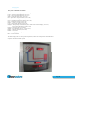
DF 120 – 6 SOLAR THERMAL COLLECTOR
Installation Guide
Issue date: 05/05/10
Issue version: 0.3
Web: www.stokvisboilers.com
Email: [email protected]
Installation Support Helpline: 020 878 33050
Page 1
Installation Guide—Contents
Page
Using this Installation Guide
Safety reminders and symbols
Transportation and handling
Installation Preparation
Solar system overview
Before starting the installation
Panel location(s), panel size and roof space required
Practical considerations
Sizing, replacing or converting the cylinder
Power supply
Safety considerations
Twelve Step Installation Guide
3
3
4
5
6
6
6
6
7
7
1 Check the kit contents
2 Prepare the panel
2a Panel preparation without fin angle adjustment
2b Panel preparation with fin angle
adjustment
Connection Possibilities
3 Fix the panel mounting
3a On a sloping roof
3b On a flat roof
3c On a wall
4 Mount the Panel
4a On a sloping roof
4b On a flat roof
4c On a wall
5 Run the pipework & sensor cable
6 Join pipework to Panel
6a Connection through a sloping roof
6b Connection through a wall
7 Install Internal Components
7a Pump station, expansion vessel & display unit
7b Air separator, isolation valve, AAV, drain cock & sensors
8 Fill, flush & test system
9 Install electrical protection
10 Set the solar controller
11 Configure for the customer
12 Commission and handover
8
10
10
10
11
14
14
14
14
16
16
16
16
16
17
18
19
19
20
21
22
23
23
25
25
Troubleshooting
Installation support
26
26
Appendix 1 —
Appendix 2 —
Appendix 3 —
27
31
32
Commissioning
checklist & sign off
Installers Notes
Kit contents specification
Page 2
Introduction
Using this Installation Guide
This guide describes the Ecotube system and recommended methods for its installation and
maintenance. It should be read and used in conjunction with the manuals supplied with, and
relevant to, the individual components.
Stokvis, suppliers of the Ecotube , recommends that all their products are installed by
properly trained and qualified personnel. These assembly instructions are written for specialists who are authorized to carry out solar thermal installations. The installer should have the
necessary basic skills and have the relevant accident prevention measures in place.
Installations have to be adapted to particular sites and responsibilit y for ensuring that the
installation is safe and fit for purpose rests with the installer.
Safety reminders & symbols
Key to Safety symbols used in this manual
DANGER!
DANGER!
Immediate danger to life & limb
Electrical Hazard
DANGER!
Risk of burns or scalding
DANGER!
Potentially dangerous situation for the product and environment!
The installer must follow their own Health & Safety procedures, in particular:
The accident prevention regulations for work on roofs should be observed at all
times.
Where appropriate use barriers to protect against drop hazard.
Use personal harnesses and/or protective scaffold as appropriate.
Care should be taken to avoid skin burns from contact with hot manifold piping when
installing panels in bright sunlight.
Never fill the system with water or perform a pressure test on it if there is a risk of
frost, even with air temperatures of 5 ° C frost damage could occur.
Page 3
Transportation and handling
Please note the following:
Transport the Ecotube panel horizontally to provide maximum protection of the tubes.
The panel should be carried by the mounting channels or boxed ends and not subjected to
twisting.
Use a suitable material to cover the panel if installing during
sunny weather.
Panel weight ( empty ) is 60 kg.
When handling the panel suitable protective gloves should be worn to protect against
sharp edges.
Installation Preparation
Solar System Overview
The Ecotube™ panel is made up of 6 evacuated glass tubes each containing a fin covered with
a special coating of Titanium-Nitrite Oxide. A copper tube filled with system solution passes
up the middle of a larger copper tube attached to the middle of each fin (see fig. 1). Solar radiation, direct and diffused, is absorbed by the fin coating and converted into heat. This heat
is carried by the system solution and pumped to the hot water cylinder during operation of
the circulation pump. The vacuum in the glass tubes eliminates convection and conduction
heat losses as well as protecting the collector from adverse weathering influences.
The water in the hot water cylinder is then heated by the system solution circulating from the
solar system and through a heat exchange coil near the bottom of the hot water cylinder.
Having dissipated its energy, the heat transfer liquid is pumped back to the solar panel for
reheating. This process continues provided there is a temperature difference higher or equal
to the pre-set value (usually 6 ° C) and the minimum panel temperature is reached (usually set
at 20° C). NOTE: If these conditions are not maintained the pump will switch off and the control unit will wait for the temperature of the panel to increase before restarting the heat
transfer process.
Page 4
Solar System Overview
Fig1. System schematic
OPTIONAL
DRAIN COCK
AIR SEPARATOR C/W AIR VENT
Page 5
Before Starting the Installation
Before starting an installation there is important preparation to do. Check the site and decide
on the number of panels required
This will depend on the size of the hot water cylinder, and the orientation of the roof and type
of building
Panel Location(s), Panel Size & Roof Space required
A key advantage of the Ecotube™ solar panel is that it can be installed at an angle on a
pitched roof, horizontally on a flat roof, or vertically on a wall to gain maximum exposure to
the sun’s rays. They can also be placed flat on a specially constructed pergola in the garden.
Ideally it should be as close to south facing as possible but if that is not possible a two panel
East/West system is also effective. Shading from buildings or trees should be avoided. Take
into consideration roof orientation, dormer positions (if any), and internal and external pipe
runs. Consult with the client as appropriate.
The dimensions of the Ecotube panel DF120 is 2905 x 860 x 150mm.
Practical considerations
Decide on how the roof can be safely accessed and the height of scaffold required. The installation can be carried out using scaffolding to roof height and roof ladders or by working from an
extended scaffolding platform. Examine ground conditions & hazards – i.e. ponds, brick walls,
slopes, in the area the scaffold is to be erected in. Arrange for the scaffolding to be erected.
The roof should be checked before installation to ensure that it is in a sound condition and is
capable of taking the weight of the panel(s). Check as applicable, for loose tiles or slates,
and soundness of roof supports.
Plan the optimum route of the pipe runs.
If the panel is to be wall mounted decide if it can be fixed directly to the wall or if it is necessary to use additional battens
Sizing, Replacing the Cylinder
The Ecotube system requires a hot water cylinder of a suitable size to prevent overheating of
the system during normal usage. The cylinder should either be a twin coil cylinder or a single
coil cylinder if used as a preheat store.
As a guide :
- 50 litres of dedicated solar storage is required per metre square of collector area. Dedicated storage is nominally 33%
of the total store volume – this applies for both a twincoil cylinder and a pre heat cylinder ie. the solar coil takes up the
lower 1/3rd of the cylinder.
The above will depend on DHW consumption and system efficiency when sizing systems and as a general rule a
minimum cylinder of 200 litres capacity is required for 1 pc DF 120 panel to prevent system overheat during periods of
high solar gain.
Page 6
Power Supply
A suitably rated power supply will be required dependent on the size of the circulation pump. If not already available this will need to
be installed by a suitably qualified engineer. The Resol Pump Station & Solar Controller requires a 230 V 1ph 50 Hz supply and is
suitable for most systems of up to 8 collectors.
Safety considerations
IMPORTANT:
DO A FULL HEALTH AND SAFETY ASSESSMENT BEFORE COMMENCING INSTALLATION
Each installation is different and the installer is responsible for ensuring that the installation is
carried out in a manner fully compliant with all Health and Safety Regulations and best practices. The points listed below are watchpoints to be taken in to consideration but may not
cover all eventualities.
Wear appropriate safety gear, high visibility jackets, hard hats, safety boots and gloves for
handling the panel and for use when cutting the flexible pipe.
Safe working practices must be adopted when on roofs following all guidelines set out by the
Health and Safety Executive. Care must be taken when erecting ladders on PVC guttering to
avoid damage. Scaffolding or tower scaffold should always be used when called for by existing Regulations. Arrange for the scaffolding to be erected, only erect scaffolding yourself if
you are qualified to do so.
Do not install on the roof, during adverse weather conditions, when the roof is wet or icy and
slippery, or when it is excessively windy.
Assess if there may be any danger to passers by: use cones and/or warning notices as necessary. If the install impinges on public areas (e.g. pavements) notify the appropriate authority
and arrange for the area to be cordoned off.
Consider how the panels can be hoisted safely. Make sure you have the correct equipment
and enough assistance.
Page 7
The 12 Step Installation Guide
Step 1: Solar rated items
Flowcon Pump station c/w
BS/3 Solar controller. If applicable
for up to 8 panels.
If applicable
Solar flexi hose 2 in 2.
Insulated flow & return
stainless steel corrugated
flexible pipes c/w integral
silicone two core sensor
cable.
The Pump Station includes isolation valves, an
inline flowsetter up to 13 litres/min, a check
valve,a pressure gauge, a fill & flush valve and
a 6 bar pressure relief valve.
Solar flexi is available in lengths of up to 25 metres.
Size range DN16 - ¾”. DN20 – 1” & DN25 – 1 ¼”.
Rubber Padstone 500 x 500 x 30
For flat roof panel mounting Cut into 4 sections.
Fixing clips for 2 in 2
Connections. St Steel
flexi to copper.
Expansion Vessel
Alternative
Pitched / tiled
roof Fixing
Screws
Expansion vessel
mounting kit. If applicable
Air Separator and
Automatic Air Vent
Installed on return pipework
off the solar store
Drain cock. Solar
System
Optional Solar display unit,
(SD3 smart display) + additional
sensor
Tyfocor LS System
Solution, Antifreeze,
Inhibitors
Roof flashings for
tiled / slated roof
If applicable
Page 8
STEP 1.
cont. Optional Pitched Roof mounting parts . Single Panel
Additional Installation Items
ROOF MOUNTING STRAPS.
1.2 Optional Extras
Depending on the project you may also have purchased some of the following:
Blending or TemperingValve, sized appropriately for the cylinder - a requirement to prevent scalding
TIPS
If the panels are stored before the start of an installation, they must be kept in a
dry location out of direct sunlight—use the packaging or a tarpaulin.
SAFETY REMINDER!
Exercise care when lifting heavy objects
Page 9
Step 2: Prepare the Panel
2a Panel preparation without Fin Angle Adjustment
1. Unscrew the 3 self tapping screws on the panel header box
2. Open the header box and carefully remove the top layer of heat insulation to reveal the
header pipe work and tube connections.
3. Using a drill or knife, make a hole in t he rubber around or between the pipes and push the
sensor inside the manifold.
4. Locate the panel sensor (S1) on the flow pipe (pipe closest t o the glass tubes) inside the
manifold just before the exterior flow pipe connection. It should be secured in direct
contact with the copper pipe using a jubilee clip. (See Fig 4)
5. Replace the heat insulation and header box lid and secure using the 3 self tapping screws.
6. Note the unique panel number and write it down on the warranty registration card.
7. Decide which of the four pipes exiting from the manifold will be used for flow and return
and fix 22 mm compression joints to these, blank off the other 2 pipes with 22mm stop
end compressions. Please note: the flow pipe is the copper pipe closest to the glass tubes,
the return pipe is the one furthest away from the tubes. To understand the connection
options please consult Fig. 2.
2b Panel Preparation with Fin Angle Adjustment
NOTE: The fin angle may only be set when the system is un-pressurized.
As far as is possible panels should be positioned to face South. The fin angle of the
vacuum tubes is pre-set to 30° which should be suitable for most installations
They can be rotated to the required angle. It is recommended that this procedure be carried
out before the panel is fixed on the roof or wall.
Situations where the fin angle will need adjustment are as follows:
A) Vertically mounted panel on a 40°pitch sloping roof that does not face exactly due south
— rotate fins to face due south.
B) Horizontally mount ed panel on a very steep sloping roof — alter fin angle to face 40° off
the horizontal (allow for the pitch of the roof).
C) Horizontally mounted panel on a vertical wall—alter fin angle to face 40° off the
Horizontal.
If you have a query about whether or not the fin angle needs adjustment please
phone our helpline on
020 87833050
Page 10
Fig 2. Connection Possibilities
The panels can either be installed vertically or horizontally, in both cases the connection can
be one sided or can alternate (see figs.1 & 2).
Fig 2a. Vertical Installation
Fig 2b. Horizontal Installation
– When carrying out horizontal installation with alternating connection it
Important
must always be ensured that the direction of flow is from the bottom of the panel to
the top to ensure venting.
– When carrying out one-sided horizontal installation the connecting pipes
Important
must be installed from above to guarantee venting.
Page 11
To alter the absorber fin angle please see following procedure (& fig. 2):
1. Unscrew the 3 self tapping screws on the panel header box
2. Open the header box and carefully remove the top layer of heat insulation to reveal the
header pipe work and tube connections
3. Carefully loosen the lower tube
compression nut (female nut A fig. 3)
from the upper manifold connection
(male connection B fig. 3), until the
tube rotates
Fig. 3 – Evacuated Tube Connections
Male connection
‘B’
4. Rotate the tube until required fin
angle is reached
5. Carefully tighten the lower tube
compression nut to the upper
manifold connection until tube is
unable to rotate, DO NOT over
tighten
Female comp.
nut ‘A’
6. Repeat steps 3 to 7 for each tube
7. Using a drill or knife, make a hole in the rubber around or between the pipes and push
the sensor inside the manifold.
8. The panel sensor should be located on the flow pipe (pipe closest to the glass
tubes) inside the manifold just before the exterior flow pipe connection. It should be
secured in direct contact with the copper pipe using a jubilee clip. (See Fig. 4).
9. Replace the heat insulation int o the header box and replace the header box lid
10. Screw the 3 self tapping screws back into the panel header box
11. Air pressure test the panel to 1 bar to check for leaks. An adapted garden pressure sprayer or small compressor can be used.
12. Decide which of the four pipes exiting from the manifold will be used for flow and return
and fix 22 mm compression joints to these, blank off the other 2 pipes with 22mm stop
end compressions. Please note: the flow pipe from the panel is the copper pipe closest to
the glass tubes
13. Note the unique panel number and write it down on the warranty registration card.
TIPS
: The panel flow connection is the copper pipe closest to the glass tubes,
REMEMBER
the return pipe is the one furthest away.
WARNING : Only change the fin angle if it is really necessary to do so. If you do be
extremely careful not to crack the compression nuts when loosening and tightening
them.
Page 12
TYPICAL 12 pc DF120 -6 SOLAR THERMAL COLLECTOR LAYOUT
Note : 2 panels removed to show typical
padstone layout..
PANELS JOINED USING 22mm to
22mm compression unions with
BRASS olives
Fig 4. Panel manifold end to show sensor position
RETURN
FLOW
Sensor
Female
compression nuts –
Stop
ends
–
dependent on AAV
connection.
Fig 5. Panel plan and elevation diagram showing mountings
The mounting rails can be adjusted if required by loosening the fixings and sliding the clamps
to suit the preferred pitch. Ensure that the clamps are tightened well once moved.
The mounting rails are provided with several 8mm wide slots to allow for diversity of fixing
centers.
Page 13
Step 3: Fix the panel mountings
The third step is to fix the mountings for the panel
3a. On a Sloping Roof
If the roof is sloping
1. Access the roof to locate rafters for fixings. Remove roof tiles where fixings are to go.
2. If possible use the straps provided as they offer more flexibility, only use the specialist
roof fixing bolts when you cannot move the slates or tiles.
3. Fix the straps to the rafters with an assistant in the loft using suitable wood screws.
Ensure the fixing centres are the same distance apart as the fixing centres of the panel
mounting channels. Choose suitable fixing slots according to site conditions. An 86 cm
length can be used acroos the panel mounting channels if the panel is to be installed
vertically.
TIPS
Although it is sometimes impossible to avoid standing on tiles/slates, keep this to a
minimum and try not to put on your full body weight. Apart from the danger of slipping, a cracked tile or slate means unnecessary repair work.
At least four tiles should be left clear from top connection to ridge, for ease of working on pipe connections inside the roof space.
3b. On a Flat Roof
If you are putting the panel on a flat roof:
1. Saw the rubber padstone (supplied) into 4
2. Place the 4 resultant, smaller, padstones on the roof, spaced so that the mounting
channels (see Fig. 5) will rest centrally on them.
3. There is no need to secure the panel to the roof.
3c. On a Wall
If the panels are to be wall mounted
1. Measure the centres of the panel mounting channel slots (see Fig. 5).
2. Drill two holes into the wall at this distance apart.
3. Install suitable shield anchors.
STEP 3C TIPS
If the wall substrate needs reinforcement we suggest the use of 41mm x 21mm unistrut
(not supplied) fixed to the wall with appropriate fixings and then the panel can be fixed to
the unistrut.
A slight rise should be allowed for at the manifold end to assist in venting.
Page 14
Fig 6. Pitched Roof solar panel mounting schematic - Side View
2 pc Straps
TWISTED END SECURED
TO RAFTER
Fig 7. Pitched Roof solar panel mounting schematic—Plan view
Top of roof
Builders
Panel
Mounting
Channels
NOTE :
Tiles removed to
show detail
Rafters to suit solar panel
fixing centres + - 2100 mm
Page 15
Step 4: Mount the Panel
The fourth step is to attach the panel to the mountings
Step 4a. On a Sloping Roof
If the roof is sloping:
1.
2.
3.
4.
Hoist panel to roof level and slide the panel up the roof to the fixings.
Ensure the fins are facing the correct way.
Lift the panel into position on the mounting straps / bolts.
Fix the panel in position.
Step 4b. On a Flat Roof
If you are putting the panel on a flat roof:
1. Hoist the panel up to the roof and place on the rubber padstones
2. Ensure the fins are facing the correct way.
3. No securing to the padstones is necessary.
Step 4c. Wall Mounted
If the panel is to be wall mounted
1. Hoist the panel up and position on the wall mountings or shield anchors.
2. Ensure the fins are facing the correct way.
3. Secure the panel in place by fixing to the shield anchors.
TIPS
W hen hoisting the panel, it is quite useful to take the weight by a rope slung over the
ridge tiles and finally tied to a ground fixing or chimney stack. This allows fine
adjustment and marking of fixing point s with no danger of the panel slipping.
The Ecotube panels can be hoisted by the manifold end using suitable slings / rope
with care. NOTE: Do not allow panel to twist during hoisting as this can damage the
connections within the manifold.
Avoid exposing the vacuum tubes of the panel to strong sunlight during installation,
keep covered with a suitable cover until the system is filled with water. Prolonged exposure, without water, may damage the panel.
SAFETY WARNING!
Mounting the panel on the panel mountings is a job requiring at least two able
persons. Carry out a risk assessment prior to hoisting up the panel.
Page 16
Step 5:
Run Pipework and Sensor Cable
The fifth step is to run the pipework & cable through the property.
1. The tubing of the flow and return lines must be carried out using copper tubes (as per
DIN 1786) or approved systems.
2. Stainless Steel DN16 2 in 2 can be installed directly to the panel with the appropriate
fittings for up to a 6 panel installation. The heat insulation materials must be able to withstand temperatures
of up to 160°C.
The use of this hose is recommended in order to reduce the number of joints ( and therefore the risk
of leaks) and also to enhance the fin ished appearance of the installation.
3. You will already have decided on the shortest and least disruptive route from the panel
to the cylinder through the property for the pipework and sensor cable.
4. Make sure the pipework is neatly fixed to the property where necessary
5. When considering connection possibilities for a panel on a sloping roof consult Fig. 2.
No. of collectors
1 - 10
11 - 17
18 - 27
28 - 40
41 - 70
71 - 110
111 - 160
161 - 280
Table A
Max. flow rate
20 l/min
35 l/min
55 l/min
80 l/min
140 l/min
220 l/min
320 l/min
560 l/min
Req'd. pipe Size
Ø22
Ø28
Ø35
Ø42
Ø54
Ø67
Ø76
Ø108
TYPICAL PIPE SIZES FOR VARIOUS FLOWRATES
Page 17
Step 6: Join Pipework to Panel
The pipework now needs to be connected to the panel through the roof or wall, depending on
the location of the panel
STEP 6a Connection Through a Sloping Roof
1. The penetration through a sloping, tiled roof should be made using the lead flashing plates. Note the
flashings will accept 22mm to 54mm pipework by cutting the silicone nipple accordingly.
2. Locate where to drill your holes from inside the roof so as to miss the roof joists.
3. Drill the holes through the tiles (we advise drilling pilot holes first to minimise the chances
of breaking tiles).
4. Lay the lead flashing over the tile with the hole.
5. Cut a suitable hole (smaller than the pipework) in the top of the red part of the flashing
plate.
6. Push the pipe through into the loft .
7. Ensure the roof is water proof and the flashing is flush around the edges of the tile.
8. Repeat this process for the other pipe.
9. Don’t forget the small hole for t he sensor cable.
Fig 9. Sloping roof solar panel mounting schematic with pipe work penetration detail
Plan View
2pc Roof Flashing Plates
with Silicone Gaiters
Top of roof
Flow pipework and
sensor cable
NOTE :
Tiles removed to
show detail
Return pipework
Page 18
STEP 6b Connection through a wall
1. For a flat roof installation if possible run the pipework over the edge of the roof and
penetrate the wall as for a wall installation.
2. If the pipework must penetrate a flat roof, consult a roofing contractor to ensure a
waterproof finish.
3. To penetrate an exterior wall drill suitable size holes for sleeves to accept the flow and
return pipework and another, smaller, hole and sleeve for the sensor cable.
4. All pipes should be sleeved through the full thickness of the wall.
5. Waterproof the installation using a suitable silicone sealant
WARNING!
Do not penetrate a flat roof. If it is not possible to run the pipework over the edge and
through a wall consult with a roofing contractor t o ensure a water-tight finish
Step 7: Install Internal Components
7a Pump Station, Expansion Vessel and Display Unit
The pump station should, ideally, be installed adjacent to the hot water cylinder so information on syst em status can be observed in relation to system pressure, system temperature
and system flow. The pump station should be located where he customer can clearly see and
access both the solar controller and the system pressure gauge.
The expansion vessel is normally installed directly off the pump station. If necessary the expansion vessel can be mounted in the roof space (loft) with a suitably extended run of pipework from the pump station to the expansion vessel.
The Display Unit should be mounted where it is easily visible. Consult with the client as to t he
exact location. It will be connected to the solar controller with the bell wire (supplied) so consider where this can be run unobtrusively.
Fix the Pump Station and precharge the Expansion Vessel
1. Securely fix the pumpstation to the wall.
2. Run a pipe from the pressure relief valve to a suitable drain or container.
(the empty Tyfocor container for a small system).
3. The pump station will require a 13A socket. If not already available this will need to be
installed by a suitably qualified engineer
4. Before being secured the expansion vessel precharge pressure must be set.
1 barg pressure is required at the furthest panel from the riser. Precharge pressure needs to be set 0.2 bar
lower than the resultant working pressure taking into consideration the geodetic pressure
( height of the panels in relation to the expansion vessel location ).
Page 19
Installing
Connect the Panel, Pump Station & Cylinder – Up to 8 panels – basic small system.
5. Run the flexible, ready insulated stainless steel flow pipes (flexi pipe) supplied directly
from the panel through the roof and down to the solar coil flow connection on the cylinder.
6. Join the flexi pipe to copper pipework ( between the cylinder solar coil lower return connection and the pump station )with the connectors supplied as follows:
A. Wearing a pair of safety gloves cut the flexi to the required length
B. Slide on the nut and fix the circlip round the last groove on the pipe.
C. Tighten the flexi-copper flat edge up to the nut.
D. Release the nut to reveal the flanged end on the flexi pipe.
E. Insert the washer and tighten back up.
WARNING-once cut the pipe is razor sharp.
Install the OPTIONAL SD3 Display Unit
7.
Mount the SD3 display unit following the mounting
instructions in the SD3 box.
8.
Take the supplied 10 metre length of 2 core bell
wire and connect one end to the V-bus output in the
solar controller.
9.
Run the bell wire to the SD3 display.
10.
Connect the remaining end of the bell wire to the VBus connection in the back of the SD3 display unit.
7b Install Air Separator, Isolation Valve, Automatic Air Vent,
Drain Cock and Sensors
1. Attach the return solar connection on the cylinder with 22mm compression connections
to the air separator (this should be fitted in a horizontal position) fitted with the Isolation
valve and Automatic Air Vent . See 6. Above.
2. The drain off cock should also be located on t his return pipe at the lowest point of the
system (usually next to the return solar cylinder connection).
3. This return connection from the cylinder is connected to the bottom of the pump station
4. The return pipe to the panel should run from the top of the pump station.
Automatic Air Vent
Isolation Valve
Air Separator
Page 20
Fit sensors
5.
6.
The S1 sensor should already have been installed inside the manifold box on the flow
pipe where the top tube joins the manifold. Use a suitable connection block to join the
S1 sensor lead to the lead in the centre of the twin core solar pipe.
Install the S2 sensor on the cylinder – this is normally positioned in the pocket provided
on most cylinders located in the middle of the solar coil. If a pocket is not provided, use a
knife or chisel and carefully remove a section of the foam insulation, insert the sensor
against the cylinder ensuring good contact and re-cover with the insulation that you removed.
7.
Install the S3 sensor on the top of the cylinder. If no pocket exists it can be st rapped to
the hot draw-off pipework as close to the cylinder as possible. This sensor is normally
used to give an indication of the temperature at the top of the cylinder. ie. Temperature
potentially going to the taps (via the blending valve)
8.
Install sensor for display unit (p/n. FRP6) to return pipe work beneath pump station using a cable tie or jubilee clip.
STEP 7 TIPS
If the pressure vessel is set up incorrectly, the system will over pressurise and vent off.
Only insulate the connection between the pump station & the expansion vessel if there is a
risk of burns to the customer.
The lower sensor S2 needs to be installed on the cylinder at the mid point of the Solar coil.
Depending on the type of cylinder or heat exchanger it is critical to place this sensor in the
correct position to ensure efficient operation of the system.
WARNING!
Once cut the flexi pipe is razor sharp. Wear gloves when handling.
Page 21
Step 8: Fill, Flush and Test the System
1.
Use a fill and flush pump to fill the system with water via the fill/flush points on the pump
station.
2.
Pressurise the system to ( minimum )3 bar for 20 minutes to test for leaks. Large systems on tall buildings will require tested to suit design
pressure.
3.
Check all joints for leaks, drain and repair if necessary, and retest
4.
When draining disconnect the electrical supply to the pump station to isolate it.
Use the drain points on the pump station or the drain cock on the return pipework adja cent to the cylinder to drain the system.
5.
Drain the system and flush through with mains water to remove any loose scale or contaminants.
6.
Refill the system with the Tyfocor provided. Open the Automatic Air Vent (AAV). Reconnect electrical supply.
7.
Pressurise the system to the operational design pressure
8.
Run the pump on manual operation. Check all the joints again.
9.
Top up as necessary to maintain design pressure as air is expelled through the AAV
10. Set the flowrate at 1.5 litre/minute per panel using the manual flowsetter on the pump station.
or panel banks if installed on large systems.
11. When satisfied that all air has been expelled close the AAV
12. Set the controller to AUTO operation.
The System should now be operational the green light should be
ON
STEP 8 TIPS
Use the drain points on the pump station or the drain cock on the return pipework adjacent
to the cylinder to drain the system.
WARNING!
When draining disconnect the electrical supply to the pump station to isolate it.
Page 22
Step 9: Install Electrical Protection
For general electric shock protection:
1. Link the panels together so that they are electrically equal.
2. Connect the solar tubing (flow and return) within the buildings earthed equipotential
bonding zone, using a short line. (this would normally be done via the equipotential
bonding in customers cylinder cupboard )
3. If there is lightning protection in place in the building, large metal parts (e.g. the collector housing) must be connected to it.
4. Please also observe the assembly instructions issued by the control system manufacturer.
5. Work must always be carried out by an authorised specialist.
Step 10: Connect and Set Solar Controller
Step 10: Set the Solar Controller . Small system
1. Connect the Solar Controller to the various sensors by
plugging in wires from the sensors to the correspondingly
numbered points on the controller.
i.e S1 from the panel sensor
S2 lower cylinder sensor
S3 top of cylinder sensor
S4 return flow sensor (before pump station)
2. Connect the Solar Controller to the SD3 display unit
with supplied 10 metre length of 2 core bell wire. Connect
one end to the V-bus output in the solar controller, run
bell wire to the V-Bus connection at the back of the SD3
display Unit.
Setting the BS3 Controller
Use the backwards and forwards buttons to scroll through
the menu. Using the forward button go straight to “current time”
setting and set the time by holding down the centre “set” button
until the set sign flashes and then using the forward and backward
buttons set the correct time. Once correct, hold down the set button
until the “set” sign stops flashing in order to save the time selected.
Next hold down the forward button until AAR 1 shows then follow the
Procedure in paragraph 2:
Definitions
backwards
COL = collector temp erature
TST = lower tank temp
S3 = upper tank temp
S4 = return temp
HP = total operating hours of solar pump
Time
set forwards
Page 23
Paragraph 2.
Set your controller as below:
ARR1 = standard solar system (use this setting)
DTO = switch on temp difference (set of 6)
DTF = switch off temp difference (set of 3)
SMX = maximum store temp (set to 70)
EM = panel max t emp shut down (set to 140)
OCX = collector cooling (set to off)
OCN = minimum limitation collector (set to off)
OCF = antifreeze collector (set to off)
OREC = option re-cooling (set to off)
OTC = option tube collector (set to off)
OHQM = heat quantity measurement (this is used for the remote display, set to on).
(If not using the display switch to off)
FMAX = flow rate (set to1.5 ltr.min)
MEDT = heat medium (set to 3 = Tyfocor LS)
HND1 = manual operation (set to auto)
HND2 = set to Auto
LANG = language (EN=English)
BS3 = version number
The SD3 display will now show panel temperature, bottom store temperature and total kW hr
output for the solar thermal system.
Page 24
Step 11: Configure for the Customer. Small systems
Configure the system to meet the Customer’s needs
1. To customize the system for the client you need to understand when the customer
normally uses hot water and how much is typically used. Consider baths, showers,
washing up, washing machine (if hot fill) etc
2. Suggest a time programme for the boiler that meet s the hot water needs of the
customer. This will typically involve the solar gain through the day topped up by the
boiler to ensure evening and morning hot water needs are fulfilled. e.g. depending on
the time of year, set the timer to run the boiler until the cylinder is at the required
temperature during the night to ‘top up’ the solar gain in advance of showers the
following morning.
3. Set the thermostat on the cylinder to 65°C
4. To be sure the system is fully operational go through, and fill in, the commissioning
checklist in Appendix 1.
WARNING!
A risk assessment should be carried out to ensure that the cylinder temperature is taken above 60°C
at regular intervals to guard against Legionella risk.
Step 12: Commission and Handover
1. Complete and sign the commissioning checklist
2. Make sure the customer understands the system.
2. Explain the readings on the display (or solar controller if no display is inst alled) with
particular emphasis on S3, the cylinder temperature
3. Make sure the warranty registration card is filled in and the customer has the user manual.
Job Done!
Page 25
Troubleshooting
Problem Cause Action
No power to the controller
1. Faulty/blown fuse in mains supply.
1. Check wiring and replace fuse
2. Faulty/blown fuse in control unit.
if required with 3amp in p lug.
2. Check and replace fuse if required with
4amp circular fuse in controller fixings
3. Circuit breakers/fuses tripped in
kit.
3. Check wiring and reset.
house.
4. Power cut.
4. Wait until power is restored.
Sensor fault indicated by:
1.
symbol
2. 888.8 disp layed for sensor
3. -88.8
Pump will not run
No circulation in system
Pressure drops in system
1. Faulty sensor.
1. Check/Change sensor.
2. Loose connection on sensor lead s.
2. Check sensor wires for
connection.
3. Short circuit.
3. Check the line.
1. Mains/pump wiring faulty.
1. Check wiring at mains/pump.
2. Pump rotor jammed.
2. See pump manufacturers instructions.
3. System parameters EM exceeded.
3. Cover solar panels and allow to cool.
4. CMN and DTO not satisfied.
4. No action required.
1. Pump isolating valves closed.
1. Open valves.
2. Air lock at pressure relief valve.
2. Twist cap at pressure relief valve and
vent air (if accessible).
3. Air lock in the system.
3. Check all pipe work rises on return
side and falls on flow side. Clear
manual air vents.
4. Pump is not running.
4. See above.
1. Leak in system.
1. Check all joints.
2. Drain down valve not closed.
3. Pressure relief valve not fully
2. Close fully.
closed.
3. Clean and replace if necessary.
Installation Support
Call the Installation helpline: 020 87833050
Page 26
Appendix 1
—Commissioning Checklist
Commissioning Checklist & Sign Off
Client Name & Address:
Site Address (if different):
Page 27
Commissioning Checklist cont.
Panel and Roof
Yes No N/A
1. Panels secured
2. Roof tiles replaced and secure
3. Sensor securely fixed
4. Water-proofing checked
5. Insulation OK
Solar
Yes No N/A
1. All joint s checked for leaks
2. Anti-freeze added frost protection
on controller switched to off
3. All pipe work securely supported
4. AAV valve closed
5. Manual air vents cleared and closed
6. Drain cocks closed and tightened
7. Check valve bleed screw closed
8. Pump correctly fitted
9. Pump isolating valves fully open
10. Pump setting correct/flow meter
set – 1.5 litres/min per panel.
11. System pressurised to design pressure
12. Filling loop closed
13. Filling loop disconnected
14. Pressure relief valve cleared
15. No isolating valve between panels
and safety valve
Page 28
Commissioning Checklist cont.
Primary – Auxiliary (if appropriate)
Yes No N/A
1. All joint s checked for leaks
2. AAV Open
3. Manual air vents cleared
4. Drain cocks closed and tightened
5. Radiators cleared of air
6. Header tank ball valve operating
7. Header tank insulat ion replaced
8. Boiler operation checked
9. Radiators checked
10. Hot water checked
Secondary
Yes No N/A
1. All joint s checked
2. Cold tank filled
3. Cold tank ball valve operating
4. Gate valves open
5. Cold tank lid and insulation replaced
6. Water at all taps
7. 3-way diverter valve correct ly fitted
(if applicable)
8. Thermal mixing valve fitted. If applicable.
Page 29
Commissioning Checklist cont.
Electrics
Yes No N/A
1. CH/HW controller reset
2. Immersion heater connected and
tested
3. 13A socket to solar controller test ed
for correct polarity.
4. Tank and reference sensors tested
securely positioned
5. Electric wires clipped and tidy
6. Sensors test ed on controller
7. Controller temperature settings
correct
8. Pump setting on AUT
Mains Water Supply
Yes No N/A
1. House stop cock open
2. Primary header tank stop cock open
3. Cold tank stop cock open
Insulation
Yes No N/A
1. All pipe work insulated
2. All insulation securely taped
Tidy Up
Yes No N/A
1. All dust sheet s removed
2. All packaging in vehicle
3. Indoor work areas cleaned
4. Outdoor work areas swept
Page 30
Appendix 2—Installers Notes
Comments:
Installing Engineer:
.............................................................. Sign
.............................................................. Print
.............................................................. Date
Site Specific Additional Details:
Electrical Supply Isolation
Specialist Information
Collector Manufacturer & Model:
Controller Manufacturer & Model:
Cylinder Manufacturer & Model:
Resol
Page 31
Appendix 3— Specification
A3.1 Ecotube™ Panel(s) DF 120.
Dimensions - 2923 x 842 x 155
Weight - Empty - 60kg - Full - 62kg
Net aperture area - 1.799m²
Net absorber area - 1.715m²
Performance (Swiss testing station)
1597 kWh / panel / year
888 kWh / m² / year
Performance (UK)
1365 kWh / panel / year
767 kWh / m² / year
Gas displacement - CO2 / year
264.8kg
Electricity displacement - CO2 / year 576 kg
Number of tubes – 6
Diameter of tube - 120mm
Solar Keymark (registration no.) - 011-7S684 R
Conformance - DIN EN12975
Microgeneration Certification Scheme - MCS1255
A3.2 Pump station & Solar controller - Suitable for up to 6 panels.
Single & Double panel systems: Flowcon A Pumpstation c/w BS/3 Solar controller.
Single line pump station, dial pressure gauge, 6 bar pressure relief valve, flowmeter, fitted
with manual air vent, filling and flushing unit , wall mounting kit, insulated casing.
Resol Delta Sol BS/3 Controller - easy to read multi-display screen with backlighting that
allows the user to view the operating status of the system.
East/West System: Flowcon D2F Pumpstation, BS plus Solar Controller.
Three line pump station, flow and return thermometers, dial pressure gauge, 3 or 6 bar
pressure relief valves, flowmeter, filling and flushing unit, wall mounting kit, insulated
casing.
Resol Delta Sol BS plus Controller - easy to read multi-display screen with backlighting that
allows the user to view the operating status of the system.
Page 32
A3.3 10m – Other lengths available )DN16 21N2 preinsulated, flexible, Solar Hose.
Flexible hose with integral insulation enables protected pipework to be run with minimum
joints reducing risk of leaks as well as enhancing finish and improving installation time.
Technical Data:
- Insulation: 150°C resistant closed cell EPDM, thickness 14mm, thermal conductivity
=0.038W/(mK).
- Sensor Cable: 2 core, 0.75mm2, silicone rubber 175°C.
- End fitting BSP t hread 3/4”, Max working pressure @20°C 16 bar, Dimensions W x H
90 x 50 mm.
Set of 4 Solar Hose fixing brackets (set of 8 for East/West system), pack of fittings for
stainless flexihose (2 of for E/W system).
A3.4 Expansion Vessel c/w mounting bracket with quick release coupling.
Protects the system under stagnation conditions.
Quick release coupling means EV can be serviced without system draindown.
A3.5 Tyfocor LS System Solution
Ready mixed antifreeze affording protection to -28°C with a continuous t emperature capacity of 170°C.
A3.6 Automatic Air Vent
DZR Brass casing with stainless steel float. Can withstand continuous temperature
of 150 deg C.
Isolation Valve, Air Separator.
A3.7 Smart display SD3
SD3 smart display with 3 7 segment displays for indication of the system temperatures and
heat quantity of the solar system.
A3.8 Panel Mounting Kit
Pitched Roof: LS2 Solar Roof Flashings set of 2 (set of 4 for E/W system), HT Insulation,
Roof straps and fixings (2/panel
Flat Roof: Rubber padstone 1 pc 500mm x 500mm x 30mm thick to be cut into 4 equal
squares.
Wall Mounted: Wall hanging brackets and fixings (Not supplied)
A3.9 Documentation
Installation Guide
Users Manual
Important User Notes (for fixing by Solar Controller)
Warranty Registration Card
Page 33