1
M0100
SOLOS
(tm)
/CUTER
(tm)
USER'S MANUAL
PROCESSOR TECHNOLOGY CORP.
6200 Hollis Street
Emeryville, CA 94608
SOFTWARE TECHNOLOGY CORP.
P. O. Box 5260
San Mateo, CA 94402
(415) 652-8080
(415) 349-8080
(C)
1977 by Processor Technology Corporation
I M P O R T A N T
N O T I C E
This copyrighted software product is distributed
on an individual sale basis for the personal use
of the original purchaser only. No license is
granted herein to copy, duplicate, sell or otherwise distribute to any other person, firm or
entity. This software product is copyrighted and
all rights are reserved.
S O F T W A R E
W A R R A N T Y
Software Technology-Corporation warrants this Software Product to be
free from defects in material and workmanship for a period of three
months from the date of original purchase.
This warranty is made in lieu of any other warranty expressed or
implied and is limited to repair or replacement, at the option of
Software Technology Corporation, transportation and handling charges
excluded.
To obtain service under the terms of this warranty, the defective
part must be returned, along with a copy of the original bill of
sale, to Software Technology Corporation within the warranty period.
The warranty herein extends only to the original purchaser and is not
assignable or transferable and shall not apply to any software
product which has been repaired by anyone other than Software
Technology Corporation or which may have been subject to alterations,
misuse, negligence, or accident, or any unit which may have had the
name altered, defaced or removed.
P R E F A C E
This manual describes the use and operation of either
(tm)
(tm)
SOLOS
or CUTER
. SOLOS is a program designed to
(tm)
be a personality module in a Sol
. CUTER is a
program designed to provide much of the power of SOLOS
for the non-Sol user.
Because SOLOS and CUTER have
been designed to be compatible operating systems, this
manual will refer to SOLOS meaning the SOLOS/CUTER
operating system.
The few differences between SOLOS
and CUTER will be stated explicitly.
(tm)
SOLOS, CUTER and Sol are trademarks of Processor Technology
Corporation.
i
SOLOS/CUTER User's Manual
TABLE OF CONTENTS
I. INTRODUCTION
Definition of Terms
Quick Command Reference List
. . . . . . . .
. . . . . . . .
1
2
. . . . . . . . .
4
.
.
.
.
.
.
.
.
.
.
4
4
4
5
5
. . . . . . . . .
6
.
.
.
.
.
.
.
.
7
7
7
7
. . . . . . . . .
9
II. CONSOLE COMMANDS
Console Commands in Brief
Console Commands in Detail
Execute Command
Enter Command
Dump Command
Terminal Command
Custom Command
.
.
.
.
.
.
.
.
.
.
.
.
.
.
.
.
.
.
.
.
.
.
.
.
.
.
.
.
.
.
.
.
.
.
.
III. TAPE COMMANDS
Tape Commands in Brief
Tape Commands in Detail
Get a File from Tape into Memory
Get, then Execute
Save a File
Catalog a File
IV.
.
.
.
.
.
.
.
.
.
.
.
.
.
.
.
.
.
.
.
.
.
.
.
.
.
.
.
.
SET COMMANDS
SOLOS' Ten Set Commands
Set Commands in Detail
Set Speed of Display
Input/Output Commands
Set Out Command
Set In Command
Set Tape Command
Set Type Command
Set Execute Command
Custom Input/Output Commands
.
.
.
.
.
.
.
.
.
.
.
.
.
.
.
.
.
.
.
.
.
.
.
.
.
.
.
.
.
.
.
.
.
.
.
.
.
.
.
.
.
.
.
.
.
.
.
.
.
.
.
.
.
.
.
.
. . 9
. . 9
. . 9
.
10
.
10
.
11
.
11
.
11
SOLOS/CUTER User's Manual
TABLE OF CONTENTS (cont.)
IV.
SET COMMANDS (cont.)
Set CRC Error Checking Command
Set Number of NULLS Command
. . . . . . . .
. . . . . . . .
12
12
Introduction to SOLOS Machine
Language Interface
Pseudo Ports for SOLOS
Pseudo Ports for CUTER
Defined Register Usages
SOLOS Jump Table – Defined
Jump Table
.
.
.
.
.
.
.
.
.
.
.
.
14
14
14
15
15
16
System Entry Points
. . . . . . . .
17
. . . . . . . .
. . . . . . . .
17
17
SOUT
AOUT
. . . . . . . .
. . . . . . . .
17
18
SOLOS VDM Display Driver
. . . . . . . .
18
. . . . . . . .
19
File Header
Block Access
Read Tape Block Routine
Write Tape Block Routine
Byte Access
File Open Routine
Write Byte Routine
Read Byte Routine
Close File Routine
.
.
.
.
.
.
.
.
.
.
.
.
.
.
.
.
.
.
19
20
20
21
21
22
22
23
23
LOADING & EXECUTING CUTER
. . . . . . . .
24
SUBROUTINES
A.
B.
.
.
.
.
.
.
.
.
.
.
.
.
.
.
.
.
.
.
.
.
.
.
.
.
.
.
.
.
.
.
.
.
.
.
.
.
C. SOLOS Input Entry Points
SINP
AINP
D. SOLOS Output Entry Points
E.
F. Cassette Tape Entry Points to SOLOS
VI.
iii
.
.
.
.
.
.
.
.
.
.
.
.
.
.
.
.
.
.
.
.
.
.
.
.
.
.
.
.
.
.
.
.
.
.
.
.
.
.
.
.
.
.
.
.
.
.
.
.
.
.
.
.
.
.
I.
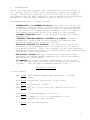
INTRODUCTION
SOLOS is a 2048 byte program that configures the Sol-20 and one or
two cassette tape recorders into a powerful, stand-alone computing
system. SOLOS takes advantage of the Sol-20's built-in hardware
peripherals and the 8080 instruction set to optimize the convenience
and power of the inherent computer capabilities of the Sol.
Outstanding features of SOLOS include...
•
•
•
•
•
•
STANDARDIZED I/O SOFTWARE PROTOCOL which makes all Sol-20 I/O
(keyboard, display, serial, parallel and cassette) accessible
to external programs from one entry point--a standard feature
in all future Sol system software products that will require
less memory than would normally be used for I/O routines.
SOFTWARE INTERFACE permits user defined routines for custom
applications.
"INDUSTRY STANDARD-SETTING" CASSETTE I/0 CONTROL includes
methods for loading and saving programs and commands that
execute programs after automatic loading.
EXCLUSIVE CASSETTE I/0 ROUTINES allow cassette files to be
accessed on a byte-by-byte basis as though each file were a
byte-by-byte device. Thus, data transfer to and from cassettes
appears as normal I/O--and two cassettes can be used simultaneously
to assemble and edit programs.
NEW DISPLAY CONTROL features found only in expensive video
terminals--including ESCAPE sequences for cursor positioning
and character speed control.
19 COMMANDS to access the basic requirements of the Sol-20
control cassette tape recorders and set up special conditions
in SOLOS. (See the "Quick Command Reference List".)
Definition of Terms
In this manual:
addr means word address hexadecimal characters, (0-FFFF)
range
data means hexadecimal characters, (0-FF) range
file means a collection of data
name means any one to five character identification for a
file
port means a SOLOS pseudoport from 0 to 3
unit means a number of 1 or 2 corresponding to the
appropriate tape recorder
(
) means optional parameters
1
INTRODUCTION (cont.)
Only the first two letters of the command expressions must be
typed when entering a command expression. (The underscored
letters in the following Quick Command Reference List.)
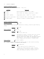
Quick Command Reference List
COMMAND
FUNCTION
Console
EXEC
ENTR
DUMP
TERM
CUST
addr
addr
addr1 (addr2)
(portin (portout))
name (addr)
Begin program execution at 'addr'
Enter data into memory starting at 'addr'
Dump memory data, 'addr1' to 'addr2'
Enter Terminal Mode
Insert or remove a custom command
Tape
GET (name(/unit) (addr))
Get a tape file into memory
SAVE name (/unit) addrl addr2
(addr3)
Save a file from memory to tape
XEQ (name(/unit) (addr))
Get then execute a tape file
CAT (/unit)
Catalog tape files
Set
SET S=data
Screen character rate
SET I=port
Input port to SOLOS
SET O=port
Output port to SOLOS
SET N=data
Number of NULLS following CRLF
SET XEQ addr
Auto-execute addr
SET TAPE 0 or 1
0=1200 baud, 1=300 baud
SET TYPE data
Type 'byte' header
SET COUT addr
Custom output addr
SET CIN addr
Custom input addr
SET CRC data
Allows ignoring of tape CRC Read Errors
2
I.
INTRODUCTION (cont.)
With a Sol, or CUTER on a Processor Technology GPM board, a poweron performs a reset which causes a SOLOS system reset. The Sol
user may initiate this system reset anytime by simultaneously
pressing the upper case and repeat keys.
A SOLOS system reset enters SOLOS into COMMAND mode. When in COMMAND
mode, SOLOS will do a Carriage Return-Line Feed (CRLF) followed by a
prompt (>). SOLOS then awaits the entry of a COMMAND. A COMMAND is
processed upon receipt of a Carriage Return (CR). Pressing the MODE
(or Control-@) key while awaiting a COMMAND causes the current COMMAND
input line to be ignored and return to COMMAND mode. CUTER also
resets the current I/O pseudo port selections to the system default.
The MODE (or Control-@) key is also used to abort the execution of
most commands. This use of the MODE (or Control-@) key turns off
both tape machines (if on) and returns to COMMAND mode.
3
II.
CONSOLE COMMANDS
Console Commands in Brief
SOLOS has five console commands.
They are:
Command
Function
EXEC addr
Begin program execution at 'addr'.
ENTR addr
Enter data into memory starting at 'addr'.
DUMP addrl (addr2)
Dump memory data, 'addr1' to 'addr2'.
TERM (portin (portout))
Enter Terminal Mode (available under SOLOS only)
CUST name (addr)
Insert or remove a custom command.
Console Commands in Detail
Execute Command
EXEC addr
This command begins program execution at memory location specified by
(addr).
Example:
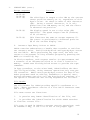
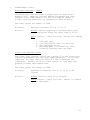
Enter Command
EXEC 200
ENTR addr
Example:
ENTR 500
: C3 00 01 1000: 05/
Result:
Dump Command
Beginning at memory location 500, the following data was entered: C3 00 01. The new
memory location of 1000: was selected to enter
the data 51. The slash (/) terminated the
ENTR command and returned to command mode.
DUMP addr1 (addr2)
This command displays sequential memory data on the screen starting
at location (addrl) and ending with (addr2).
Example:
DUMP C02E C037
Result:
C02E E1 DB FA 2F E6 01 C8 DB FC C9
Dumped the SOLOS keyboard input routine.
(See listing.) Starting at memory location
C02E and ending at memory location C037.
4
II.
CONSOLE COMMANDS (cont.)
Terminal Command TERM (port-I (port-O)) (Available under SOLOS only)
This command causes the Sol system to become a video terminal for
connection to an external computer or modem. This command begins
by automatically setting the I/O pseudo ports to the specified
values. An omitted port parameter will be set to 1. Execution then
proceeds by sending all Sol keyboard entries (except cursor control)
to the specified Output pseudo port. Any input available from the
Input pseudo port will be processed by the SOLOS display driver.
Example:
TERM
Result:
Keyboard data will be sent to the serial
port and all data from the serial port will
appear on the display screen.
Custom Command
CUST name (addr)
definition/removal
When a non-SOLOS command is entered, a separate table of custom
commands (in RAM) will be searched. The CUST command is used to
enter and remove up to six custom command names from the custom
command table. (Only the first two letters of the name are significant.) When the name (2 to 5 letters) specified by the CUST
command is not already in the custom command table, a new custom
command will be entered into the table having an execute address as
specified. When the addr is not specified, the beginning address of
SOLOS will be used.
When the name specified on the CUST command already exists in the
custom command table, this table entry will be replaced with an
'end-of-table' indicator. Therefore, not only will the specified
name be removed, but any other custom command names following in the
table will also be removed.
Example:
CUST BASIC 0
CUST ALS8 E060
Result:
Two new custom commands are now known.
ALS8 at location E060, and
BASIC at location 0.
5
III.
TAPE COMMANDS
Tape commands are used to control the tape cassette recorders. In
these commands, unit selection is optional, with a default selecting unit 1. When a unit is specified, however, it must be separated
from the file identification name with a slash (/) and without
spaces in between: e.g., TARGT/2.
Tape Header
At the start of each tape file is header information.
tion includes the following data:
This informa-
name:
name of file, 5 ASCII characters or less
type:
number is specified by user at time file is created
addr:
starting address of file
size:
number of data bytes in file
XEQ addr: auto-execute address word (See Set Commands Section IV)
Error Messages
Cassette error messages are printed in this format:
"ERROR (name) (type) (addr) (size)"
Reasons for an error message are:
1.
bad read of file (tape error or CRC ERROR)
2.
MODE (or Control-@) key used for escaping while reading
a tape file
3.
XEQ command given to a non-executable file.
Tape Commands in Brief
SOLOS has four tape commands.
They are:
GET (name (/unit) (addr))
Get a file from tape to memory
SAVE name (/unit) addr1 addr2
(addr3)
Save file
XEQ
(name (/unit) (addr))
Get, then execute, a file
CAT
(/unit)
Catalog of tape files
III. TAPE COMMANDS (cont.)
Tape Commands in Detail
Get a file from tape
GET (name(/unit) (addr))
This command transfers the specified or next tape file into memory.
If a (name/unit) is given, this command will search forward on the
cassette until that file is found. The (addr) parameter, if given,
specifies the memory location at which the file will be loaded. If
the addr is omitted, the file will be loaded as specified in the
header.
Example:
GET TARGT/2
Result:
Gets the program WARM from tape unit #2 into
memory as specified by the tape file header
information. Returns to SOLOS command mode.
Get, then Execute
XEQ (name(/unit) (addr))
This command is an extension of the GET command which gets a tape
file and executes as specified by the header information. The
(/unit) and (addr) are optional and operate the same as with the
GET command.
Example:
XEQ FOCAL
Result:
Gets, then executes, a program named "FOCAL" from
tape unit 1.
Save a file
SAVE name (/unit) addr1 addr2 (addr3)
This command transfers program or data onto a tape cassette file
name (name) starting at (addr1) and ending at (addr2). The name
of the file becomes part of the tape's header information. SET
TYPE and SET XEQ commands affect the header information on the
tape file. The optional addr3 specifies the address (if
different than addr1) to be entered in the tape header.
Example:
Result:
SAVE CHASE/2 0 1FF
Saves onto tape unit 2 a program named "CHASE"
starting at location 0000 and ending at location
1FF.
Catalog of files
CAT (/unit)
This command will start the tape unit specified and list each tape
file header information.
Example:
CAT /2
Result:
SLOPE 0500 0200
HUM
0500 0B00
7
III.
TAPE COMMANDS (cont.)
Note:
8
A very useful feature of the CAT command is to
apply power to the tape units when needed to
rewind tape. Depressing the MODE (or Control-@)
key will remove power from tape unit and return
to COMMAND mode.
IV.
SET COMMANDS
SOLOS has 10 set commands. They are:
SET
S=data
Screen character rate
SET
I=port
Input port to SOLOS
SET
O=port
Output port to SOLOS
SET
N=data
Number of NULLS following CRLF
SET
XEQ addr
Auto-execute addr
SET
TAPE 0 or 1
0=1200 baud, 1=300 baud
SET
TYPE data
Type 'byte' header
SET
COUT addr
Custom output addr
SET
CIN addr
Custom input addr
SET
CRC data
Allows ignoring of tape CRC Read errors
Set Commands In Detail
Set Speed of Display
SET S=0-FF
This command determines character display rate to the screen:
data = 0 – Fastest
data = FF – Slowest
Input/Output Command Parameters
The next two SET commands affect SOLOS input and output command
parameters.
Set Out Command
SET O=port
This command selects the output driver routine to which SOLOS routes
data. Under SOLOS, COMMAND mode text is always sent to the display
screen. Under CUTER, all output goes to the current Output pseudo
port. In all cases, the output from each command is sent to the
current output pseudo port.
9
V.
SET COMMANDS (cont.)
The Output Pseudo ports command parameter values are:
0 = Video Display
1 = Serial Output Port
2 = Parallel Output Port
3 = User Defined by SET COUT command
Example:
SET O=1
DUMP 0 2F
Result:
Select serial output port. 'Dump 0 2F' would be
displayed, but the data would go to the serial
output port.
Set In Command
SET I=port
This command selects the input driver routine to SOLOS. All
future input commands would come from the new selected input
pseudo port.
The Input Pseudo port parameter values are:
0 = Keyboard
1 = Serial Input Port
2 = Parallel Input Port
3 = User defined by SET CIN command
Example:
SET I=1
Result:
SOLOS would expect the next command to come from
the serial port input routine. The Sol keyboard
would have no affect except to simultaneously hit
repeat and upper case keys to reset the computer.
Cassette Tape Parameter Commands
The Following SET commands affect the cassette tape parameters:
Set Tape Command
SET TAPE 0 or 1
This command selects one of two standard speeds.
0 = 1200 baud high speed
1 = 300 baud low speed
Normally set to 0.
10
IV.
SET COMMANDS (cont.)
Set Type Command
SET TYPE data
This command sets (data) values into the 'type' byte in the tape
header information when used in conjunction with the SAVE command.
The 'type' byte data is entered as a hexadecimal value, but it will
appear on the screen as an ASCII character when displayed by the
GET or CAT command. Only displayable characters should be used for
type values (data). The most significant bit of the type value
determines if the tape file can be executed automatically by an XEQ
command. (0 = Auto-execute, 1 = Not executable.) Typing of tape
files can be very useful in grouping common files.
Example:
SET TYPE 47
47 = 'G' character for GAME FILES
Sign Bit = 0, auto-execute
SET TYPE 50
50 = 'P' character for PROGRAM FILES
Sign Bit = 0, auto-execute
SET TYPE C4
C4 = 'D' character for DATA FILES
Sign Bit = 1, non-execute
Set Execute Command
SET XEQ addr
This command sets the auto-execute address (addr) word into the
tape header information when used in conjunction with the SAVE
command. This address word is used by the XEQ command after loading a tape file to begin program execution at location specified
by tape header information (addr). Note that the 'TYPE' byte
determines if the file is of the auto-execute type.
Example:
SET XEQ 200
Result:
The auto-execute address of 200 Hex will be written
onto the tape header when the next SAVE command is
issued.
Custom Input/Output Commands
The next SET commands set address pointers to custom input and output driver routines when 'SET I=3' and/or 'SET O=3' are used. These
custom I/O drivers must meet the SOLOS I/O drivers requirements.
See the SOLOS software listing for model input routine.
Set Custom Output Command
SET COUT addr
This command informs SOLOS software where the user defined output
routine specified by 'addr' is located.
11
V.
SET COMMANDS (cont.)
The
Custom Output driver requirements are:
1.
The 'addr' (address) word in the SET COUT command will equal
the starting address of the output routine.
2.
It is the user's responsibility to save registers prior to
any modification of the register.
3.
The "B" register will contain the data passed from SOLOS for
output routine.
4.
The output routine will end with a 'RET' instruction or equivalent.
Set Custom Input Command
SET CIN addr
This command informs SOLOS software where the user defined input
routine specified by 'addr' is located.
The
Custom Input driver requirements are:
1.
The 'addr' address word in the SET CIN command will equal the
starting address of the input routine.
2.
It is the user's responsibility to save registers prior to
any modification of the register.
3.
The input routine combines actually inputting the character
along with STATUS. The routine returns either a zero flag
indicating no character is available or the character in
Register "A" with a non-zero flag. The calling program can then
take appropriate action based on a zero or non-zero condition.
Set CRC Error Checking
SET CRC data
This command is used to specify whether or not the standard CRC error
checking routines are to be used. When a value of FF is specified,
all further tape reads will ignore CRC errors. Any value other than
FF indicates standard error checking is to be in effect. This
command is very useful to allow a tape to be read in which would
otherwise not be readable. When CRC errors are being ignored, it
must be remembered that the data read in may not be valid.
Example:
Result:
errors.
SET CRC FF
CRC error checking will be set to ignore all CRC
Set Number of NULLS
SET N=data
This command sets the number of nulls (binary zeroes) to be output
following a carriage return-linefeed (CRLF) sequence. The value is
12
IV.
SET COMMANDS (cont.)
initialized to zero but may be set to any number up to FF (hex).
This command is useful when using output devices requiring a
delay following a carriage return.
Example:
SET N=3
Result:
Every CRLF issued by SOLOS will be followed by
three nulls.
13
V.
SUBROUTINES
A.
Introduction to the SOLOS Machine Language Interface
The Machine Language Interface with SOLOS is based on:
1.
A predefined set of 'pseudo' I/O ports allowing
software compatibility as well as providing an easy
means of supporting any I/O device.
2.
A system defined register usage when interfacing with
SOLOS.
3.
A system jump table of entry points.
First are the pseudo ports. Built into SOLOS are four input and
four output pseudo ports. I/O requests made to a pseudo port are
converted internally to a request either to a specific device, a
built-in routine, or a user written routine. All non-tape I/O
requests made to SOLOS are made with reference to one of the
following pseudo ports.
PSEUDO PORTS FOR SOLOS
Pseudo
Port
0
1
2
3
Input
Output
Keyboard
Serial port
Parallel Port
User written routine
VDM driver
Serial port
Parallel Port
User written routine
PSEUDO PORTS FOR CUTER
Pseudo
Port
14
Input
Output
0
Keyboard data from
parallel port 3,not KDR
status, on port 0; bit 0.
VDM driver
1
Serial port 1, RDA
status on port 0, bit 6.
Serial port 1, TBE status on
port 0, bit 7.
2
Parallel port 2 with notPDR status on port 0, bit
2.
Parallel port 2 with not-PXDR
status on port 0, bit 1.
3
User written routine.
User written routine.
V.
SUBROUTINES (cont.)
Second are the defined register usages when interfacing at the
machine language level with SOLOS.
Whenever a machine program is executed by SOLOS (via the EXEC or
XEQ command, or via a custom command), the stack pointer and HL
registers are predefined by SOLOS >. The stack pointer is set
such that the user may perform stacking operations which will
use the SOLOS stack. The SOLOS stack begins at the end of the
SOLOS RAM area and works its way down from there. Excessive use
of this stack can destroy data maintained by SOLOS within its
RAM area. The stack is also prepared so that the user may issue
a standard RET instruction to return control to SOLOS command
mode processor.
The HL register pair is initialized to point to the very beginning
of SOLOS. It is at this point that the SOLOS jump table begins.
The user program may then use the address presented in the HL
register pair as the beginning of the jump table.
This address is provided for two reasons:
1.
CUTER may be located at any address in memory, providing the
means for programs to function with CUTER located at any
address, and
2.
the first byte of the jump table for SOLOS is different from
the first byte for CUTER, providing an easy means of distinguishing between SOLOS and CUTER.
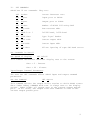
Third is the SOLOS jump table (see next page). All requests to SOLOS
should be made based on this jump table and not to the actual routine
addresses as scattered throughout SOLOS. By using only this jump
table, the user can be assured of maintaining compatibility between
SOLOS and CUTER.
15
V.
SUBROUTINES (cont.)
JUMP TABLE
Function
Address
Label
Length
C000
START
1
This byte allows power-on reset of SOLOS. It
is 00 for SOLOS and 7F for CUTER, providing
an easy means of differentiating the exact
operating system in use.
C001
INIT
3
This is a "JMP" to the power-on reset.
C004
RETRN
3
Enter at this point to return control to
SOLOS command mode processor.
C007
FOPEN
3
Enter here to open a tape file.
C00A
FCLOS
3
Enter here to close a tape file.
C00D
RDBYT
3
Enter here to read a byte from an open tape
file.
C010
WRBYT
3
Enter here to write a byte to an open tape
file.
C013
RDBLK
3
Enter here to read one tape block into memory
based on a header.
C016
WRBLK
3
Enter here to write one tape block from
memory based on a header.
C019
SOUT
3
Enter here to output the character in
register "B" to the current system output
pseudo port. This is always an "LDA"
pointing to the byte containing the current
system output pseudo port value.
C01C
AOUT
3
Enter here to output the character in
register "B" to the pseudo port specified in
register "A".
C01F
SINP
3
Enter here to obtain status/character from
the current system input pseudo port into
register "A". This is always an "LDA" to the
byte containing the current system input
pseudo port value.
C022
AINP
3
Enter here to obtain status/character from
the input pseudo port specified in the "A"
register. On return, register "A" will contain the character with the flags set to
indicate whether a character is present or
not.
16
V.
SUBROUTINES (cont.)
B.
System Entry Points
There are actually only two system entry points within the SOLOS
jump table. Entry at these points does not require that any
register be initialized. The first (at either label "START" or
"INIT") is used to perform a complete power-on system reset. As
a part of the system reset, the system RAM area data used by
SOLOS will be cleared. The only reason for entering via "START"
or "INIT" is that the power-on circuitry requires a one byte
instruction to allow various circuits to stabilize. The other
use of the byte labeled "START" is to determine if a user
program is being executed under SOLOS or is CUTER controlled.
When under SOLOS, this byte will be zero. When under CUTER,
this byte will be non-zero.
The other system entry point ("RETRN") is used to return to
SOLOS command mode. This entry point does not perform a system
reset.
C.
SINP
SOLOS Input Entry Points
entry point address C01F
This entry point will set register "A" to the current system
input pseudo port. The current system input pseudo port is
changed by the "SET I=" command. After setting register "A",
this command proceeds by executing an "AINP". (See below.)
AINP
entry point address C022
This entry point is used to input one character or status from
any pseudo port. Register "A" on entry indicates the desired
input pseudo port from 0 to 3. Because this entry point is a
combination status/get-character routine, it is the user's
responsibility to interpret return flags properly. When a
character is not available, the zero flag will be reset and the
character will be placed into register "A". What this means is
that, if the user wants to wait for a character to be entered,
simply follow the CALL AINP (or SINP) with a "JZ" jump-if-zero
instruction back to the call. A combined status/get-character
routine is very important when allowing user written input
routines.
D.
SOUT
SOLOS Output Entry Points
entry point address C019
This entry point will set register "A" to the current system
out-put pseudo port. The current system output pseudo port is
changed by using the "SET O=" command. After setting register
"A", this command proceeds by executing an "AOUT". (See next
definition.)
17
V.
SUBROUTINES (cont.)
AOUT
entry point address C01C
This entry point is used to output one character to any
pseudo port. Register "A" is assumed to be a binary value
from 0 to 3 indicating the desired output pseudo port.
Register "B" will contain the character to be output. On
return, the PSW and Register "A" are undefined. All other
registers are as they were on entry.
E.
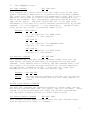
SOLOS VDM Display Driver
Because the VDM is much more powerful than a standard hardcopy
device, the built-in VDM driver supports many expanded functions.
The following characters, when sent to the VDM driver (output
pseudo port 0), cause special functions to be performed:
Hex
Character
Function
01
0B
0D
Control-A
Control-K
Control-M
(SOH)
(VT)
(CR)
13
17
1A
Control-S
Control-W
Control-Z
(DC3)
(ETB)
(SUB)
Move cursor left (wrap mode) one position.
Clear screen; position cursor at home.
Clear remainder of line; then move cursor
to beginning of same line.
Move cursor right (wrap mode) one position.
Move cursor up (wrap mode) one line.
Move cursor down (wrap mode) one line.
The escape key (hex code 1B) is also a special character to the
VDM driver. It initiates what is known as an escape sequence.
The escape character is always followed by one or two hexadecimal values (bytes) which indicate what expanded function is
to be performed. The following lists the escape sequences and
corresponding results. Where a third byte must follow the
escape, this will be represented by (##), indicating that this
third byte actually contains a value being passed to the VDM
driver.
Escape sequence
Function
1B 01 ##
Place the cursor onto position (##) of the current
display line. (##) is in the range 00 - 3F.
1B 02 ##
Place the cursor onto line number (##) of the display screen. (##) is in the range 00 - 0F, with
the topmost line being line 00.
1B 03
Pass back the current cursor line/character position in Registers BC. Register "B" is set to the
character position (00-3F), and Register "C" is
set to the line position (00-0F).
1B 04
Pass back the memory address of the current cursor
location into Registers "BC".
more escape sequences . . .
18
V.
SUBROUTINES (cont.)
Escape sequence
1B 05 ##
1B 06 ##
1B 07 ##
Function
The third byte is output to the VDM at the current
cursor position exactly as is, regardless of this
byte's value. No check is made of this character
(##). Being a control character, it is only
placed into the VDM memory as-is, and the cursor
is advanced one position.
The display speed is set to the value (##)
specified. The speed ranges from 00 (fastest)
to FF (slowest).
1B 09 ##
This functions the same as escape sequence 01.
The cursor is positioned to character position
## of the current display line.
F.
1B 08 ##
Cassette Tape Entry Points to SOLOS
SOLOS contains subroutines to handle data transfer to and from
two cassette units. Both block-by-block and byte-by-byte access
are available. While performing any tape read, the user can
return to the present calling software program by pressing the
MODE (or Control-@) key.
In block transfers, each request results in tape movement and
a transfer of an information block to or from a location in
memory. SOLOS uses block-by-block access to provide the tape
commands.
In byte transfers, on the other hand, SOLOS buffers the data
into 256 byte blocks, doing cassette operations only once per
256 transfers. BASIC uses byte-by-byte access for data files.
Other programs--such as editors, assemblers or special userwritten programs--can also call the byte-by-byte routines if a
few specific conventions and calling sequences are followed.
File Header
The file header for SOLOS provides specific attributes to a
file. These attributes consist of a five ASCII character name
and a file type.
File name serves two functions:
1.
It permits easy human identification of the file, and
2.
It provides the identification for which SOLOS searches
to find the correct file.
File type is used in SOLOS to prevent certain operations, such
as automatic XEQ, if the file is not of the proper type.
19
V.
SUBROUTINES (cont.)
When calling open the register, pair "HL" should point to a
memory location that contains the header. Following is the
layout of a SOLOS file header:
NAME ASC
'12345'
A five character name with trailing binary zeroes.
0
Should always be zero.
TYPE DB
'B'+80H
File type. If Bit 7=1, then this is a data file
(not executable).
SIZE DW
LENGTH
Length of file in number of bytes.
ADDR DW
FROM
Address at which file is to be read to or from
which it is to be written.
XEQ
DW
EXEC
Auto execute address (ignored for data files).
DS
3
Space - not currently used by SOLOS.
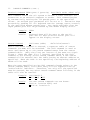
DB
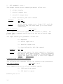
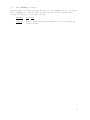
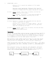
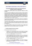
As previously mentioned, SOLOS uses the name to find the correct
data for the file operations. Assume you were about to read data
from a file named POTTS, for example, and you had correctly opened
the file with a header pointing to that name. SOLOS, when you
first requested a data transfer, would read past File 1 and File 2
(as shown below) and then read data from the POTTS file.
Beginning position of tape
(current position)
Beginning of file to be read
Block Access
The Block Access method invokes no management by the system. Each
'call' to the 'Read' or 'Write' routines performs a complete
cassette operation. Read and Write routines are used by SOLOS for
GET and SAVE commands and serve as examples of the calling
conventions for RDBLK and WRBLK routines.
Read Tape Block Routine
RDBLK
The entry point for RDBLK is C013.
On entry:
20
Register A contains Unit and Speed data with bit 5
(speed) 0 for 1200 baud (or 1 for 3$0 baud); bit 7=1
for Tape 1; bit 6=1 for Tape 2; and all other bits=0.
V.
SUBROUTINES (cont.)
Registers H & L contain the address of file header
information.
Registers D & E contain the address-of where the file
is to be loaded into memory. (If set to 0, this information is taken from file header information on tape.)
On exit:
Normal return: Carry Flag is cleared, and data has
been transferred into memory.
Error return:
On errors, or user pressing MODE (or
Control-@) from keyboard, the Carry Flag is set.
Write Tape Block Routine
WRBLK
The entry point for WRBLK is C016.
On entry: Register A contains unit and speed with the same bit
values as specified for RDBLK.
Registers H & L contain file header address. The file
header information will be written onto the specified
tape unit followed by the data.
On exit:
Normal return: Carry Flag is-cleared, and data has been
transferred to tape.
There are no error returns.
Byte Access
Data stored on, or about to be stored on, a tape should be considered
a file. In a SOLOS file, data is stored one byte at a time as a
string of bytes along the tape with no assumed meaning or structure.
It is simply a collection of bytes that can be accessed by someone
with responsibility for the intelligence of the data.
When writing to tape, SOLOS records the data in a form that allows
the data to be read from the tape later. When reading from tape,
SOLOS provides the management to access each byte sequentially.
SOLOS also provides start and stop control of two units. File operations view unit 1 as File 1 and Unit 2 as File 2. Thus, data in Unit
1 is associated with File 1, and data in Unit 2 is associated with
File 2.
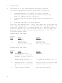
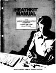
When using Byte Access, two important user management operations
are necessary. As shown in Figure below, the first is to open a
file to tell SOLOS you want to access the file. The second is to
close a file to inform SOLOS you are finished with it.
21
V.
SUBROUTINES (cont.)
SOLOS provides entry points to Open, Read, Write and Close
tape files. Each of these routines requires that certain conventions be followed to ensure accurate data transfers.
File Open Routine
FOPEN
The Open routine sets up certain internal parameters to keep
track of data requests. This operation should be called only
once prior to the first access of the file. The File Header
information is the same format as in the Block Access mode and
is used in both reading and writing of files. If the Byte
Accesses are of the Read type, SOLOS will search the tape file
until the correct file 'name' is found as specified by the File
Header information. On the next Read access, SOLOS will transfer
the first data byte of the file. If the Byte Accesses are of
the Write type, the File Header information will be transferred
onto the file.
The entry point for FOPEN is C007.
On entry: Register A contains File # (1 or 2) same as tape
unit (1 or 2).
Registers H & L contain address of the File Header
information.
On exit:
Normal return: All registers are altered and file
is ready for accesses.
Error return:
The Carry Flag is set.
error: file already open.
Write Byte Routine
Reason for
WRBYT
The Write Byte routine writes a single byte of data into a
buffer file. SOLOS stores this data until it contains 256
bytes. It then writes this block onto the tape, followed by a
CRC character (error checking character). SOLOS then resets
the buffer file for the next 256 bytes of data.
The entry point for WRBYT is C010.
On entry: Register A contains File # (1 or 2).
Register B contains the byte of data to be
transferred onto tape.
On exit:
Normal return: Carry Flag cleared.
Error return: Carry Flag set - errors caused by:
1.
2.
22
file NOT open, or
file previously used for reading.
V.
SUBROUTINES (cont.)
Read Byte Routine
RDBYT
The Read Byte routine reads a single byte of data from a
buffer file. SOLOS fills this buffer as needed per read
request. Each time SOLOS fills the file buffer (reads a
block), the CRC character is checked for data accuracy.
The entry point for RDBYT is C00D.
On entry:
Register contains file # (1 or 2)
On exit:
Normal return: Register A contains data byte.
Carry and Minus Flags set mean 'end of file'.
Error return:
by:
1.
2.
3.
4.
Carry Flag set. Errors are caused
file NOT open
file previously used for writing
CRC character error
pressing MODE (or Control-@) while
actually reading from the tape.
Close File Routine FCLOS
The Close file routine closes the current file and resets the
internal parameters for the next open operation. It is very
important to close the file after all data transfers are
completed. Failure to do so could result in lost data and
prevent further open operations.
The entry point for FCLOS is C00A.
On entry:
Register A contains File # (1 or 2) to be
closed.
On exit:
Normal return: Carry Flag cleared.
Error return: Carry Flag set. (Error is caused
by file NOT open.)
23
VI.
LOADING & EXECUTING CUTER
(Applicable to CUTER only)
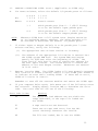
CUTER is available (1) on cassette tape with its own loader which
can be loaded at any memory address from 0200 through F400, or (2)
in ROM at the address C000. In order to load CUTER from cassette
tape, perform the following steps. When CUTER is being used in
ROM, the procedure is much simpler: make sure the sense switches
are set according to H below prior to executing location C000.
A.
Verify that the hardware is connected and functioning
properly.
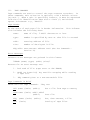
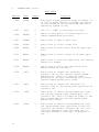
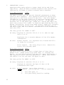
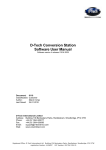
B.
Enter the following bootstrap routine into memory beginning
at location 0. The following is presented in a format
similar to that produced by a "DUMP" command with an address
shown every 10 (hex) bytes:
0000: 21 40 00 F9
0010: 3D C2 0F 00
0020: DB FA A5 CA
45 4D 3E 80
E7 02 03 FE
20 00 DB FB
D3 FA E7 05
DD C2 14 00
C9
C2 0A 00 E7
E9 00 00 00
C.
Verify that the above bootstrap is in memory exactly as presented.
D.
Set the sense switches to the address at which CUTER is to be
loaded. The sense switches will be the hi-order byte of the
memory address, with the lo-order byte zero. As an example:
Sense switches set to 34 hex will cause CUTER to be loaded
into memory beginning at location 3400 hex. For convenience,
a memory address should be selected that also specifies the
default I/O pseudo ports (see "H" below). The address
specified must be between 0200 and F400. Remember, however,
that CUTER occupies 2K of memory and uses 1K of RAM beyond
that.
E.
Make sure that the CUTER tape is rewound and placed into the
proper cassette machine. The CUTER bootstrap will activate
the motor control for tape unit one. If your cassette
machine motor control is attached as tape unit one, you may
now place the machine into "PLAY" mode.
F.
Execute location zero (the bootstrap). This can be
accomplished by allowing a "Reset" to specify an address of
zero. At this time, be certain that the cassette machine is
in "PLAY" mode and is activated:
G.
When completed, the CUTER loader program will "HALT". This
is not an error condition. When completed, the motor control
will also be turned off.
24
VI.
LOADING & EXECUTING CUTER (cont.) (Applicable to CUTER only)
H.
Via sense switches, select the default I/O pseudo ports as follows:
Bit
X X X X
7 6 5 4
I I O O
3 2 1 0
Where:
X X X X
doesn't matter
I I
which pseudo port from 0 - 3 (00-11 binary)
is to be the default input pseudo port.
O O
which pseudo port from 0 - 3 (00-11 binary)
is to be the default Output pseudo port.
NOTE:
I.
If either Input or Output default is to be pseudo port 3 (user
written routine), verify the following:
(i)
(ii)
J.
Whenever CUTER does a full system reset (begins execution
at its beginning memory address), the sense switches will
be accessed to determine the default I/O pseudo ports.
The appropriate user written routine is in memory.
The address of the appropriate I/O routine is entered into
the CUTER system RAM area. The system RAM area begins
exactly 2K (800 hex) after the beginning of CUTER. The
first word of this area is used to contain the address for
the user Input routine. The second word will contain the
address of the user Output routine. Addresses are entered
in lo-hi order.
Execute location ZERO. The CUTER loader will have properly prepared
this location to either transfer control to the CUTER just loaded or
to indicate an error while loading CUTER. If there was no error,
CUTER will now be in control.
Remember to turn off the cassette machine and remove the CUTER tape.
K.
IF your computer halts again, this means one of the following errors
has occurred. Display memory location ONE to determine the error
code. The error code will be one of the following:
Error Code in Hex
Meaning
00
The specified load address was not within the
range 0200-F400, or the tape file loaded was
not CUTER.
01
A tape read error was detected.
02
There was no tape read error, but the CRC
(error checking) character was invalid.
40
The file was loaded, but it was not CUTER.
25