1
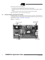
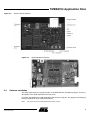
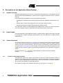
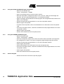
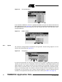
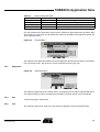
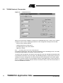
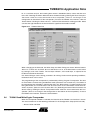
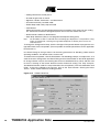
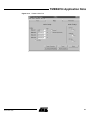
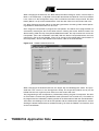
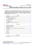
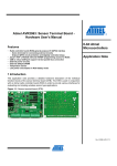
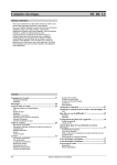
RFID Application Kit TMEB8704
1. Introduction
The RFID application kit TMEB8704 is designed to demonstrate the key features of
Atmel’s various RFID products. The included software version IDS 5 supports the following products:
TMEB8704
RFID
Application Kit
• U2270B on the reader side
• TK5530/e5530 on the transponder side
• TK5551/e5551 on the transponder side
Application Note
• TK5552 on the transponder side
• TK5561/e5561 on the transponder side
• U9280M on the transponder side
2. Getting Started
For proper operation of the demonstration system, the following requirements must be
met.
2.1
Minimum System Requirements
• Pentium® processor-based PC
• 16 MB RAM memory
• Windows® 95 or higher
• CD-ROM drive
• VGA monitor
• RS232 serial interface (COM1 or COM2)
• Mouse
2.2
Hardware Requirements and Installation
• Microcontroller board 1.0 with application kit 5
• R/W antenna 100 mm∅/L = 700 µH/Q = 36
• RS232 serial communication cable
• Power source 12V (AC/DC)/200 mA
• Jack connector cable for power supply
Rev. 4781A–RFID–10/05
Before getting started, check the following:
• The antenna must be plugged into the socket of the interface board
• The RS232 connector on the interface board must be connected to either COM1 or COM2 of
the PC
• A supply line from the power source to the jack connector must be available
When all 3 conditions are met, set the power switch to ON.
2.3
Hardware Settings and Connector Positions
In RFID applications, the main board with the microcontroller is operated in a fixed configuration;
no settings are necessary. Check jumper J3 on the antenna interface to verify that it is has the
default setting (see Figure 2-1 and Figure 2-2 on page 3).
Figure 2-1.
Main Board
RS 232 Connector
Reset Button
2
Jack Connector
Power Supply
Power Switch
TMEB8704 Application Note
4781A–RFID–10/05
TMEB8704 Application Note
Figure 2-2.
Antenna Interface Board
Figure 2-3.
2.4
Application Board Topview
Software Installation
The RFID application kit package includes a CD-ROM with the installation program, and has a
description of the RFID application kit on the cover.
Insert the CD-ROM into the CD-ROM drive and execute setup.exe. The program (including all
libraries needed) will be installed automatically.
Note:
It is necessary to have write permission for the system.
3
4781A–RFID–10/05
3. Description of the Application Board System
3.1
System Overview
The RFID application board consists of a standard microcontroller board 1.0 (equipped with the
Atmel microcontroller AT90S8515), combined with a piggybacked board serving as antenna
interface.
The microcontroller AT90S8515 carries out the following functions:
• Handling the bi-directional data communication between the application board and the host
PC
• Executing the read and write commands to be sent to the antenna interface
• Decoding the specific read data delivered by the antenna interface
The application software is downloaded into the 8 KByte Flash memory of the microcontroller.
The current program version is indicated on the label attached to the main board.
3.2
Power Supply
For proper operation of the application board, an external power supply in the range of DC 10V
to 15V/200 mA is required. A bridge rectifier placed at the connector input is used for polarity
independence.
3.3
Antenna Interface
The antenna interface (see Figure 2-2 on page 3) is connected via the header connector located
on the main board. The LED Power indicates the actual supply voltage. To adapt a specific
antenna coil to the resonant frequency and the Q-factor, the components CANT1/CANT2 and
R14 (see Figure 2-2 on page 3) can be changed. The matching of the interface depends on the
added coil. The parameters and the corresponding components for the adjustment are given as
follows:
Resonant frequency: fres = 125 kHz by CANT1/CANT2 at Jumper 3 to position Disable
Q-factor:
Q = 20 by R14
3.3.1
Frequency Tuning Mode Selection
The application system has a built-in tuning feature to match the resonant frequency of the LC
antenna circuit automatically to the frequency of a specific transponder. The board is equipped
with two stages of high-voltage transistor switches to tune the resonator by switched capacitors.
This increases the reliability and operating distance.
The frequency tuning can be selected using jumper J3 (see Figure 2-2 on page 3).
4
TMEB8704 Application Note
4781A–RFID–10/05
TMEB8704 Application Note
Table 3-1.
Tuning Mode Selection
Tuning Mode
Jumper J3 Position
Disabled
1–2
Enabled
2–3
When tuning mode is disabled, the RFID application kit operates with a fixed frequency,
adjusted nominally to 125 kHz. To control the tuning, the tuning mode has to be enabled by the
RFID application program. The binary combination of two tuning stages enables the selection of
one out of four frequency states. The frequency range is extended typically from 122 kHz to
128 kHz in steps of 2 kHz (specified in the program menu by Low Frequency, Semi Low Frequency, Semi High Frequency and High Frequency).
The currently selected frequency stage is indicated in binary mode on the application board by
the red LEDs Tune 1 and Tune 2 (see Figure 2-2 on page 3).
3.3.2
RF Field Control
The status of the RF field controlled by the microcontroller is indicated by the yellow LED RF On.
5
4781A–RFID–10/05
6
X2/9
X2/10
X1/11
X1/7
X1/3
X2/5
X1/6
X2/1
M2
DZ1
LD1
Power
R1
1 kΩ
Green
IN
R2
360Ω
M12
Data in
Data out
M11
10 µF
C3
M1
VCC
LD4
RFon
R7
150Ω
7808
U2
Yellow
OUT
M4
6
16
7
1
3
2
13
12
10
11
R3
10 kΩ
220 nF
C6
C5
VS
14
R15
220Ω
LD2
TUNE1
CFE
HIPASS
DGND
GND
OE
OUTPUT
STANDBY
VBATT
VEXT
DVS
MS
5
68 kΩ
Red
R17
1.5 kΩ
R16
3.6 kΩ
COIL1
COIL2
INPUT
RF
15
R9
43 kΩ
C7
9
8
BF820
T1
R18
100Ω
100 pF
BAS21
D3
D2
BAS21
CANT1
150 pF
24Ω
R14
LD3
TUNE2
BAS21
D6
R19
220Ω
Red
R21
1.5 kΩ
R20
3.6 kΩ
BF820
T2
R22
100Ω
1
Antenna
BAS21
D7
180 pF
2
X3
CTUNE2
L1
M14
L2
M13
Components
for feedback
application
4.7 nF
C9
1 2 3
J3
2.2 nF
CANT1
BAS21
D5
100 kΩ
R13
75 kΩ
R12
D4
BAS21
Components for tuning application
R11
470 kΩ
R10
4.7 kΩ
BAV21
CTUNE1
2.2 nF
C7
6.8 nF
4
M15
D1
Figure 3-1.
22 µF
R8
3.3.3
Circuit Diagram of the Antenna Interface
Circuit Diagram of the Antenna Interface
TMEB8704 Application Note
4781A–RFID–10/05
TMEB8704 Application Note
3.3.4
Parts List of the Antenna Interface
U1
=
U2
=
U2270B
LM7808
SO16
TO220
=
=
=
=
=
=
=
=
BAS21
BAS21
BAS21
BAS21
BAS21
BAS21
BAS21
BZX84C
SOT23
SOT23
SOT23
SOT23
SOT23
SOT23
SOT23
5.6V, SOT23
=
=
=
=
TLMC3100 (green)
TLMT3100 (red)
TLMT3100 (red)
TLMA3100 (yellow)
PLCC2
PLCC2
PLCC2
PLCC2
=
=
BF820
BF820
SOT23
SOT23
=
=
=
=
=
=
=
=
=
=
=
=
=
=
=
=
=
=
=
3.6 kΩ
360Ω
10 kΩ
1 kΩ
68 kΩ
43 kΩ
4.7 kΩ
470 kΩ
75 kΩ
100 kΩ
24Ω
1 kΩ
3.6 kΩ
1.5 kΩ
100Ω
1 kΩ
3.6 kΩ
1.5 kΩ
100 Ω
0805
0805
0805
0805
0805
0805
0805
0805
0805
0805
0805
0805
0805
0805
0805
0805
0805
0805
0805
Diodes:
D1
D2
D3
D4
D5
D6
D7
DZ1
LEDs:
LD1
LD2
LD3
LD4
Transistors:
T1
T2
Resistors:
R1
R2
R3
R7
R8
R9
R10
R11
R12
R13
R14
R15
R16
R17
R18
R19
R20
R21
R22
7
4781A–RFID–10/05
Capacitors:
CANT1
CANT2
CTUNE1
CTUNE2
C3
C4
C5
C6
C7
C8
C9
=
=
=
=
=
=
=
=
=
=
=
2.2 nF (5%)
150 pF
100 pF
180 pF
10 µF/16V
22 µF/16V
22 µF/16V
220 nF
22 nF
2.2 nF
4.7 nF
0805
0805
0805
0805
0805
0805
Miscellaneous:
• SUB-D 9-pole socket
• 3-pole connector for coil
• Gold-pin block for jumper (1 x 3 pole)
• 2 gold-pin block 1 x 18 pole (used for header connector to the main board)
The antenna coil included in the IDIC application kit measures the following parameters related
to 125 kHz:
8
Inductance
L = 700 µH
Coil diameter
d = 100 mm
Winding number
n = 60
Wire diameter
dw = 0.25 mm
TMEB8704 Application Note
4781A–RFID–10/05
TMEB8704 Application Note
4. Identification Application Software IDS 5
4.1
Getting Started
• Read this RFID Application Kit user's manual.
• Install the IDS 5 software.
• Connect an RS232 serial cable between the RFID application kit and the PC.
• Connect a 12V (AC or DC) power supply to the RFID application kit (using the jack
connector). The status Power on is indicated by a green LED near the microcontroller.
• Start the program RFID Application Software.
• Select the COM port to be used in the Setup menu.
4.1.1
Using the TK5530 Read-only Transponder
• Select the transponder type
Setup -> Transponder -> TK5530
• Place a transponder close to the base-station antenna
• Enter the transponder's configuration details such as bit rate, coding, ID-code length,
signature and header. (For non-specialized applications, use the default settings.)
• Click Read to show the transponder code
4.1.2
Using the TK5551 Read/Write Transponder
• Select the transponder type
Setup -> Transponder -> TK5551
• Place a transponder close to the base-station antenna
• Enter the transponder's configuration details such as bit rate, coding, ID-code length and
signature. (For non-specialized applications, use the default settings.)
• Click on Configure Transponder (this function programs the configuration block, Block 0, of
the TK5551)
• Choose the Write tab to program Blocks 1 to 7 of the transponder memory
• Select Program Transponder
• To read out the transponder, click the Read button in the Read tab to show the transponder
code
4.1.3
Using the TK5552 Read/Write Transponder
• Select the transponder type
Setup -> Transponder -> TK5552
• Place a transponder close to the base-station antenna
• Enter the transponder's configuration details such as bit rate, coding, ID-code length and
signature. (For non-specialized applications, use the default settings.)
• Click on Configure Transponder (this function programs the configuration block, Block 0, of
the TK5552)
• Choose the Write tab to program Blocks 1 to 31 of the transponder memory
• Select Program Transponder
• To read out the transponder, click the Read button in the Read tab to show the transponder
code
9
4781A–RFID–10/05
4.1.4
Using the TK5561 Read/Write/Crypto Transponder
• Select the transponder type
Setup -> Transponder -> TK5561
• Place a transponder close to the base-station antenna
• Enter the transponder's configuration details such as bit rate, coding, ID-code length and
signature. (For non-specialized applications, use the default settings.)
• Click on Configure Transponder (this function programs the configuration blocks, Block 0 and
Block 9, of the TK5561)
• Choose the Write tab to program Blocks 1 to 4 of the transponder memory
• Select Program Transponder
• To read out the transponder, click on the Read button in the Read tab to show transponder
code
• To start the encryption process, choose the Authentication tab to program Blocks 5 to 8 of the
transponder memory
• Select Program Transponder
• Choose Start Authentication for encryption process
4.1.5
Using the U9280M Read/Write/Crypto
• Select transponder type
Setup -> Transponder -> U9280M
• Place the transponder sample close to the base-station antenna (consider axial alignment)
• The configuration is fixed; it can only be changed by programming through the interface
• Choose the Write tab to program Blocks 1 to 4 of the transponder memory
• Click Program Transponder
• Click the Read button in the Read tab to show the transponder code
• To start the encryption process, choose the Authentication tab to program Blocks 5 to 8 of the
transponder memory
• Click Program Transponder
• Click Start Authentication for encryption process
4.1.6
Exit the Program
• Choose Exit from the main menu to quit the program
10
TMEB8704 Application Note
4781A–RFID–10/05
TMEB8704 Application Note
5. Description of the RFID Application Kit Software IDS 5
Figure 5-1.
5.1
RFID Application Kit 5 Software
Software Structure
The included software supports the following Atmel transponder types:
• TK5530 Read-only
• TK5551 Read/Write
• TK5552 Read/Write (1 kbit)
• TK5561 Read/Write/Crypto
• U9280M Read/Write/Crypto
All transponder types and their particular features and functions can be controlled by one program; the software automatically selects the features supported depending on the transponder
type used. The software is developed for the use of different transponders and their features.
This means the user does not need to worry about the technical details.
5.2
Start Window
The menu bar of the application software contains five menus. These are: Setup, Option, Application, Exit, Info.
5.2.1
Setup
When the submenu Transponder in the Setup menu is selected, the different types of Atmel’s
transponders can be seen (see Figure 5-2 on page 12). Depending on the transponder chosen,
the user interface will be adjusted.
11
4781A–RFID–10/05
Figure 5-2.
Transponder Menu
In the submenu COM-Port, select the appropriate RS232 serial port to communicate with the
RFID application kit (see Figure 5-3). (To verify that there is communication between the PC and
the application board, press function key F12 and all LEDs will flash; if the LEDs don’t flash,
change COM-Port.)
Figure 5-3.
5.2.2
COM-Port Menu
Option
The submenu Tuning enables two different tuning modes: manual tuning (High to Low Frequency) and Autotuning (see Figure 5-4).
Figure 5-4.
Tuning Menu
In manual tuning mode, the user can select one of four frequency stages from 122 kHz to
128 kHz in steps of 2 kHz (Low Frequency, Semi Low Frequency, Semi High Frequency and
High Frequency). This requires that the on-chip oscillator of the U2270B is tuned to 125 kHz
(these values are nominal values, the actual values may differ slightly due to component tolerances). In autotuning mode, the software switches between the four frequencies until the
transponder can be read out. The currently selected frequency stage is indicated, binary
encoded, on the application board by the Tune 1/Tune 2 LEDs (see Table 5-1 on page 13).
12
TMEB8704 Application Note
4781A–RFID–10/05
TMEB8704 Application Note
Table 5-1.
Binary Tuning LED Code
Tune 2
Tune 1
Frequency
0
0
High
0
1
Semi-high
1
0
Semi-low (default)
1
1
Low
Use the submenu item RF-Field to switch the RF field on the RFID application kit ON or OFF
(see Figure 5-5). The status is indicated by the yellow RF On LED on the application board. RF
On is the default value.
Figure 5-5.
RF-Field Menu
The submenu item Demoboard Reset resets the application board and all changes in the Option
menu to default values. The reset can also be selected by pressing key F12.
5.2.3
Application
Figure 5-6.
Application Menu
The submenu Application is for advanced users and enables them to find the optimal adjustment
of the Write Timing, as well as providing the possibility to write bit strings to the transponder.
5.2.4
Exit
To exit the program, choose Exit.
5.2.5
Info
The submenu About in the main menu Info shows the program version and creation date.
13
4781A–RFID–10/05
5.3
TK5530 Read-only Transponder
Figure 5-7.
TK5530 Read Tab
When the transponder TK5530 is selected, the TK5530 Read tab is shown. This window
enables the user to set the following parameters in the Configuration Setup (on the left side):
• Bit rate: Rf/32, Rf/40 and Rf/64
• Coding: Manchester and Bi-phase
• ID-code length: 32, 64, 96 and 128 bit
• Signature: Header
Note:
For details, please refer to the e5530 datasheet.
Using Read Timing on the right side, the timing parameters for the decoding can be set. Under
normal operating conditions, the default values can be used.
To read out the transponder, click Read. A message box shows the decoded transponder code
in hexadecimal characters or an error report. The decoding principle, in simple terms, consists of
sending the chosen Configuration and Read Timing to the microcontroller on the RFID application kit. In a real-time analysis, the incoming data stream is decoded to binary values and sent to
the PC. Clicking on the button Default restores the default setting. Click the Cancel button to
leave the TK5530 user interface.
14
TMEB8704 Application Note
4781A–RFID–10/05
TMEB8704 Application Note
5.4
TK5551 Read/Write Transponder
Figure 5-8.
TK5551 Read Tab
When the transponder TK5551 is selected, the Read tab of the TK5551 user interface is shown.
This window enables setting the following parameters in the Configuration Setup (on the left
side):
• Bit rate: Rf/8, Rf/16, Rf/32, Rf/40, Rf/50, Rf/64, Rf/100 and Rf/128
• Coding: Manchester, Bi-phase, direct, PSK, FSK, (see e5551 datasheet)
• ID-code length: Block 0, Block 1, Block 1 to 2, Block 1 to 3, Block 1 to 7
• Signature: Header, sequence terminator, block terminator, and block and sequence
terminator
• Password: Activates password mode
• Lock Block 0: Setting this bit locks the configuration block of the transponder. That means bit
rate, coding, etc. are fixed and cannot be changed anymore. Please use this feature with care
• Stop-mode enable: obey stop command
• Answer-On-Request: Activates anticollision mode (ticking shows an additional button for
AOR wake-up)
Note:
The U2270B is not able to read all displayed bit rates and coding types. If invalid settings are
selected, a warning message will be displayed. For details, please refer to the e5551 datasheet.
To change the Configuration Setup, click the Configure Transponder button to program the configuration block of the transponder. (The transponder should be placed close to the RFID
application kit antenna.)
Read Timing on the right side enables the setting of the timing parameters for decoding. Under
normal operating conditions, the default values can be used.
15
4781A–RFID–10/05
To read out the transponder, click Read. The decoding principle, in simple terms, is to send the
chosen Configuration and Read Timing to the microcontroller on the RFID application kit. In a
real-time analysis, the incoming data stream is decoded to binary values and then sent to the
PC. Clicking the button Default restores the default setting. Clicking the Stop Transponder-Modulation button sends the stop command to the transponder. (This disables modulation until the
transponder receives a POR or AOR wake-up command.) To leave the TK5551 user interface,
click Cancel. Click Direct Access..., to do blockwise reading. Make sure that the right Header for
the chosen block is typed into the header text field. If Sequence Terminator is activated, only
Block 0 and the Maxblock are readable (for example, Block 1 to 5 is configured, then Block 5 is
also readable with Direct Access....).
Figure 5-9.
TK5551 Write Tab
When the Write tab is selected, the Write Setup and Write Timing are shown. The first byte in
Block 1, the header byte, is adjusted in the header text field of the Read tab. The password box
is the same as in the configuration setup. When the Password box is selected, Block 7 changes
to password.
Use Write Timing on the right side to set the timing parameters for writing. Under normal operating conditions, the default values can be used.
The programming of the transponder is performed by clicking Program Transponder. The data
for each block is entered using hexadecimal code (characters 0 to 9 and A to F). The blocks to
be programmed are selected by selecting the corresponding check box in the Write column. To
protect the data from being overwritten, the lock bit feature can be used. Once set, the information cannot be overwritten. (Please use this feature with care.) Default restores the default
setting. To leave the TK5551 user interface, click Cancel.
16
TMEB8704 Application Note
4781A–RFID–10/05
TMEB8704 Application Note
5.4.1
Answer-On-Request (AOR)
This feature is used to address an individual transponder when several transponders are in the
field. A transponder with activated AOR feature remains silent (no modulation) when an RF field
is applied. When the AOR wake-up sequence has been transmitted, the transponder starts
transmitting in ID mode and remains active until a POR occurs or a stop command is sent. A
transponder that has been activated by an AOR sequence operates like a transponder in standard read mode. The AOR feature is only useful in combination with the password mode.
Without a password, all transponders start modulation after each AOR wake-up sequence.
Warning:
Once the transponder has been configured to AOR mode, the user needs to know the correct
AOR wake-up sequence (password/Block 7) to read out the transponder's code. To change the
transponder's configuration (for example, to deactivate AOR mode), the password is also
required. During system design, use this feature with care.
To configure AOR mode, follow the steps below:
1. Activate Password and Answer-On-Request in the Configuration Setup of the Read tab
2. Type in a unique password (hexadecimal code) into the Password text field
3. Change to the Write tab, select the Password check box in the Write Setup column and
click on the Program Transponder button
4. Then click on Configure Transponder in the Read tab
5. The transponder is now in AOR and password mode
This way, each transponder can be set to AOR mode. When all transponders are configured, put
them into the RF field. To read out the transponders, follow the steps below.
1. Type the password for a specific transponder into the Password text field
2. Click on the AOR wake-up button to activate the specific transponder
3. Read out the transponder by clicking Read
4. To stop the read function, click Stop Transponder-Modulation
5. Repeat steps 1 to 4 for the next transponder, using the appropriate password
17
4781A–RFID–10/05
5.5
TK5552 Read/Write Transponder
Figure 5-10. TK5552 Read Tab
When the transponder TK5552 is selected, the Read tab of the TK5552 user interface is shown.
This page enables setting the following parameters in the Configuration Setup (on the left side):
• Bit rate: Rf/16 and Rf/32
• Coding: Manchester and PSK
• ID-code length: Block 0, Block 1, Block 1 to 2, Block 1 to 3,...,Block 1 to 31
• Signature: Header
• Lock Block 0:
Setting this bit locks the configuration block of the transponder. This means bit rate, coding,
etc. are fixed and cannot be changed anymore. Please use this feature with care
• Start-up delay: No (only POR) or POR and additional 8192 clocks of the RF-field
• Modulation defeat:
When Mod. off is activated, no data will be transmitted. It will appear as if no transponder is in
the RF field
Note:
The U2270B is not able to read all bit rates and coding types displayed. If invalid settings have
been selected, a warning message will be displayed. For details, please refer to the e5552
datasheet in the TK5552 appendix.
To change the Configuration Setup, click the Configure Transponder button to program the configuration block of the transponder. (The transponder should be placed close to the application
board antenna.)
Click Read Timing on the right side to set the timing parameters for decoding. Under normal
operating conditions, the default values can be used.
To read out the transponder, use the Read button. The decoding principle, in simple terms, is to
send the chosen Configuration and Read Timing to the microcontroller on the RFID application
18
TMEB8704 Application Note
4781A–RFID–10/05
TMEB8704 Application Note
kit. In a real-time analysis, the incoming data stream is decoded to binary values and then sent
to the PC. Choosing the button Default restores the default setting. Clicking the Reset Transponder button sends the reset command to the transponder. (There is no change in the
configuration or data blocks of the transponder.) To leave the TK5552 user interface, click the
Cancel button. Clicking the Direct Access... button makes blockwise reading possible. Make
sure that the right Header for the chosen block is typed into the header text field.
Figure 5-11. TK5552 Write Tab
When changing to the Write tab, the Write Setup and Write Timing are shown. With the buttons
Block 1 to 7, Block 8 to 15, Block 16 to 23 and Block 24 to 31, all 31 data blocks can be shown
by packages, each with 7 blocks. The first byte in Block 1, the header byte, is adjusted in the
header text field of the Read tab.
Use Write Timing to set the timing parameters for writing. Under normal operating conditions,
the default values can be used.
The programming of the transponder is performed by clicking Program Transponder. The data
for each block is entered using hexadecimal code (characters 0 to 9 and A to F). The blocks to
be programmed are selected by selecting the box in the Write column. To protect the data from
being overwritten, the Lock bit feature can be used. Once set, the information cannot be overwritten anymore. (Please use this feature with care.) Selecting the button Default restores the
default setting. Clicking the Reset Transponder button sends the reset command to the transponder. (There is no change in the configuration or data blocks of the transponder.) To leave
the TK5552 user interface, click on the Cancel button.
5.6
TK5561 Read/Write/Crypto Transponder
When the transponder TK5561 is selected, the Read tab of the TK5561 user interface is shown.
This sheet enables to set the following parameters in the Configuration Setup (on the left side):
• Bit rate: Rf/32 and Rf/64
19
4781A–RFID–10/05
• Coding: Manchester and Bi-phase
• ID-code length: 64 bit or 128 bit
• Signature: Header, Terminator 1 and Terminator 2
• Password: Activates password mode
• Enable Stop-mode: Obey stop command
• Lock Block 0:
Setting this bit locks the configuration block of the transponder. This means bit rate, coding,
etc. are fixed and cannot be changed anymore. Please use this feature with care.
• AUT64 rounds: Number of AUT64-times
• Auto adapt: Automatic (ON) or user-programmed adapt bit setting (OFF)
Note:
The U2270B is not able to read all bit rates and coding types displayed. If a transponder is configured in an invalid mode, a warning message will be displayed. For details, please refer to the
e5561 datasheet.
To change the Configuration Setup, click the Configure Transponder button to program the configuration block of the transponder. (The transponder should be placed close to the application
board antenna.)
Use Read Timing on the right side to set the timing parameters for decoding. Under normal
operating conditions, the default values can be used.
To read out the transponder, click the Read button. The decoding principle, in simple terms, is to
send the chosen Configuration and Read Timing to the microcontroller on the RFID application
kit. Using real-time analysis, the incoming data stream is decoded to binary values and then sent
to the PC. Clicking on the button Default restores the default setting. The Stop Transponder-Modulation button sends the stop command to the transponder. (This halts modulation until
POR.) To leave the TK5561 user interface, click on the Cancel button. Clicking the Direct
Access... button makes blockwise reading possible.
Figure 5-12. TK5561 Read Tab
20
TMEB8704 Application Note
4781A–RFID–10/05
TMEB8704 Application Note
Figure 5-13. TK5561 Write Tab
21
4781A–RFID–10/05
When changing to the Write tab, the Write Setup and Write Timing are shown. The first byte in
Block 1, the header byte, is adjusted in the header text field of the Read tab. The Password box
is the same as in the configuration setup. The Lock Block 9 box locks the password. The data
blocks (Blocks 1 to 4) can be locked with the Lock data box. Please use this feature with care.
Use Write Timing on the right side to set the timing parameters for writing. Under normal operating conditions, the default values can be used.
Click Program Transponder to program the transponder. The blocks to be programmed are
selected by selecting the box in the Write column. Clicking the button Default restores the
default setting. With the Stop Transponder-Modulation button, the stop command is sent to the
transponder. (This halts modulation until POR.) With the Reset Transponder button, the reset
command is sent to the transponder. (There is no change in the configuration or data blocks of
the transponder.) To leave the TK5561 user interface, click on the Cancel button.
Figure 5-14. TK5561 Authentication Tab
When changing to the Authentication tab, the Crypto Key and Challenge are shown. The password box is the same as in the Configuration Setup. The Crypto Key (Blocks 5 to 8) can be
locked with the Lock crypto keys box. Please use this feature with care.
The programming of the transponder is performed by clicking Program Transponder. The data
for each block is entered using hexadecimal code (characters 0 to 9 and A to F). The blocks to
be programmed are selected by selecting the box in the Write column. With the Start Authentication button, the challenge is sent to the transponder and the authentication procedure is started.
Clicking the button Default restores the default setting. To leave the TK5561 user interface, click
on the Cancel button.
22
TMEB8704 Application Note
4781A–RFID–10/05
TMEB8704 Application Note
5.6.1
Authentication
The RFID application kit can be used to demonstrate the encryption feature of the TK5561
read/write/crypto transponder. The PC software provides a user interface that enables the configuration of the transponder. Furthermore, the RFID application kit acts as a base station so a
real challenge/response authentication procedure can be carried out. The AUT64 encryption
algorithm used in the transponder is fully emulated by the microcontroller of the RFID application
kit. The algorithm is carried out by hardware in the transponder and by the microcontroller. Both
results are displayed on the PC and authentication is verified. The user can change the input
parameters and key data of the encryption algorithm.
5.7
U9280M Microcontroller with Transponder Interface
The transponder board is equipped with a standard U9280M-036 ROM mask version.
The U9280M-036 emulates the basic functions of the RFID transponder TK5561 combined with
keyless entry functionality.
When the transponder U9280M is selected, the Read tab is displayed. This sheet shows the
parameters of the Fixed Configuration (on the left side):
• Bit rate: Rf/32
• Coding: Manchester
• ID-code length: 128 bit
• Signature: Terminator 1
• AUT64 rounds: 24 times
This configuration cannot be changed by a base station set up command. Parameters can be
changed by executing a special interface programming.
Use Read Timing on the right side to set the timing parameters for decoding. Under normal
operating conditions, the default values can be used.
To read out the transponder, use the Read button. The decoding principle, in simple terms, is to
send the Fixed Configuration and Read Timing to the microcontroller on the RFID application kit.
In a real-time analysis, the incoming data stream is decoded to binary values and then sent to
the PC. Clicking on the button Default restores the default setting. Clicking the Stop Transponder-Modulation button sends the stop command to the transponder (this halts modulation until
POR). To leave the U9280M user interface, click on the Cancel button.
23
4781A–RFID–10/05
Figure 5-15. U9280M Read Tab
Figure 5-16. U9280M Write Tab
24
TMEB8704 Application Note
4781A–RFID–10/05
TMEB8704 Application Note
When changing to the Write tab, the Write Setup and Write Timing are shown.
Use Write Timing on the right side to set the timing parameters for writing. Under normal operating conditions, the default values can be used.
The programming of the transponder is performed by the Program Transponder button.
The blocks to be programmed are selected by selecting the box in the Write column.
Clicking the button Default restores the default setting.
With the Stop Transponder-Modulation button, the stop command is sent to the transponder
(this halts modulation until POR).
To leave the U9280M user interface, click on the Cancel button.
Figure 5-17. U9280M Authentication Tab
5.7.1
Authentication
The RFID application kit can be used to demonstrate the encryption feature of the U9280M
read/write/crypto transponder. The PC-based software provides a user interface that enables
the configuration of the transponder. Furthermore, because the RFID application kit acts as a
base station, a real challenge/response authentication procedure can be carried out. The AUT64
encryption algorithm used in the U29280M is implemented as a part of the mask programming.
The algorithm is started by the button Start Authentication. The checksum result and encryption
response of the AUT64 are displayed in separate messages for the transponder and base station. If both responses are equal, the AUT64 result displays OKAY; if unequal, the AUT64 result
displays Error AUT64.
The user can change the input parameters and key data of the encryption algorithm.
Note:
Remark: Data value in block 6 is restricted: The 3 LSB of each nibble must be different.
25
4781A–RFID–10/05
Figure 5-18. Message Box AUT64 Result
26
TMEB8704 Application Note
4781A–RFID–10/05
Atmel Corporation
2325 Orchard Parkway
San Jose, CA 95131, USA
Tel: 1(408) 441-0311
Fax: 1(408) 487-2600
Regional Headquarters
Europe
Atmel Sarl
Route des Arsenaux 41
Case Postale 80
CH-1705 Fribourg
Switzerland
Tel: (41) 26-426-5555
Fax: (41) 26-426-5500
Asia
Room 1219
Chinachem Golden Plaza
77 Mody Road Tsimshatsui
East Kowloon
Hong Kong
Tel: (852) 2721-9778
Fax: (852) 2722-1369
Japan
9F, Tonetsu Shinkawa Bldg.
1-24-8 Shinkawa
Chuo-ku, Tokyo 104-0033
Japan
Tel: (81) 3-3523-3551
Fax: (81) 3-3523-7581
Atmel Operations
Memory
2325 Orchard Parkway
San Jose, CA 95131, USA
Tel: 1(408) 441-0311
Fax: 1(408) 436-4314
RF/Automotive
Theresienstrasse 2
Postfach 3535
74025 Heilbronn, Germany
Tel: (49) 71-31-67-0
Fax: (49) 71-31-67-2340
Microcontrollers
2325 Orchard Parkway
San Jose, CA 95131, USA
Tel: 1(408) 441-0311
Fax: 1(408) 436-4314
La Chantrerie
BP 70602
44306 Nantes Cedex 3, France
Tel: (33) 2-40-18-18-18
Fax: (33) 2-40-18-19-60
ASIC/ASSP/Smart Cards
1150 East Cheyenne Mtn. Blvd.
Colorado Springs, CO 80906, USA
Tel: 1(719) 576-3300
Fax: 1(719) 540-1759
Biometrics/Imaging/Hi-Rel MPU/
High Speed Converters/RF Datacom
Avenue de Rochepleine
BP 123
38521 Saint-Egreve Cedex, France
Tel: (33) 4-76-58-30-00
Fax: (33) 4-76-58-34-80
Zone Industrielle
13106 Rousset Cedex, France
Tel: (33) 4-42-53-60-00
Fax: (33) 4-42-53-60-01
1150 East Cheyenne Mtn. Blvd.
Colorado Springs, CO 80906, USA
Tel: 1(719) 576-3300
Fax: 1(719) 540-1759
Scottish Enterprise Technology Park
Maxwell Building
East Kilbride G75 0QR, Scotland
Tel: (44) 1355-803-000
Fax: (44) 1355-242-743
Literature Requests
www.atmel.com/literature
Disclaimer: The information in this document is provided in connection with Atmel products. No license, express or implied, by estoppel or otherwise, to any
intellectual property right is granted by this document or in connection with the sale of Atmel products. EXCEPT AS SET FORTH IN ATMEL’S TERMS AND CONDITIONS OF SALE LOCATED ON ATMEL’S WEB SITE, ATMEL ASSUMES NO LIABILITY WHATSOEVER AND DISCLAIMS ANY EXPRESS, IMPLIED OR STATUTORY
WARRANTY RELATING TO ITS PRODUCTS INCLUDING, BUT NOT LIMITED TO, THE IMPLIED WARRANTY OF MERCHANTABILITY, FITNESS FOR A PARTICULAR
PURPOSE, OR NON-INFRINGEMENT. IN NO EVENT SHALL ATMEL BE LIABLE FOR ANY DIRECT, INDIRECT, CONSEQUENTIAL, PUNITIVE, SPECIAL OR INCIDENTAL DAMAGES (INCLUDING, WITHOUT LIMITATION, DAMAGES FOR LOSS OF PROFITS, BUSINESS INTERRUPTION, OR LOSS OF INFORMATION) ARISING OUT
OF THE USE OR INABILITY TO USE THIS DOCUMENT, EVEN IF ATMEL HAS BEEN ADVISED OF THE POSSIBILITY OF SUCH DAMAGES. Atmel makes no
representations or warranties with respect to the accuracy or completeness of the contents of this document and reserves the right to make changes to specifications
and product descriptions at any time without notice. Atmel does not make any commitment to update the information contained herein. Unless specifically provided
otherwise, Atmel products are not suitable for, and shall not be used in, automotive applications. Atmel’s products are not intended, authorized, or warranted for use
as components in applications intended to support or sustain life.
© Atmel Corporation 2005. All rights reserved. Atmel ®, logo and combinations thereof, Everywhere You Are ® and others, are registered trademarks or trademarks of Atmel Corporation or its subsidiaries. Other terms and product names may be trademarks of others.
Printed on recycled paper.
4781A–RFID–10/05