1
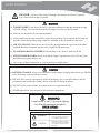
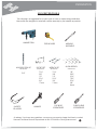
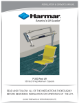
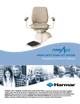
INSTALLATION & OWNER’S MANUAL
P-350 / P-350P / P-350S Pool Lift
350 lbs [159 kg] Maximum Capacity
READ AND FOLLOW ALL OF THE INSTRUCTIONS THOROUGHLY
BEFORE BEGINNING INSTALLATION OR OPERATION OF THE LIFT.
(LEAVE THIS MANUAL WITH OWNER OF LIFT)
TABLE OF CONTENTS
INFORMATION
Product Information ........................................................ 2
Dealer/Installer Information ............................................. 2
SAFETY SUMMARY
Warnings and Cautions.................................................... 3
PREPARATION
Suggested Tools .............................................................. 4
PRE-INSTALLATION
ADA Guidelines (USA only).... ...............................................5
Path of Travel
With Foot Rest............................................................... 6
With Leg Rest................................................................ 7
Pool Deck Requirements
Acceptable Existing Deck.............................................8
New Concrete Pad Under Paver and Sand.................. 10
UNPACKING THE LIFT
PACKAGE CONTENT .........................................................11
INSTALLATION & ASSEMBLY
Charging the Battery....................................................... 12
Anchors and Arm & Base Assembly................................ 13
Seat Support Frame Assembly and Link Shaft................. 14
Seat Assembly................................................................. 15
Foot & Leg Rest Assembly and Adjustment...................... 16
Battery Pack and Control Pendant................................... 17
Portability Kit..................................................................... 18
LIFT OPERATION
Control Pendant ............................................................ 19
Emergency Buttons........................................................ 20
TECHNICAL
Maintenance & Care.. .................................................. 21
Troubleshooting Procedure............................................. 22
EXPLODED VIEWS / PARTS LIST
P350 Assembly........ .......................................................
Hardware Pack.................. .............................................
Arm & Base Assembly......................................................
Seat Assembly.................................................................
Foot Rest Assembly..........................................................
Leg Rest Assembly...........................................................
2
23
2
24
25
26
27
28
WARRANTY INFORMATION
Warranty................. ........................................................ 29
1
INFORMATION
This manual has been provided to assist you with lift installation and
operation. For further assistance please contact your authorized
Harmar dealer or Harmar’s Technical Service Department.
Harmar
2075 47th ST
Sarasota, FL 34234
Tel: 800-833-0478
Tech: 866-378-6648
Fax: 941-308-7399
Email: [email protected]
FILL IN THE FOLLOWING FIELDS TO KEEP FOR YOUR RECORDS:
PRODUCT INFORMATION
Model:______________________________________________
Serial Number:_________________________________________
Purchase Date:_______________________________________
DEALER/INSTALLER INFORMATION
Company Name:____________________________________
Contact Name:______________________________________
Address:____________________________________________
____________________________________________________
Phone Number:______________________________________
Fax Number:________________________________________
Email:______________________________________________
2
SAFETY SUMMARY
!
DANGER - Failure to follow these Warnings, Instructions, and Owner’s Manual
may result in serious injury or death
!
WARNING
WEIGHT LIMIT: Limit for use is ONE (1) person weighing less than the maximum weight
of 350lb [159kg]. Use only for the transfer of a single user, not as a hoist or crane.
Seat belt is to be used at all times during transfer.
Always make sure the area around lift is clear before operating. Never operate the lift with any
person(s) within the operating range of the lift, including on the deck and/or in the water.
ADULT USE ONLY: When in use, the lift is to be operated under the supervison of an adult.
Children should never operate nor play on or around the lift at any time.
NO JUMPING/DIVING/CLIMBING: Do not jump or dive from or climb on the lift.
PINCH/CRUSH HAZARD: Always keep hands, fingers, legs and toes clear of lift arm, base,
and other moving parts when in use.
Save a copy of these instructions in a safe and easily accessible place.
!
CAUTION
BATTERY CHARGE: Always have the battery on the charger charging when not in use. NEVER
leave the battery on the lift when not in use.
DO NOT allow excessive moisture to collect in the battery case. It can affect battery and lift
performance and could lead to battery failure and/or the lift failing to operate.
DO NOT use the seat/seat frame or actuator to move or reposition the lift.
NEVER apply direct water pressure to the electronic components
!
WARNING
Limit for use is one (1) person weighing
less than the maximum weight of
350LB [159KG]
SIGNAL WORDS
!
!
DEFINITION
WARNING
Indicates a hazardous situation
that if not avoided, could result
in moderate to serious injury.
CAUTION
Indicates a hazardous situation
that if not avoided, could result
in moderate to serious property
damage.
3
PREPARATION
SUGGESTED TOOLS
The following is a suggested list of basic tools to have on hand during installation.
Harmar lifts are designed to install with as little assembly by the installer as possible.
HAMMER DRILL
TAPE MEASURE
MARKING
IMPLEMENT
MASONRY DRILL BIT
SOCKET SET
WRENCH SET
ALLEN WRENCH
SPECIFICALLY
SPECIFICALLY
SPECIFICALLY
SPECIFICALLY
7/16”
3/8”
1/2"
9/16"
3/4”
17mm
7/16”
3/8”
1/2"
9/16”
3/4”
17mm
5/8”
SAFETY
GLASSES
FLAT HEAD
SCREWDRIVER
HAMMER
1/8”
5/32”
3/16”
7/32”
5/16”
3/8”
8mm
PHILLIPS HEAD
SCREWDRIVER
As always, if you have any questions, concerns or comments, please feel free to contact
Harmar's Technical Service Department at 866-378-6648 or "[email protected]"
4
PRE-INSTALLATION
ADA GUIDELINES (USA only)
Before installing the P350 Lifts, it is necessary to select the correct location for the Mounting Base. The
P350 Lifts can be installed in a wide variety of locations, but the owner and installer should be aware of the
regulations set forth by the Americans with Disabilities Act (ADA) with concern to lift installations. Fig. 1
below, shows an example of an ADA compliant installation, which incorporates the following ADA rules in
order to be compliant;
·
1009.2.1 POOL LIFT LOCATION: Pool lifts must be located where the water level does not exceed
48 inches [1220mm], unless the entire pool is greater than 48” deep.
(Harmar requires a minimum pool depth of 40”.)
·
1009.2.2 SEAT LOCATION: In the raised position, the centerline of the seat shall be located over
The deck and 16 inches [405mm] minimum from the edge of the pool wall. The deck surface
Between the centerline of the seat and the pool edge shall have a slope no greater than 1:48.
·
1009.2.3 CLEAR DECK SPACE: On the side of the seat opposite the water, a clear deck space shall
be provided parallel with the seat. The space shall be 36 inches [915mm] wide minimum and shall
extend forward 48 inches [1220mm] from a line located 12 inches [305mm] behind the rear edge of
the seat. The clear deck space shall have a slope not greater than1:48.
Fig 1: ADA Deck Requirement
5
PRE-INSTALLATION
PATH OF TRAVEL
WITH FOOT REST
SEAT LOWER SUPPORT
S.L.S MAXIMUM LOAD
LOWER LEG
L.L. MAXIMUM LOAD
Path of Travel can be used
as an aid to determine
most ideal distance the
pool lift is to be mounted
from the pool wall.
10.00
MINIMUM DISTANCE
FROM POOL WALL
17.00
MAXIMUM DISTANCE
FROM POOL WALL
The square and circle
symbols mark the lowest
points on the lift, with no
load, that would be nearest
to the pool wall and
ground during travel.
6
PRE-INSTALLATION
PATH OF TRAVEL
WITH LEG REST
SEAT LOWER SUPPORT
S.L.S MAXIMUM LOAD
LOWER LEG
L.L. MAXIMUM LOAD
Path of Travel can be used
as an aid to determine
most ideal distance the
pool lift is to be mounted
from the pool wall.
10.00
MINIMUM DISTANCE
FROM POOL WALL
17.00
MAXIMUM DISTANCE
FROM POOL WALL
The square and circle
symbols mark the lowest
points on the lift, with no
load, that would be nearest
to the pool wall and
ground during travel.
7
PRE-INSTALLATION
POOL DECK REQUIREMENTS
Fig 2: Minimum Deck Requirements
Fig 3: Lift Location and Hole Specifications
Minimum Deck Requirement:
Minimum concrete slab should be at least 60” x 42” x 4.00” thick, reinforced
(#4 rebar) with a concrete strength of 3000PSI.
Anchors must be installed a minimum of 4” or greater from the edge of the slab
Existing slab does not exhibit any signs of cracking or deterioration.
For proper installation into an existing deck, follow these guidelines.
1
To determine the proper area to install the lift, follow the ADA guidelines, Fig. 1.
2
Verify that the pool deck meets the minimum requirements above, also see Fig.2. If the deck does not
meet these requirements, then the deck needs to be cut and replaced with a new slab that meet these
requirements. The new slab needs to be reinforced with rebar and adhered with epoxy into the
remaining existing deck. Simpson SET epoxy is recommended or equivalent for installation.
!
WARNING
When operating equipment, operator should ALWAYS wear
Personal Protective Equipment
8
PRE-INSTALLATION
Fig 5: Mark hole locations
PARALLEL
POOL
WALL
Fig 4: Lift base parallel with pool wall
Fig 6: Drill four holes
3
Due to Local Electrical Code, it maybe necessary to Bond the Mounting Base to the pools Bonding
Grid with 8ga Copper Wire. See Fig. 2 & 3 for location. Check your Local Electrical Code for proper
Bonding.
4
To determine the proper location to install the lift, use Fig. 3 and the Arm & Base assembly as a
template. Make sure that the lift is an appropriate distance away from the pool wall and that all holes
to be drilled are at least 4” away from any edge of the deck or slab. DO NOT lift the assembly from
the actuator.
5
Mark the four (4) hole locations of the base onto the deck, being sure that the Base is parallel with the
pool wall and the Arm is facing the correct direction, Fig. 4 & 5.
6
Using the Hammer Drill and 5/8 Masonry Drill Bit, drill the four 5/8” diameter holes 2.00” deep.
Make sure the Drill is square to the deck and drill straight down, Fig. 6. Use the Shop Vac to remove
additional dust from holes and surrounding areas.
!
CAUTION
!
DO NOT drill too deep or the anchors will be too low for the supplied fasteners.
WARNING
When operating equipment, operator should ALWAYS wear
Personal Protective Equipment
9
PRE-INSTALLATION
PAVER & SAND REQUIREMENTS
DETERMINING THE LENGTH & WIDTH OF THE RISER
[Hr] is the Height of the Riser
[Lr] is the Length of the Riser
[Wr] is the Width of the Riser
Hr = (Height of Sand) + (Thickness of Paver)
Lr = (Hr x 2) +12
Wr = (Hr x 2) +10
EXAMPLE:
Sand = 2.00” deep and Paver = 3.00” thick
Hr = 2 + 3 = 5.00”
Lr = (5.00 x 2) + 12 = 22.00”
Wr = (5.00 x 2) + 10 = 20.00”
Fig 8: Calculation of Risers length and width
Fig 7: Concrete requirements for Paver & Sand App
1
To determine the proper area to install the lift,
Follow the ADA guidelines, Fig. 1.
2
The minimum deck requirements are similar to those on page 7, but this application requires a Riser in
addition to the footing, Fig. 7. Remove the pavers & sand from the location chosen for the lift and cut
out the underlying foundation. Replace with a new slab with a Riser incorporated on top of it, Fig. 7.
Use Fig. 8 to determine the correct size of the Riser. The new slab needs to be reinforced with rebar
and adhered with epoxy into the remaining existing deck, Fig. 9. Simpson SET epoxy is recommended
or equivalent for installation.
3
Due to Local Electrical Code, it maybe necessary to Bond the Mounting Base to the pools Bonding
Grid with 8ga Copper Wire. See Fig. 7 for location. Check your Local Electrical Code for proper
Bonding.
4
The proper location to install the lift is centered on the riser, use Fig. 7 and the Arm & Base assembly
as a template. Make sure that the lift is an appropriate distance away from the pool wall. DO NOT
lift the assembly from the actuator.
5
Return to page 8 and follow Steps 5 & 6 to finish preparations.
!
WARNING
Fig 9: Reinforcement of concrete
When operating equipment, operator should ALWAYS wear
Personal Protective Equipment
10
UNPACKING THE LIFT
PACKAGE CONTENT
Be sure to check the contents of the boxes against the package checklist,
verifying all parts are included with the lift for a proper installation. If
any parts are missing or damaged, immediately contact the distributor
from which you purchased the lift. DO NOT attempt to install or use
the lift with any missing or damaged parts.
!
NEVER attempt to lift the boxes from the ground
or on/off a vehicle by yourself. Serious injuries
or damage to equipment may result.
WARNING
OR
FOOT REST
ASSEMBLY
(P-350)
LEG REST
ASSEMBLY
(P-350S)
ARM & BASE
ASSEMBLY
SEAT
ASSEMBLY
CONTROL
PENDANT
HARDWARE
PACK
SEAT SUPPORT
FRAME
MOUNTING
BRACKET
CHARGER
CHARGER
11
INSTALLATION & ASSEMBLY
CHARGING THE BATTERY
Before using the pool lift for the first time, the 24V Battery must be fully charged. The battery should be
charged for a minimum of 24 hours on its first initial charge. The battery can be left on the Battery Charger
overnight or until it is needed for use. It is recommended that the battery be fully charged before each use to
ensure that the lift will function for the duration of its immediate use. The battery should never stay on the
lift if the lift is not being used.
1
Installing 24V Battery onto Battery Charger:
Place Battery onto Battery Charger and rotate up until the Battery engages the Mounting Bracket.
The latch on the Battery will click when engaged properly and will be fixed tightly on top of the
Charger. When the Charger is plugged in, the “ON” light will illuminate GREEN. When the
Battery is properly mounted onto the Charger, the “Charge” light will illuminate ORANGE.
Once the Battery is FULLY charged, the “Charge” light will turn off and the Battery is ready
to be used.
CLICK
24V
BATTERY
MOUNTING
BRACKET
BATTERY
CHARGER
2
Mounting
Bracket
Recharging 24V Battery
To recharge the Battery, grip the top-rear of
of the Battery and squeeze the clip. This will
unlatch the Battery from the Mounting Bracket.
The Battery can now be installed onto the
Battery Charger as described above.
! CAUTION
ALWAYS have the Battery charging
on the Charger when not in use.
12
24V
Battery
INSTALLATION & ASSEMBLY
ARM & BASE ASSEMBLY
1/2-13 x 0.75
HEX HEAD
(x4)
Insert Drop-In Anchors
3
Before inserting the Drop-In Anchors, apply a small
amount of Epoxy into the four anchor holes and to the
outside of the anchors. Insert the Drop-In Anchors into
the holes and gently tap them in being careful not to
damage the thread (they should sit flush with or just
below the deck). Once in place, using the Setting Tool,
forcefully strike the inside of the anchors to set them.
½ SPLIT LOCK
WASHER
(x4)
DROP-IN
ANCHOR
(x4)
ARM & BASE
ASSEMBLY
INSERT
!
APPLY
SMALL
AMOUNT
OF
EPOXY
TO HOLES
& ANCHORS
CAUTION
Anchor must be set flush or
slightly below surface
!
!
4
Fasten Arm & Base Assembly
SETTING
TOOL
CAUTION
CAUTION
5
DO NOT apply too much Epoxy
DO NOT lift from the Actuator
Attach Copper Wire
Fasten copper wire to Grounding Lug located
within the Base of the assembly.
CHECK LOCAL ELECTRICAL CODE
Align mounting holes with anchors, and tightly
fasten with spring lock washer and bolts.
GROUNDING
LUG
8 GA
COPPER WIRE
13
INSTALLATION & ASSEMBLY
Attach Seat Support Frame
6
LEFT
HAND
FLANGE
BEARING
(x2)
RIGHT
HAND
The P350 has ambidextrous seating which
allows the seat to be set to face either side
of the pool dependant on pool installion
and/or preference, shown to the left.
Once chosen, grease the surfaces
of the Flange Bearings and the Seat
Support Frame, if necessary, as shown
in the picture. Insert the Flange Bearings
into the Arm and insert the Seat Support
Frame into the bearings, below.
SEAT SUPPORT
FRAME
ADD
GREASE
RIGHT
HAND
INSERT
INSERT
ARM & BASE
ASSEMBLY
7
Link Shaft Adjustment
The Link shaft should be attached and fastened on
the opposite side of the Seat Support Frame. If this
is not the case, then simple unfasten the Link Shaft
and attach it onto the otherside of the base.
LINK
SHAFT
BASE
3/8-16
NYLON
NUT
8
Attach Rotation Plate
Rotate the Rotation Plate forward and
fasten to Seat Support Frame with the
appropriate fasteners.
ROTATION
PLATE
3/8
NYLON
WASHER
3/8-16 x 1.50
SOCKET
HEAD
1/2-13
NYLON
NUT
3/8-24 x 1
BUTTON
HEAD W/
NYLON
PATCH
SPRING
LOCK
WASHER
14
INSTALLATION & ASSEMBLY
9
Attach Seat Assembly
Rest Seat Assembly onto Seat Support
Frame, align holes, and tightly fasten
with respective fasteners.
SEAT
ASSEMBLY
1/4-20 x 2.00
BUTTON HEAD
(x2)
1/4-20
NYLON NUT
(x4)
¼ WASHER
(x2)
1/4-20 x 1.50
BUTTON HEAD
(x2)
!
CAUTION
DO NOT unfasten or disassemble Seat from Back & Lower Supports.
SEAT
BACK
SUPPORT
ASSEMBLY
LOWER
SUPPORT
15
INSTALLATION & ASSEMBLY
10
Attach Foot & Leg Rest Assembly
The foot rest, shown, and leg rest are designed
to be ambidextrous, to allow for right & left
hand seating. The Foot & Leg Rest should
always be on the side nearest to the water. To
attach the Assembly, simply align the holes on
the Foot & Leg Rest Assembly with that of the
Lower Seat Support and fasten with the supplied
hardware.
3/8-16 X 2.50
BUTTON HEAD
(x2)
LOWER SEAT
SUPPORT
3/8-16
NYLON NUT
(x2)
FOOT REST
ASSEMBLY
LEG REST
ASSEMBLY
11
Foot & Leg Rest Adjustment
The Foot Rest has two setting, high and low,
and the Leg Rest has three settings, high,
medium, and low, depending on the desired
height. To adjust the height of the Foot Rest,
remove the bolt, adjust the height up or
down, align the holes at the desired height,
reinsert the bolt into the correct hole, as
shown, and fasten.
FOOT REST BOLT SETTINGS
(Bolt Location)
HIGH
1/2-13 X 2.50
BUTTON HEAD
LOW
LEG REST BOLT SETTINGS
(Bolt Location)
1/2-13
NYLON NUT
HM L
16
HM L
INSTALLATION & ASSEMBLY
12
Installing 24V Battery onto Lift:
Mounting
Bracket
Place FULLY charged Battery onto Control Box
and lift up until the Battery engages the Mounting
Bracket. The latch on the Battery will click when
engaged properly and will be fixed tightly on top
of the Control Box.
24V
Battery
CLICK
Control Box
!
ALWAYS detach the Battery when NOT in use and
place onto the Charger to ensure a FULLY operating
Battery when needed
WARNING
13
Actuator
Connecting Control Pendant:
Insert Control Pendant plug into Control Box port by aligning
key on plug with key way on the port. This will ensure that the
pins on the plug align with that if the Control Box. Press firmly to
ensure that the plug is fully seated within the port. Also, firmly
press in the actuator plug to ensure that it is seated properly into
its respective port.
Control
Pendant
Plugs
Fully
Seated
Control Box
Control
Pendant
Plug
Actuator
Plug
!
WARNING
Lift WILL NOT operate if the Control Pendant and/or the actuator plugs
are NOT fully seated within their respective ports of the Control Box.
17
INSTALLATION & ASSEMBLY
PORTABILITY KIT
[included with P-350P]
This kit is designed to allow the user/owner to transport the pool lift, P350, when not in
use, to and from storage. Be sure to check the contents of the package and verify that all
parts and hardware are present before installing. If any parts are missing contact the
distributor from which the kit/lift was purchased.
PARTS & HARDWARE
STAND
HAIR PIN (x2)
1/2-13 X 1.00
BUTTON HEAD
(x4)
1/2” WASHER (x2)
TOOL REQUIRED
1/2” LOCK NUT
(x4)
RACHET
3/4” SOCKET
3/32 ALLEN
5/16 ALLEN
1/2” WASHER
(x4)
8-32 X 1/2”
BUTTON HEAD
(x2)
#8 EXT WASHER (x2)
WHEEL
BRACKET
PULL HANDLE
WHEEL (x2)
INSTALLATION
Align all parts with respective holes and tighten
all fasteners. The Stand is to be installed on the
same side as the seat and the Wheel Bracket
Assembly & Pull Handle on the opposing side.
!
CAUTION
STAND
The lift should never be operated when not fastened to the deck or in storage.
Lift should always be in its most up position when moved and/or stored.
Items should never be rested on the lift or seat when not in use.
WHEEL BRACKET ASSEMBLY
18
PULL HANDLE
LIFT OPERATION
BEFORE OPERATING THE LIFT:
1
Always make sure that the area around the lift is clear before operating.
2
Never operate the lift with any person within the operating range of the lift, including
the deck and/or water.
3
DO NOT allow anyone to operate the lift without adult supervision.
4
DO NOT allow children to play on or around the lift at any time.
5
Check all fasteners and joints for tightness and wear before each use.
OPERATING THE LIFT
UP
DOWN
To move the lift into the pool,
press and hold the DOWN
button on the Control Pendant.
To move the lift out of the pool,
press and hold the UP button
on the Control Pendant.
To STOP moving, release
the button at the desired
depth.
To STOP moving, release
the button once the lift is at
its highest point or has stopped.
!
CAUTION
If the “DOWN” button is NOT released, the lift will
continue to a depth below the crest of the water.
UP
DOWN
! CAUTION
Lift is ALWAYS to be operated under the direct supervision of an Able-Bodied Adult.
19
LIFT OPERATION
EMERGENCY BUTTONS
On the front of the Control Box there are two emergency
buttons, “EMERGENCY STOP” & “EMERGENGY UP.”
EMERGENGY
“STOP” BUTTON
EMERGENCY
“UP” BUTTON
DEPRESS
CLICK
1
Emergency “STOP” Button:
The Emergency Stop Button is the larger red button on the
front of the Control Box. To ENABLE the “Emergengy Stop”
button, depress the button so it clicks and locks in its depressed
position. This will disable the lift and stop it immediately at the
location in which the Emergency Button was depressed. The
button will remain locked until it is released.
!
TURN
CLOCKWISE
WARNING
The lift WILL NOT function until the
Emergency Button has been released.
To RELEASE the “Emergency Stop” button and resume operation
of lift, simply turn the button clockwise until the it pops out.
2
Emergency “UP” Button:
The Emergency Up Button is the small
recessed button located next to the word
“EMERGENCY” on the front of the Control
Box. To use; take a pen, pencil, or any object
with a point, depress the button, and hold until
the lift is all the way up. This will bypass the
Control Pendant and raise the lift.
!
WARNING
This function will only work if the Battery is sufficiently
charged, properly attached, and if the Control Box is
operating properly.
20
DEPRESS
TECHNICAL
MAINTENANCE & CARE
The lift should be cleaned routinely to ensure the life and integrity of the lift. Cleaning product is entirely
up to the owner as there are many to choose from. For routine cleaning, it is recommended to use gentle
soaps, detergents, or a diluted mixture of ammonia. If scrubbing is required for tough stains, use a soft
scrub with brisk rubbing.
DAILY USE:
If the lift is used daily, be sure to wash the lift at the end of each day. Wash the lift with fresh water a mild
soap and a soft cloth. Do not use bristled brushes or steel wools to clean the lift as it will scrap off the
powder coating. Check that the lift is working properly and then place the battery on the charger. It is
recommended that the battery be charged after every use.
WEEKLY USE:
If the lift is used weekly, follow the same procedure as above. Also be sure to check all of the contact points
(terminals) for damage or corrosion. If you notice corrosion gently clean the terminals. To clean corrosion
from the terminals use a q-tip and some rubbing alcohol. If the corrosion is particularly stubborn try using a
3M scotch brite pad, but be careful not to damage the terminals. Apply dielectric grease to the terminals
after cleaning them. This will help to prevent further corrosion. Do not leave the battery on the lift when not
in use. Always store the battery on the charger whenever the lift is not being used.
MONTHLY USE:
If the lift is used monthly, follow the same steps as above. Also check the nuts and bolts to make sure they
are securely fastened (this is always a good idea, no matter how often or infrequently the lift is used). Also
make sure to store the battery on the charger and not on the lift. Leaving the battery on the lift for extended
periods will significantly shorten the battery’s life span.
STORED/OCCASIONAL USE:
If the lift is not used often and is stored for an extended period of time, follow all of the steps above. Check
for rusting at all crevice, weld points, and fasteners. If you notice rusting spray some WD-40 on the affected
area and take a 3M scotch brite pad and rub briskly. Afterwards be sure to wash and rinse the lift again with
soap and fresh water. When storing the lift make sure it is in a dry area and covered. DO NOT STORE in or
around pool chemicals.
!
CAUTION
ALWAYS clean the lift with FRESH water only.
NEVER use the pool or chemically treated water for cleaning.
21
TECHNICAL
TROUBLESHOOTING PROCEDURE
**THE BATTERY SHOULD BE FULLY CHARGED BEFORE TROUBLESHOOTING**
Issue: Lift stopped moving over the water.
1
DEPRESS
Procedure: Push the “EMERGENCY” BUTTON.
If the lift gets stuck over or in the water and the Control
Pendant does not raise the lift, then using a pen, pencil,
or pointed object, depress the button located on the
Control Box next to the word “EMERGENCY”. This
will bypass the Control Pendant and raise the lift. If this
does not raise the lift, then the remote may be fine and the
problem is with either the Battery, Control Box, or damaged
cables.
Issue: Lift will not operate, when buttons on control pendant is pressed.
1
Procedure: Check Cable Connections to Control Box.
Check For
Corrosion
Before
Plugging In
Check underneath the Control Box to be sure that all cables
are properly seated within their respective ports. The plugs
should be recessed within those ports. Verify by unplugging
both the Control Pendant and the Actuator cables. Check that
there is no corrosion or damage to the connectors/pins. Plug the
Control Pendant back into the Control Box by aligning key
on plug with key way on the port. Press in firmly to ensure
that the plug is fully seated within the port. For the actuator,
insert the cables jack into its port and press in firmly.
2
Procedure: Check Battery Connections.
Check that the Battery Pack is properly secured onto the
Mounting Bracket. The Battery pack should be locked
in place with nearly no movement if shaken. Verify by
unlatching from Mounting Bracket. Check that there is
no corrosion or damage to the terminals on the Battery
Pack and Control Box. If corroded or dirty, clean off
using rubbing alcohol. Once cleaned, it is recommended
to add dielectric grease to the terminals to prevent corrosion
and to ensure good electrical contact. Reinstall the Battery
Pack onto the Control Box. When properly engaged onto the
Mounting Bracket, the latch on the back of the Battery
Pack will “CLICK”. If lift fails to lift, then try another fully
charged battery. If lift still fails to operate, then the Control Box
will need to be replaced. Contact an Autorized lift dealer for
component replacement.
!
CAUTION
Plugs
Fully
Seated
The lift WILL NOT function if the Battery is not
charged or if the Control Box is damaged or
malfunctioning.
22
CLICK
EXPLODED VIEW / PARTS LIST
P350 ASSEMBLY
3
2
1
5
4
ASSEMBLY PARTS
ITEM
1
2
3
4
5
QTY
1
1
1
1
1
PART NO.
210-2L02-C
N/A
N/A
N/A
H00-2A05-A
DESCRIPTION
SEAT SUPPORT FRAME
ARM & BASE ASSEMBLY
SEAT ASSEMBLY
FOOT REST ASSEMBLY
HARDWARE PACK
23
EXPLODED VIEW / PARTS LIST
HARDWARE PACK
8
4
4
2
5
2
7
1
6
2
14
4
11
1
1
4
13
1
9
4
12
2
10
2
3
1
2
1
ASSEMBLY PARTS
ITEM
1
2
3
4
5
6
7
8
9
10
11
12
13
14
QTY
4
1
1
2
2
2
1
4
4
2
1
2
1
4
PART NO.
540-2L03-A
902-3L05-A
SB1-037-2-6_50
BHCS-0_25-20--1_50-SS
BHCS-0_25-20--2_00-SS
BHCS-0_37-16--2_50-SS
BHCS-0_37-24--1_00-NP-SS
HHCS-0_50-13--0_75-SS
NUT-0_25-20-NYLOCK-SS
NUT-0_37-16-NYLOCK-SS
NUT-0_50-13-NYLOCK-NTE-SS
WASH-0_25-0_62--0_04-RH-SS
WASH-0_37-0_68--0_09-SL-SS
WASH-0_50-0_87--0_12-SL-SS
DESCRIPTION
1/2-13 DROP IN ANCHOR
OWNERS MANUAL
3/8 DIA X 6.50" L
BUTTON HEAD, 1/4-20 X 1.50, SS
BUTTON HEAD, 1/4-20 X 2.00, SS
BUTTON HEAD, 3/8-16 X 2.50, SS
BUTTON HEAD W/ NYLON PATCH, 3/8-24 X 1.00, SS
HEX HEAD, 1/2-13 X 0.75, SS
NYLOCK NUT, 1/4-20 , SS
NYLOCK NUT, 3/8-16, SS
NYLOCK NUT, THIN, 1/2-13, SS
WASHER, FLAT, 1/4", SS
WASHER, SPRING LOCK, 3/8 ID, SS
SPLIT LOCK WASHER 1/2, SS
24
EXPLODED VIEW / PARTS LIST
ARM & BASE ASSEMBLY
26
26
23
7
24
20
8
12
23
12
11
25
17
13
26
22
2
3
18
13
27
15
21
22
19
5
26
16
17
14
6
19
18
10
1
4
20
9
27
21
ASSEMBLY PARTS
ITEM
1
2
3
4
5
6
7
8
9
10
11
12
13
14
QTY
1
1
1
1
1
1
1
1
1
1
1
2
2
1
PART NO.
200-2L05-C
201-2L02-C
201-2L05-C
299-2L02-A
320-2L02-A
321-2L02-A
517-2L02-C
531-2L02-C
557-2L02-A
599-2L02-A
801-2L02-A
ALA05010
ALA15110
ALA21094
ASSEMBLY PARTS
DESCRIPTION
BASE WELDED ASSEMBLY
ARM
SPACER WELDED ASSEMBLY
COPPER SET SCREW LUG
BATTERY PACK
CONTROL BOX
ROTATION PLATE
LINK SHAFT
ARM PIN
CONTROL MOUNTING BRACKET
ACTUATOR
FLANGE BEARING 2 INCH
BRONZE FLANGE BUSHING, 1"
STICKER, "CAUTION"
15
16
17
18
19
20
21
22
23
24
25
26
27
25
1
1
2
2
2
2
2
2
2
1
1
4
2
PART NO.
910-2L02-A
ALA99995
BHCS-0_25-20--0_37-NP-SS
BHCS-0_50-13--0_75-NP-SS
BHCS-10-24--0_62-SS
NUT-0_37-16-NYLOCK-SS
NUT-10-24-NYLOCK-SS
NUT-M10-1_5-NYLOCK-SS
SHCS-0_37-16--1_50-SS
SHCS-M10-1_5--55MM-SS
SHCS-M10-1_5-130MM-SS
WASH-0_37-1_00-0_05-N
WASH-0_50-1_37-0_12-RH-SS
DESCRIPTION
STICKER
LABEL, SERIAL NUMBER
BUTTON HEAD W/NYLON PATCH, 1/4-20 X 0.37, SS
BUTTON HEAD W/ NYLON PATCH, 1/2-13 X 0.75, SS
BUTTON HEAD, 10-24 X 0.62, SS
NYLOCK NUT, 3/8-16, SS
NUT, NYLOCK, 10-32, SS
NYLOCK NUT, M10 X 1.5, SS
SOCKET HEAD, 3/8-16 X 1.50, SS
SOCKET HEAD, M10-1.5 X 55, SS
SOCKET HEAD CAP SCREW M10-1.5 X 130MM , SS
WASHER, 0.40 ID X 1.00 OD X 0.05, WHITE NYLON
WASHER, FLAT, 1/2", SS
EXPLODED VIEW / PARTS LIST
SEAT ASSEMBLY
3
2
4
2
16
1
14
1
7
2
9
1
16
1
13
2
2
1
6
1
8
1
14
1
5
2
11
2
12
4
10
2
9
3
15
5
12
1
15
1
12
1
15
1
15
1
1
1
ASSEMBLY PARTS
ITEM
1
2
3
4
5
6
7
8
9
10
11
12
13
14
15
16
17
QTY
1
1
2
2
2
1
2
1
4
2
2
6
2
2
8
2
2
PART NO.
204-2L02-C
213-2L02-C
214-2L02-C
410-2L02-A
542-2L02-C
900-2L02-A
906-2L02-A
911-3L02-A
SPCR-0_25-0_50--0_18-N
ALA25025FP
BHCS-0_25-20--1_25-SS
BHCS-0_25-20--1_50-SS
BHCS-0_25-20--2_50-SS
BHCS-0_31-18--1_75-SS
NUT-0_25-20-NYLOCK-SS
NUT-0_31-18-NYLOCK-SS
WASH-0_25-0_62--0_04-RH-SS
DESCRIPTION
SEAT LOWER SUPPORT
BACK BRACKET
ARMREST
PLUG (1" DIA RND TUBE)
PLATE
SEAT
RUBBER BUMPER
SEAT BELT
SPACER, 1/4 ID X 0.18, NYLON
END CAPS
BUTTON HEAD, 1/4-20 X 1.25, SS
BUTTON HEAD, 1/4-20 X 1.50, SS
BUTTON HEAD, 1/4-20 X 2.50, SS
BUTTON HEAD, 5/16-18 X 1.75, SS
NYLOCK NUT, 1/4-20 , SS
NYLOCK, 5/16-18, SS
WASHER, FLAT, 1/4", SS
26
17
2
EXPLODED VIEW / PARTS LIST
FOOT REST ASSEMBLY
11
3
12
11
8
9
4
8
7
6
10
2
1
10
5
13
7
13
13
13
13
13
ASSEMBLY PARTS
ITEM
1
2
3
4
5
6
7
8
9
10
11
12
13
QTY
1
1
1
1
1
1
2
2
1
2
2
1
6
PART NO.
410-2L02-A
211-2L02-C
212-2L02-C
416-2L02-A
567-2L02-C
568-2L02-C
BHCS-0_25-20--1_50-SS
BHCS-0_37-16--2_50-SS
BHCS-0_50-13--2_50-SS
NUT-0_25-20-NYLOCK-NTE-SS
NUT-0_37-16-NYLOCK-SS
NUT-0_50-13-NYLOCK-NTE-SS
PHTS-10-32--0_37-SS
DESCRIPTION
PLUG (1" DIA RND TUBE)
FOOT PLATE SUPPORT
HOUSING WELDMENT
FOOT PLATE
LOWER LEG TUBE
UPPER LEG TUBE
BUTTON HEAD, 1/4-20 X 1.50, SS
BUTTON HEAD, 3/8-16 X 2.50, SS
BUTTON HEAD, 1/2-13 X 2.50, SS
NYLOCK NUT, THIN, 1/4-20, SS
NYLOCK NUT, 3/8-16, SS
NYLOCK NUT, THIN, 1/2-13, SS
PAN HEAD, THREAD FORMING, 10-32 X 0.37, SS
27
EXPLODED VIEW / PARTS LIST
LEG REST ASSEMBLY
2
1
9
1
12
1
3
1
10
1
14
1
7
1
8
1
1
1
13
6
5
1
4
1
6
1
11
1
ASSEMBLY PARTS
ITEM
1
2
3
4
5
6
7
8
9
10
11
12
13
14
QTY
1
1
1
1
1
1
1
1
1
1
1
1
6
1
PART NO.
200-3L12-C
212-2L02-C
400-3L12-A
410-2L02-A
500-3L12-C
501-3L12-C
ALA16031
BHCS-0_25-20--1_50-SS
BHCS-0_50-13--2_50-SS
H106600
NUT-0_25-20-NYLOCK-NTE-SS
NUT-0_50-13-NYLOCK-NTE-SS
PHTS-10-32--0_37-SS
RIV-188-SS
DESCRIPTION
LEG PLATE SUPPORT
FOOT REST HOUSING
LEG REST
PLUG (1" DIA RND TUBE)
UPPER LEG TUBE
LOWER LEG TUBE
FAST PIN CHAIN
BUTTON HEAD, 1/4-20 X 1.50, SS
BUTTON HEAD, 1/2-13 X 2.50, SS
HOV SWA SAFETY PIN
NYLOCK NUT, THIN, 1/4-20, SS
NYLOCK NUT, THIN, 1/2-13, SS
PAN HEAD, THREAD CUTTING, 10-32 X 0.37, SS
RIVET
28
WARRANTY INFORMATION
POOL LIFTS
THREE YEAR NON-TRANSFERABLE LIMITED WARRANTY
Harmar warrants ONLY to the original purchaser of the product manufactured by Harmar,
assembled and installed in accordance with Harmar’s assembly and installation instructions,
properly used and maintained, shall be free from defects in material and workmanship for a
period of three (3) years from the date of original purchase, with the exception of the following
items: Battery Pack and Seat each have a one (1) year warranty from the date of original
purchase.
The Pool Lift has a three (3) year warranty on the frame/mechanical, electrical & motor
components, excluding powder coated paint finish, which may become scratched or
chipped with normal use. The Battery Pack and Seat, including seat frame, spreader bars,
sling, and powder coat paint finish have a one (1) year warranty. Within the warranty period,
Harmar will repair or replace any item deemed to be found defective. Normal maintenance
and care of the unit, including charging the battery when not in use is recommended.
IMPORTANT: Weight capacity of pool lift seat and its seat support frame is NOT to exceed the
MAXIMUM LIFTING CAPACITY of 350 lb [159 kg].
The warranty is non-transferable and is subject to the following terms and conditions:
Harmar shall not be responsible for the cost of removal or replacement of any defective Harmar product, nor for any
other expenses or for damages which might be incurred in such removal or replacement.
This warranty specifically excludes fading or staining of material, rust or corrosion of any metallic material, and
cleaning of Harmar products.
This warranty relates only to defects in material and workmanship and DOES NOT cover any damages or failures
resulting from other causes, including, but not limited to Acts of God, misuse or abuse, accident or negligence, fire,
improper assembly or installation, chipping or flaking of powder coating, weather damages, including ice and sand,
improper maintenance of any products, or normal wear and tear from day to day use.
Damages induces by the improper use of chemicals is not covered by this warranty.
In the event that any products are altered, repaired, or improperly installed or improperly used by anyone without
prior written approval by Harmar, all warranties will be void.
Harmar shall not be liable for any consequential, special or incidental damages, including, but not limited to any
damages for loss of use of pools or injuries to person or property, and any claims therefore are hereby specifically
disclaimed and excluded. Some states do not allow the exclusion or limitation of incidental, special or consequential
damages, so the above limitation or exclusion may not apply to you. This warranty gives you specific legal rights and
you may also have other rights, which may vary from state to state. The warranty is extended to, and enforceable
only by the original retail purchaser.
If any Harmar products fail during the warranty period as a result of a defect in material or workmanship covered by
this warranty, the original retail purchaser is to contact the installer of the lift or place of purchase to assess the defect
or damage. Defective parts must be returned, prepaid, to Harmar at 2075 47th Street, Sarasota, Florida 34234, for
inspection prior to credit, repair or replacement at Harmar’s option. Harmar’s sole obligation and the exclusive
remedy under this warranty is limited to such credit, repair or replacement.
A new warranty period shall not be established for the repaired or replaced products. Such products shall remain
under warranty for the remainder of the original warranty period on the original products purchased.
29
WARRANTY INFORMATION
This written limited warranty constitutes the final, complete and exclusive statement of
warranty terms. No person or organization is authorized to make any other specific or implied
warranties or representations on behalf of Harmar.
The warranties set forth herein are in lieu of all other warranties, expressed or implied, which
are hereby disclaimed and excluded, including without limitation any warranty of
merchantability or fitness for a particular purpose or use.
The sole and exclusive remedies for breach of any and all warranties with respect to the
products shall be limited to repair or replacement at Harmar’s designated factory location, or
duly appointed distributor, or in place at Harmar’s option. In no event shall Harmar’s liability
exceed the entire amount paid to Harmar by th original purchaser for the failed or defective
product.
In no event shall Harmar be liable for any incidental, consequential, special, indirect, punitive
or exemplary damages or lost profits from any breach of this limited warranty or otherwise
30
THANK YOU FOR MAKING HARMAR AMERICA’S LEADER IN LIFTS
2075 47th Street, Sarasota, Florida 34234 | www.harmar.com | 1-800-833-0478
902-3L05-AA
053013