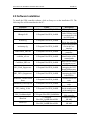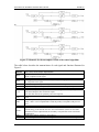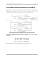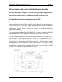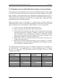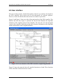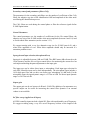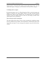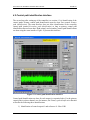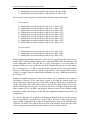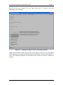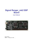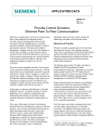
1
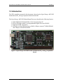
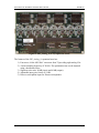
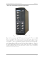
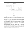
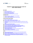
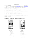
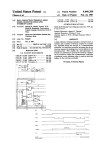
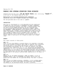
M. ZEN 3-Channel X-LMS Controller User Manual Version 3.1 Written by: Alex Boudreau, Ph.D. Soft dB August 2007 User manual for the ZEN 3-channel X-LMS controller Soft dB inc. TABLE OF CONTENTS 1.0 Introduction................................................................................................................... 3 2.0 Software Installation ..................................................................................................... 7 3.0 Detailed Control Algorithm .......................................................................................... 9 3.1 Uncoupled Algorithm Description............................................................................ 9 3.1.1 General Description ........................................................................................... 9 3.1.2 Subtracting the control output contributions from the reference signals......... 12 3.1.3 Adding low-level white noise to reference signals .......................................... 14 3.1.4 Adaptative step size normalization technique.................................................. 15 3.2 Description of the control algorithm for the coupled case...................................... 16 3.3 Description of the control path identification algorithm......................................... 17 3.3.1 Identification algorithm implemented on the DSP .......................................... 17 3.3.2 Adaptative step size and identification technique in noisy conditions ............ 19 4.0 User interface .............................................................................................................. 20 4.1 Configuration interface of the controller ................................................................ 22 4.2 Control path identification interface ....................................................................... 27 4.3 Control interface ..................................................................................................... 30 4.4 Autonomous mode (optional) ................................................................................. 34 ZEN User Manual p. 2 User manual for the ZEN 3-channel X-LMS controller Soft dB inc. 1.0 Introduction The ZEN controller presented in this document is based on the Signal Ranger Mk2 DSP board and the SR2_Analog8 expansion board from Soft dB. The Signal Ranger Mk2 DSP (Digital Signal Processor) board has the following features: 1) 2) 3) 4) DSP (TMS320C5502@300 MHz) 16-bit fixed point from TI. FPGA (XS3S400) with 63 user-programmable digital I/Os from XILINX. High speed USB 2.0 interface. 64 kbytes on-chip (DSP) dual-access RAM, 4 Mbytes external 75 MHz SDRAM and 2 Mbytes external Flash ROM. Figure 1: Signal Ranger Mk2 DSP board (without the SR2_Analog_8 expansion board) ZEN User Manual p. 3 User manual for the ZEN 3-channel X-LMS controller Soft dB inc. Figure 2: SR2_Analog_8 (or 16) expansion board The features of the SR2_Analog_8 expansion board are: 1) Four stereo 16-bit ADC/DAC converters from TI providing eight analog I/Os. 2) A main sampling frequency of 78 kHz. The optimization rate can be adjusted using a decimation factor. 3) Signal on noise ratio: 88 dB (input) and 90 dB (output). 4) Adjustable input gain, from 0 to 54 dB. 5) Direct or microphone input for Electret microphones. ZEN User Manual p. 4 User manual for the ZEN 3-channel X-LMS controller Soft dB inc. The two ZEN controller boards are housed in a metal enclosure: Figure 3: Metal enclosure of the ZEN controller Figure 4 shows a schematic of the ZEN active control system. In addition to the DSP board, the system includes a PC (with a dedicated user interface) to control the DSP board over a USB link. The controller provides six inputs (three for the reference signals and three others for the error signals). Each input can be designated via software as either a microphone or a direct input. With the microphone input selected a bias is provided, and a high pass filter at 16 Hz is activated. The control system includes three outputs for the control signals. Figure 4 shows an acoustic example that includes six microphones and three loudspeakers. However, the control system is generic and can be used with other types of sensors and actuators. ZEN User Manual p. 5 User manual for the ZEN 3-channel X-LMS controller Soft dB inc. Figure 4: Schematic of the ZEN 3-channel control system from Soft dB The real-time algorithm running on the DSP board synthesizes the output signals to minimize the noise measured by the three error sensors. The X-LMS algorithm with feedforward and a filtered reference LMS optimization is used to minimize the error signals. This controller can be used in coupled or uncoupled mode to take into account the interaction between each channel (see section 3.0 for more details). The control system includes a PC user interface for adjusting algorithm parameters and analyzing the control results. Note that the ZEN control system can be used stand-alone if you have the Autonomous Mode option. With this option, the ZEN controller can automatically start the control when power-up. But before, the ZEN controller must be adjusted and configured with the PC interface. The current documentation contains detailed explanations of how the control system works. Section 2.0 explains the installation of the PC user interface and the USB driver for the DSP board. Section 3.0 provides details on the control algorithm running on the DSP. Section 4.0 shows how the PC interface works. This last section also offers a stepby-step procedure for applying a control on a given physical system. ZEN User Manual p. 6 User manual for the ZEN 3-channel X-LMS controller Soft dB inc. 2.0 Software Installation To install the ZEN controller software, click on Setup.exe on the installation CD. The following files will be transferred to the PC: File name ZEN_Ver3_x.exe Folder C:\Program Files\ZEN_SoftdB SRanger2.dll C:\Program Files\ZEN_SoftdB default.cfg C:\Program Files\ZEN_SoftdB mainsetup.cfg C:\Program Files\ZEN_SoftdB CodeControl_SR2.out C:\Program Files\ZEN_SoftdB codeiden_sr2.out C:\Program Files\ZEN_SoftdB CodeMute_SR2.out C:\Program Files\ZEN_SoftdB SR2_Flash_Support.out C:\Program Files\ZEN_SoftdB SR2_FPGA_Support.out C:\Program Files\ZEN_SoftdB SR2Kernel_HostDownloa d.out C:\Program Files\ZEN_SoftdB SR2Kernel_PowerUp.out C:\Program Files\ZEN_SoftdB SR2_Analog_16.rbt C:\Program Files\ZEN_SoftdB ZEN_UserManual.pdf C:\Program Files\ZEN_SoftdB\doc SRm2.inf SRm2.sys ZEN User Manual C:\Program Files\ZEN_SoftdB\DriverUSB C:\Program Files\ZEN_SoftdB\DriverUSB Description PC user interface DLL (Dynamic Linked Library) used to communicate with the DSP board Default configuration file for the controller Default configuration file for the user interface DSP code for the controller DSP code for the identification of the control paths DSP code for setting all outputs to zero DSP code for managing the DSP board flash memory DSP code for managing the DSP board FPGA Communication DSP code Communication DSP code FPGA configuration for the management of the analog I/Os User manual for the ZEN controller USB driver for the SR Mk2 USB driver for the SR Mk2 p. 7 User manual for the ZEN 3-channel X-LMS controller Soft dB inc. The most important files are: 1) ZEN_Ver3_x.exe: the PC user interface of the ZEN controller 2) ZEN_UserManual.pdf: the ZEN user manual. Once the software is installed, the DSP board can be connected to the PC. At first connection, Windows asks for the USB driver. During USB installation, the user must manually specify the following folder: C:\Program Files\ZEN_SoftdB\DriverUSB. ZEN User Manual p. 8 User manual for the ZEN 3-channel X-LMS controller Soft dB inc. 3.0 Detailed Control Algorithm The control algorithm running on the DSP board is an X-LMS feed-forward algorithm with filtered reference. The X-LMS optimization is done in real time for an optimization frequency that is selectable between 78.125 Hz and 78.125 kHz. The main sampling frequency is fixed at 78.125 kHz and the user can adjust the optimization rate by specifying a decimation factor. When the controller is used in coupled mode, the secondary cross-paths (see section 3.2 for details) are taken into account during LMS optimization. In uncoupled mode, the control system acts like three separate mono-channel controllers. The maximum number of coefficients for the control filters depends on many factors: the optimization frequency, the number of channels and the number of coefficients for the control path filters. For example, a 3-channel case with an optimization frequency of 15.6 kHz (main frequency at 78.125 kHz and decimation factor of 5), the controller can optimize up to 256 coefficients in coupled mode. In uncoupled mode, 909 coefficients can be optimized in real time. In both cases, the number of coefficients for primary and secondary control paths is 400. The next sections describe in-detail the control algorithm running on the DSP board. Coupled and uncoupled modes will be explained. Then, the technique used to identify the primary and secondary control paths will be presented. 3.1 Uncoupled Algorithm Description 3.1.1 General Description Figure 5 shows a schematic of the algorithm for the uncoupled case. ZEN User Manual p. 9 User manual for the ZEN 3-channel X-LMS controller Soft dB inc. Figure 5: Schematic for the uncoupled version of the control algorithm The table below describes the nomenclature of each signal and function illustrated in Figure 5: Signal or function Rx(n) Cx(n) Ex(n) Mu F_Rx F_Ex F_Cx CxEy CxRx Wx Norm x LMS_x W.N. Description Note: x and y are the output / input numbers Reference signal x. These signals are filtered by an adjustable high-pass filter to remove the DC component of the signal. Output control signals x. Error signals x. These signals are filtered by an adjustable high-pass filter to remove the DC component of the signal. Normalized adaptative step size. Only one Mu is used for all optimizations. Adjustable band-pass or low-pass filter to force the control on a specific spectral zone. Adjustable band-pass or low-pass filter to force the control on a specific spectral zone. Adjustable band-pass or low-pass filter to avoid aliasing on control output signals. This is the same band-pass filter used on the inputs. Note: this filter can also be optionally removed if required. This filter represents the secondary control path between control output x and error sensor y. This filter represents the primary control path between control output x and reference sensor x. Note: even if coupled mode is used, the primary cross-paths (CxRy) are not used. Control filter x. Function for the normalization of the adaptative step size. The normalization is done with the energy of the filtered reference. Note: normalization is done for each LMS function but even in coupled mode, the secondary cross-path filter is not used for the normalization. Optimization function (LMS) for control filter x. White noise generator. The output of this generator is added to the reference signals. The ZEN User Manual p. 10 User manual for the ZEN 3-channel X-LMS controller Soft dB inc. schematic shows three generators but only one generator is used for all references. The reference signals are filtered by an adjustable band-pass filter (F_Rx) (see section 4.1). Next, the contribution of the control output signals is subtracted from the reference signals. The primary control path filters (CxRx) are used to predict the contribution of the control outputs on the reference signals (see section 3.1.2). After that, very low-level white noise is added to each reference signal. The amplitude of this white noise can be adjusted by the user. White noise added to the reference signals helps prevent filter control saturation problems when the system being controlled is ill-conditioned (see section 3.1.3). After the addition of the white noise, the reference signals are filtered by the secondary control path filters (CxEy). The primary control path filters and the secondary control path filters are preliminary identified (see section 3.3). Along with the error signals E(x), the filtered reference signals allow X-LMS optimization of the Wx control filters. The X-LMS computation is: Wxn+1=Wxn+Munormx⋅Ex⋅OutCx Ex The control output signals are obtained by filtering the reference signals with the control filters. A band-pass filter is used on output signals to avoid aliasing if this option is selected. ZEN User Manual p. 11 User manual for the ZEN 3-channel X-LMS controller Soft dB inc. 3.1.2 Subtracting the control output contributions from the reference signals As illustrated in Figure 5, the control algorithm includes the evaluation and the subtraction of the control output contributions from the reference signals. Even with great precautions during the mechanical design of the control system, noise generated by control sources can add perturbation noise to the reference signals. To prevent control instability, where an acoustic system is being controlled and a microphone is being used for instance, the loudspeakers must be isolated from the reference sensors. This insulation implies the addition of absorbent material and/or some modifications to the geometry of the system. These additions and modifications can become an important obstacle limiting the use of the active control technology. Figure 6, Figure 7 and Figure 8 illustrate a reference signal with and without the output control contribution subtraction. Figure 6: Autospectrum of a reference signal (control OFF) Figure 7: Autospectrum of a reference signal (control ON and subtraction ON) ZEN User Manual p. 12 User manual for the ZEN 3-channel X-LMS controller Soft dB inc. Figure 8 : Autospectrum of a reference signal (control ON and subtraction OFF) To be able to make an adequate subtraction of the control output contributions, the primary path control filters must be identified (filters CxRx). To reduce calculation time, only the direct primary control path filters are used. This relies on the following hypothesis: the major part of the control output contributions on a specific reference signal (x) comes from the associated control source (x). In others words, CxRy (where Y≠X) are negligible. In most cases, the identification precision of the CxRx filter is not critical. If the distance between the reference sensor and the control source is small (which is suitable in almost all cases), a filter with a small length is adequate. In some cases, the control is stable even if no subtraction is done. Most control systems do not have this feature. But with the ZEN controller, the user can bypass this feature if the case does not require the subtraction of the control output contribution. ZEN User Manual p. 13 User manual for the ZEN 3-channel X-LMS controller Soft dB inc. 3.1.3 Adding low-level white noise to reference signals The ZEN controller allows the addition of a low-amplitude white noise to reference signals. This white noise is useful for preventing saturation of the control filter coefficients when the system to be controlled is ill-conditioned. If the error surface has very flat axes, the X-LMS algorithm can make changes to the control filter coefficients following these axes without constraint. In this particular case, some coefficients of the control filter can take any values without having an impact on the control performance. However, when the non–constraint filter coefficients saturate, there is a reduction in control performance and a negative attenuation can be observed. There are many techniques for avoiding control filter saturation. For instance, some controllers multiply the control filter coefficients by a constant number close to 1 (0.99999 for example). This way, the number close to zero acts like a return constant on the filter coefficients and saturation is avoided. However, this constant value must be very close to 1 to avoid the reduction of the controller performance. This approach is not possible if a 16-bit, fixed-point DSP board is used, because the board does not have enough numerical precision. The addition of a very low white noise to the reference signals can prevent saturation of the control filter. The white noise allows avoiding the bottom of the error surface. This way, the flat axes of the error surface are avoided. Of course, this addition of the white noise can limit controller performance. However, the amplitude of the white noise used is very low and most of the time control performance is only slightly limited or not at all. If required, the user can force the amplitude of the white noise to zero to bypass this feature. ZEN User Manual p. 14 User manual for the ZEN 3-channel X-LMS controller Soft dB inc. 3.1.4 Adaptative step size normalization technique Normalization of the adaptative step size allows an optimal convergence rate of the LMS algorithm. For a single channel system, normalization of the adaptative step size can be computed using the following equation (Mu is divided by the energy of the reference signal): Munorm = n ∑ Mu Re f filtrered (n) 2 0 Mu is provided by the user and can vary between 0 and 1 (the maximum convergence rate is achieved when Mu=1). The n of the normalization equation is the size of the control filter. For a multi-channel system, normalization must be done for each optimization. For a non-coupled three–channel system, this means three normalizations. For coupled systems, nine normalizations. However, the ZEN controller computes only one normalization per channel even for the coupled version. Before each LMS function, the output of the CxEx filter is used to normalize Mu. So, with the coupled version, optimizations using the CxEy (x≠y) filter output use the same Mu as the optimization that uses the CxEx filter output. On the DSP, the equation used to normalize Mu is: Munormx= Mu EnergyoutCxEx The energy of the signal at the output of the CxEx filter is estimated with the help of a first order IIR filter. The time constant of this IIR filter is set to match the control filter length. This approach is more efficient and easier to implement on a fixed-point DSP than the traditional technique used to evaluate the signal energy. ZEN User Manual p. 15 User manual for the ZEN 3-channel X-LMS controller Soft dB inc. 3.2 Description of the control algorithm for the coupled case Figure 9 shows a schematic of the coupled version of the controller. Unlike Figure 5 which shows the uncoupled version, the secondary cross-paths CxEy (x≠y) are now included. This implies three optimizations for each channel using all error signals. This algorithm requires three times the computation time of the uncoupled version. Figure 9: Schematic for the coupled version of the control algorithm The X-LMS optimization for a specific channel is computed in three steps with these equations: , Wx n=Wxn+Munormx⋅E1⋅OutCx E1 ,, , Wx n=Wx n+Munormx⋅E 2⋅OutCx E2 ,, Wxn+1=Wx n+Munormx⋅E3⋅OutCx E3 Where OutCxEy is the output of the secondary control path filter CxEy. ZEN User Manual p. 16 User manual for the ZEN 3-channel X-LMS controller Soft dB inc. 3.3 Description of the control path identification algorithm Note: This identification technique is based on the hypothesis that the primary noise source to be controlled, is off during the whole identification process. However, an identification technique for noisy conditions is provided later in this section. 3.3.1 Identification algorithm implemented on the DSP The control paths must be identified before launching the control. While the control is active, the control path filters (CxRx and CxEy) allow subtracting the contribution of the control source from the reference signals and filtering the reference before LMS optimization. As discussed in section 4.2, the PC interface makes it easy to do the identification. The aim of this section is to explain the identification algorithm implemented on the DSP. The identification algorithm is based on LMS. Figure 10 shows a schematic of the LMS algorithm used on the DSP to identify the control path filters (CxRx and CxEy). The DSP computes and generates white noise in control actuator x. At the same time, the DSP predicts the input sample read at error sensor Ey or reference sensor Rx, by computing the convolution product of the white noise with a filter (the model of the control path). The control path model (CxRx or CxEy) is an FIR filter, and a standard LMS algorithm is used to optimize the filter in real time. The DSP uses the sample coming from the error or reference sensor to compute the prediction error. The energy of the prediction error signal can be compared with the error sensor or reference signal to estimate the convergence and the precision of the model. Figure 10: Schematic of the identification algorithm ZEN User Manual p. 17 User manual for the ZEN 3-channel X-LMS controller Soft dB inc. The F_Ex, F_Rx and the F_Cx (if used) filters are activated during the identification phase. This way, the identified CxEy and CxRx filters include the band-pass filter and can be used directly during the control phase. The comparison of the energy of the secondary cross-path filter (CxEy) with the direct secondary control path filter (CxEx) can help to select coupled or uncoupled mode. Also, analysis of the energy of the primary control paths allows estimating the acoustical insulation of the control sources from the reference sensors. ZEN User Manual p. 18 User manual for the ZEN 3-channel X-LMS controller Soft dB inc. 3.3.2 Adaptative step size and identification technique in noisy conditions The normalization of the adaptative step size of the identification module is done at high level on the PC based on the number of coefficients used and the amplitude of the white noise. In theory, if the primary noise to be controlled is not activated, the use of Mu=1 obtains the fastest convergence rate and great precision of the identified model. However, if the primary source generates noise, the use of a constant Mu=1 during the whole identification process is no longer possible. When the primary source is activated or if external noise is present during the identification process, the use of the following technique obtains better convergence and greater model precision. This technique is called adaptative step size commutation: 1) To start, set Mu=1 and launch the identification process. 2) When convergence is stable, reduce Mu by a factor of two. 3) Theoretically, after a period of time that is twice as long as the previous step, convergence should be 3 dB better. Validation of this result is not possible since the technique used to compute the convergence is distorted by external noise at the error sensor. This means that the convergence indicator of the identification module will not show a 3 dB increase. 4) Reduce Mu by a factor of two again and wait for a period of time that is twice as long as the time in step #3. 5) Repeat step #4 until the desired convergence value is achieved. To estimate this convergence value, add 3 dB by commutation of the adaptative step size to the convergence obtained in step #2. The stabilization time discussed in step #2 is difficult to measure since convergence is very fast when Mu=1. As a guideline, the use of a first stabilization time of 10 seconds for Mu=1 is conservative. The table below shows an example of the use of the commutation technique. Number of Mu commutations Mu used Time length of the optimization Estimated Convergence 1 2 3 4 5 6 Total 1 0.5 0.25 0.125 0.0625 0.03125 --- 10 s 20 s 40 s 1 min 20 s 2 min 40 s 5 min 20 s 10 min 30 s -10 dB (measured) -13 dB -16 dB -19 dB -22 dB -25 dB -25 dB ZEN User Manual p. 19 User manual for the ZEN 3-channel X-LMS controller Soft dB inc. 4.0 User interface The next sections provide a detailed description of the PC user interface developed for the ZEN controller. Each section can be used individually for reference purposes. However, section 4.0 and the other sub-sections are written as a procedure. Figure 11 and Figure 12 show two clips of the main interface of the ZEN controller. This interface has four tabs. Figure 11 presents the first tab that illustrates the algorithm schematic of the coupled version of the controller. The next tab is for the uncoupled version of the controller. Both tabs provide quick-reference information on the algorithm and the nomenclature used for signals and filters. Figure 11: PC user interface of the ZEN controller (coupled diagram tab) Figure 12 shows the main tab where all controller functions are found. These functions will be described in detail in the next sections. ZEN User Manual p. 20 User manual for the ZEN 3-channel X-LMS controller Soft dB inc. Figure 12: PC user interface of the ZEN controller (main tab) The next figure presents the last tab. This tab is used to manage the autonomous mode. The functions of this tab are offered as an option (contact Soft dB for price and availability). ZEN User Manual p. 21 User manual for the ZEN 3-channel X-LMS controller Soft dB inc. 4.1 Configuration interface of the controller Before launching the identification of the control path filters and the control, the user must set the controller parameters. At interface start-up, only the Set-up general and Open CFG functions on the main tab are accessible (see Figure 12). The Set-up general function calls-up the following configuration dialog box: Figure 13: Configuration dialog box of the Set-up general function This dialog box groups together all controller configuration parameters. Based on the configuration in use, the dialog box displays the CPU time and DSP memory used. This information is displayed in the bottom left corner of the dialog box. If a CPU time or memory space problem occurs, the green indicators turn red. The next paragraphs review all parameters of the configuration dialog box. ZEN User Manual p. 22 User manual for the ZEN 3-channel X-LMS controller Soft dB inc. General Parameters These parameters allow selecting the controller mode (coupled or uncoupled), the number of channels and the sampling frequency (through the decimation factor). The main sampling frequency must be set to 78.125 kHz to help minimize loop-back delay. Next, the decimation factor can be used to adjust the optimization rate (or the decimated sampling frequency). All these parameters have an impact on the maximum number of coefficients that can be used for all controller filters. We suggest these parameters be set first. Orientation filter parameters (band-pass filter on error and reference signals) The band-pass filter is applied to all error and reference signals. The parameters for this filter can be entered directly into the configuration dialog box or through a dedicated filter design interface (see Figure 14): Figure 14: Band-pass filter design interface ZEN User Manual p. 23 User manual for the ZEN 3-channel X-LMS controller Soft dB inc. The main function of the band-pass filter is to force the control to work only on a selected frequency band. The band-pass filter also acts like an anti-aliasing filter: high-frequency sampling (78.125 kHz) along with the decimation technique, allows a very short group delay but the aliasing can be a problem without the addition of a numerical anti-aliasing filter. The red cursor in the upper graph of the design interface indicates the anti-aliasing filter frequency. The band-pass filter must be designed to ensure at least 30 dB of attenuation at the red cursor. The low and high frequencies of the band-pass filter can be set along with the filter type and filter order. For certain types of filters (Chebyshev and Elliptic), the Ripple (dB) parameter allows the user to specify the level of ripple in the bandwidth of the filter. On the DSP, this band-pass filter is implemented using an FIR technique. The user has to specify the number of coefficients for the FIR filter running on the DSP (control Nbr coeff). The graph at the bottom of the design interface (see Figure 14) helps in determining whether the FIR length is adequate. The FIR filter is long enough if its amplitude at the end of the impulsion response is close to zero. Also, the frequency response of the filter on the upper graph is computed using the impulse response for both the FIR and IIR versions of the filter. In this way, the truncation effect can be easily analyzed and the number of coefficients for the FIR filter can be adjusted as-required. Note: The design of the band-pass filter must be done in such a way as to minimize the length of the filter. The length of the impulse response has an important impact on the distance between the reference sensor and the control plan. To obtain a compact control system in which the reference sensor is close to the control plan (or the control sources), the impulse response must be short. Primary control path parameters (filters CxRx) The parameters for the primary path filters are: the number of coefficients of the filters CxRx, the adaptative step size of the identification LMS and the amplitude of the white noise output used in the identification process. The length of the CxRx filters is not critical. These filters are used during the control phase to subtract the contribution of the controller outputs from the reference signals. If the subtraction is not very precise, control performance will not be greatly impacted. Also, if the primary control path amplitude is not significant, the user can remove the filter and disable the subtraction. The best way to disable the CxRx filters is to use only two coefficients, a white noise amplitude of zero and Mu=0. ZEN User Manual p. 24 User manual for the ZEN 3-channel X-LMS controller Soft dB inc. Secondary control path parameters (filters CxEy) The parameters for the secondary path filters are: the number of coefficients of the CxEy filters, the adaptive step size of the identification LMS and amplitude of the white noise used during the identification process. The CxEy filters are used during the control phase to filter the reference signals before X-LMS optimization. Control Parameters The control parameters are: the number of coefficients for the Wx control filters, the adaptive step size of the X-LMS and the white noise amplitude (between 0 and 1.0) used to avoid control filter saturation (see the section 3.2.3). We suggest starting with a very low adaptative step size for X-LMS (near 0.01) and a white noise amplitude of zero. White noise amplitude should only be increased if a saturation problem occurs. Input gain and input selection (microphone/direct) Input gain is adjustable between 0 dB and 54 dB. The dBFS meter (dB referenced to the 16-bit dynamic) and the Selected Input control allows for monitoring the current level on each input and making adequate adjustments to the input gain. The input type can be either direct input or microphone. Each input-type selection for each ZEN controller input can be done independently. The microphone input includes a 16 Hz high pass filter and can drive an electret type microphone (10 kΩ load). For the microphone input, the input dynamic range is ±2 Volts at 0 dB. The direct input dynamic range is ±20 Volts at 0 dB. Output gain The output gain can be set between 0 dB and –54 dB. The addition of an attenuator on a specific output can be useful for increasing the control filter dynamic if an external volume is not available. DC filter set-up (applied on all inputs) All ZEN controller inputs include a digital DC filter with an adjustable cut-off frequency. We suggest avoiding using a very low cut-off frequency because of the length of the ZEN User Manual p. 25 User manual for the ZEN 3-channel X-LMS controller Soft dB inc. impulse response. A longer DC filter impulse response implies longer CxRx, CxEx and control filter response. A frequency cut-off of between 30 Hz and 50 Hz is adequate. Use Bandpass filter on outputs By default this option is set to Yes. When the band pass filter is used on the outputs, the aliasing is avoided on the control signals. However, the delay associated with the bandpass filter implies a larger loopback delay. The bandpass filter can be disabled if required to reduce the loopback delay but, in this case, the aliasing is possible on the control signals in some circumstances. Time-constant for the MU normalization This option along with the Manual Value(s) allows controlling the normalization update speed. By default the time-constant of the normalization is automatically adjust to the control filter time length. The user can bypass this automatic set-up with a desired timeconstant. ZEN User Manual p. 26 User manual for the ZEN 3-channel X-LMS controller Soft dB inc. 4.2 Control path identification interface The second step after setting-up of the controller (see section 4.1) is identification of the control paths. Primary control path identification must be done first (control Primary path identification). The main interface does not allow identification of the secondary control path (control Secondary path identification) as long as primary control path identification has not been done. Both primary and secondary control path identifications are done using the same interface. Figure 15 presents this interface. Figure 15: Control path identification interface Control path identifications are done for each output, in sequential order. For the primary control path in a three-channel case for instance, the Primary path identification function will make the following three identifications: 1) Identification of control output #1 and reference #1: filter C1R1 ZEN User Manual p. 27 User manual for the ZEN 3-channel X-LMS controller Soft dB inc. 2) Identification of control output #2 and reference #2: filter C2R2 3) Identification of control output #3 and reference #3: filter C3R3 The Secondary path identification function does the following identifications: Case coupled: 1) 2) 3) 4) 5) 6) 7) 8) 9) Identification of control output #1 and error #1: filter: C1E1 Identification of control output #2 and error #1: filter: C2E1 Identification of control output #3 and error #1: filter: C3E1 Identification of control output #1 and error #2: filter: C1E2 Identification of control output #2 and error #2: filter: C2E2 Identification of control output #3 and error #2: filter: C3E2 Identification of control output #1 and error #3: filter: C1E3 Identification of control output #2 and error #3: filter: C2E3 Identification of control output #3 and error #3: filter: C3E3 Case uncoupled: 1) Identification of control output #1 and error #1: filter C1E1 2) Identification of control output #2 and error #2: filter C2E2 3) Identification of control output #3 and error #3: filter C3E3 After launching the identification process, white noise is generated by the control source, and the DSP’s LMS algorithm optimizes the control path FIR model. Theoretically, and if the background noise is low and Mu=1 is used, convergence is very fast (about 10 seconds) and the user can confirm the end of the identification process with the control Ok. A convergence of –25 dB is really good and adequate for all control path models. However, if the primary source to control is operational or if the background noise level is high, we suggest using the identification technique for noisy conditions described in the section 3.3.2. During the identification process, white noise volume can be adjusted so as to improve convergence. However, if the white noise volume is too high, the control source can become non-linear and the precision of the model (and the convergence) will decrease. On the other hand, if the white noise volume is too low, the signal on noise ratio is low and the identification is not precise. To increase precision, we suggest keeping the white noise volume at 50% if possible, and using an external volume (or the onboard output attenuator) to adjust the dynamic. In this way, the computation dynamic on the DSP will be optimized. To verify the dynamics of all signals used during the identification process, the user can start an acquisition by using the Start control. Signal selection is done using the Show Signal control. Acquisition can be done in continuous mode (Expo) or for a fixed number of blocks (Lin mode). The graph in the lower part of the interface shows the time signal or the average power spectrum (selection is done via the Freq/Time control). ZEN User Manual p. 28 User manual for the ZEN 3-channel X-LMS controller Soft dB inc. During the identification process, the user should pay special attention to be sure that the number of coefficients used is adequate. This means that the energy at the end of the FIR impulse response should be low (select the time tab on the upper graph of Figure 15). If required, the number of coefficients can be increased in the configuration dialog box (function Set-up General in the main interface). At any time during the identification process, the user can click on the Reset filter control to reset the current FIR model. An advanced function can be used to reduce the noise during the identification process. This function is a high-level average that can be used when the convergence is stable. Then, the High Level Filter Average control can be set at ON to activated this averaging. ZEN User Manual p. 29 User manual for the ZEN 3-channel X-LMS controller Soft dB inc. 4.3 Control interface Before launching the control, we suggest the configuration and identification results be saved. The SaveCFG and OpenCFG functions on the main interface allow the user to save and recall all configuration parameters and identification results. So, it’s always possible to recall an old configuration and to launch the control. Also, the Use current Wx? control allows using old control filters saved in the configuration file as a starting point for the optimization process. The control is activated with the Control ON function. Then, the main interface is put in control mode and many new buttons are now accessible in the main tab (see Figure 16). Figure 16: Main interface (Main interface tab and control ON) The upper graph presents the selected Wx control filter in real time. The Freq/Time control to its left allows toggling between the time and frequency domains for that filter. The control filter can be saved when the control is in pause mode (use the CONTROL PAUSE button) by using the See info function (this function is explained later in this section). ZEN User Manual p. 30 User manual for the ZEN 3-channel X-LMS controller Soft dB inc. An estimate of the attenuation (or noise reduction) is presented in the upper right corner. Overall attenuation can be displayed for all channels (an average is done) or for a selected channel following the state of the control Att. type and Show filter Wx. The following equation is used to provide an instantaneous estimate of the attenuation: 2 256 ∑ Error Att.inst.=10⋅Log10 2561 2 ∑Re f.clean 1 This calculation indicates the global noise reduction at the error sensors in comparison with the reference sensors (after subtracting the contribution of the control sources). Based on the input gain and the dynamic on both error and reference sensors, this estimate may differ from the real attenuation. The best indicator of control performance is the comparison of the global energy with and without control at the error sensors. For an acoustic system, ideally the ultimate indicator of control performance is the comparison of the average sound level with and without control around the primary source. The control interface includes a tool to measure the average power spectrum of all signals in the system. The results of the measurement are shown on the lower graph of the main interface. This tool is very useful for measuring the average attenuation with and without control at the error sensors. Here is the measurement procedure: 1) 2) 3) 4) 5) While the control is active, select a linear average (Ave. type control in the lower left corner) and a number of averages of 50 (Nbr. ave. control). Select the desired error signal using the Show Signal control. Launch the average using the Start control and wait for the end of the average (see the indicator Average completed) Save the result using the Export Graph function. The exported file is a text file in a format compatible with a program like Excel. The file includes the average spectrum and the last instant time block (4196 samples). Click the CONTROL PAUSE button and start a new average. Repeat steps #3 and #4. Here is the list of all selectable signals with the Show Signal control: Signal Rx Ex Cx ZEN User Manual Description Reference signals without the subtraction of control source contribution Error signals Control outputs p. 31 User manual for the ZEN 3-channel X-LMS controller OutCxEy Mux_Ex Rx_clean Soft dB inc. The filtered reference at the input of the X-LMS The error signals multiplied by the normalized adaptative step size. Note: the Mux_Ey are not accessible. Reference signals with the subtraction of control source contribution Note: All signals are in I16 format (16-bit signed integer) and can vary between 32768 and 32767. So, the result in the spectral domain is not calibrated and should be used for comparison purposes only. Note: If the controller diverges, the user can use the Reset Wx control to restart the optimization process. If this action does not solve the divergence problem, the CONTROL PAUSE or Control OFF controls can be used to force the control outputs to zero. Also, using the STOP CONV. control can stop the optimization. In this way, the control is still activated but no optimization is done. ZEN User Manual p. 32 User manual for the ZEN 3-channel X-LMS controller Soft dB inc. Another function not yet presented is See info. Figure 17 shows the dialog box for this function. The dialog box includes many tabs, providing access to the whole configuration, identification results and current control filters. Figure 17: Information dialog box (Secondary Path CxEy tab) The CxRx, CxEy and Wx filters can be observed and saved using the Export Graphs control. The export function saves the spectrum and time response in a text format file compatible with a program like Excel. ZEN User Manual p. 33 User manual for the ZEN 3-channel X-LMS controller Soft dB inc. 4.4 Autonomous mode (optional) The autonomous mode is optional. Ask Soft dB for pricing and availability. This mode can be used to allow obtaining a stand-alone control system. When the control system is configured and operational, the entire configuration can be downloaded in flash memory of the ZEN. Then, the control phase is automatically launched when the ZEN is powered up. In this mode and during the control, the error signals are observed and the control filters and the MU are managed to avoid divergences. The next figure presents the Autonomous Mode tab: Figure 18: Autonomous Mode Tab The autonomous mode is activated with the main switch Mode Autonomous. When this switch is ON, the ZEN automatically starts the control phase at start-up with the current configuration stored in its flash memory. To update the flash memory with the current configuration running on the PC, turn on the autonomous mode and click on the button Download current configuration. The autonomous mode can be tested with the fonction Test Autonomous Mode. This function lauches the ZEN in autonomous mode and observes the MU and the saturations ZEN User Manual p. 34 User manual for the ZEN 3-channel X-LMS controller Soft dB inc. detected on the error signals. The next figure shows the PC interface when the autonomous test is running: Figure 19 : Autonomous Mode Tab (Test Autonomous Mode) During the autonomous mode, the processor in the ZEN unit observes the error signals and if saturation is detected, the normalized MU is divided by 2 and the control filters are reset. After multiple saturations, the normalized MU reaches zero and the controller is stopped. ZEN User Manual p. 35