1
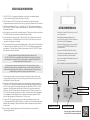
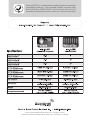
SANTA ROSA, CALIFORNIA
ICG-30 LP / ICG-30 NG INSTRUCTIONS
ICG-30 LP AND ICG-30 NG INTRODUCTION
Important Warnings and Cautions
Sentinel Intelligent Carbon Dioxide Generator
Read all instructions before installation and usage.
Save these instructions.
There are two different ICG-30 units, one is used for
Propane (ICG-30LP) and one is used for Natural Gas (ICG-30NG).
Below are the differences between the two units. Make sure you have
selected the correct unit and are using the matching fuel supply.
• For safety, it is recommended to always use a Sentinel Co2 monitor/controller
with the unit to measure current Co2 gas levels in the environment. Levels
over 2,000PPM should be avoided.
• Mount unit securely in a hanging position using the hardware provided. Maintain a minimum of 20” of clearance on all sides of the unit. DO NOT
PLACE UNIT ON GROUND / TABLE ETC.
• NG/LP gases are dangerous – Check all fittings by spraying with soapy water
before operating unit
• If gas is smelled, immediately unplug unit and ventilate the area. Check all
connections again.
• Always disconnect power to the unit before using foggers or bug bombs.
• Unit gets extremely hot when in operation. To prevent burns, do not touch the
unit. Do not allow flammable objects to come into contact with the unit.
• This unit shall not be exposed to dripping, splashing or spraying of liquids.
Protect unit from vapors, foggers etc.
• Clean unit with clean dry cloth, no oils or solvents
• Do not put paperclips, tools etc inside unit openings or receptacles. Possible
fire, shock or death may occur.
• Verify power source prior to connecting unit to power source and/or CO2
controller or timer
• Use only Sentinel supplied power supply to operate the unit. Use of any other
power supply will void warranty, and could cause a possible safety hazard.
• Protect any power cords from being walked on, pinched or crushed
• Protect any gas supply hoses from being walked on, pinched or crushed
• All brass fittings are flare fittings and self-sealing. Do not use Teflon tape on
gas connections.
• Unit is to be used within defined environmental parameters
• Use caution when operating in high humidity environments
• This unit contains no user-serviceable parts. Do not attempt to service this
product. Breaking any warranty seal will void warranty.
WARNING: Installation and connection of gas lines must be in
compliance with local and national building codes.
2
ICG-30LP: Liquid Propane, otherwise
known as LP or Propane, is stored in
pressurized tanks of varying sizes. The gas exiting the pressurized tank
must first be regulated to a very low
pressure before it enters the ICG-30. The standard for measuring the low
pressure is inches of water column
or Inch /WC. The ICG-30LP operates
at 11” WC, or about 1/2 PSI (2.8 kPa). The LP regulator provided with the
unit MUST be used unless it is verified
that the propane gas supply is already
regulated to 11” WC. The provided LP
regulator is designed to connect directly to portable LP tanks. It also has
a built-in safety function that limits
the flow of gas to a very low level in
the event of a large gas leak.
ICG-30NG: Natural Gas, otherwise
known as NG, is piped directly into
homes and businesses from an extensive pipeline system. The gas supply
entering the building can vary from
very low pressure (less than 1/4 PSI)
to over 5 PSI. The NG provided to the
ICG-30NG must first be regulated to
a very low pressure before it enters
the unit. The standard for measuring
the low pressure is inches of water
column or Inch /WC. The ICG-30NG
operates at 4.5” WC, or about 1/4 PSI
(1.15 kPa). The NG regulator provided
with the unit MUST be used unless it
is verified that the natural gas supply
is already regulated to 4.5” WC.
Once the NG gas is regulated down to
the correct pressure, it enters the unit
and flows through the solenoid valves
and the proprietary Sentinel stainless
steel burner assembly. The Sentinel
burner assembly is designed to be the
most efficient, cleanest burning CO2
generator available to today’s gardeners. It is the ONLY CO2 generator
burner we are aware of with a low NOX
design. The 3 stage design allows the
ICG-30NG to have a Co2 output of 9,
18 and 27 cu ft / hour. These modes
will create 9,000 , 18,000 and 27,000
BTU / hr or heat, and a large amount
of water vapor.
Once the LP gas is regulated down to
the correct pressure, it enters the unit
and flows through solenoid valves and
the proprietary Sentinel stainless steel
burner assembly. The Sentinel burner
assembly is designed to be the most
efficient, cleanest burning CO2 generator available to today’s gardeners.
It is the ONLY CO2 generator burner
we are aware of with a low NOX design. The 3 stage design allows the
ICG-30LP to have a Co2 output of
10.6, 21.2 and 31.8 cu ft / hour. These
modes will create 9,000 , 18,000 and
27,000 BTU / hr or heat, and a large
amount of water vapor.
ANY QUESTIONS...
Consult a licensed installer or contact Sentinel technical support
3
INITIAL INSTALLATION INSTRUCTIONS
1. T
he ICG-30 LP/NG is designed to hang from a ceiling joist or overhead support. It comes with two eyebolts, hooks and sections of chain.
2. D
O NOT place the ICG-30 LP/NG on top of something like a table to operate it. The generator requires a free flow of air coming in through the bottom of the enclosure.
3. T
he chains provided are 20” long. A minimum of 20” must be maintained between
the ICG-30 LP/NG and any walls or other obstructions. Take care to mount away from
flammable materials.
GETTING TO KNOW YOUR ICG-30
4. I nstall the two screw hooks into a suitable supports. The chains are then secured to the
ICG-30 LP/NG and the screw hooks with the included S hooks.
•Variable multi-mode CO2 outputs up to over 31
cubic feet per hour
5. E
nsure that the unit is hanging level. The ICG-30 LP/NG is designed with an anti-tip
over safety feature. In the event that the ICG-30 LP/NG is not level or tips over, the
gas supply and ignition are disabled.
•New Sentinel proprietary stainless steel, low-NOX burner assembly is cleaner and more
efficient than ANY CO2 generator
6. T
he gas connection fittings must be tightened properly. The supplied 12 foot (4m) hose
is connected from the flare fitting on the ICG-30 LP / NG to the provided appropriate
gas regulator. The flare fitting is located on the bottom of the ICG-30 LP/NG. Secure
the connection with two wrenches.
•Sentinel Intelligent ignition and control module
eliminates open pilot flames and provides for
maximum safety
•Tip-over switch automatically shuts off unit
•Advanced, multi-stage solenoid valve provides
consistent operation and redundant safety
Take care when attaching and tightening the brass flare fittings. All ICG-30 LP/NG units are checked and certified from the factory to not have
cross-threaded or stripped fittings. Cross threaded or stripped fittings ARE NOT
covered under Sentinel warranty terms.
•Unit comes complete with appropriate gas valve
and hose assembly
•RoHS compliant for environmental friendliness
The brass flare connection underneath the ICG-30 can be difficult to get to.
Please be patient. It has been designed this way to protect the fitting inside the
steel case during shipping from the factory, and moving around in the grow room,
greenhouse or garden during cleaning and maintenance.
7. O
nce the gas connections are secured, pressurize the gas line and check for leaks
using the soapy water. Spray the water onto the gas connection fittings and look for
any bubbles. Re-secure if necessary.
8. A
fter the ICG-30 has been hung properly, and gas connections have been checked,
test fire the unit. Plug the low voltage connection of supplied 24v power adaptor into
the ICG-30, and plug the high voltage connection into any NEMA 5-15 120v / 60Hz
receptacle. Switch the power button to the ON position. Press the mode button
(M/S) until the “M” (Manual mode) is displayed on the ICG-30 status screen. The
ICG-30 will turn on and ignite the burner. Note: Sometimes during initial installation
(and subsequent LP tank changes) several attempts are need to ignite the ICG-30
due to air being purged out of the gas lines. This is normal.
9. O
nce the ICG-30 is operating properly, press the output buttons up or down to
cycle through the different output settings. It is normal for 5-10 seconds to take place
between output changes. Note how the burner pattern changes during the different
output modes.
10. If everything is operating properly, switch off the power button and proceed to
“Operating Instructions”.
4
LED STATUS DISPLAY
POWER BUTTON
OUTPUT UP
OUTPUT DOWN
POWER INPUT PORT
MODE SWITCH (M/S)
Scan this code to learn more about the
Sentinel ICG-30 on your smart phone!
5
OPERATING INSTRUCTIONS
A. Operation in the S.I.C.E. (Sentinel Intelligent CO2 Enrichment ™ ) mode
Your new ICG-30 series generator is the most advanced CO2 generator available
on the market today. It incorporates the proprietary S.I.C.E. – Sentinel Intelligent
CO2 Enrichment – communication and control components and programming that are unique to Sentinel. This patent pending system allows for communications
between Sentinel S.I.C.E series products, providing a level of control never before
seen in your greenhouse, garden or grow room. The system works by a Sentinel S.I.C.E. series controller, such as the Sentinel CPPM-4i
or Sentinel CHHC-4i, measuring and monitoring your growing environment. As the
atmospheric CO2 levels change, the controller will tell the ICG series generator to
increase output, decrease output, or go into idle mode…all computer controlled. In this way, a growing environment that has very low Co2 levels, such as the start
of the day or after a ventilation cycle, can be rapidly brought back up to optimal
growing conditions. As the optimal conditions are reached, the S.I.C.E. system can
decrease Co2 output, making sure that the user defined optimal level is not overshot.
As needed, the growing environment can be “topped off” with CO2 enrichment on a
lower output setting, allowing for air conditioners and dehumidifiers to better deal
with the heat and moisture loads associated with Co2 enrichment and maintaining
more steady temperature and rH levels.
1. F ollow the Initial Installation Instructions for your ICG series generator, and your
S.I.C.E. Series Co2 controller.
2. P
lug the ICG-30 power supply into an electrical outlet that will always be
energized. DO NOT plug the power supply for the ICG-30 into the CO2 controller.
3. Turn the power switch for the ICG-30 to the ON position.
4. P
ress the MODE button (S/M) until “S” shows on the ICG-30 LED system
status screen.
5. Turn the power switch to the OFF position.
6. C
onnect the appropriate Sentinel S.I.C.E. shielded communication cable between
the ICG-30 and the Sentinel S.I.C.E. CO2 controller. S.I.C.E. shielded communications cables are available from your preferred retailer,
or from www.growgps.com/store. Sentinel S.I.C.E shielded communications
cables are available in 5 meter ( part# SICEcbl5), 10 meter ( part# SICEcbl10),
25 meter ( part# SICEcbl25), and 50 meter ( part# SICEcbl50) lengths. These are NOT standard Ethernet cables. They are shielded to reduce interference
coming from digital ballasts, and are specially coated to not allow moisture inside.
The use of standard Ethernet cables in NOT recommended, and any harm that
comes from the use of non-Sentinel approved cables VOIDS any and all warranties.
6
OPERATING INSTRUCTIONS (continued)
The special coatings on these cables makes them less-flexible than
standard Ethernet cables. They are not intended to be highly flexible.
It is recommended after installation that the cables are affixed securely
to the walls or ceilings of your greenhouse or grow room in a manner
that makes sure the cables are not pinched or crushed.
7. S
et the Sentinel S.I.C.E series CO2 controller to the preferred levels using
the “Sentinel Intelligence” setting as outlined in the user manual of the S.I.C.E.
series controller.
8. Turn the power switch to the ON position.
9. Enjoy the most advanced CO2 enrichment operation available!
B. Operation in the manual setting enrichment mode
While the ICG-30 series CO2 generators have been designed with advanced
communication and control componentry for ideal operation using the proprietary
S.I.C.E. system, the ICG-30 can work with any previous Sentinel brand CO2
controllers as well as other manufacturer offerings. And the best part is you can
always upgrade to a Sentinel S.I.C.E. series controller in the future!
1. F ollow the Initial Installation Instructions for your ICG series generator and the
appropriate instructions for your existing CO2 controller.
2. Plug the ICG-30 power supply into the appropriate CO2 controller receptacle.
3. Turn the power switch for the ICG-30 to the ON position.
4. Press the MODE button (S/M) until “M” shows on the ICG-30 LED display screen.
5. P
ress the output buttons (# or $) to select between output setting #1, #2, or #3
as shown on the ICG-30 LED system status screen. As a very basic starting point, growing environments under 3,0003 feet should be
set to output level 1, growing environments from 3,0003 to 7,5003 feet should be
set to output level #2, and from 7,5003 feet and larger set to output level 3.
If it is taking too long to reach your desired set point, consider using
the next higher setting. If you are consistently over-shooting your
desired set point, consider using the next lower setting.
Remember, the most precise control available is obtained using a Sentinel
S.I.C.E. series CO2 controller in conjunction with the ICG-30 series generator.
7
Sentinel GPS Inc. is dedicated to producing environmentally
sustainable products. The enclosed product complies with
RoHS Directive (2002/95/EC) that restricts the use of 6
hazardous substances such as mercury, cadmium and lead.
©2015 Sentinel Global Product Solutions Inc. All rights reserved. Distributed by Sentinel Global Product Solutions Inc., Santa Rosa, CA 95403