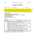
1
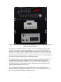
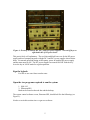
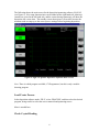
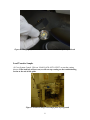
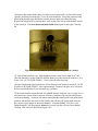
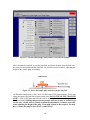
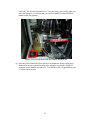
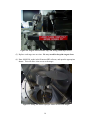
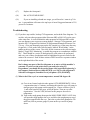
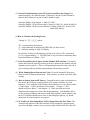
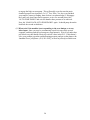
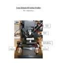
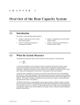
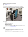
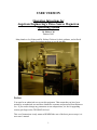
USER VERSION
Operating Intructions for
Angstrom Engineering’s Three Source Magnetron
Sputtering System
By Suberr Chi
Summer 2002
Many thanks to Joe Palmer and Dr. Helena Gleskova for their guidance, and to David
Inglis for teaching me how to use the machine.
Preface
You must be an authorized user to use this equipment. That means that you have been
trained by an authorized user and have obtained a username and password from Helena or
Joe. If you need to change any parameters or run codepositions, see Joe for upgrading
security privileges to the TECHNICIAN level.
This set of instructions is only meant to REMIND the user of the basic process steps, it is
not a user’s manual.
1
Take a minute to look over the equipment on the front of the sputtering machine- you
should see the Granville-Phillips Ion Controller and Pressure Gauges, Type 247 4channel readout switches for measuring Argon gas flow, Load Lock pressure gauge, Cryo
pump temperature gauge (Kelvin), main chamber temperature and sample plate
temperature gauge (Celsius), and the RF power supply and 2 DC power supplies.
Familiarize yourself with their operation. For detailed information, please refer to the
technical manuals on the sputtering system computer provided by Angstrom Engineering.
Figure 1: Sputtering controls and devices
2
Figure 2: Closeup of (from top panel to bottom panel); Type 247, Load Lock pressure
gauge, Cryo-pump monitor.
The Type 247 4-channel readout box is simply a device for controlling Argon gas flow.
As many as four different types of sputtering gases can be used for the four channelshowever, only Argon is currently being used due to its cheap price, large ion mass, and
availability. To engage gas flow, make sure that the main power switch is ON, and that
channel 2 (Argon) is also turned on. It is currently set to12.18 sccm. More on Argon gas
flow operation will be discussed in the section on sputtering.
The Load Lock Pressure Gauge indicates the pressure inside the load lock located at the
left hand side of the machine. During the ‘AUTO LOAD LOCK PUMP DOWN’
sequence, the load lock will first decrease in pressure to ~ 80 mTorr setpoint with the
rough pump, then switch to the high vacuum to pump down to below the range of the
gauge. It will read between 0 and 3 Torr.
The Cryo Pump Monitor indicates the temperature of the cryo pump in Kelvin. For
normal operation, the temperature should be 11 or 12 K. Above 20 and the pump will
have to be re-generated, which may take up to 3 hours.
3
Figure 3: Closeup of; Granville-Phillips pressure gauges, and main chamber
temperature display. Main chamber pressure is given in the display labeled IG.
The Granville-Phillips Pressure Gauge indicates, most importantly, the pressure inside
the main chamber. In order to sputter, the main chamber pressure must be < 5 x 10⁻⁶
Torr. There are three pressure readouts listed on the lower panel, and are labeled as IG,
A, and B. IG is the most important, and displays the main chamber pressure when the
pressure is in the range of the ion gauge. A indicates the chamber pressure when the
pressure is between 780 Torr and ~10 mTorr. B gives the pressure within the cryopump
itself, but the gauge has the same range as A.
The heater temperature in Celcius is the number in red. The green number is the setpoint.
To change the setpoint press and hold the arrow keys. This temperature setpoint will be
displayed in green. The sample surface will not be as hot as the heaters themselves. A
calibration curve can be found in this manual and on the front of the machine.
4
Figure 4: From top to bottom; RF, DC1, and DC2 power supplies. Note on/off keys on
right hand side of DC power boxes.
This part is fairly self-explanatory. The two blue and black boxes are for the RF power
supply and its accompanying tuner with the DC1 and DC2 power supplies shown below
those. For normal operation during an RF sputter, power to both the RF power supply
and the tuner must be ON. The DC power supplies are turned ON/OFF with the keyleave the key in LOCK mode for regular operation.
Sign the logbook
Feel free to use extra lines to make notes.
Open the two programs required to run the system
1. SQS-142
2. Princeton.SR2
Both can be found on the task bar and the desktop
The system control software screen, Princeton.SR2, should look like the following (see
Figure 5):
Need to re-write this section since we got new software.
5
The following shows the main screen for the deposition/sputtering software, SQS-142,
(see Figure 6). Key ramp characteristics can be added on the right hand side, start/stop
controls are given on the left hand side, and the center (during sputtering) will show the
deposition rate versus time. The standby screen shows power versus time because the
machine needs to ramp up to the correct power settings before beginning deposition.
Figure 6: SQS-142 Sputter Deposition Software main screen.
Note: There is a third program available, CX Programmer, but this is only a troubleshooting program.
Load/Create Process
In the deposition software under ‘FILE’, select ‘PROCESS’, and then select the desired
program, being careful to select the correct material and sputtering source.
More is needed here.
Check Crystal Reading
6
Under ‘VIEW’ select ‘SENSOR READINGS’. A crystal at 80% will function for about
4μm of deposition.
Sensor 1
Sensor 2
Sensor 3
Sensor 4
RF Source
DC 1
DC2
Near sample plate
You can see what materials are on each source by clicking the MATERIALS LIST button
located on the right hand side of the System Control screen.
Figure 7: Materials List tab in Princeton.SR2.
If a crystal needs to be changed, then see Joe or Helena for permission to perform this
maintenance. To perform this procedure, you need to hit ‘AUTO VENT’ and wait 10
minutes for the main chamber to vent. Remove the plate holding the crystal, and insert
the new crystals with the etched side facing up, and the completely gold side facing
down. Re-insert the plate into the holder. Upon initial crystal replacement, the crystal
may give a negative reading for thickness and/or deposition rate. This will zero out and
give the correct reading once sputtering is started. Be careful loading the crystals
because they are brittle and prone to cracking. When you’re done loading the crystal,
click on ‘AUTO PUMP DOWN’ to pump the main chamber down to base pressure.
7
Figure 8: Changing crystal sensors- note the correct orientation of the crystal head.
Load/Transfer Sample
(1) Go to System Control. Click on ‘LOAD LOCK AUTO VENT’ to start the venting
process. If the load lock will not vent, or will not stop venting see the troubleshooting
section at the end of this guide.
Figure 9: Load lock image with sample plate in foreground.
8
(2) Remove the sample holder plate. Set it down on a clean surface, or the hollow metal
cylinder, and load your sample(s). Cover all of the bolt holes, except the outermost ring.
Metal going through open bolt holes coats the heaters and lowers their efficiency.
Replace the sample plate so that the three wells on the plate line up with the three screws
in the load lock. The three horizontal bolts heads should point to the right. Close the
lid.
Figure 10: Note orientation of three bolts pointing into the chamber
(3) Turn off the load lock vent. Main chamber pressure must be less than 5x10⁻⁶ torr
(first line labeled IG on the Granville Phillips display) to pump down the load lock. If it
is not, click ‘AUTO PUMP DOWN’. If it is, proceed to the next step
.
(4) Once base pressure has been achieved close the top of the load lock and click ‘AUTO
LOAD LOCK PUMP DOWN’. After approximately 2 minutes, the gate valve will open.
Refer to troubleshooting if you encounter any problems.
(5) Move the transfer arm to the load lock ONLY after the load lock valve is open. If it is
moved this time (in an effort to increase efficiency) machine will only jam and prevent
you from sputtering. An alarm will appear noting that the transfer arm is not in the home
position, and the blue interlock for the transfer arm will turn off- ignore both until you
have secured your sample in the main chamber! A button flashing ‘YES, have you
finished transfer” will also appear- do not hit yes until you have secured your sample!
Clicking YES will close the load lock gate valve.
9
Figure 11: Do not acknowledge until you have secured your sample!
Move the transfer arm fork over to the load lock, and lower the plate onto the fork with
the screw located underneath the load lock. Be careful to sense resistance, adjusting the
height of the sample plate accordingly.
Figure 12: Lower the sample plate onto the transfer arm fork.
(6) When the sample plate is free, move it to the center of the main chamber. Lower and
rotate the copper plug into the receptor on the plate. DO NOT BEND THE TRANSFER
ARM!!!! Pick up the plate and move the fork to its home position, again being careful to
feel for resistance. During this process the transfer fork can be bent or broken if you
are not very careful. Always visually confirm the adjustments you make, especially
when adjusting the height of the plug. If the plug is stuck in the receptor, you may
have to rotate the plug to move it free- rotate slowly!
10
Figure 13: Lower the spindle into the shaft, rotate it right, then raise it to lock the
sample plate in place. Withdraw transfer arm to home position when done.
The knob boxed in yellow will raise/lower ONLY the copper plug itself, and the knob
boxed in blue will rotate the copper plug. The red boxed one is broken.
Raise the sample plate using the yellow handle until the sample plate edge is just above
the bottom of the heating stage shroud. Check using the topmost knob (blue) that the
sample plate rotates freely.
Figure 14: Knobs for raising, lowering, rotating the copper plug into place.
11
Click ‘yes’ once you have finished your transfer and the transfer arm is in the home
position. The load lock gate valve will close at this point.
Figure 15: After the transfer is complete, the transfer arm must be moved into the
home position, and sensor (boxed) must be pushed back all the way.
Figure 16: After the transfer arm is in the home position, acknowledge it, and click
‘YES’. The load lock gate will close and the system is almost ready for sputtering.
12
Sputter
(1) Turn on the appropriate power supply. If using the RF Source, turn on power for
BOTH blue boxes, the RFX power supply and ATX remote controller.
(2) Turn on the MKS 247 mass flow controller to initiate the Argon flow- a green LED
will turn on.
Figure 17: Turn Channel 1 on to initiate Argon flow into the main chamber.
(3) Close the shutter on the main viewing window port, and turn off the snake light.
Figure 18: Blue-colored sputtered atoms during a Cobalt deposition on DC1.
(4) In the SQS-142 Deposition software, click ‘START PROCESS’.
If an alarm is set off that says ‘Plasma Did Not Strike’
- Acknowledge it
- Click the RESET button on the screen
- Click AUTO PUMP DOWN to restart the cryo pump
- Check that the power supply is on and in remote operation
- Increase sputtering power/rate
13
-
Check that all interlocks are correc
When finished
(5) Turn off the power supply, and turn off the Argon flow.
Unload Sample
(1) Click AUTO LOAD LOCK PUMP DOWN, and wait for load lock gate valve to
open.
(2) Make sure that the 3 bolts are pointed to the right- towards the transfer arm. If they
are not, rotate them so that they are! Follow the loading process in reverse, and once the
transfer arm is returned to its home positions, click ‘yes’ that you have finished your
transfer.
(3) Vent the load lock.
(4) Unload your sample. Replace the plate, and click auto load lock pump down.
Stop the load lock pump down by clicking again.
Click Auto Pump Down to pump the main chamber and stop the load lock pump
sequence.
Sign out
Right click and exit the control software. To exit the deposition software, Select file ->
exit, and hit ‘Enter’.
Sign the log book
Changing Targets
When you want to insert new targets into the sputterer, see Joe or Helena for permission
before you do the following:
(1) Hit ‘AUTO-VENT’- venting should take 10 minutes.
(2) While waiting for the main chamber to vent, remove the front panel.
(3) Once completely vented, lower the bottom flange of the main chamber by
pressing retract on the lower hydraulic control box. The box is in the back left
corner of the machine. The bottom flange can also be moved via the on-screen
controls, or the controls inside the sputterer (once the front panel has been
14
removed.) The on-screen buttons have a 2 second delay, so be careful when you
lower the chamber- it is advised that you use the extend(UP)/retract(DOWN)
buttons inside the sputterer.
Figure 19: Lower the hoist with the controls boxed in red.
(4) Once the lower chamber has been moved to its minimum (being careful not to
dislocate the power cords and cooling tubes along the way down), SLOWLY
swing the lower chamber towards you. You should see the 3 targets/holders and
3 Crystal sensor mounts.
15
Figure 20: Targets lowered all the way, and swung outward for access.
(5) Replace each target one at a time. Be very careful to keep the targets clean.
(6) Enter MANUAL mode in the Princeton.SR2 software, and open the appropriate
shutter. This will allow clear access to the target.
Figure 21: Swing the shutter open for easier access to the target.
16
(7) Unscrew the 3 bolts holding the target skirt up. Slide the skirt down to expose the
target.
(8) Use a flat screwdriver to lever and remove the target. Place the target face down
on a clean texwipe and wrap it up with the texwipe. Use tape to secure the wipe
and write on the texwipe what type of metal it is. Do not write on the texwipe that
covers the front surface of the target as ink will wick through and possibly
contaminate the target.
(9) Apply new silver thermal grease to the target holder magnet, spreading it evenly
with a Q-tip. The layer should be evenly applied and thin enough to see the
copper color behind it.
Figure 22: Apply silver thermal grease around target magnet holder.
(10)
Grasping the target firmly and securely lower the new target onto the
magnet- be careful, it will jump out of your hand.
(11)
Re-tighten the 3 bolts, Do not over tighten. Be careful not to change the
angle of the gun.
(12)
Close the respective shutter from the screen in Princeton.SR2, and change
the respective metal on the ‘MATERIALS LIST’.
(13)
Repeat as necessary for the other targets.
(14)
Use a razor blade to scrape off any metal peeling from within the lower
chamber. Use the cleanroom vacuum to remove the scrapings.
(15)
Change any crystal sensors as needed. To remove the crystal sensor,
simply remove the crystal holder, discard the old crystal, and insert the new
crystal with the gold side facing downwards. Re-insert the crystal holder.
(NOTE: the crystals may also be changed via access through the upper chamber.)
(16)
Swivel the lower chamber back into the sputterer, and raise it to just ‘kiss’
the main chamber.
17
(17)
Replace the front panel.
(18)
Hit ‘AUTO-PUMP-DOWN’.
(19)
If you are installing a brand new target, you will need to “warm it up” for
use. A precondition will remove the top layer of metal. Suggested amount is 35%
power for 5 minutes.
Troubleshooting
(1) If you have any trouble, load up CX Programmer, and read the flow diagrams. To
use this, only one other program (either Princeton.SR2 or SQS-142) can be open
at the same time. It is advised that the other program be Princeton.SR2 so that
you can diagnose your on-screen system changes. Start up CX Programmer, and
open the file C:\Program Files\Omron\CX-Programmer\Examples\Princeton Ver.
2~6.cxp. (You can alternately open up the file, tutorial.cxp, in the same directory
for practice.) Click on the little yellow triangle, labeled ‘Work Online’, in the
taskbar at the top of the screen. Also click on the icon next to the yellow triangle,
labeled ‘Toggle PLC Monitoring’, to enable the program to communicate with the
PLC. There should be a series of checkpoints for each action to be performed,
and every one of these checkpoints must be highlighted in green in order for the
action to be executed. Each of those actions will be located in a separate window
on the right hand side of the screen.
Don’t change any part of the flow diagrams so as not to void the machine’s
warranty. If you are at the point where you need to be using CX
Programmer, you should also be on the phone with Angstrom Engineering’s
tech support (Andrew Bass at (800) 695-8270- ext. 110) or with Angstrom’s
Software tech support (Jonathon Sweet [cell phone: (519) 501-8385]).
(2) What to do if the cryo is at room temperature, around 300 degrees K:
(a) Go to Auto Control, and select the option AUTO REGENERATE. Select
a regeneration time of 1 minute, and during this time the cryo will pump in
nitrogen gas to help pump out the trapped gas. Choose a failure cycle of
1, and at the bottom of the page, select the option ‘Turn on cryo after
regeneration.’ Now hit YES, and wait for the pump to decrease in
temperature.
(b) Turn on the rough pump, then open the MAIN FORE LINE VALVE- this
will open the rough pump to the cryo, and allow the rough pump to expel
the gases trapped inside the cryo. Once the cryo has been pumped to 150
milliTorr (look at pressure gauge B), turn on the cryo and let it pump
down.
18
(3) General Troubleshooting on the GP Convectrons/Micro-Ion Gauges: For
normal operation, on each convectron: Filament #1 on pins #3 and 4 should be
shorted, and Filament #2 on pins #4 and 5 should be open.
Granville-Phillips Tech Support: 1- (800) 367-4887
Granville-Phillips 355 Micro-Ion Gauge: Catalog #355001-YG, Serial #01080314
Granville-Phillips 358 Micro-Ion Controller: Catalog #358001-T1, Serial #1786,
Model #00, Date E1
(6) How to Calculate the Tooling Factor:
Tooling % = TFn * (Tm/Tx) where
TFn = present tooling factor guess
Tm = actual thickness as measured by DEKTAK (or other device)
Tx = thickness reading on SQS-142 display.
Re-calculate Tooling % and substitute it as the next value for TFn- repeat until
(Tm/Tx) is approximately = 1. The DEKTAK is only accurate for measuring films
beyond a thickness of 300nm = 3 kA.
(7) If the Front/Side Panel is Open, and the Machine Will Not Run: You need to
replace the front/side panel by screwing it back in, otherwise the machine will not
respond to any key presses. This is a safeguard implemented to reduce the risk of
your crawling under the machine and potentially electrocuting yourself.
(8) When Pumping Down from an Auto Vent: Do not be alarmed if the process
takes between 45 minutes and an hour. This is normal- go check your email while
waiting.
(9) How to Sputter from an RF Source: First and foremost, make sure that the two
blue boxes, the RFX power supply and the ATX remote controller, are both
turned on. Next, under the Source/Sensor tab in Edit Process, select Source Index
= 1 and Output = 1 (DC2 should use Source Index = 2, Output = 1, DC1
should use Source Index = 2 and Output = 2). Make sure that power and
deposition rate settings are correct, then begin sputtering. You should be able to
see the opening of shutters and powers on the Stata System Control software, and
the ATX controller should have a series of green displays light up, e.g. Interlk
means that all of the Interlocks are in place.
(10)If ‘Load Lock Auto Pump Down’ Fails to Pump Down the First Time: The
characteristic behavior is that the load lock will be roughed to a pressure point
just above the high vacuum crossover point, usually around 160 mTorr, then fail
19
to engage the high vacuum pump. This will usually occur because the main
chamber pressure has risen above 5 x 10⁻⁶ Torr. If the ‘Yes- have you finished
your transfer’ button is flashing, then click on it to acknowledge it. Disengage
the Load Lock Auto Pump Down sequence, wait a few seconds, then click
‘AUTO PUMP DOWN’ and wait for chamber base pressure to be achieved.
Now, hit ‘LOAD LOCK AUTO PUMP DOWN’ again. It should pump down the
load lock the second or third time.
(11)What to do if the machine is not responding to the reset button, or to any
other input: Since you may be encountering a stuck bit, turn off the system
computer, and then push the red emergency stop button in. Wait 10 seconds, then
pull it back out- this should effectively reset all values in the PLC. If this doesn’t
solve your problem, open the troubleshooting program, and get on the phone with
Jonathon Sweet [cell phone: (519) 501-8385], or email at [email protected].
20