1
1/10/2012
363-S USER’S MANUAL
Revision 1.6
i
Table of Contents
TABLE OF CONTENTS
Introduction / using this manual ............................................................................................................................5
Safety ......................................................................................................................................................................6
READ BEFORE OPERATING THIS MACHINE ....................................................................................................6
Observe and Obey All Warnings Listed Below ...............................................................................................7
Machine Information ..............................................................................................................................................9
General Machine Specifications ....................................................................................................................9
Machine Requirements ...............................................................................................................................10
Operating Conditions...................................................................................................................................10
Spindle Specifications ..................................................................................................................................11
Software introduction ..........................................................................................................................................13
Touchscreen Alignment Procedure .............................................................................................................14
On-Screen Keyboard ....................................................................................................................................15
Menu Buttons ..............................................................................................................................................16
Panels ..........................................................................................................................................................21
Dashboard ............................................................................................................................................21
Control Panel ........................................................................................................................................22
View Panel ............................................................................................................................................29
Input Panel ...........................................................................................................................................37
Hardware Introduction .........................................................................................................................................44
Coordinate Axes ..........................................................................................................................................44
Pallet and Spindle Mounting .......................................................................................................................45
Work Piece Mounting System .....................................................................................................................46
Spindle Introduction ....................................................................................................................................48
40 000 (NR-5041E ATC) & 50 000 (NR40-5100 ATC) RPM Electric Motor Driven Spindles with
Automatic Tool Changing Capability (pictured in Figure 5.4) ...............................................................48
50 000 (IBAG - HF45A60CP) RPM Electric Motor Driven Spindles with Automatic Tool Changing
Capability ..............................................................................................................................................48
80 000 RPM Electric Motor Driven Spindles (NRA-5080) .....................................................................48
160 000 RPM Air Turbine-Air Bearing Spindle (ABS-1600) ...................................................................48
Front of the Machine ...................................................................................................................................51
Handheld Pendant .......................................................................................................................................52
Machine Regulators .....................................................................................................................................53
Back of the Machine ....................................................................................................................................55
Installation / transportation .................................................................................................................................57
Installation ...................................................................................................................................................57
Transportation .............................................................................................................................................58
1
Table of Contents
September 2011
i
Table of Contents
Pallet Jack or Fork Lift ...........................................................................................................................58
Operation .............................................................................................................................................................59
Power-On Procedure ...................................................................................................................................59
Power-Down Procedure ..............................................................................................................................59
Software Startup and Homing the Motors ..................................................................................................59
Spindle Operation ........................................................................................................................................60
Before Enabling the Spindle .................................................................................................................60
Starting the Spindle ..............................................................................................................................60
Changing the Spindle Speed .................................................................................................................61
Disabling the Spindle ............................................................................................................................61
Tool Changing – Manual Collet – 80 000 RPM Electric/Air Bearing.............................................................62
Tool Installation ....................................................................................................................................62
Tool Removal ........................................................................................................................................63
Tool Changing–Manual Collet–160 000 RPM Air Turbine/Air Bearing ........................................................64
Tool Installation (Figure 7.6).................................................................................................................64
Tool Removal (Figure 7.6).....................................................................................................................65
Tool Changing – Automatic Collet ...............................................................................................................66
Tool Installation ....................................................................................................................................66
Tool Removal ........................................................................................................................................67
Tool Changing - Automatic Tool Changer ....................................................................................................68
Manual Operation Mode ......................................................................................................................68
Operation in an NC program ................................................................................................................71
Tool Changer Alignment .......................................................................................................................71
Tool Collar Setting using Bohan Tool Setter .........................................................................................73
Tool Collar Setting using Two-Piece Setting System.............................................................................74
Tool Sensing – G120 Cycle ...........................................................................................................................75
Syntax and Parameters.........................................................................................................................75
Length Measurement Examples: ..........................................................................................................75
Calculation of X and Z parameters: ......................................................................................................75
Auto-Sensing Multiple Tools for a Job using the Microlution mMT Control Software.........................75
Manual Operation Mode ......................................................................................................................76
Implementation in an NC Program .......................................................................................................76
Z-Axis Fixture Probing – G123 Cycle ............................................................................................................77
Syntax and Parameters.........................................................................................................................77
Fixture Probing Example.......................................................................................................................77
Workpiece Probing ......................................................................................................................................78
X Y Z single surface measurement (G65 P9811) ...................................................................................79
2
Table of Contents
September 2011
i
Table of Contents
Pallet ID function (G65 P9809) .............................................................................................................81
Error code index table ..........................................................................................................................84
Example ................................................................................................................................................85
Subroutines and Macro Program Calls ........................................................................................................87
Setup and Organization ........................................................................................................................87
Syntax and Parameters.........................................................................................................................87
Subprogram Parameter Variables ........................................................................................................88
Subprogram Example ...........................................................................................................................89
Data Setting .................................................................................................................................................90
Data Setting Group Descriptions ..........................................................................................................90
Data Setting Examples ..........................................................................................................................90
Conditional Statements ...............................................................................................................................92
If ({condition}) {action} .........................................................................................................................92
While ({condition}) {action} ..................................................................................................................93
GOTO{data} ..........................................................................................................................................93
Pallet Changing ............................................................................................................................................95
Removing the pallet .............................................................................................................................96
Installing the pallet ...............................................................................................................................97
Tool Setting - Camera ..................................................................................................................................98
Using the Handheld Pendant .....................................................................................................................104
Executing a Program ..................................................................................................................................105
Manually Running a Program by Using the Terminal Panel ...............................................................105
Automatically Running a Program by Using the Combine Tab and the Program Tab ........................107
Part Offsets ................................................................................................................................................108
Save Current Location to a File ...........................................................................................................108
Recall Saved Location from a File .......................................................................................................109
Set Known Location as Program Origin ..............................................................................................109
Cleaning/Maintenance .......................................................................................................................................110
Cleaning .....................................................................................................................................................111
Maintenance..............................................................................................................................................113
Supported G and M Codes .................................................................................................................................116
Appendix a – Legacy / Custom Order .................................................................................................................129
Spindle Changing (Kinematic Mount Type) ...............................................................................................129
Removing the Spindle .........................................................................................................................129
Installing the Spindle ..........................................................................................................................130
Workpiece sensing ....................................................................................................................................130
Manual Operation Mode ....................................................................................................................131
3
Table of Contents
September 2011
i
Table of Contents
Operation in an NC Program ..............................................................................................................131
Spindle Control Unit ..................................................................................................................................133
Part Pattern Tab ........................................................................................................................................136
Creating a Part Pattern .......................................................................................................................138
Legacy Cleaning / Maintenance .................................................................................................................141
Laser Inspection (LT-9010 Confocal Laser Option Required) .....................................................................142
Scanning Using a Predefined Scanning Pattern ..................................................................................142
Scanning Using a User Defined Scanning Pattern ..............................................................................143
User I/O (option required) .........................................................................................................................145
Digital Inputs ......................................................................................................................................146
Digital Outputs ...................................................................................................................................146
Analog Inputs......................................................................................................................................146
Filtered PWM Analog Outputs ...........................................................................................................147
User Flags ...........................................................................................................................................147
4
Table of Contents
September 2011
I
Introduction / Using This Manual
INTRODUCTION / USING THIS MANUAL
Thank you for purchasing the Microlution, Inc. 363-S micro-milling machine tool. This instructional manual will
introduce the 363-S, its specifications, components, software, and other aspects of the machine.
Before operating the 363-S, this manual should be read thoroughly and in its entirety. After the manual has been
completely read, keep it as a reference for later use.
Please read this manual from beginning to end starting with the Safety section. Following the Safety section is the
Machine Information section with machine specifications, requirements, operating conditions, and other useful
information. Following the Machine Information section is the Software Introduction section. The Software
Introduction is where the machine software is introduced and all the buttons, functions, and windows are
explained.
Note: A step – by – step set of instructions for operating the machine and navigating the
software is located in the Operation section of this manual.
Following the Software Introduction is the Hardware Introduction. The Hardware Introduction introduces the
exterior components of the machine and their functionality. Next, the Installation / Transportation section
describes proper installation and transportation steps, precautions, and techniques. Following the Installation /
Transportation section is the Operations section. The Operations section provides step – by – step instructions for
operating the machine and using the software. Finally, the Cleaning / Maintenance section describes the correct
procedure for cleaning and maintaining the machine.
Note: The black highlighted titles differentiate sections. The grey highlighted titles breakup the
sections into sub-sections, and are therefore referred to as sub-sections. Underlined headings
within sub-sections are referred to as segments.
5
Introduction / Using This Manual
September 2011
II
Safety
SAFETY
R EAD B EFORE O PERATING T HIS M ACHINE
Only authorized personnel should work on this machine. Untrained personnel present a hazard to
themselves and the machine, and improper operation will void the warranty.
Check for damaged parts and tools before operating the machine. Any part or tool that is damaged
should be properly repaired or replaced by authorized personnel. Do not operate the machine if any
component does not appear to be functioning correctly. Contact your shop supervisor.
Use appropriate eye and ear protection while operating the machine. ANSI-approved impact safety
goggles and OSHA-approved ear protection are recommended to reduce the risks of sight damage
and hearing loss.
Do not operate the machine unless the protective lid is closed. Rotating cutting tools can cause
severe injury. When a program is running, the X,Y, and Z stages as well as the spindle can move
rapidly at any time in any direction.
The Emergency Stop button (also known as an Emergency Power Off button) is the large, circular red
switch located on the handheld pendant (see Hardware Introduction section). Pressing the
Emergency Stop button will shut off power to the X, Y, and Z stage motors as well as the spindle. Use
the Emergency Stop button only in emergencies to avoid crashing the machine.
All machine panels should be closed and secured at all times except during installation and servicing.
During installation and servicing, only qualified personnel should have access to the machine. When
power is supplied to the machine some components operate at high temperatures. Therefore,
extreme caution is required. Once the machine is installed, the control cabinet must be secured and
only opened by qualified service personnel.
DO NOT modify or alter this equipment in any way. If modifications are necessary, all such requests
must be handled by Microlution, Inc. Any modification or alteration of any Microlution milling
machine could lead to personal injury and/or mechanical damage and will void your warranty.
It is the machine supervisor’s responsibility to make certain that all who operate or service the
machine are thoroughly acquainted with the installation, operation, and safety instructions BEFORE
operating or servicing the machine.
This machine is automatically controlled and may start at any time.
This machine can cause bodily injury.
Do not operate with the protective lid open.
6
Safety
September 2011
II
Safety
Observe and Obey All Warnings Listed Below
Do not operate without proper training.
Personal Protective Equipment:
o Always wear safety goggles;
o Abrasion-resistant gloves are recommended when handling
sharp tools, workpieces and workpiece pallets. Caution must
be taken as gloves may become entangled in rotating or
moving parts within the machine.
The electrical power must meet the specifications in this manual.
Attempting to run the machine from any other source can cause
severe damage and will void the warranty.
DO NOT power up machine until after the installation is complete.
NEVER service the machine with the power connected.
Improperly fastened parts machined at high speeds/feeds may be
ejected and puncture the protective lid. Machining oversized or
marginally fastened parts is not safe.
The window in the protective lid must be replaced if damaged or
severely scratched - Replace damaged windows immediately.
Do not process toxic or flammable material. Deadly fumes can be
present. Consult material manufacturer for safe handling of material
by-products before processing.
The machining process may generate fine, dust-like swarf.
Depending on the workpiece material, appropriate care (for example
vacuum swarf removal) must be taken to properly handle the swarf.
Consult material manufacturer for additional information.
7
The machine must be periodically cleaned to remove residual swarf.
The user is responsible for establishing a cleaning process and
schedule, as required by material removal rates, workpiece material,
and other factors.
Safety
September 2011
II
Safety
8
Safety
September 2011
III
Machine Information
MACHINE INFORMATION
Warning: Read this section before operating machine! Failure to do
so can result in machine malfunction and/or operator injury.
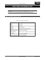
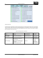
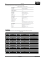
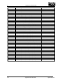
General Machine Specifications
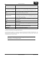
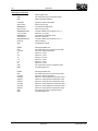
Table 3.1: General Machine Specifications
9
Height
135 cm [53"]
Width
71 cm [28"]
Depth
64 cm [25"]
Footprint
0.45 m [4.86 ft ]
Weight
340 kg [750 lbs] without accessories
Maximum Feed Rate
8000 mm/min [314.9 IPM]
Machine Travel
63 mm x 63 mm x 63 mm [2.48" x 2.48" x 2.48"]
Resolution
0.05 microns [0.0000008"]
Positioning Accuracy
2.0 microns [0.00008"]
2
2
Machine Information
September 2011
III
Machine Information
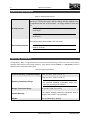
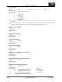
Machine Requirements
Table 3.2: Machine Requirements
Minimum of 170 liters/min @ 0.7 MPa [6 CFM @ 100 PSI] supplied to the
air regulator at the rear of the machine. Air supply should be clean and
dry.
NOTE: Check that the air regulator at the rear of the machine is
set to 90 psi.
Air Requirements
NOTE: Air consumption will vary based on spindle selection and
accessories.
The machine plugs into a standard 110 VAC outlet.
Electrical Requirements
NOTE: The machine requires 20 Amps. Ensure the circuit is
rated for 20 Amps.
Operating Conditions
The Microlution 363-S is a high performance precision micro-manufacturing machine tool, and as such must be
operated under specific environmental conditions. Only operate machine indoors, in a safe location, free from
explosive vapors and/or flammable liquids.
Table 3.3: Operating Conditions
Preferred Operating Temperature Range
20.0 °C to 22.2 °C [68 °F to 72 °F]
15.6 °C to 26.7 °C [60 °F to 80 °F]
Operating Temperature Range
NOTE: Operating machine at a temperature not in
the preferred operating temperature range may
affect the accuracy of the machine.
Storage Temperature Range
0 °C to 45 °C [32 °F to 113 °F]
Ambient Humidity
The relative humidity should be maintained within a
range of 50% to 65%, non condensing.
Altitude
0 m to 1829 m [0 ft – 6000 ft]
10
Machine Information
September 2011
III
Machine Information
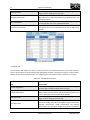
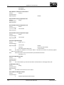
Spindle Specifications
Microlution, Inc. offers different spindle options for the 363-S. The specifications for the most common spindles
offered are listed in Tables 3.4 through 3.8. Please see the “Hardware Introduction” section for more information
on the different applications of each spindle.
Table 3.4: 50 000 RPM Electric Motor Driven High-Precision Bearing Spindle (NR40-5100 ATC) Specifications
Maximum Speed
50 000 RPM
Air for Collet Opening
0.55 MPa – 0.61 MPa [80 PSI - 87 PSI]
Spindle Accuracy
< 2 microns [0.00008”]
Weight
0.74kg [1 .63 lbs]
Power Consumption Rating
18 A (30)
Maximum Output Power
350 W
Table 3.5: 40 000 RPM Electric Motor Driven High-Precision Bearing Spindle (NR-5041E ATC) Specifications
Maximum Speed
40 000 RPM
Air for Collet Opening
0.50 MPa - 0.56 MPa [73 PSI - 87 PSI]
Spindle Accuracy
< 2 microns [0.00008”]
Standard Size Collet Chuck
3.175 mm [1/8"] diameter
Weight
1.34 kg [2.95 lbs]
Power Consumption Rating
18 A (30)
Maximum Power
350 W
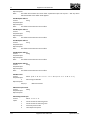
Table 3.6: 50 000 RPM Electric Motor Driven High-Precision Bearing Spindle (IBAG-HF45A60CP) Specifications
Maximum Speed
50 000 RPM (60 000 RPM with liquid chilled spindle
block)
Air for Collet Opening
0.55 MPa - 0.7 MPa [80 PSI - 101 PSI]
Pressure Air Seal
0.2 MPa
Spindle Accuracy
< 2 microns [0.00008”]
Standard Size Collet Chuck
3.175 mm [1/8"] diameter
Weight
2.3 kg [5.1 lbs]
Continuous Power
500 W
Maximum Power
975 W
Table 3.7: 100 000 RPM Ceramic Hybrid Ball Bearing Spindle (Jaeger: Z33-D11100.02S2Y) Specifications
11
Machine Information
September 2011
III
Machine Information
Maximum Speed
100 000 RPM
Air for Collet Opening
0.55 MPa - 0.7 MPa [80 PSI - 101 PSI]
Standard Size Collet Chuck
3.175 mm [1/8"] diameter
Weight
1.1 kg [2.4 lbs]
Continuous Power
360 W
Maximum Power
410 W
Table 3.8: 80 000 RPM Electric Motor Driven Air Bearing Spindle (NRA-5080) Specifications
Maximum Speed
80 000 RPM
Air Consumption for Air Bearing
100 liters/min @ 0.49 MPa [3.53 CFM @ 71 PSI]
Spindle Accuracy
< 1 micron [0.00004”]
Standard Size Collet Chuck
3.175 mm [1/8"] diameter
Weight
0.96 kg [2.1 lbs]
Maximum Power
300 W
Table 3.9: 160 000 RPM Air Turbine-Air Bearing Spindle (ABS-1600) Specifications
12
Maximum Speed
160 000 RPM
Proper Air Pressure for Air Turbine
0.29 MPa – 0.49 MPa [42 psi-71 psi]
Air Consumption for Air Turbine
100 liters/min @ 0.49 MPa [3.53 CFM @ 71 PSI]
Proper Air Pressure for Air Bearing
0.49MPa [71 PSI]
Air Consumption for Air Bearing
40 liters/min @ 0.49MPa [1.41 CFM @ 71 PSI]
Spindle Accuracy
< 1 micron [0.00004”]
Radial Bearing Load Capacity
< 6 N @ 0.49 MPa [1.35 lbf @ 71 PSI]
Thrust Bearing Load Capacity
< 6 N @ 0.49 MPa [1.35 lbf @ 71 PSI]
Standard Size Collet Chuck
3.175 mm [1/8"] diameter
Weight
0.91 kg [2 lbs]
Maximum Power
14 W
Machine Information
September 2011
IV
Software Introduction
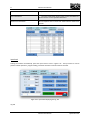
SOFTWARE INTRODUCTION
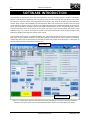
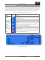
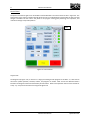
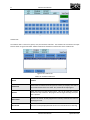
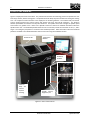
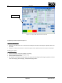
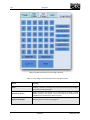
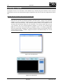
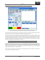
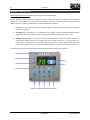
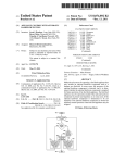
Upon opening the Microlution 363-S CNC Control Software, the main interface window is visible as indicated in
Figure 4.1. This window is divided into four main panels and a menu bar across the top. Each button on the menu
bar will open a separate window containing additional functionality. The panels in the main interface window are
used for direct control of and feedback from the Microlution 363-S CNC machine tool. Located within each panel
are several tabs as shown in Figure 4.1. A tab can be toggled by pressing the corresponding button at the top of its
panel. The functionality of each tab as well as each panel is described in this section. Also described in this section
is the functionality of each control button located within the various tabs of the Microlution 363-S CNC Control
Software. A step – by – step set of instructions on how to operate the 363-S machine tool through the CNC Control
Software is detailed in the Operation section of this manual.
The remainder of this section is organized as follows. First, instructions for how to use the on-screen keyboard are
given. Next, the menu buttons and their corresponding windows are detailed. Next, the four panels are presented,
and the tabs within each of these panels are described in detail. Also included in this discussion is a description of
the functionality of each of the buttons within the tabs.
Menu Buttons
On-Screen Keyboard
Figure 4.1: Program Start-up Screen with CNC Control Panel, Dashboard, View Panel, Input Panel and Menu
Buttons in the top row. Also, the on-screen keyboard button is shown in the lower-right of the screen.
13
Software Introduction
September 2011
IV
Software Introduction
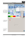
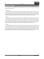
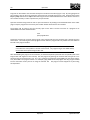
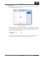
Touchscreen Alignment Procedure
1. Click/touch the Elo
icon in the system
tray on the bottomright side of the
screen. In the pop-up
menu, select Align…
2. Touch the center of
the targets that pop
up on the screen.
3. Repeat steps 1 and
2 until you are
satisfied with the
alignment.
14
Software Introduction
September 2011
IV
Software Introduction
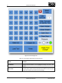
On-Screen Keyboard
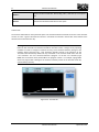
A third-party software package is used as an on-screen keyboard to input characters and commands into the
machine tool’s computer. The keyboard is initiated upon startup of the machine. Figure 4.2 shows the layout of the
on-screen keyboard. Table 4.1 gives a description of the menu buttons on the keyboard. For more information
about the touch-screen keyboard, you can visit the software’s official website at http://www.chessware.ch.
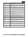
Table 4.1: On-screen keyboard menu button descriptions
Button
Menu
Right-Click
Image
Function
Pulls up the main menu for the keyboard. It is usually a good idea to change
the mode to Floating after startup so that the keyboard can be dragged
anywhere on the screen.
After pressing this button, the next time the screen is touched a right-click
will be simulated. After the right-click occurs this button is no longer
enabled, and any subsequent touch of the screen will result in a normal
left-click.
Switch
Language
Allows the user to switch the keyboard keys to a different character set.
Currently, English is the only language available.
Hide
Hides the keyboard from view. The keyboard can be unhidden by pressing
the button in the lower right of the screen that shows up while the
keyboard is hidden.
Power
Turns off the keyboard. The easiest way to reopen the keyboard after
turning it off is through the Start menu.
Figure 4.2: On-screen keyboard
15
Software Introduction
September 2011
IV
Software Introduction
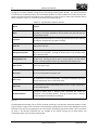
Menu Buttons
Additional panel tabs are located at the top of the main Start-up screen as labeled in Figure 4.1. Clicking on the
icon brings up the panel.
Setup
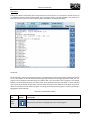
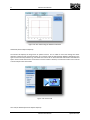
The Setup menu button is located in the upper left corner of the main interface window at startup. The Setup
Window (Figure 4.3) is used for initial motor homing, motion setup, and may contain customized setup software
(see Appendix A for customized setup instructions). Upon machine power-up, the motors must be phased. See the
Software Startup and Homing the Motors sub-section under the Operation section of this manual for instructions
on this procedure.
Figure 4.3: Setup Window
New Program
16
Software Introduction
September 2011
IV
Software Introduction
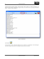
Clicking the New menu button will open a simple text editor, shown in Figure 4.4, to write short programs. The
editor also has the ability to download the program directly to the 363-S memory by pressing the Download
button. The editor is shown in Figure 4.4.
Figure 4.4: PMAC Editor
Open Program
The Open button will open a dialog box allowing the user to browse for a preexisting file. After selecting the
desired file clicking the Open button in the dialog box will load the file into the editor.
17
Software Introduction
September 2011
IV
Software Introduction
Login
The Login menu button will open a window where a user login name and password can be entered (shown in
Figure 4.5). The default user is loaded upon startup and this button must then be used in order to change users.
Figure 4.5: User login window
Administration
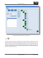
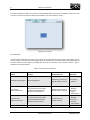
The Admin menu button will open a new window for user account setup (shown in Figure 4.6). By double clicking
on a user account in the user account list box, the controls that user has access to can be modified. On the right
side of the window is a list of all available controls. These controls can be toggled on/off for each user. The controls
that are deactivated can be either shown as disabled or hidden depending on the radiobutton that is toggled. Also,
the user login name and password can be changed in their corresponding text boxes. After any modifications have
been made to a user account, the Save button must be pressed to implement and save those changes. The
controls for additional add-on features that have not been purchased will be disabled. The Default and Admin
users are permenant and cannot be deleted.
18
Software Introduction
September 2011
IV
Software Introduction
Figure 4.6: Administration window for user account setup
Update
The Update menu button will open a new window, shown in Figure 4.7 where a 25 digit access code can be
entered to enable any 363-S mMT add-on features. Popular add-on features include a laser distance sensor, a tool
changer, a camera vision system, and several different spindle options to name a few. Upon purchasing one of
these add-on features, an access code will be supplied by Microlution, which can be entered in this window to
unlock the corresponding software controls. Confirmation that the upgrade was successful will be given upon
entering a correct access code. In order to use the newly available software controls, they must be activated in the
user account setup window for each user.
19
Software Introduction
September 2011
IV
Software Introduction
Figure 4.7: Upgrade window
20
Software Introduction
September 2011
IV
Software Introduction
Panels
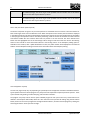
There are four panels in the main interface window of the Microlution 363-S CNC Control Software as shown in
Figure 4.1. The panels are the Dashboard, Control Panel, View Panel, and Input Panel. Each panel, except the
Dashboard, has several tabs where similarly grouped controls are contained. Each tab can be accessed by pressing
its corresponding botton at the top of its panel. The remainder of this section describes in detail the tabs in each
panel and the controls contained in each tab.
Dashboard
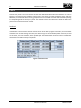
Start-up opens the Dashboard in the upper left corner as shown in Figure 4.8. This panel shows the current state
of the machine. The top sections shows the current location of the axes in program coordinates, the current offset
of the axes from its initial homing coordinates, the distance-to-go to the commanded position each axis, the load
on each motor, the vector feedrate, and the spindle speed. The bottom section shows the active G-codes and Mcodes and the tool that’s currently in the spindle.
Figure 4.8: Dashboard
21
Software Introduction
September 2011
IV
Software Introduction
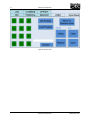
Control Panel
The panel in the bottom right corner of the Main Interface Window is the Control Panel as seen in Figure 4.9. The
Control Panel is the primary interface through which the user runs CNC programs and operates the laser and tool
changer if available. The four tabs in this panel are for program running, part patterning, laser operation, and
manual tool changer setup and operation.
Tabs
Figure 4.9: Control Panel
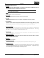
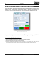
Program Tab
The Program Tab, Figure 4.10, is used to run a single pre-existing G-code program on the 363-S. It is also used to
control the spindle operation, feedrate, coolant, and program run modes. Table 4.2 lists the different buttons
located in the Program Tab and the functionality of each button. Refer to the Operation section of this manual for
a step – by – step set of instructions for using the Program Tab.
22
Software Introduction
September 2011
IV
Software Introduction
Figure 4.10: Program Tab
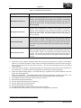
Table 4.2: Program Tab buttons and their functions
Button
Function
Cycle Start
Executes the program from the first line. If the program has been paused it will resume
from the paused line.
Pause
Pauses the program following the execution of the line during which the Pause button was
pressed. Pressing Cycle Start will resume the program from the paused location.
Stop
Halts execution of the G-code and motion of the machine even if it is in the middle of a
move. Pressing Cycle Start after pressing the Stop button will resume the current move
and then execute the next line.
Flood Coolant
Starts or stops flood coolant flow. Air coolant must be turned off to turn on flood coolant.
Air Coolant
Starts or stops air coolant flow. Flood coolant must be turned off to turn on air coolant.
Single Block
This changes the function of Cycle Start. If Single Block is ‘on’ each time Cycle Start is
pressed the machine will only execute the next program line. If Single Block is ‘off’ the
program will continue executing until stopped or completed.
23
Software Introduction
September 2011
IV
Software Introduction
Optional Stop
When optional stop is ‘on’, program execution will pause when an M01 command is given
in the CNC program. If optional stop is turned off, all M01 commands will be ignored
during program execution.
Feedrate
The text box will display the feedrate from the G-code. The Override box is used to scale
the G-code feedrate commands.
Override
Override will increase or decrease the displayed feedrate by the percentage displayed in
the Override text box. This can be useful to slow down a program and monitor all
operations to ensure they are completed as anticipated or speed up the program to
determine optimum feedrates. The maximum override is 200% of the displayed feedrate.
Note: Changing the Override will not change the feedrate displayed in the
Feedrate Text Box. However, the displayed feedrate is scaled by the
percent listed in the Override Text Box. The true feedrate is the scaled
override value of the displayed feedrate in the Feedrate Text Box.
Enable Spindle
Turns the air supply to the air bearings in the spindle on. When the spindle is enabled the
speed can be set and the spindle started and stopped, the tool release is also disabled so
that a tool cannot be released while in motion.
RPM
The RPM Text Box displays the desired spindle speed. The spindle must be enabled to
modify the RPM text box. Click the Set button to set the spindle speed to the displayed
value. The spindle must be enabled and on to adjust spindle speed. The +/- buttons will
increase or decrease the spindle speed by the displayed increment.
Laser Inspection Tab (LT-9000 Confocal Laser Option Required)
The Laser Inspection Tab (see Figure 4.12) allows the user to scan a part using a built-in scan path or by using a
user-defined scan path. Table 4.4 lists the applicable buttons and their functions for the Laser Inspection Tab.
Refer to the Operation section of this manual for a step – by – step set of instructions for using the Laser
Inspection Tab.
24
Software Introduction
September 2011
IV
Software Introduction
Figure 4.12: Laser Inspection Tab
Table 4.4: Laser Inspection Tab buttons and their functions
Button
Function
Predefined Scanning Pattern
Select pattern to use.
Rectangular Area (X Scan)
(Pulldown Menu)
Rectangular Area (Y Scan)
(Pulldown Menu)
Circular Area (R Scan)
(Pulldown Menu)
Circular Area (Arc Scan)
(Pulldown Menu)
25
Sets the scan to proceed from the start X and Y position to the end X
position. After reaching the end X position, the Y position is incremented
towards the Y end position by the step amount and scans from the end X
value to the start X value. This process repeats until the end value of X
and Y is reached.
Sets the scan to proceed from the start X and Y position to the end Y
position. After reaching the end Y position the X position is incremented
towards the X end position by the step amount and scans from the end Y
value to the start Y value. This process repeats until the end value of X
and Y is reached.
The scan will move radially starting at the start radius and start angle until
the end radius is reached. The angle will be incremented by the step
amount and the scan will proceed along the new radius until reaching the
start radius. This process repeats until the end value of radius and angle is
reached.
The scan will move along an arc starting with a radius equal to the start
radius and angle equal to the start angle. The angle will increment until
the end angle is reached. The radius will then be incremented by step
amount. The scan will then decrement the angle until the start angle is
reached. This process repeats until the end value of radius and angle is
Software Introduction
September 2011
IV
Software Introduction
reached.
User Defined Scanning Program
Allows the user to load a G-code program to control the scan, useful for
more complex scans or sequentially completing multiple types of scans.
Sample Spacing in Scanning Dir
(mm)
Distance between samples. Data points will be collected every time the
distance traveled increases by this number.
Sampling Rate (Hz)
Sampling rate desired on laser system. This is used in conjunction with
sample spacing to determine feed rates. Fast sampling rates, however, can
cause data points to be missed. 1 kHz is recommended sampling speed,
but up to 2 kHz is typically reliable.
Setup
Loads the program and verifies that a valid filename and directory have
been entered.
Start
Begins scanning.
Stop
Ends scanning and saves data, if only a few degrees of a circular area (R
Scan) are desired the program can be stopped after the desired data has
been collected.
Data File Setting
Choose directory and filename for data to be saved.
Enable Laser
Must be enabled for data to be collected.
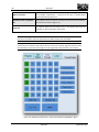
Tool Changer Tab (Automatic Tool Changer Option Required)
The Tool Changer Tab, Figure 4.13, is functional on machines that feature the automatic tool changer system. This
tab allows users to interact with the tool changer. There are 36 tool locations in the tool carousel. Table 4.5 lists
the applicable buttons and their functions.
Note: The Tool Changer system will home at power up and remain at position “zero” until tool
loading begins. It is recommended that all tools are loaded into the wheel and removed from the
spindle at power up to ensure proper operation.
26
Software Introduction
September 2011
IV
Software Introduction
Figure 4.13: Tool Changer Tab
Table 4.5: Tool Changer Tab buttons and their functions
Button
Tool Buttons
Select Tools
27
Function
Shows the user which tools have been selected and are available for tool
change. The tool buttons can be highlighted through the Select Tools
button.
Enables all tool buttons to allow the user to highlight tools that are
currently in the system. Pressing the Select Tools button a second time will
disable all tool buttons and save the current setting.
Software Introduction
September 2011
IV
Software Introduction
Index Carousel
Indexes the tool carousel to the tool number listed in the textbox to the
right of the button.
Index Carousel to Spindle Tool
Indexes the tool carousel to the tool number that is currently in the
spindle, if the spindle tool is known. The spindle tool is established after
the first tool change after power up.
Open Gripper
Opens the tool changer gripper to allow user to remove tool if necessary.
Close Gripper
Closes the tool changer gripper to allow user to replace tool if necessary.
Open Door
Opens tool changer door.
Close Door
Closes tool changer door.
Pressure On/Off Switch
Turns the air pressure for the pneumatic tool changer on or off. The air
pressure should be on for all tool changes.
Select All
Highlights all tool buttons, indicating that all tools are in the system.
Unselect All
Removes the highlight from all tool buttons, indicating that no tools are in
the system.
Load Tool
Performs a tool change. After pressing the Load Tool button, choose a
highlighted tool button to change to that tool.
“X” Button
Cancels a tool change started with the Load Tool button but before the
tool is selected.
Home
Resets the tool carousel to ensure that it is in the correct position.
Pause Tool Changer
Pauses the tool change. Can be resumed by pressing the button a second
time.
28
Software Introduction
September 2011
IV
Software Introduction
View Panel
Starting the software automatically opens the View Panel as seen in Figure 4.14. View Panel is used for the user to
see feedback information from the 363-S mMT and its peripheral devices. The tabs included in this panel are GCode, Axis, Camera, Laser, Error Status, Warning Status, Tool Offsets, and Workpiece Offsets.
Figure 4.14: View Panel, GCode Tab
G-Code Tab
The G-Code Tab in the View Panel (shown in Figure 4.14) displays the current program that is loaded and ready to
be run. The program can be searched/scrolled through using the buttons to the right described in Table 4.6. The
program can be loaded and unloaded using the Combine Tab in the Input Panel. Once a program is successfully
loaded, it can be executed with the Cycle Start button in the Program Tab of the Input Panel. It can be executed
from any line in the G-Code window. Note, take care when starting from the middle of the program to ensure all
offset, etc are setup correctly. While a program is running, the line of code the program is currently executing is
highlighted in the G-Code Tab.
Table 4.6: G-Code Window Buttons
Item
Begin
Button
29
Button
Functionality
Moves the G-Code cursor to the beginning of the G-Code program.
Software Introduction
September 2011
IV
Software Introduction
Page Up
Button
Moves the G-Code cursor up one page of the G-Code program.
Line Up
Button
Moves the G-Code cursor up one line of the G-Code program.
Edit Button
Enables the user to edit the currently selected line of G-Code text.
Find Button
Opens a find/replace window allowing the user to quickly search for/replace text. Note,
use caution when using the replace all functionality. Replacing many lines in a large file
can be very slow.
Line Down
Button
Moves the G-Code cursor down one line of the G-Code program.
Page Down
Button
Moves the G-Code cursor down one page of the G-Code program.
End Button
Moves the G-Code cursor to the end of the G-Code program.
Axis Tab
The Axis Tab in the View Panel opens the Machine Tool Status Graph shown in Figure 4.15. This is a graphical
representation of the current position of the cutting tool. The blue lines indicate the program coordinate system.
The graph has units of mm and (0,0) refers to the machine origin. The red lines indicate the axes maximums and
thus define the working volume of the machine. The user can click, hold, and drag a box on either graph to zoom
in. Zooming out is achieved by right clicking and selecting Un-Zoom or Undo All Zoom/Pan. Right clicking the
graphs with the mouse displays such options as copy, save, and print. This feature is useful for monitoring the
utilization of the working volume. During setup, this feature can be used to adjust the fixturing of the workpiece
so that it falls within the working volume. To verify the workpiece is within the working volume, move the stages
[ensure stages are killed (refer to Table 4.5 for more information on killing stages)] around the edges of the
workpiece and watch the Machine Tool Status to confirm the workpiece falls within the working volume. The Clear
Part Pattern Array button will clear any part pattern array that is displayed on the Machine Tool Status Graph.
30
Software Introduction
September 2011
IV
Software Introduction
Figure 4.15: Axis Tab showing the Machine Tool Status
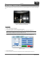
CameraTab (Camera Option Required)
The Camera Tab displays the image from an optional camera. This is useful for visual tool settings and other
operation monitoring and real time inspection. The contents of this tab will be slightly different depending on the
type of camera that is purchased. Fig. 4.16 shows the controls for an EO-3112C Color USB Camera from Edmund
Optics. These controls shown here are the same as for the camera’s software, so consult the camera’s user manual
or online help for more information.
Figure 4.16: Camera Tab
Laser Tab (LT-9010 Confocal Laser Option Required)
31
Software Introduction
September 2011
IV
Software Introduction
The Laser Tab (shown in Figure 4.17) shows the camera feedback from the Keyence LT-9010M or similar laser with
a camera in the laser head. This tab will only be available if your laser includes a camera.
Figure 4.17: Laser tab
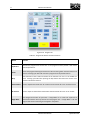
Error Status Tab
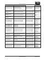
The Error Status Tab displays the status of error alarms on the 363-S (shown if Figure 4.18). If the indicator next to
an alarm is green, then that alarm functioning properly. If the indicator is red, then a fault has been registered and
the alarm must be cleared before proceeding with many of the functions on the machine. Table 4.7 gives a
description of each of the alarms.
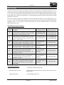
Table 4.7: Error Alarms on the 363-S
Alarm
Cause(s)
System Response
Recovery
Procedure
Workpiece Probing Error
See Probing Manual
Machining cycle will stop
Spindle rotation will stop
See Probing
Manual
Tool Length
Measurement Error
Tool measurements not within
specified repeatability band
Tool sensor beam blocked
Machining cycle will stop
Spindle rotation will stop
Tool Diameter
Measurement Error
Tool measurements not within
specified repeatability band
Tool sensor beam blocked
Program will stop
Spindle will stop
Tool Breakage Alarm
Tool breakage detected
System pause
32
Software Introduction
Check for beam
blockage
Re-run tool
length
measurement
Check for beam
blockage
Re-run tool
diameter
measurement
Replace tool
September 2011
IV
Software Introduction
Tool Dirty Alarm
Dirty tool detected
System pause
Clean tool
E-Stop Circuit Tripped
E-stop button pressed
Controller watchdog fault
Regen resistor temperature fault
Motors de-energized
Spindle de-energized
Correct cause of
E-stop trigger
X-Axis Travel Limit
Exceeded
Software travel limit exceeded
Machine motion stopped
Y-Axis Travel Limit
Exceeded
Software travel limit exceeded
Machine motion stopped
Z-Axis Travel Limit
Exceeded
Software travel limit exceeded
Machine motion stopped
X-Axis Following Error
Y-Axis Following Error
Z-Axis Following Error
Following error limit exceeded
Following error limit exceeded
Following error limit exceeded
All motors de-energized
All motors de-energized
All motors de-energized
Check for any
restrictions to
motion
Re-initialize
machine
X-Axis Amplifier Fault
Y-Axis Amplifier Fault
Z-Axis Amplifier Fault
Amplifier fault
Amplifier fault
Amplifier fault
All motors de-energized
All motors de-energized
All motors de-energized
Re-initialize
machine
X-Axis Warning Error
Y-Axis Warning Error
Z-Axis Warning Error
Warning error limit exceeded
Warning error limit exceeded
Warning error limit exceeded
All motors de-energized
All motors de-energized
All motors de-energized
Check for any
restrictions to
motion
Re-initialize
machine
Interlock Fault
Attempt to start machining cycle or
spindle with lid open
Machining cycle will stop
Spindle rotation will stop
Close lid
Tool Changer Fault
Multiple Errors, see software
message
Machining cycle will stop
Spindle rotation will stop
Positioning Fault
Machine not in home position during
home check.
Machining cycle will stop
Spindle rotation will stop
Robot Fault
Issue performing an automatic pallet
change.
Machining cycle will stop
Spindle rotation will stop
System Pressure Loss
Loss of system pressure
Machining cycle will stop
Machine will move to safe
position
33
Software Introduction
Check for
programming
errors
Jog axes to
within travel
limits
Follow software
message
instructions
Move machine to
Home and restart
program.
Check for robot
issues and restart
program.
Restore system
pressure
Reinitialize
machine
September 2011
IV
Software Introduction
Figure 4.18: Error Status Tab
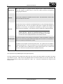
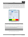
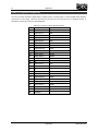
Warning Status Tab
The Warning Status Tab displays the status of warning alarms on the 363-S (shown if Figure 4.19). If the indicator
next to an alarm is green, then that alarm functioning properly. If the indicator is red, then a fault has been
registered and the alarm must be cleared before proceeding with many of the functions on the machine. Table 4.8
gives a description of each of the alarms.
Table 4.8: Warning Alarms on the 363-S
Alarm
Cause(s)
System Response
Spindle Motor
Disconnected
Spindle motor disconnected
Spindle will not start
Spindle Warning
High spindle motor cooling air
pressure fault
Spindle torque overload warning
Spindle motor current overload
warning
Spindle over-speed warning
34
Software Introduction
No action
Recovery
Procedure
Check for loose /
disconnected
connections
Check Warning
Code on
Spindle
Controller
Correct cause of
warning code
September 2011
IV
Software Introduction
Spindle Error
Spindle torque overload fault
Spindle motor current overload fault
Low spindle motor cooling air
pressure fault
Spindle over-speed fault
Power cycled on controller box with
spindle commanded to be spinning
Spindle will stop
Program will stop
Spindle will not start
Check Error Code
on Spindle
Controller
Correct cause of
error code
X-Axis Velocity Error
Y-Axis Velocity Error
Z-Axis Velocity Error
Velocity limit exceeded
Velocity limit exceeded
Velocity limit exceeded
Machining cycle will stop
Spindle rotation will stop
Re-initialize
machine
Figure 4.19: Warning Status Tab
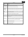
Workpiece Offsets Tab
The Workpiece Offsets Tab displays the values of all the workpiece offsets on the 363-S (shown if Figure 4.20). All
offsets can be accessed through paging back and forth or through searching for an offset number. Offsets can be
saved and recalled for later use. Table 4.9 gives a description of each of the items on the panel.
Table 4.9: Workpiece Offsets on the 363-S
Item
Previous Page Button
Index to Offset Button
35
Functionality
The previous page button allows users to flip back through the
previous pages of offsets stopping at the first page.
The index to offset button enables the user to type in an offset
number, press the button and be automatically taken to the
correct offset page with the desired offset selected.
Software Introduction
September 2011
IV
Next Page Button
Workpiece Offset Table
Save to File Button
Retrieve from File Button
Software Introduction
The next page button allows users to flip through the next
pages of offsets stopping at the last page.
The workpiece offset table holds the offsets for G-Codes G54 –
G59 and G54.1 P1 – 394. These offsets can be updated by the user
through this table.
The save to file button writes all the current workpiece offsets
to a file and saves it to a user specified destination.
The receive from file button takes a user specified offset file
and replaces all the current workpiece offset with the offsets from
that file.
Figure 4.20: Workpiece Offsets Tab
Tool Offsets Tab
The Tool Offsets Tab displays the values of all the tool offsets and compensation factors on the 363-S (shown if
Figure 4.21). All offsets can be accessed through paging back and forth or through searching for an offset number.
Offsets can be saved and recalled for later use. Table 4.10 gives a description of each of the items on the panel.
Table 4.10: Tool Offsets on the 363-S
Item
Previous Page Button
Index to Offset Button
Next Page Button
Tool Offset Table
36
Functionality
The previous page button allows users to flip back through the
previous pages of offsets stopping at the first page.
The index to offset button enables the user to type in a tool
offset number, press the button and be automatically taken to the
correct offset page with the desired offset selected.
The next page button allows users to flip through the next
pages of offsets stopping at the last page.
The tool offset table holds the important information about
each tool including tool position, description, length measurement,
diameter measurement, length compensation and diameter
compensation. The description, length compensation and diameter
Software Introduction
September 2011
IV
Software Introduction
compensation can be updated by the user.
Save to File Button
Retrieve from File Button
The save to file button writes all the current tool offsets to a
file and saves it to a user specified destination.
The receive from file button takes a user specified tool offset
file and replaces all the current tool offsets with the offsets from
that file.
Figure 4.21: Tool Offsets Tab
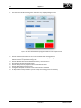
Input Panel
Starting the software automatically opens the Input Panel as seen in Figure 4.22. The Input Panel is used to
perform manual operations, program loading, and direct interaction with the machine controller.
Figure 4.22: Input Panel displaying the Jog Tab
Jog Tab
37
Software Introduction
September 2011
IV
Software Introduction
The Jog Tab is used for manually moving the axes and loading / releasing tools manually. The axes can be moved
incrementally or to absolute positions, and the handheld pendant can also be enabled to manually move the axes.
Figure 4.22 shows the Jog Tab and Table 4.11 lists the buttons and their functions. Refer to the Operation section
of this manual for a step – by – step set of instructions for using the Jog Tab.
Table 4.11: Jog Tab buttons and their functions
Button
Function
Move
Use the Move button to move the stages to absolute or relative coordinates
according to the values specified by the text boxes. Only the axes that are
checked will be moved.
Jog Speed
The jog speed text box displays the current jog speed for all three axes. Moving
the slider bar will adjust the jog speed accordingly.
Check All
Apply action to all axes.
Clamp/Unclamp Pallet
Releases and clamps the pallet. Pressing this button when it displays Clamp
Pallet will clamp the pallet. Pressing the button when it says Unclamp Pallet
will unclamp the pallet.
Clamp/Release Tool
Releases and clamps the automatic tool chuck (automatic tool changing
spindles only). Pressing this button when it displays Release Tool will release
the tool. Pressing the button when it says Clamp Tool will clamp the tool.
Move to Zero
Moves to program origin.
Set to Zero
Sets current axis position to program zero.
Close Loop
Set selected axes to closed loop (enable). The motors will keep the axis in the
commanded position when in closed loop mode.
Open Loop
Set selected axes to open loop (disable). When an axis is in open loop mode it
can be moved manually.
Enable Handwheel
Pressing the button when it displays Enable Handwheel will enable the
handwheel on the handheld pendant. Pressing the button when it displays
Disable Handwheel will disable the handwheel.
MDI Tab
The MDI (Manual Data Input) Tab is used for manually executing G- and M-code commands outside of a CNCprogram (shown in figure 4.23). Commands can be executed by typing them into the text box. Multiple lines can be
executed at the same time by typing them all in the text box and pressing the Execute button. There are buttons
for most G- and M-code commands that are available on the 363-S. Pressing one of these buttons will
automatically insert the command into the text box.
38
Software Introduction
September 2011
IV
Software Introduction
Figure 4.23: MDI Tab
Combine Tab
The Combine Tab is used to find, queue, load, and rewind G-Code files. The Combine Tab is located in the Input
Panel as shown in Figure 4.24 below. Table 4.12 below lists the buttons and functions of the Combine Tab.
Figure 4.24: Combine Tab
Table 4.12: Combine Tab buttons
Button
Function
Load Gcode
Loads all the G-Code files from the queue to memory and displays the code in
the G-Code text box of the View Panel. Also, downloads all subprograms.
Rewind
Makes the first line of the program active. This can be used after a pause
command or stop command. The program will not begin executing until Cycle
Start is pressed.
Close Gcode
Removes the current G-code program from memory and clears the text box
displaying the code.
Save Gcode
Takes the currently displayed Gcode and save it to a file of the user’s choosing.
39
Software Introduction
September 2011
IV
Software Introduction
Browse…
Browse and find G-Code files. After finding a file, it will show up in the queue
box.
Remove
Removes the selected G-Code file from the queue.
Terminal Tab
The Terminal Tab located on the Input Panel opens a Terminal which allows commands to be sent to the controller
one line at a time. Figure 4.25 shows the Terminal. Commands are entered in the text box at the bottom of the
window and sent with the enter key.
Warning: The Terminal Panel has the ability to directly address variables and functions in the
Delta-Tau CNC controller and therefore should be used with caution. Changes to key operating
variables can result in changes in machine accuracy, erratic machine behavior, damage to the
machine and/or personal injury. Only personnel specially trained in the operation of the
Terminal Panel functionality should use any commands in the Terminal Panel other than the
“run” command. The “run” command executes a program. To use the “run” command, type
b###r into the Terminal Panel, where ### is the program number. For example, typing b300r
would run program 300. Damage to the machine caused by misuse of the Terminal Panel may
void the factory warranty.
Terminal Entry Line
Figure 4.25: Terminal Tab
40
Software Introduction
September 2011
IV
Software Introduction
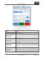
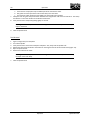
Offset Tab
The Offset Tab (see Figure 4.26) is used to set, save, and load program origins (workpiece offsets). Table 4.13
describes the buttons located within the Offset Tab and their functions. Refer to the Operation section of this
manual for a step – by – step set of instructions for using the Offset Tab.
Figure 4.26: Offset Tab
Table 4.13: Offset Tab buttons and their functions
Button
Function
Apply Saved
Applies a previously saved program origin as the current program origin.
Save Active Origin
First, select the desired offset (G54 through G59) from the drop down box. Next, the Save
Active Origin button will save the active origin as the selected offset.
Save To File
The Save to File button will save all of the offsets (G54 through G59) to a user selected file.
This allows multiple origin offsets to be saved for later use.
Retrieve From File
Retrieves a set of saved program offsets (G54 through G59) from the saved file.
Set New Program
Updates the active program origin with the values next to the selected X, Y, or Z buttons.
X
If enabled (Orange), the active origin will be updated with the number next to this button
when the Set New Program button is pressed.
41
Software Introduction
September 2011
IV
Software Introduction
Y
If enabled (Orange), the active origin will be updated with the number next to this button
when the Set New Program button is pressed.
Z
If enabled (Orange), the active origin will be updated with the number next to this button
when the Set New Program button is pressed.
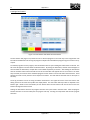
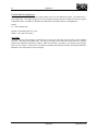
Sensor Tab (Tool Sensor option required)
The Sensor Tab (shown in Figure 4.27) is used to perform an automated tool sense routine. There are buttons for
both a tool length sense and a tool diameter sense. When the operations are finished, the result data is displayed
in the adjacent text box. This data is automatically saved into the registers for the tool number listed in the textbox
in the top-right. No experience value is used when performing a tool sense with this method. The Select Carousel
Tools button enables the user to detect which tools are present in the tool carousel. The Sense Selected Tools
button uses the highlighted tools in the Tool Changer Tab to change to and sense each tool. See the Tool Sensing
section of this manual for more information about the tool sensing routine. If the workpiece probing option is
available on the machine, after a pallet identification routine, the pallet number will be displayed in the Pallet ID
textbox. See the Workpiece Probing manual for more information about the workpiece probing.
Figure 4.27: Sensor Tab
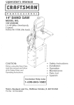
User Tab (Options required)
The User Tab, Figure 4.28, may vary depending on special options and equipment included on individual machines.
Typical options found here will be program array setup and manual operation of special pneumatic systems. These
system include tool guarding, mandrel clamping, and robot door actuation.
The program array setup can be used to repeat a loaded program at each spot on the array. These locations are
defined in the workpiece offset table, offsets #1 - #12. Select the correct pockets for milling using the Set Pockets
button, browse to the correct program file through the Browse button, and then load the program by clicking the
Load Program button. Press Cycle Start to begin.
42
Software Introduction
September 2011
IV
Software Introduction
Figure 4.28: User Tab
43
Software Introduction
September 2011
V
Hardware Introduction
HARDWARE INTRODUCTION
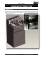
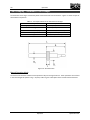
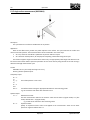
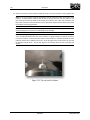
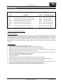
Coordinate Axes
The coordinate system for the 363-S is a right-handed system set up with the positive x-axis extending to the right
(when facing the machine), the positive y-axis extending up, and the positive z-axis extending toward the front of
the machine as seen in Figure 5.1.
Y
X
Z
Figure 5.1: Coordinate axes
44
Hardware Introduction
September 2011
V
Hardware Introduction
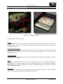
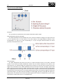
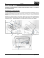
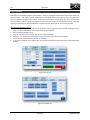
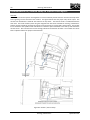
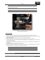
Pallet and Spindle Mounting
Spindle Mount
X-Y Stage
Protective
Rigid Seals
Erowa Pallet Mount
Z Stage
Z Stage
Figure 5.2: X-Y-Z stage introduction
The following items reference Figure 5.2.
X-Y Stage
The X-Y stage moves in the X-Y plane and has 2.48” (63 mm) of travel in each direction. Pallets (see “Work Piece
Mounting System” Section for an introduction to pallets) are mounted to the Erowa pallet mounting system
located on the X-Y stage.
Erowa Pallet Mounting System
The Erowa pallet mount system allows pallets to quickly and easily be changed with sub-micron repositioning
repeatability. The mounting system uses a pneumatic chuck to position the pallet. This connection assures
repeatable positioning.
Protective Rigid Seals
The protective rigid seals keep chips and fluid out of the machine motion and electronic components while still
allowing motion of the stages.
Z Stage
The Z stage moves in the Z direction and has a total travel range of 3.94” (100 mm). Available machining travel
range depends on the spindle, workpiece fixture, and installed options (such as an automated tool changer).
Spindles (detailed in the Spindle Introduction) and optional metrology equipment are mounted to the spindle
mounts located on the Z stage.
Spindle Mount
The spindle mount allows for quick spindle changes with highly repeatable positioning. The spindle mounting
system uses 6 bolts to rigidly hold the spindle block to the z-axis stage.
45
Hardware Introduction
September 2011
V
Hardware Introduction
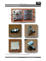
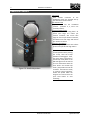
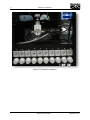
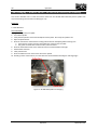
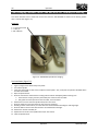
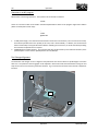
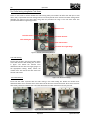
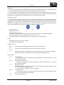
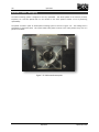
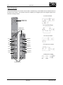
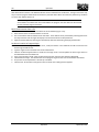
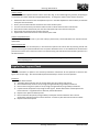
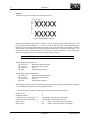
Work Piece Mounting System
8
6
7
9
1. Pallet Back and Front
2. Spigot
3. Pallet with Spigot Attached
4. Machinable Fixture Plate
5. Complete Pallet System
The following items reference Figure 5.3.Figure 5.3: Pallet System Introduction
46
Hardware Introduction
September 2011
V
Hardware Introduction
1. Pallet
The front face of the pallet is smooth with four threaded (7) and four unthreaded (8) mounting holes around the
edges of the pallet. The mounting holes enable the machinable fixture to be securely fastened to the pallet. The
notch (9) seen at the bottom of the pallet indicates the correct mounting orientation. The notch should face
towards the floor when mounted to the machine. The backside of the pallet has the Erowa pallet mounting
system. This system permits easy and repeatable mounting of the pallet/workpiece to the X-Y stage.
6. Erowa Pallet Mounting System
The Erowa pallet mounting plate ensures accurate and repeatable pallet placement on the X-Y stage.
7. Threaded Mounting Holes
These four holes allow the interface plate and/or the machinable fixture to be securely mounted to the pallet.
8. Non-Threaded Mounting Holes
The non-threaded mounting holes allow for quick and secure mounting of the machinable fixture plate to the
pallet.
9. Notch
There is a notch in the pallet and machinable fixture plate to indicate the correct mounting orientation (notches
should be aligned). When mounted on the machine, the notch should face towards the floor.
2. Spigot
The spigot rigidly holds the pallet to the X-Y stage. The Erowa plate on the back of the pallet ensures that the
spigot positioning is very accurate.
3. Pallet with Spigot Attached
This shows the correct orientation of the spigot and the pallet.
4. Machinable Fixture Plate
The aluminum machinable fixture plate offers a smooth surface upon which to mount the workpiece. The plate
also functions as a sacrificial surface for machining a through feature.
5. Complete Pallet System
Picture five shows the correct completed pallet system.
47
Hardware Introduction
September 2011
V
Hardware Introduction
Spindle Introduction
There are several different spindle options available for the Microlution 363-S. These options include: 160 000
RPM air turbine-air bearing spindle (ABS-1600), 80 000 RPM electric motor driven spindles (NRA-5080), and 40 000
(NR-5041E ATC) and 50 000 (NR40-5100 ATC) RPM electric motor driven spindles with automatic tool changing
functionality.
40 000 (NR-5041E ATC) & 50 000 (NR40-5100 ATC) RPM Electric Motor Driven Spindles with Automatic
Tool Changing Capability (pictured in Figure 5.4)
Ideal for larger Diameter tools up to 0.125” (3.175 mm)
These spindles are driven by an electric brushless motor. The brushless motor provides a long service life,
excellent durability, and high reliability. Both the 40 000 and 50 000 RPM spindles utilize an air operated collet to
easily change tools. Both spindles use high precision bearings to obtain spindle accuracy within 2 microns.
50 000 (IBAG - HF45A60CP) RPM Electric Motor Driven Spindles with Automatic Tool Changing Capability
Ideal for larger Diameter tools up to 0.276” (7.0 mm)
These spindles are driven by an electric brushless motor. The brushless motor provides a long service life,
excellent durability, and high reliability. This spindle utilizes an air operated collet to easily change tools and high
precision bearings to obtain spindle accuracy within 2 microns. The spindle can be operated at a maximum RPM of
60,000 if a liquid chilled spindle block is used to house the spindle. Please contact Microlution for more details.
100 000 (Jaeger: Z33-D11100.02S2Y) RPM Ceramic Hybrid Ball Bearing Spindle with Automatic Tool
Changing Capability
Ideal for larger Diameter tools up to 0.125” (3.175 mm)
These spindles are driven by an electric brushless motor. The motor/spindle combination is connected to a spindle
control unit which controls the spindle speed. The brushless motor provides a long service life, excellent
durability, and high reliability. This spindle utilizes an air operated collet to easily change tools and high precision
bearings to obtain spindle accuracy within 2 microns. Please contact Microlution for more details.
80 000 RPM Electric Motor Driven Spindles (NRA-5080)
Ideal for use with tools up to: 0.050” (1.27 mm) in diameter for the air bearing option and 0.125” (3.175 mm) in
diameter for the ceramic bearing option
These spindles use an electric brushless motor to drive different spindles. The brushless motor provides a long
service life, excellent durability, and high reliability. The motor/spindle combination is connected to a spindle
control unit which controls the spindle speed. There are two different bearing options for the 80 000 RPM Electric
Motor Driven Spindle. These two bearing options are air bearings and ceramic bearings. The air bearing spindle
produces extremely low heat and vibration and has a very long service life because of low friction and wear. The
air bearing provides exceptional spindle accuracy of within one micron. The ceramic bearing spindle has a spindle
accuracy within one micron and requires an oil mist air flow for lubrication.
160 000 RPM Air Turbine-Air Bearing Spindle (ABS-1600)
48
Hardware Introduction
September 2011
V
Hardware Introduction
Ideal for use with small tools up to 0.02” (0.508 mm) in diameter
Air turbine spindles use an air turbine instead of an electric motor to drive the spindle. The air turbine-air bearing
spindle has a maximum spindle speed of 160 000 rpm which is much higher than electric motor driven spindles.
Additionally the air turbine-air bearing spindle uses an air bearing which produces extremely low heat and
vibration and has a very long service life because of low friction and wear. The air bearing provides a spindle
accuracy within one micron.
Figure 5.4: One spindle option, 50 000 RPM Electric Motor Driven
Automatic Tool Changing Spindle, with mounting system
49
Hardware Introduction
September 2011
V
50
Hardware Introduction
Hardware Introduction
September 2011
V
Hardware Introduction
Front of the Machine
Figure 5.5 displays the front of the 363-S. The protective lid encloses the machining process and protects the user
from chips, coolant, and the moving parts. The protective lid also keeps chips and coolant from exiting the working
area. The computer monitor functions as the display for all machining software. The machine body and control
systems housing protects the control systems and shields users from the internal electronics. The vibration
isolation pads shelter the machine from any floor vibrations. The spindle control unit manages the spindle speed
and monitors any spindle errors. Refer to the Spindle Control Unit section for detailed information about the
spindle control unit. The handheld pendant allows the user to manually control the movement of the X, Y, and Z
stages. The emergency stop button is located on the handheld pendant. More information about the handheld
pendant is available in the Handheld Pendant section and in the Using the Handwheel section.
Protective Lids
Touchscreen
Monitor
Handheld
Pendant
Machine
Body and
Control
Systems
Housing
Spindle Control,
Regulators, PC
Figure 5.5: Front of the machine
51
Hardware Introduction
September 2011
V
Hardware Introduction
Handheld Pendant
1. Handwheel
Each rotation increment of the
handwheel moves the selected axis by
the selected increment amount.
2. Axis Selection Dial
Adjusts which axis the handwheel
controls. (Positions 4, 5, and 6 are
currently inactive).
3. Increment Selection Dial
Adjusts the handwheel scaling factor. X1
moves each stage one micron per
rotation increment, X10 moves each
stage ten microns per rotation increment,
and X100 moves each stage 100 microns
per rotation increment.
4. Emergency Stop Button
The Emergency stop button shuts off the
power to the spindle and stage motors.
Figure 5.6: Handheld pendant
52
Hardware Introduction
Note: To return the machine to
normal operation after pressing
the E-stop, twist the E-Stop
clockwise to disengage it. Next,
the linear motors need to be in
closed loop mode (Refer to the
MDI tab segment of this manual
for more information about the
Close button and closed loop
mode.) The spindle must also be
restarted. The machine is ready
to continue normal operation.
Enable the spindle within the
Program Run tab and click the
Cycle Start button to start
machining.
September 2011
V
Hardware Introduction
Machine Regulators
CB. X-Y stage Counterbalance Pressure Regulator
Suspends the X-Y stage to decrease the workload of the Y-axis linear motors. Pressure will vary based on the
weight on the workpiece. Adjust the pressure until the X-Y stage is suspended and stationary.
1. Regulator 1: Tool Collet Pressure Regulator / Airbearing Spindle (optional)
Regulates the pressure used during tool changes on automatic tool changing spindles. Aux 1 can also be used
to supply air to the air bearing spindle options. Suggested air pressure is approximately 0.6 MPa.
2. Regulator 2: Spindle Cooling Air Pressure Regulator
Regulates the spindle motor cooling air pressure. Suggested air pressure is approximately 0.3 MPa.
3. Regulator 3: Coolant Blast Air Regulator
Regulates coolant air applied directly to the work piece. Suggested air pressure is approximately 0.2 MPa.
4. Regulator 4: Pallet Unclamp Regulator
Regulates air pressure of kinematic pallet unclamp action. Suggested air pressure is approximately 0.55 MPa.
5. Regulator 5: Pallet Air Purge Regulator
Regulates air pressure of pallet cleaning air purge. Suggested air pressure is approximately 0.5 MPa.
6. Regulator 6: Tool Sensor Purge Air (option required)
Regulates air pressure of tool sensor purge. Suggested air pressure is approximately 0.4 MPa.
7. Regulator 7: Tool Changer Air Regulator (option required)
Regulates air to the pneumatic actuators on the tool changer. Suggested air pressure is approximately 0.6 MPa.
8. Regulator 8: Tool Clamp Air Regulator (option required)
Regulates air to provide clamping force to the spindle collet (HF45 spindle option required). Suggested air
pressure is 0.2 MPa.
9. Regulator 9: Configurable Auxiliary Regulator
Contact Microlution.
10. Regulator 10: Configurable Auxiliary Regulator
Contact Microlution.
Note: Regulators may have different functions depending on the options chosen
for the machine. Please contact Microlution for the correct regulator function
map if yours do not match what is shown above.
53
Hardware Introduction
September 2011
V
Hardware Introduction
CB
1
2
3
4
5
6
7
8
9
10
Figure 5.8: Pneumatic regulators
54
Hardware Introduction
September 2011
V
Hardware Introduction
Back of the Machine
The back of the machine consists of all the air, power, computer, and accessory cable connections. Figure 5.9
shows the back of the machine as well as all of the cables connection locations.
6
1
2
3
7
4
5
8
Figure 5.9: Back of the machine
55
Hardware Introduction
September 2011
V
Hardware Introduction
The following items reference Figure 5.9.
1. Handheld Pendant Connection
2. Ethernet Connection
3. USB Connection (2 ports)
4. Compressed Air Input and Regulator (air input is similar to McMaster p/n 6534K46)
5. Air Filter and Mist Separator
6. Power Entry Box
7. Chip Chute
8. Electrical Cabinet Cooling Fans
56
Hardware Introduction
September 2011
VI
Installation / Transportation
INSTALLATION / TRANSPORTATION
Installation
Intstallation must be performed by Microlution technician. The steps below are provided for customer reference.
The 363-S should be stored and operated according to specifications listed in Table 3.3. Air and power should
meet specifications listed in Table 3.2.
The following installation instructions reference Figure 6.1.
1.
2.
3.
4.
5.
6.
7.
8.
9.
10.
Place the supplied isolation pads under the feet of the 363-S.
Use a wrench to adjust the feet height until the machine is level.
Make sure all equipment is switched off.
Attach air supply to inlet on back of machine (as shown in Figure 6.1).
Attach power cable to rear of 363-S, but DO NOT plug into 120 VAC outlet. (see Figure 6.1)
Connect the monitor to the machine (see Figure 6.1).
Attach handheld pendant to rear of 363-S (see Figure 6.1).
Attach manual laser pendant to rear of 363-S (if equipped).
Verify filters for coolant and air are in place.
Add coolant to filter case/reservoir until the coolant level is one to two inches below the top of the filter.
363-S
Pendant
Monitor
Signal
Handheld
Pendant
Computer
Laser
USB
AC
Monitor
Air
AC
Laser Pendant
Air Supply
Figure 6.1: Machine air, electric, and peripheral connection schematic
57
Installation / Transportation
March 2010
VI
Installation / Transportation
Transportation
The 363-S should be moved with a pallet jack or fork lift.
Warning: The 363-S weighs more than 317 kg [700lbs] and can cause serious injury or death if
handled improperly.
Warning: The machine is top heavy. Do not tip.
Pallet Jack or Fork Lift
1.
2.
3.
Place forks under the machine.
Make sure forks touch both sides or front and back of the machine frame so that they do not damage internal
equipment.
Centrally locate load on the lift forks. Keep in mind that the center of gravity of the machine is shifted towards
the side of the machine with the motion platform on it.
During transportation, the axes should be prevented from moving during transport. Proper bracing should be
placed between the Z-axis and pallet area to keep the axes from shaking or colliding.
Note: When transporting machine via the wheels, ensure that the leveling feet are completely
lowered. Failure to do so may result in damage to the leveling feet.
Note: For questions regarding transport, please contact the factory at (773) 282-6495.
58
Installation / Transportation
March 2010
VIII
Operation
OPERATION
Power-On Procedure
1.
2.
3.
4.
5.
Verify E-Stop button is pressed on the handheld pendant.
Verify that all cable connections listed in the Installation section have been made.
Plug in the machine power cord to a 120 VAC outlet.
Supply air and adjust supply regulator to 100psi.
Adjust counter balance pressure so that the x-y stage is suspended/floating. See Machine Regulators in the
Hardware Introduction for more information.
6. Turn on machine power by flipping switch on back panel.
7. Reset the E-Stop button by twisting clockwise.
8. Start up the computer.
9. If the machine is equipped with a chiller or additional auxiliary devices, make sure that these are also powered
on and functioning properly.
Power-Down Procedure
1.
2.
3.
4.
5.
6.
Press the E-Stop button on the handheld pendant.
Save any important offsets or open programs.
Close the Microlution mMT Control Center software.
All axes should now be open loop. Move the y-axis until it rests at the bottom.
Shut down the computer.
Once the computer has powered down, flip the switches on the back panel to turn off power to both the
machine and computer.
7. Slowly reduce the supply air to the machine ensuring the y-axis is still resting at the bottom of the machine until
the supply air pressure is zero.
Software Startup and Homing the Motors
1. Open the 363-S CNC Software by clicking the icon on the desktop.
2. Open the Setup Panel by pressing the Setup menu button in the upper left hand (Refer to Software Introduction
section for a definition of panels).
3. Homing for each motor is part of the Phasing Setup on the left side, Figure 7.1.
4. Press the Begin Phasing button, illustrated in Figure 7.1, to home the X-, Y-, and Z-stage motors. The X-stage
homes first. The Y-stage homes after the X-stage, and finally the Z-stage homes. After the Z-stage has homed,
verify that the phasing status is complete in the phasing status window. The machine is now ready to operate.
5. If initialization fails, press the Reset button and then Begin Phasing to reinitialize.
59
Operation
September 2011
VIII
Operation
Figure 7.1 Location of the Phasing Setup controls
Spindle Operation
When running the spindle in automatic mode (refer to Spindle Control Unit sub-section) the maximum speed the
software will allow is 40 000 RPM; however, this is not necessarily a safe speed for every spindle and tool.
Warning: Each spindle has different requirements and limits. The user should be familiar with
the specifications of the spindle and tools before use.
Before Enabling the Spindle
1.
2.
Verify that the air supply is connected to the spindle. If the spindle is an air-turbine spindle then there should
be one air hose connected to the spindle. An electric spindle with an air bearing will have two air hoses. One
of the air hoses will be for the air bearing and the other is for cooling. An electric spindle with ceramic
bearings will have one air hose connected to it for cooling air. Check with the spindle user’s guide to ensure
all connections are properly setup.
Verify that the electrical connection between the spindle and the 363-S is secure.
Starting the Spindle
1.
2.
3.
60
From the CNC Control Panel, the spindle is controlled from the Program Tab.
Click the Enable Spindle button to enable the air supply to the air bearings (if equipped).
Click the Start button to enable the air supply to the turbine and set the target speed in the RPM text box (see
Figure 7.4).
Operation
September 2011
VIII
Operation
Spindle Control
Figure 7.4: Program Run Tab of the Control Panel
The following instructions pertain to Figure 7.4.
Changing the Spindle Speed
1.
2.
Entering a new RPM value into the text box and clicking the Set button will change the spindle speed to the
new value.
Using the +/- buttons will increase or decrease the speed of the spindle by the amount shown in the textbox.
Disabling the Spindle
1.
2.
3.
4.
61
Click the Stop button to stop the spindle from rotating.
Wait for the spindle to come to a complete stop.
Click the Disable Spindle button.
The spindle is now disabled and tools, pallets, or spindles can be changed by following the guidelines outlined
in the Tool Changing, Pallet Changing, and Spindle Changing sections.
Operation
September 2011
VIII
Operation
Tool Changing – Manual Collet – 80 000 RPM Electric/Air Bearing
This section describes how to install and remove tools from the 80 000 RPM electrically driven spindle with
air/ceramic bearings and the manual collet (Figure 7.5).
Equipment
2 – M10 Wrenches
Tool Installation
1.
2.
3.
4.
5.
Jog the Z stage away from pallet.
Turn off the spindle.
Verify that the spindle is clear of the workpiece and the pallet. Also verify the spindle is off.
Open the protective lid.
Place the tool into the collet with the working end towards the workpiece/pallet mounting area.
a. If the tool has a taper, place only the widest part of the tool into the collet.
b. Only place the shank of the tool into collet, never the flutes.
6. Place the other M10 wrench on the collet nut and turn counterclockwise until tight.
7. Remove both wrenches.
8. Close protective lid.
9. Place one M10 wrench on the lock nut close to the spindle.
10. Standing in front of the machine, turn the collet nut counterclockwise with fingers until finger tight.
Collet Nut
Lock Nut
Figure 7.5: 80 000 RPM spindle tool changing
62
Operation
September 2011
VIII
Operation
Tool Removal
1.
2.
3.
4.
5.
6.
7.
8.
9.
10.
11.
63
Jog Z stage away from pallet.
Turn off spindle.
Verify tool is clear of part and pallet and spindle is off.
Open protective lid.
Place one M10 wrench on the lock nut close to the spindle.
Place the other M10 wrench on the collet nut and turn clockwise until loose.
Remove wrench from collet nut.
Loosen collet nut further with fingers.
Remove wrench from lock nut.
Remove tool from collet.
Close protective lid.
Operation
September 2011
VIII
Operation
Tool Changing–Manual Collet–160 000 RPM Air Turbine/Air Bearing
This section describes how to install and remove tools from the 160 000 RPM air turbine and air bearing spindle
with a manual collet (Figure 7.6).
Equipment
1 – 2.5mm hex wrench
1 – Collet pin
1 –M5.1 Wrench
Figure 7.6: 160 000 RPM spindle tool changing
Tool Installation (Figure 7.6)
1.
2.
3.
Jog the Z stage at least 40mm away from pallet.
Turn off the spindle.
Verify that the spindle is clear of the workpiece and the pallet. Also, verify that the spindle is disabled within
the CNC control Panel.
4. Open the protective lid.
5. Place the tool into the collet with the working end towards the workpiece/pallet mounting area.
a. If the tool has a taper, place only the widest part of the tool into the collet.
b. Only place the round part of tool into the collet, never the flutes.
6. Remove the hex screw from the spindle with 3/32” hex wrench.
7. Place the collet pin in the hole where the hex screw was removed.
8. Standing in front of the machine, turn the collet nut counterclockwise with fingers until finger tight.
9. Place the M5.1 wrench on the collet and turn counterclockwise until tight.
10. Remove the wrench and collet pin.
11. Replace the hex screw in the spindle with a 3/32” hex wrench.
12. Close the protective lid.
64
Operation
September 2011
VIII
Operation
Tool Removal (Figure 7.6)
1.
2.
3.
4.
5.
6.
7.
8.
9.
10.
11.
12.
13.
Jog the Z stage at least 40mm away from the pallet.
Turn off the spindle.
Verify that the tool is clear of the workpiece and pallet. Also, verify that the spindle is off.
Open the protective lid.
Remove the hex screw with 3/32” hex wrench.
Place the collet pin in the hole where the hex screw was removed.
Place M5.1 wrench on the collet.
Standing in front of the machine, turn clockwise until loose.
Remove the wrench from the collet.
Loosen the collet nut further with fingers.
Remove the tool from the collet.
Remove the collet pin from the spindle.
Close the protective lid.
65
Operation
September 2011
VIII
Operation
Tool Changing – Automatic Collet
This section describes how to install and remove tools from spindles equipped with an automatic collet (Figure
7.7).
Figure 7.7: Automatic tool changing collet
Tool Installation
1.
2.
3.
Jog the Z stage away from the pallet.
Ensure that the spindle is disabled in the Input Panel, Jog Tab.
Verify that the spindle is clear of the workpiece and pallet. Also, verify that the spindle is off.
Note: Tool will be expelled from collet by air pressure when tool is released. Hold the tool in place
when releasing or clamping the tool to prevent damage to the tool.
4.
Release the collet using the Release Tool button on the Jog Tab of the Input Panel (Figure 7.8)
Figure 7.8: Jog Tab
5.
6.
66
Open the protective lid.
Place the tool into the collet with the working end towards the workpiece/pallet mounting area.
Operation
September 2011
VIII
7.
8.
Operation
a. If the tool has a taper place only the widest part of the tool into the collet.
b. Only place the round part of the tool into the collet, never the flutes.
c. The automatic collet will pull the tool slightly into the spindle when clamped.
Clamp the tool using the Clamp Tool button located in the Program Run Tab of the Control Panel. The Clamp
Tool button is in the same location as the Release Tool button.
Verify that the tool is clamped by pulling lightly on the tool.
Warning: Tools are sharp. Do not touch the cutting surfaces of the tool. Only handle tools by the
taper or the shank.
9.
Close the protective lid.
Tool Removal
1.
2.
3.
4.
5.
6.
Jog the Z stage away from the pallet.
Turn off the spindle.
Verify that the tool is clear of the workpiece and pallet. Also, verify that the spindle is off.
Release the collet using the Release Tool button on the Program Run Tab of the Control Panel (Figure 7.8).
Open the protective lid.
Remove the tool from the collet.
Warning: Tools are sharp. Do not touch the cutting surfaces of the tool. Only handle the tool by
the taper or the main body.
7.
67
Close the protective lid.
Operation
September 2011
VIII
Operation
Tool Changing - Automatic Tool Changer
The automatic tool changer automatically loads and unloads tools from the machine. Figure 7.9 shows a layout of
the hardware components.
Table 7.1: Tool requirements for the automatic tool changer
Description
Specification
Tool Length (L)
Tool Shank Diameter (Ds)
Tool Collar Outer Diameter (Dc)
Tool Collar Thickness (t)
Tool Collar Location (A)
38.1 mm (1.5”)
3.18 mm (0.125”)
9mm Diameter (standard size)
7mm (standard size)
19mm (0.75”) from tool tip
Figure 7.9: Tool dimensions
Manual Operation Mode
The touchscreen interface enables manual operation of key tool changer functions. These operations can be found
in the Tool Changer Tab (shown in Fig. 7.10). Also, Table 7.2 gives a description of the manual interface functions.
68
Operation
September 2011
VIII
Operation
Figure 7.10: Manual interface for tool changer operation
Table 7.2: Tool changer manual interface buttons and their functions
Button
Home
Carousel Up / Down
Open / Close Gripper
69
Function
Resets communication between the PC and the tool changer controller. In
addition, it performs a homing move with the tool carousel to re-establish
the proper carousel orientation.
Raises and lowers the carousel arm. Ensure that the carousel is raised
before executing a tool change. Lower the carousel arm to add/remove
individual tools or add/remove entire carousels.
Manually opens or closes the tool grippers.
Operation
September 2011
VIII
Operation
Open / Close Door
Manually opens or closes the door separating the milling area from the
tool changer compartment. Ensure that the door is closed before
executing machining sequences.
Selection of Tools / (Un)Select
All
These buttons allow an operator to keep a visual record of tools loaded in
the carousel as shown in Figure 7.11.
Load Tool
This button disables all tool buttons that are not selected and allows the
operator to select which active tool to load.
Note: When loading a tool, the machine will first attempt to unload any tool in the spindle. This
tool will be returned to the carousel position from which the last tool was loaded.
Warning: When machine power is cycled, the software will not retain the current spindle tool
number and the carousel will be homed. Ensure correct tool carousel alignment with the Index
Carousel button to prevent tool changer errors during spindle tool placement in the carousel.
Figure 7.11: Selection of active tools – active tools shown are highlighted in green.
70
Operation
September 2011
VIII
Operation
Operation in an NC program
M6 executes a tool change operation. The syntax for this command is as follows:
Txx M6
where xx is the tool number to be loaded. Standard implementation within an NC program might look as follows
(below is a description of each step):
…
T2 M6
S10000 M3
….
1.
2.
T2 M6 (Tool Change). This command will unload the current tool in the machine, return it to the tool carousel,
and load the specified tool in the spindle (in this case, Tool 2 will be loaded). In addition, this command has
built in functionality to stop spindle rotation before unloading the current tool, so an M5 command preceding
this command is optional but not required.
S10000 M3 (Start spindle rotation). This command will start spindle rotation (in the clockwise direction) at the
specified speed. In this case the spindle speed is set at 10,000 rpm.
Tool Changer Alignment
The automatic tool changer can be re-aligned if tool placement into the tool wheel or spindle begins to function
with error. The position of the tool gripper can be adjusted in both vertical and horizontal directions using the end
stops on the main X axis and rotary pneumatic actuators. Fig 7.12 shows the horizontal X and vertical Y adjustment
locations.
Y
Y
X
X
Figure 7.12: Tool changer position adjustment locations.
71
Operation
September 2011
VIII
Operation
Before adjusting the position of the tool changer gripper arm, it is important to first run a home sequence from the
tool changer software tab. Also, be sure to open the tool changer door and leave it open until adjustments are
complete. The top rear panel of the machine may need to be removed to gain better access as well.
When adjusting the position of the gripper on the tool wheel side of travel, use the outer side X actuator travel
stop and the top side rotary actuator travel stops for horizontal and vertical adjustment respectively. Note,
vertical adjustments may affect horizontal position slightly. Fig 7.13 shows the adjustment locations and
corresponding gripper travel for aligning at the tool wheel side.
Y (vert) Adjustment
X Adjustment
Figure 7.13: Alignment at the tool wheel side.
With the tool wheel homed, adjust the gripper so that the closed gripper is centered on the nearest tool position
on the wheel.
To adjust the tool changer gripper on the spindle side, extend the tool changer arm to the spindle position and
close the gripper around a tool. Make sure the spindle collet is open and empty and Kill and retract the Z stage.
Adjust the vertical and horizontal position of the tool gripper so that the tool slides smoothly in and out of the
open collet. Fig 7.14 shows the adjustment of the tool changer gripper on the spindle side.
72
Operation
September 2011
VIII
Operation
Tool Collar Setting using Bohan Tool Setter
There are two means to ensure reliable tool collar setting. Many tool vendors will offer tools with pre-set tool
collars. Also, a specialized tool collar setting machine can be acquired for more accurate tool collar setting. Below
describes one option of tool collar setter along with the procedure for using it. This tool collar setter was
purchased from Bohan Engineering Limited.
Machine Lever
Tool Collar Setter
Tool Collar Remover
Collar Holding Bar
Collar Collection Bin
Tool Collar Set Length Gauge
Figure 7.14 Tool Collar Setting Machine
Tool Collar Setting
Insert a tool, tip down, into the tool collar setter
and a collar into the collar holding bar, as shown
in figure 7.15. Rotate the machine lever
downward until tool collar set length gauge is at
the appropriate reading. Slowly release the
machine lever and remove tool with collar from
the tool collar setter.
Figure 7.15 Tool Collar Setting
Tool Collar Removal
Insert tool with collar tip down with the collar resting in the collar holding bar. Rotate the machine lever
downward. Make sure to hold the tool so that it does not fall from the machine and break. Once tool is free from
collar slowly release the machine lever. The collar will fall into the collar collection bin for easy retrieval.
Figure 7.16 Tool Collar Removal
73
Operation
September 2011
VIII
Operation
Tool Collar Setting using Two-Piece Setting System
1) Set desired set length
a. Loosen set screws #1 and #2
b. Slide one of the included length standards into part 1 of the ring setter. Back out the adjustment
screw far enough to allow the collar of the length standard to rest against the ring setter.
c. Tighten the set screw #1 to hold the standard tightly
d. Rotate the adjustment screw until it comes to rest against the length standard. Tighten set screw
#1 to fix the adjustment screw’s position
2) Pressing on a tool collar
a. Slide a tool shank first into Part 1 of the ring setter until it is touching the adjustment screw.
Tighten set screw #1 to hold the tool in place.
b. Slide a tool collar into the pocket in Part 2 of the ring setter.
c. Press the two halves of the ring setter together. Pull apart the two halves.
d. Loosen set screw #1 to release the tool.
3) Removing a tool collar
a. Slide the removal pin into Part 1 of the ring setter. Tighten set screw #1 to hold the pin in place.
b. Slide the tool into Part 2 of the ring setter.
c. Press the two halves of the ring setter together. Pull apart the two halves.
74
Operation
September 2011
VIII
Operation
Tool Sensing – G120 Cycle
The tool sensing function uses a Renishaw NC-4 non-contact tool setter measure tool length and diameter. The
tool sensor is attached to the machine at the factory. Do not attempt to remove. Consult factory if modification is
necessary.
Syntax and Parameters
G120 B.. H.. [S.. X.. Z.. J..]
B: Measurement Type (required)
1 = Length only
2 = Length and single-sided diameter measurement
3 = Length and double-sided diameter measurement
H: Tool Length Register (required - use tool number of tool to be measured)
S: Spindle Speed (optional – defaults to 5000, use 0 for no rotation)
X: Radial Offset for Length Measurement (optional – defaults to 0.0mm)
Z: Axial Offset for Diameter Measurement (optional – defaults to 0.5mm)
J: Additional Length Offset (optional – defaults to 0.0mm)
Length Measurement Examples:
Example 1)
T1M6
G120 B1 H1
- Load tool 1
- Length only measurement for tool 1, measured at 5,000rpm
Example 2)
T2M6
G120 B3 H2 S30000
- Load tool 2
- Length and diameter measurement for tool 2, measured at 30,000rpm
Calculation of X and Z parameters:
X and Z are used to change the measurement position for the laser measurement cycle. The X parameter
should be used when measuring the length of tools larger than 1.5mm in diameter, and the Z parameter should be
used when the standard axial position (0.5mm from the tip) will not measure the correct diameter, such as for very
small diameter endmills or endmills with corner radii. The figure below shows how to calculate X and Z for larger
tools. For small tools where Z=0.5 is too large, use Z = (length of cut)/2 or Z=0.1, whichever is larger.
Auto-Sensing Multiple Tools for a Job using the Microlution mMT Control Software
1)
2)
3)
4)
75
In the Tool Changer Tab, Press SELECT TOOLS.
Select the individual tools that will be used for the job (tools should highlight green when selected)
Press SELECT TOOLS again to finish selection
In the Sensor Tab, Press SENSE SELECTED TOOLS. A program will automatically be written to the MDI and
executed.
Operation
September 2011
VIII
Operation
Manual Operation Mode
Below are the steps to use the workpiece sensor manually using the touch screen interface.
1.
2.
3.
4.
Make sure a tool is loaded in the spindle.
Press tool length or the tool diameter sensing button in the Sensor Tab.
The measurements are saved to data registers for tool number 1.
The measurement data also appears in the text box next to the button.
Implementation in an NC Program
Standard implementation within an NC program might look like this (below is a description of each step):
…
T1 M6
G120 B1 H1
G54
G43 H1
…
1.
2.
3.
4.
76
T1 M6 (Load tool number 1).
G120 B1 J0 H1 (Tool measurement cycle). This command will measure length and diameter for tool number 1
using the length experience (J) parameter.
G54 (apply workpiece offset). This command is required every time prior to applying a tool length offset.
G43 H1 (apply tool length offset). This command applies the tool length offset for tool 1.
Operation
September 2011
VIII
Operation
Z-Axis Fixture Probing – G123 Cycle
The G123 cycle performs a z-axis probing cycle using force-feedback from the machine’s linear motors to
determine the trigger location. This is feature is only available for select spindle options. The cycle will first
perform a linear move to the measurement start location (if X, Y, or Z passed). Next, the machine moves slowly in
the –Z direction until a trigger is detected. The machine moves away from the fixture a small amount and repeats
the triggering move. Once the trigger is detected again, the Z-axis moves 10mm away from the triggering location
and the work offset registers are updated.
Syntax and Parameters
G123 W.. H.. [X.. Y.. Z.. J..]
W: Work offset to update (required)
0=current offset, 1=G54, 2=G55, 3=G56, 4=G57, 5=G58, 6=G59
H: Tool Length Register (required - use tool number of active tool)
X: X-axis start location for measurement (optional – defaults to current location)
Y: Y-axis start location for measurement (optional – defaults to current location)
Z: Z-axis start location for measurement (optional – defaults to current location)
____________________________________________________________________
WARNING
CHANCE FOR COLLISION IF IMPROPER VALUE PASSED – USE ONLY IF YOU KNOW THE
APPROXIMATE WORK OFFSET
____________________________________________________________________
J: Additional Z-axis Offset (optional – defaults to 0.0mm)
Fixture Probing Example
T1M6
G54 G43 H1
G123 W1 H1
77
- Load tool 1 (tool must have been measured previously using G120)
- Apply work and tool offsets (use if approximate offset is known)
- Measurement cycle, updates the Z-axis register of G54
Operation
September 2011
VIII
Operation
Workpiece Probing
This section of the manual describes the functioning of the probing routines on the 363-S using a probe
attached to the spindle collet.
Probe guidelines
A probe is a precision tool with which a measurement is performed. The probe is clamped in the spindle collet
and just like a machining tool. The probe needs to have an accurate and end zone which is concentric to the tool
shank in the form of a small sphere or cylinder which would be used for the actual measurement. Recommended
diameter for the end zone is 2mm which would enable measurements of smaller features. An example of a probe
would be a tool blank (no flutes) of 2mm diameter at the end which is ground well on a 1/8” shank size.
Triggering
The trigger is set up to detect any difference between the commanded position and the actual position during
measurements. When the difference exceeds a preset value, a reading is taken and stored as the measured value.
To create this difference, the motors apply a limited amount of force in order to “feel” when the probe makes
contact with the measurement surface. However, care should taken not to measure any thin wall or delicate
features as the force may be enough to cause permanent damage to the part. Follow the same procedures as
during a cutting process to keep hands out of the machine to prevent possibility for operator injury.
Precautions
Before performing the measurements ensure that the correct work offset and tool offsets are applied. The gcodes are designed to operate in the currently active offset although they can update any other work or tool
offset. Also, ensure that the correct measuring probe is loaded into the spindle. Measuring with a fluted tool is not
recommended because the probing force can damage the work piece and/or the tool. If the measuring program
fails to execute for some reason then an error is outputted which may help debug the error source and the
program stops immediately. Please return the stages to the start position before re-running the code.
78
Operation
September 2011
VIII
Operation
X Y Z single surface measurement (G65 P9811)
Description
The cycle measures a surface to establish the size or position.
Application
With its tool offset active, position the probe adjacent to the surface. The cycle measures the surface and
returns to the start position. The measured surface can be considered in one of two ways:
1. As a size, where the tool offset is updated in conjunction with the Tt input.
2. As a reference surface position, for the purpose of adjusting a work offset using the Ss input.
The function supports single axis measurement moves only. The appropriate probe length and diameter must
be stored in tool number which is passed as parameter H. This can be done by using the tool sensor and running a
diameter and length measurement cycle.
Format
G65 P9811 Xx or Yy or Zz Hh[Cc Ee Ff Qq Ss Tt Uu Vv]
Where [] denotes optional inputs.
Compulsory inputs
Xx x=
or
Yy y=
or
Zz z=
and
Hh h=
The surface position or size in mm.
Tool offset number storing the appropriate diameter for the measuring probe.
e.g. H1 will use the tool radius value stored for tool 1.
Optional inputs
Cc c=
Ee e=
79
Measurement mode
Sets the measurement mode for the machine. Value can be either 0 (regular mode) or 1 (fine
mode). Default value – 0 (regular mode).
e.g. C1 will set the machine to fine measuring mode.
Experience Value
Specify an experience factor value to be applied to the measurement. Value can be either
positive or negative. Default value – 0.
Operation
September 2011
VIII
Operation
Ff
Qq
f=
q=
Ss s=
Tt t=
Uu u=
Vv v=
e.g. E0.1 causes the measurement to be shifted by 0.1mm
Feedback Percentage
The percentage feedback that is used when updating an offset. Enter a value between 0 and
2 (0% and 200%). Default value – 1.
Overtravel distance
The probe overtravel distance for use when the default values are unsuitable. The probe will
then travel beyond the expected position when it searches for a surface. Default value – 2mm in
fine mode and 3mm in regular mode.
The work offset number that will be set
S1 to S6 (G54 to G59)
S101 to S494 (G54.1 P1 to G54.1 P394)
New work offset = Existing offset value + error
The tool offset number to be updated
Updates the tool radius comp for X and Y measurements and the tool length comp for Z
measurement.
T1 to T36 (Tool 1 to Tool 36)
New tool offset = Existing offset value + error
Upper tolerance limit
If this value is exceeded no tool offset or work offset is updated and the cycle stops with an
alarm. Where applicable, this tolerance applies to both the size and position. Default value –
5mm.
e.g. U1 sets the upper tolerance limit to 1mm.
Null band
This is the tolerance zone in which no tool offset adjustment occurs. Default value – 1micron.
Example: Measuring a single surface in X
T1 M6
Load appropriate measuring probe
G54 X0 Y0
Apply correct work offset and go to start position
G43 H1
Activate tool length offset for particular tool
G1 X-20 Y0
Goto appropriate X,Y location for measurement
G1 Z5
Goto appropriate Z location for measurement
G65 P9811 X-10 Q5 S2 U1 V0.01
Call single surface measurement
continue with program…
The X offset for G55 (S2) will be updated by the error of the surface position.
80
Operation
September 2011
VIII
Operation
Pallet ID function (G65 P9809)
Description
The cycle measures a specified zone on the pallet to identify the pallet number.
Pallet identification geometry description
The pallet identification function identifies the ‘posts’ as features of different Z heights. The shape of the post
is not as important (can be a circle, square or any other shape) as the height difference between a post
corresponding to ‘0’ input and a post corresponding to ‘1’ input. The figure below illustrates the various
parameters associated with the posts.
Pallet orientation
The pallet identification (ID) function also works as a pallet orientation function. If the pallet is attached
rotated on the machine the pallet identification function will not execute completely if the surface in the
measuring zone is at a different height than expected by the function. On the other hand, a surface at the same
height as the Z parameter for the pallet identification will not terminate the function and might output a false
pallet id. Hence, to use the function as a pallet orientation function as well it is necessary that the measuring posts
be at a height different from the height of the rest of the surface. A tighter control for the measuring band can be
provided with the help of parameter Ee (as explained below) which governs the clearance height from where the
measurement begins. This helps reduce the possibility of a false trigger and hence a false pallet ID output. As a
better practice, it is advised not to use that least and the highest value numbers as valid pallet IDs, e.g. For a 3 post
measurement, consider 0-0-0 and 1-1-1 as invalid pallet IDs.
81
Operation
September 2011
VIII
Operation
Application
The function measures posts at specified locations to identify the pallet number for the current pallet. Based
on the output, appropriate machining or measurement code can be used on the machine.
The measurement assumes that the posts are located along an horizontal line beginning at point (X,Y) and
subsequent posts are at a spacing of Bb each along the positive X direction. The Z height of the post also needs to
be specified as a compulsory input. The program runs in the currently active work offset.
Measurement system
The measurement is done in the binary system. For measurement with more than 1 post, the left most post
represents the most significant bit (MSB) and the right most post representing the least significant bit (LSB). The
weightage of each post from the right is obtained by multiplying the weightage of the post to the right of it by 2.
By definition, the weightage of the right most post is 1. Hence, by definition, the weightage of the post to the left
of it is 2 and one left to that is 4 and so on. Consider the example below with 3 posts,
Value of the posts
1
4
0
2
1
1
Weightage of the posts
Output in binary system - 101
To obtain the output in the decimal system, multiply the value of the post by its individual weightage.
Hence the output for this case, in decimal system, is 1*4 + 0*2 + 1*1 = 5
The program outputs the above pallet number in the decimal system in variable Q4325.
Format
G65 P9809 Xx and Yy and Zz [Aa Bb Cc Dd Ee]
Where [] denotes optional inputs.
Compulsory inputs
Xx x =
and
Yy y =
and
Zz
z=
X position of the first identification post in mm in absolute co-ordinates.
Y position of the first identification post in mm in absolute co-ordinates.
Z height of the surface corresponding to a ‘0’ input value (no post present) in mm in absolute coordinates. The height of the post above this surface is specified by parameter Dd.
Optional inputs
Aa a =
Bb b=
Cc c=
Dd d=
Ee e=
82
Number of posts
Specifies the number of posts used by the pallet identification code. Default value – 3. Only
positive input acceptable.
Spacing of the posts along X
Specifies the spacing of the posts along positive X direction. Default value – 5mm. Only
positive input acceptable.
Measurement mode
Sets the measurement mode for the machine. Value can be either 0 (regular mode) or 1 (fine
mode). Default value – 0 (regular mode).
e.g. C1 will set the machine to fine measuring mode.
Height of the posts
Specifies the height of the post above the Zz input parameter when a post is present. Default
value – 2mm. Only positive input acceptable.
Clearance above the posts
Operation
September 2011
VIII
Operation
Specifies the clearance value for the probe to retract above the posts. Default value – 2mm.
Only positive input acceptable.
Example:
T1 M6
Load appropriate measuring probe
G54 X0 Y0
Apply correct work offset and go to start position
G43 H1
Activate tool offset for particular tool
G65 P9809 X-10 Y10 Z-20 A4 B3 D3 E4
Call pallet identification function
continue with program…
Program will output the pallet number in the decimal system in variable Q4325.
83
Operation
September 2011
VIII
Operation
Error code index table
If any of the probing functions fails to complete as commanded, it may be due to one of many reasons. If this
were to happen the error flag Q801 will have a non-zero value corresponding to the type of error that aborted the
function. The table below provides detailed description for each error number and the function in which the error
appeared.
ERROR FLAG REASON
CYCLE
NUMBER
1
INSUFFICIENT PARAMETERS IN FUNCTION CALL
9811
84
2
INCORRECT USE OF S AND T PARAMETERS
9811
3
PROTECTED MOVE FAILED
9809
4
NO SURFACE DETECTED
9811
5
G31 FAILED TO INITIALIZE OR EXECUTE
9811
6
OFFSET UPDATE TYPE NOT ALLOWED
9811
7
OFFSET UPDATE MORE THAN UPPER LIMIT
9811
9
F INPUT OUT OF RANGE
9811
12
Q INPUT OUT OF RANGE
9811
13
S INPUT OUT OF RANGE
9811
14
H OR T INPUT OUT OF RANGE
9811
15
U INPUT OUT OF RANGE
9811
16
V INPUT OUT OF RANGE
9811
21
INSUFFICIENT PARAMETERS
9809
22
INCORRECT PARAMETERS IN FUNCTION CALL
9809
23
TRIGGER ERROR ON SURFACE
9809
Operation
September 2011
VIII
Operation
Example
The example does the following operations –
a. Measure a feature at 2 points along X direction to determine the center of the feature along X,
b. Update the value of the G55 (Parameter 1 – Arbitrarily selected) X offset accordingly to center the coordinate system on the feature,
c. Apply G55 (Parameter 1) offset,
d. Take a Z measurement at the center,
e. Set the G55 Z offset such that Z=0 is 6mm (Parameter 2 – Arbitrarily selected) above the surface.
The example starts with the approximate work offsets stored in G54 (Parameter 3 – Arbitrarily selected) and
the tool length and diameter stored in tool offset number 2 (Parameter 4 – Arbitrarily selected). At the end of the
program the correct work piece offsets are stored in G55 (Parameter 1 – Arbitrarily selected).
G56 (Parameter 5 – Arbitrarily selected) and G57 (Parameter 6 – Arbitrarily selected) are used to stored
temporary values during the cycle.
Code
G10 L2 P2 X(Q2000)
G4 P0.01
G10 L2 P2 Y(Q2001)
G4 P0.01
G10 L2 P2 Z(Q2002)
G4 P0.01
G54
G0 X0 Y0 G90
G43 H2
G1 Z10 F1000
X-30
measurement
Copy the X offset from G54(Parameter 3) to G55(Parameter 1)
L2 P2 corresponds to G55 (Parameter 1)
Q2000 is the X offset for G54 (Parameter 3)
Dwell
Copy the Y offset from G54(Parameter 3) to G55(Parameter 1)
L2 P2 corresponds to G55 (Parameter 1)
Q2001 is the Y offset for G54 (Parameter 3)
Dwell
Copy the Z offset from G54(Parameter 3) to G55(Parameter 1)
L2 P2 corresponds to G55 (Parameter 1)
Q2002 is the Z offset for G54 (Parameter 3)
Dwell
Apply G54 (Parameter 1) work offset
Change to absolute mode and move to X=0 and Y=0
Apply appropriate tool offset, tool 2 here (Parameter 4)
Move to Z=10mm
Moves to an appropriate negative X location
for
(Location will depend on size of feature)
Move to appropriate Z location for measurement
(Location will depend on size of feature)
G65 P9811 X-26 H2 S3
Measurement move with appropriate tool offset H2 (Parameter 4) and
G56 (Parameter 5 – S3)
(Location will depend on size of feature)
Z10
Retract in Z
X30
Moves to an appropriate positive X location for measurement
(Location will depend on size of feature)
Z-8
Move to appropriate Z location for measurement
(Location will depend on size of feature)
G65 P9811 X26 H2 S4
Measurement move with appropriate tool offset H2 (Parameter 4) and
G57 (Parameter 6 – S4)
Z10
Retract in Z
X0 Y0
Move to zero position
G4 P0.1
Dwell
G10 L2 P2 X(Q2000+(Q2010+Q2015)/2) Set X offset for G55 as previous value plus error
L2 P2 corresponds to G55 (Parameter 1)
Z-8
85
Operation
September 2011
VIII
Operation
G4 P0.1
G10 L2 P3 X0
G4 P0.1
G10 L2 P4 X0
G4 P0.1
G55
G43 H2
X0 Y0
Z10
G65 P9811 Z0 H2 S2
G10 L2 P2 Z(Q2007+6)
G55
G43 H2
M30
86
Q2000 is X offset for G54 (Parameter 3)
Q2010 is X offset stored in G56(Parameter 5) by measurement 1
Q2015 is X offset stored in G57(Parameter 6) by measurement 2
Dwell
Reset X offset for G56 (Parameter 5) to zero
Dwell
Reset X offset for G57 (Parameter 6) to zero
Dwell
Apply G55 (Parameter 1) work offset
This offset has the new X offset centered on the feature
Apply appropriate tool offset, tool 2 here (Parameter 4)
Move to zero position
Move to appropriate location for measurement
Measurement move with appropriate tool offset H2 (Parameter 4) and
G56 (Parameter 5 – S3)
(Location will depend on size of feature)
This will update the Z offset for G56 (Parameter 5)
Offset Z offset by 6mm to have the Z axis zero 6mm above the work
piece surface
Apply G55 (Parameter 1) work offset
Has the X offset such that tool is centered along X
Has Z offset such that Z axis zero position is 6mm above the
surface
Apply appropriate tool offset
End program
Operation
September 2011
VIII
Operation
Subroutines and Macro Program Calls
Subroutine and macro program calls, hereafter jointly referred to as subprograms, can be performed by the
Microlution 363-S. Subprograms can be very useful in order to reduce the amount of redundant code contained in
the main program. Subprograms are also unique because they enable the use of conditional statements.
Conditional statements are further explained in the next section.
Setup and Organization
Subprograms can be accessed by main programs in 3 ways. First, the subprograms can be included in the main
program file as shown in the subprogram example. These subprograms should be noted by starting the code with
the subprogram number (i.e. O####) and ending the code with a M99 call. The four number format is required for
this to work properly. Secondly, the subprograms can be stored as separate files in the same folder as the main
program. These programs must be named with only the subprogram number in the four digit format and be of the
same file type as the main program. Lastly, the subprograms can be stored in the communal subprogram folder
[C:\Program Files\Microlution\Subprograms]. These also need to be named with only the subprogram number in
the four digit format and be of the same file type as the main program. If there is no subprogram found for a
subprogram call, an error will result.
Ensure that the main program also has a four digit format program number.
Subprograms numbered 1 – 8999 are available for user access. Subprograms are 9000 – 9999 are for internal
access.
____________________________________________________________________
NOTE
It is possible to have different subprograms in all 3 places. Ensure that
the correct subprogram is in correct place. The main program will first
look at the bottom of its own file, then in the same folder and then
finally in the communal folder.
___________________________________________________________________
___________________________________________________________________
NOTE
Subprograms are loaded into controller memory upon the Load GCode button click. If any subprogram files are modified after the Load
G-Code button is clicked, those changes will not take effect until after
the Gcode is closed with the Close G-Code button and then re-loaded
with the Load G-Code button.
___________________________________________________________________
Variable Definition
Variables and constants can be defined with variable names. These definitions are located in the
C:\Program Files\Microlution\SubPrograms\Macros.txt file. Definitions use the following syntax and cannot
contain spaces.
#DEFINE
Example:
#DEFINE
#DEFINE
MACRO_NAME
A_PARAMETER
Z_RETRACT
[VARIABLE OR CONSTANT]
Q101
10
By placing the example code into the C:\Program Files\Microlution\SubPrograms\Macros.txt file the user will
now be able to write macros using the variable names A_PARAMETER and Z_RETRACT instead of variable Q101
and constant 10.
Syntax and Parameters
87
Operation
September 2011
VIII
Operation
Subroutines
M98 P.. [L..]
P: Subprogram number (required)
L: Subprogram repeats (optional – defaults to 1)
Macros
G65 P.. [A-M, Q-Z]
P: Subprogram number (required)
A-M, Q-Z: Macro call parameters
Subprogram Parameter Variables
Parameter
A
88
Variable
Q101
B
Q102
C
Q103
D
Q104
E
Q105
F
Q106
G
Q107
H
Q108
I
Q109
J
Q110
K
Q111
L
Q112
M
Q113
P
Q116
Q
Q117
R
Q118
S
Q119
T
Q120
U
Q121
V
Q122
W
Q123
X
Q124
Y
Q125
Z
Q126
Operation
September 2011
VIII
Operation
Subprogram Example
89
O0000
G90
G54
- Main program start
- Set coordinate system to absolute mode
- Apply workpiece offset #1
G1 F1000
X15 Y15 Z10
M98P0002L2
X15 Y-15 Z10
M65P0003X2Y3Z5
X-15 Y-15 Z10
M98P0002L4
X-15 Y15 Z10
M65P0003X5Y1Z3
X0 Y0 Z0
M30
- Set linear mode and feedrate
- Move to (15,15,10)
- Call subroutine 0002 twice
- Move to (15,-15,10)
- Call macro 0003, pass parameters X, Y, Z
- Move to (-15,-15,10)
- Call subroutine 0002 four times
- Move to (-15,15,10)
- Call macro 0003, pass parameters X, Y, Z
- Move to (0,0,0)
- End program, rewind
O0002
G91
G1 F500
X5
X-5
Y5
Y-5
Z-5
Z5
G90
M99
- Subprogram 0002 start
- Set coordinate system to incremental mode
- Set linear mode and feedrate
- Move 5 in +x-axis
- Move 5 in -x-axis
- Move 5 in +y-axis
- Move 5 in -y-axis
- Move 5 in -z-axis
- Move 5 in +z-axis
- Set coordination system to absolute mode
- End subprogram call
O0003
G91
G1 F500
Z[-q126]
X[q124]
Y[q125]
X[-q124]
Y[-q125]
Z[q126]
G90
M99
- Subprogram 0003 start
- Set coordinate system to incremental mode
- Set linear mode and feedrate
- Move in z-axis by negative Z parameter value
- Move in x-axis by positive X parameter value
- Move in y-axis by positive Y parameter value
- Move in x-axis by negative X parameter value
- Move in y-axis by negative Y parameter value
- Move in z-axis by positive Z parameter value
- Set coordinate system to absolute mode
- End subprogram call
Operation
September 2011
VIII
Operation
Data Setting
The G10 command can be used for data setting tool offset, tool compensation, and workpiece offset values. It can
also be used to set user variables. Offset/compensation setting commands (data setting group numbers 2, 20, 10,
12, 11, 13) are non-modal and so only affect the line they are on. User variable setting commands (data setting
group number 50) are modal, each following line is an additional data setting command, and can only be turned off
using the G11 command.
The current coordinate system mode, absolute or incremental, affects the behavior of data setting groups 2, 20,
10, 12, 11, and 13. If in absolute mode, these groups will overwrite the current offset/compensation value with the
parameter value. If in incremental mode, these groups will add the parameter value to the current
offset/compensation value.
Data Setting Group Descriptions
Group
Number
2
20
10
12
11
13
50
Description
Fixed offset data setting group. Enables updating
workpiece offsets. Parameter P denotes the offset
with range 1 – 6 referring to G54 – G59.
Additional offset data setting group. Enable
updating additional workpiece offsets. Parameter P
denotes the offset with range 1 – 394 referring to
G54.1 P1 – G54.1 P394.
Tool length offset data setting group. Enable
updating tool length offsets. Parameter P denotes
the tool with range 1 – 36 referring to H1 – H36.
Tool diameter offset data setting group. Enable
updating tool diameter offsets. Parameter P denotes
the tool with range 1 – 36 referring to H1 – H36.
Tool length compensation data setting group.
Enable updating tool length compensation.
Parameter P denotes the tool with range 1 – 36
referring to H1 – H36.
Tool diameter compensation data setting group.
Enable updating tool diameter compensation.
Parameter P denotes the tool with range 1 – 36
referring to H1 – H36.
User variable data setting group. Enables updating
user variables. Parameter P denotes the variable
with range 1-1000 referring to system variables
P7000-P7999.
Required Parameters
P – Workpiece offset
reference parameter
Optional Parameters
X – X-axis offset value
Y – Y-axis offset value
Z – Z-axis offset value
P – Workpiece offset
reference parameter
X – X-axis offset value
Y – Y-axis offset value
Z – Z-axis offset value
P – Tool reference
parameter
R – Parameter value
P – Tool reference
parameter
R – Parameter value
P – Tool reference
parameter
R – Parameter value
P – Tool reference
parameter
R – Parameter value
P – Variable reference
parameter
R – Parameter value
Data Setting Examples
90
G90 G10 L2 P1 X0 Y10 Z7
- Set workpiece offset G54 to (0,10,7)
G91 G10 L20 P11 X-5 Y1 Z2
- Update workpiece offset G54.1 P11. Add -5 to X-axis, add 1 to Y-axis,
add 2 to Z-axis.
G90 G10 L10 P3 R15
- Set tool 3 length offset to 15
Operation
September 2011
VIII
91
Operation
G90 G10 L12 P23 R-9
- Set tool 23 diameter offset to -9
G91 G10 L11 P1 R-0.01
- Increment tool 1 length compensation by -0.01
G90 G10 L13 P14 R0.15
- Set tool 14 diameter compensation to 0.15
G10 L50
P1 R0
P35 R24
P952 R-5
P804 R0.09
G11
- Start user variable setting
- Set user variable 1 (system variable P7000) to 0
- Set user variable 35 (system variable P7034) to 24
- Set user variable 952 (system variable P7951) to -5
- Set user variable 804 (system variable P7803) to 0.09
- End user variable setting
Operation
September 2011
VIII
Operation
Conditional Statements
The following logic statements are supported the Microlution 363-S. The logic statements are valid in sub-routines
and macro calls only and cannot be used in a main program.
1.
2.
3.
4.
5.
If [{condition}] {action}
If [{condition}]
Action 1
Action 2
…
Endif
While [{condition}] {action}
While [{condition}] {action}
Action 1
Action 2
…
Endwhile
GOTO {line number}
If [{condition}] {action}
{condition} consists of one or more sets of {expression} {comparator}
{expression}, joined by logical operators AND or OR
{action} is a program command
With an action statement or statements following on that line, it will execute those statements provided the
condition is true. If the condition is false, it will not execute those statements.
With no statement following on that line, if the condition is true, Turbo PMAC will execute all subsequent
statements on following lines down to the next ENDIF. If the condition is false, it will skip to the ENDIF and
continue execution there.
In a PLC program, compound conditions can be extended onto multiple program lines with subsequent AND
and OR statements.
There is no limit on nesting of IF conditions and WHILE loops (other than total buffer size) in fixed motion and
PLC programs.
Supported comparators
=, !=, >, <, !<, !>
Examples:
IF [P1>10] M1=1
IF [M11=0 AND M12!=0] M2=1 M3=1
IF [M11=0 AND M12!=0]
M2=1
M3=1
ENDIF
See also user variable description for list of accessible / usable variables.
92
Operation
September 2011
VIII
Operation
While [{condition}] {action}
{condition} consists of one or more sets of {expression} {comparator}
{expression}, joined by logical operators AND or OR.
{action} is a program command
This statement allows repeated execution of a statement or series of statements as long as the condition is
true. It is Turbo PMAC’s only looping construct. It can take two forms:
(Valid in motion program only) With a statement following on the same line, it will repeatedly execute that
statement as long as the condition is true. No ENDWHILE is used to terminate the loop.
WHILE [{condition}] {action}
(Valid in motion and PLC programs) With no statement following on the same line, it will execute statements
on subsequent lines down to the next ENDWHILE statement.
WHILE [{condition}]
{statement}
{statement}
...
ENDWHILE
Examples:
WHILE [P20=0] G4 P1
WHILE [P7500<100]
G90
G0 X0 Y0
Y5
G4 P1
P7500=P7500+1
ENDWHILE
See also user variable description for list of accessible / usable variables.
GOTO{data}
{data} is an integer constant or expression with a value from 0 to 99,999
This command causes the motion program execution to jump to the line label (N) specified in {data}, with no
jump back.
If {data} is a constant, the path to the label will have been linked before program run time, so the jump is very
quick. If {data} is a variable expression, it must be evaluated at run time, and the appropriate label then
searched for. The search starts downward in the program to the end, and then continues (if necessary) from
the top of the program down.
If the specified line label is not found, the program will stop, and the coordinate system’s Run-Time-Error bit
will be set.
Examples:
IF[P7500>0]
GOTO750
93
Operation
September 2011
VIII
Operation
ENDIF
N740
N750
GOTO[P7500]
See also user variable description for list of accessible / usable variables.
94
Operation
September 2011
VIII
Operation
Manual Pallet Changing
The Pallet mounting system is designed to be very repeatable. This allows pallets to be removed, cleaned,
inspected, etc. and then placed back on the machine in the same position without a loss of positioning
repeatability.
The pallets are held in place an Erowa pallet mounting system as shown in Figure 7.17. The holding force is
provided by a pneumatic chuck. This system allows each pallet to mount in the same position every time it is
placed on the 363-S.
Figure 7.17: Pallet attachment point
95
Operation
September 2011
VIII
Operation
Removing the pallet
1.
2.
3.
4.
5.
6.
Jog the Z stage away from the pallet at least 40mm.
Turn off the spindle.
Verify that the tool is clear of the part and pallet. Also verify that the spindle is off.
Open the protective lid.
Grab the pallet to prevent it from falling when the pneumatic chuck is released. Press the release pallet
button in the MDI Tab.
Slowly pull the pallet up and out of the working area.
Warning: Tool bits are sharp. Never touch the tool bit.
Figure 7.18: Pallet and machinable fixture plate during removal/replacement of pallet
96
Operation
September 2011
VIII
Operation
Installing the pallet
1.
2.
3.
4.
5.
6.
7.
Move tool and spindle away from pallet mounting area.
Disable spindle.
Open protective lid.
Hold pallet in front of mounting area with spigot placed inside the pneumatic chuck.
The round notch (shown in Figure 5.3) on the pallet should face the floor.
Press the Clamp Pallet button in the MDI Tab.
Check that the pallet is seated firmly and does not move with light pressure.
Warning: Tool bits are sharp. Never touch the tool bit.
Figure 7.19: Pallet and machinable fixture plate during removal/replacement of pallet
97
Operation
September 2011
VIII
Operation
Automatic Part Loading
An actuated lid and I/O interface options are available to facilitate automated part loading. This section describes
these options and their usage.
Manual Operation of Robot Lid and Door
The robot lid has both manual and automatic entry. To manually access the machining area, ensure the interlock is
unlocked and lift the lid upward and to the right using the handle. If the power to the machine is off, the interlock
can be unlocked by turning the toggle on the interlock; however, the machine will not run with the interlock
unlocked.
Automatic entry is achieved through the clear robot door. Buttons in the User Tab in the Microlution software
interface can be used to actuate the clear door open to the right or closed to the left. Do not attempt to force the
automatic door by hand. A pinch sensor detects an error condition when the door closing action is blocked.
98
Operation
September 2011
VIII
Operation
Robot I/O Interface
Communication between the machine and the robot is handled using a Turck Modbus TCP I/O module located on
the back of the machine. This module contains the capability for 12 digital inputs and 12 digital outputs and is
described in the figure below.
IN1 THRU IN4 WIRING
MODBUS TCP
CONNECTION
OUT1 THRU OUT4 WIRING
FIBER OPTIC
CONNECTIONS
IN5 THRU IN12 WIRING
IN1
IN5/OUT5
IN2
IN6/OUT6
IN3
IN7/OUT7
IN4
IN8/OUT8
OUT1
IN9/OUT9
OUT2
IN10/OUT10
OUT3
IN11/OUT11
OUT4
IN12/0UT12
OUT5 THRU OUT12 WIRING
POWER SUPPLY WIRING
POWER SUPPLY
99
Operation
September 2011
VIII
Operation
The following table shows the specifications for the I/O module.
TURCK I/O MODULE SPECIFICATIONS
I/O Mapping
The following table shows the variable mapping and recommended usage for the I/O lines.
ROBOT I/O MAP
I/O NUMBER
OUT1
OUT2
OUT3
OUT4
OUT5
OUT6
OUT7
OUT8
OUT9
OUT10
OUT11
OUT12
IN1
IN2
IN3
IN4
IN5
IN6
IN7
IN8
IN9
IN10
IN11
IN12
100
USAGE
RESERVED
RESERVED
RESERVED
LOAD
ENABLE
PRELOAD
PART RELEASED
SPARE
SPARE
SPARE
SPARE
SPARE
RESERVED
ROBOT ERROR
RESERVED
LOAD COMPLETE
RELEASE PART REQUEST
SPARE
SPARE
SPARE
SPARE
SPARE
SPARE
SPARE
M-VARIABLE
M7101
M7102
M7103
M7104
M7105
M7106
M7107
M7108
M7109
M7110
M7111
M7112
M7121
M7122
M7123
M7124
M7125
M7126
M7127
M7128
M7129
M7130
M7131
M7132
DESCRIPTION
RESERVED
RESERVED
RESERVED
LOAD SIGNAL
ENABLE ROBOT (MACHINE OK)
PRELOAD REQUEST
PART RELEASED CONFIRMATION
SPARE
SPARE
SPARE
SPARE
SPARE
RESERVED
HIGH=OK, LOW=ERROR
RESERVED
HIGH=COMPLETE, LOW=IN PROGRESS
HIGH=RELEASE, LOW=CLAMP
SPARE
SPARE
SPARE
SPARE
SPARE
SPARE
SPARE
Operation
M-CODES
RESERVED
RESERVED
RESERVED
M204.1 (HIGH), M204.2 (LOW)
M205.1 (HIGH), M205.2 (LOW)
M206.1 (HIGH), M206.2 (LOW)
M207.1 (HIGH), M207.2 (LOW)
M208.1 (HIGH), M208.2 (LOW)
M209.1 (HIGH), M209.2 (LOW)
M210.1 (HIGH), M210.2 (LOW)
M211.1 (HIGH), M211.2 (LOW)
M212.1 (HIGH), M212.2 (LOW)
.
September 2011
VIII
Operation
Automatic Part Loading Sequence G201
A sequence for automatically loading parts is included with the machine. This cycle is called by placing a G201
command in a program. The I/O timing for this sequence and a written description of the sequence is provided
below.
G201 TIMING CHART
SIGNAL
STEP
1
2
3
4
5
6
7
8
9
10
11
12
13
101
I/O# VARIABLE
ROBOT ENABLED OUT5
M7105
PRELOAD REQUEST OUT6
M7106
LOAD REQUEST OUT4
M7104
MANDREL RELEASED OUT7
M7107
LOAD COMPLETE
IN4
M7124
MANDREL RELEASE REQUEST
IN5
M7125
ROBOT OK
IN2
M7122
G201 SEQUENCE DESCRIPTION
DESCRIPTION
SEND LOAD ENABLE SIGNAL TO ROBOT
SEND PRE-LOAD SIGNAL TO ROBOT
OPEN ROBOT DOOR
MOVE MACHINE TO G28 REFERENCE POSITION
CHECK MACHINE AT HOME POSITION AND DOOR OPEN
SEND LOAD SIGNAL TO ROBOT
WAIT FOR MANDREL UNCLAMP REQUEST
MANDREL UNCLAMPED, PRE-LOAD SIGNAL RELEASED, MANDREL UNCLAMPED SIGNAL SET TO HIGH
WAIT FOR MANDREL CLAMP REQUEST
MANDREL IS CLAMPED, MANDREL UNCLAMPED SIGNAL SET TO LOW
WAIT FOR LOAD COMPLETE SIGNAL
CLOSE ROBOT DOOR
RESET OUTPUTS
Operation
September 2011
VIII
Operation
Tool Setting - Camera
The zero plane for the Z axis can be set manually to any surface of the part or fixture. It is useful to set the surface
of the workpiece as the zero plane for the Z axis because most machining operations and programs assume that
the surface of the workpiece is the zero plane.
The following is a step by step list of instructions that will guide the user through the process of setting the zero
plane for the Z axis.
1.
2.
3.
Start with the desired tool in the spindle.
Make sure the tool is clear of the part.
Move the X and Y axes to place the surface that will be
the zero reference for the Z axis directly in front of the
tool.
4. Turn the spindle on.
5. Set the spindle speed to the low end of the tool’s
recommended speed.
6. Use the handwheel to step in towards the part on the
Z axis.
Figure 7.20: Tool near the workpiece
7. Monitor the location of the tool using the camera;
surface
illustrated in Figure 7.20.
8. As the tool gets closer, the X and Y axes can be fine adjusted to make sure the tool is in line with the
desired zero reference.
9. Decrease the step size to the smallest setting on the handwheel when the tool is close (<500µm) to the
part.
10. Move the tool closer to the material in steps, and check using the camera for the presence of chips
around the tool.
11. Watch the camera screen for any chips to indicate
Chips
that the tool has touched the part, Figure 7.21.
Note: Small tools break easily. Approach increment
should be less than 5% of the tool diameter to avoid
breaking the tool.
12. As soon as the tool touches the part stop
incrementing the Z axis closer.
13. Select only the Z axis on the MDI Tab of the CNC
Control Panel.
Figure 7.21: Chips created during tool
setting
102
Operation
September 2011
VIII
Operation
14. Click the ‘Set to Zero’ button within the MDI Tab to set the current Z location as the program zero.
Note: To set the zero plane using this method the tool will touch the surface and remove some
material. If surface finish is critical it may be best to use the fixture as the zero reference and
then move the tool out the thickness of the part and reset the zero. After many iterations the
fixture will need to be resurfaced because many small holes (<10µm) will have been machined by
the multiple zero setting operations.
Note: Be sure to move the tool back far enough to clear the part before zeroing the other axes or
starting a program run to prevent tool breakage or part damage.
Hint: By adjusting the lighting so that a shadow is cast by the tool onto the work piece (Figure
7.22), the distance between the tool and its shadow is a good indication of how far the tool is
from the work piece. Similarly with the proper camera location in reflective material the tools
reflection can be seen in addition to the tool. As the tool gets closer to the surface, the tool and
its reflection will get closer. The two will appear to be touching when the tool is touching the
surface.
Figure 7.22: The tool and its shadow
103
Operation
September 2011
VIII
Operation
Using the Handheld Pendant
1. Select the MDI Tab within the Input Panel of the Main Interface Window.
2. Click the Enable Handwheel Button. This will allow the user to manually adjust each stage along a
coordinate axis by using the handheld pendant.
3. Use the dial marked X-Y-Z-4-5-6 to select the axis of movement (Figure 7.23). Currently, the 4, 5, and 6
positions are inactive.
4. Use the increment selection dial to select the handwheel scaling factor (Figure 7.23). X1 moves the
selected stage 1 micron per rotation increment, X10 moves the stage 10 microns per rotation increment,
and X100 moves the stage 100 microns per rotation increment.
5. To disable manual movement using the handwheel, click the Disable Handwheel button.
Figure 7.23: Handheld pendant
104
Operation
September 2011
VIII
Operation
Executing a Program
NC programs can be run on the 363-S in three different ways: manually using the Text Editor and the Terminal
Panel, Figures 7.24 and 7.25, automatically using the Program Run Tab, and as a part array using the Part Pattern
Tab.
Manually Running a Program by Using the Terminal Panel
Warning: The Terminal Panel has the ability to directly address variables and functions in the
Delta-Tau CNC controller and therefore should be used with caution. Changes to key operating
variables can result in changes in machine accuracy, erratic machine behavior, damage to the
machine and/or personal injury. Only personnel specially trained in the operation of the
Terminal Panel functionality should use any commands in the Terminal Panel other than the
“run” command. The “run” command executes a program. To use the “run” command, type
b###r into the Terminal Panel, where ### is the program number. For example, typing b300r
would run program 300. Damage to the machine caused by misuse of the Terminal Panel may
void the factory warranty. In addition, programs 110-150 are reserved for factory use. Do not
use these program numbers.
Figure 7.24: Text Editor Panel
Figure 7.25: Terminal Tab
105
Operation
September 2011
VIII
Operation
Programs can be loaded to the controller directly from the built in text editor (Figure 7.24). By saving programs to
the controller, they can be run by typing one command in the Terminal panel (Figure 7.25). Programs that contain
loops or jump commands can only be executed using the manual method because their entire contents must be in
the controller memory in order to perform the jump commands.
Open the text editor using either the new or open menu buttons. By clicking on the download button in the editor
(Figure 7.24) the program that is currently in the Editor window will be sent to the controller.
The program will be saved to the file currently open on the 363-S. The first two lines of a program to be
downloaded to the 363-S should look like:
close
open prog 300 clear
These lines will close the currently open program, open program 300 and clear anything that is already stored in
that location. The remaining lines of the program are then stored in program 300. Any number less than 1000 can
be used as the program number.
Note: The file size should be less than 300kb, larger programs can still be run on the 363-S but
must utilize the rotary buffer in the CNC Control Panel. For programs larger than 300kb always
use the CNC control panel’s Program Run Tab.
After downloading the program to the controller, set the desired spindle speed and start the spindle (refer to the
Program Run Tab segment of this manual). Run the program by opening the Terminal Tab and type the “run”
command into the Terminal Entry Line. The “run” command is executed by typing b###r into the Terminal Entry
Line, where ### is the program number. For example, typing b300r would run program 300. Any program loaded
into the controllers memory can be run using the Terminal Tab. The program can be stopped at any time using
the Stop button.
106
Operation
September 2011
VIII
Operation
Automatically Running a Program by Using the Combine Tab and the Program Tab
Figure 7.26: Combine Tab and Program Run Tab within the Main Interface Window
The Combine Tab allows larger NC programs to be loaded into memory on the PC and transferred to the controller
using a rotary buffer. There is no program size limit when running a program this way.
The Combine Tab is accessible in the Input Panel of the Main Interface Window. The Combine Tab is shown in Fig.
7.26. With the tab open, an NC program can be loaded into the program queue by clicking the Browse… button
and selecting the appropriate file from the dialog box. After the NC program has been loaded into the queue,
clicking the Load button will load the program into the rotary buffer and it will consequently appear in the program
box in the G-Code Tab of the View Panel (shown in Fig. 7.26).
Note: Large programs may take a few moments to display.
Once the program is loaded, program execution can be controlled through the Program Tab of the Control Panel. If
necessary, air and flood coolant can be turned on and off by clicking their corresponding toggle buttons. Single
block mode and optional stop mode can be toggled on and off using toggle buttons as well. The spindle can be
enabled and its speed adjusted before or during program execution. The feedrate can also be scaled during
program execution using the + or - override buttons.
Start the program by clicking the Cycle Start button, the program will stop when it reaches the end of the file
and/or the Pause or Stop buttons are pressed.
107
Operation
September 2011
VIII
Operation
Part Offsets
Part offsets are recordable program home locations. There are 6 program home locations that can be saved to Gcode commands. This feature may be useful if there are multiple common parts that are run on the 363-S and
each has a different program home location. Each part’s home location could be set as one of the stored G-code
home commands. Before running any programs for a particular part, the saved home location could be recalled by
selecting it and clicking the Apply Saved button. This decreases the setup time for common NC programs.
Save Current Location to a File
1.
2.
3.
4.
5.
6.
Open the Jog Tab, Figure 7.30, and click on Set to Zero. This will make the current location the program home
origin. This will also update the active offset shown in the Dashboard.
Open the Offset Tab (Figure 7.31).
From the drop down box select the desired save location (G54-G59).
Click Save. This will take the active program origin and save it to the selected G-code offset.
This process can be repeated for a total of up to 6 offsets.
To save all six offsets to a file, click the Save To File button and type the name of the file in the dialog box that
appears.
Figure 7.30: Jog Tab
Figure 7.31: Offset Tab
108
Operation
September 2011
VIII
Operation
All 6 offsets will be saved to a tab delimited file that can be read back from the file later. Saving to a file is the only
way to save the program offsets when the machine is powered down. When the machine is powered up, all offsets
are set to their default values of 0.
Note: Shutting down the Microlution 363-S CNC Control Software does not delete the current
saved offsets. The offsets that were saved before the program was shut down will be restored
the next time the program is started.
Recall Saved Location from a File
1.
2.
3.
4.
Click the Retrieve From button in the Offset Tab of the software (Figure 7.31).
Select the file where the offset locations are stored.
The 6 saved offsets will be loaded into the 6 G-codes. These offsets can be previewed by selecting them from
the drop down box and the origin will display in the text boxes above the drop down box.
Apply the desired offset by selecting the desired drop down box and clicking the Apply Saved button.
Set Known Location as Program Origin
1.
2.
3.
4.
5.
6.
7.
109
Within the Offset Tab, Figure 7.31, click the X, Y and/or Z buttons in the middle of the tab to select the axes
whose origin should be reset.
Type the origin into the text boxes next to the selected axes.
Click the Set New Program button to make the new origin active. This will update the active origin shown in
the Dashboard and in the Offset Tab.
If this origin should be saved, select the desired save location from the drop down box (G54-G59).
Click Save Active Origin. This will take the current program origin and save it to the selected G-code offset.
This process can be repeated for a total of up to 6 offsets.
Click the Save To File button and type the name of the file in the dialog box that appears.
Operation
September 2011
VIII
Cleaning / Maintenance
CLEANING/MAINTENANCE
Proper cleaning and maintenance is essential for continued, error free operation of the 363-S. Make sure you read
and follow all cleaning/maintenance guidelines before operating the machine.
Additional Machine Guarding to Prevent Dust Ingress
Overview
This section outlines additional dust strip made of felt material that must be added to the machine to prevent
plastic dust ingress into the machine. The steps documented below are mandatory for the Optomill (as of
5/20/11) and highly recommended for other 363-S machines that regularly machine plastic. Machines shipped
5/20/11 and later have this dust strip added prior to shipment. Follow the steps below to add or repair this strip.
Required Material
1) 1/8” (3.175mm) thick adhesive-backed felt strip, soft grade (F13 or similar), 1” (25.4mm) wide. This
material can be obtained through an industrial supply company (e.g. McMaster-Carr p/n 87555K122) or
from Microlution.
Installation procedure
1) Remove the stationary top cover from the machine by removing the (9) M3 fasteners using a Phillips
screwdriver.
2) Lay the stationary top cover on a work surface as shown in the figure below. Cut the felt strips into three
sections, remove the cover layer for the adhesive, and attach the strips to the top cover as shown below
to form a perimeter around the U-shaped notch in the part.
3) Re-attach the stationary top cover to the machine. Ensure that all spacers between the top cover and the
machine are replaced properly.
4) Move the X/Y-stage around by hand to make sure that the stage still moves freely without significant
additional friction. If additional friction is present, contact Microlution for further instructions.
Figure 8.1: Application of adhesive-backed felt strip.
110
Cleaning / Maintenance
September 2011
VIII
Cleaning / Maintenance
Recommended Air/Vacuum Setup to Prevent Dust Ingress
Overview:
The air blast and vacuum system work together to remove machined particles from the work area and keep them
from ingressing into the internals of the machine. The figures below show the proper setup of the sytem. The
vacuum hose attachment is attached and sealed to the chip chute. The vacuum nozzle is installed beneath the
work zone. This nozzle is held in place using four magnetic feet and can be removed for cleaning / maintenance.
Caution must be used when removing the vacuum nozzle to prevent any contact with a sharp tool tip. The air blast
line is attached to the spindle mount and MUST be oriented to point downward to the tool tip and toward the
vacuum nozzle. This is because the air blast strongly influences the direction of debris. The air blast line can be
bent or adjusted achieve the proper air flow direction.
Figure 8.2: Air blast / vacuum setup.
111
Cleaning / Maintenance
September 2011
VIII
Cleaning / Maintenance
Cleaning
Chip Cleanup
A wet/dry vacuum is the most effective way to remove stray chips in and around the machine. The machine can
also be wiped down with a shop towel or fine bristled brush. DO NOT use air blast to blow away chips.
Protective Lid and Chip Hood Cleaning
Clean the clear polycarbonate of the protective lid and chip hood with a mild soap or cleaner.
112
Cleaning / Maintenance
September 2011
VIII
Cleaning / Maintenance
Maintenance
Preventative Maintenance Schedule
System
Spindle
General
Spindle
Pneumatics
Pneumatics
Pneumatics
Cooling
Fans
General
Description
Interval
For Additional Information
With air on - wipe spindle with cloth to remove chips
Clean chips from machining zone using brush / vacuum
Remove collet, clean spindle taper, check collet for wear.
Inspect filter bowls for liquid. Drain if necessary
Check that incoming air pressure is 90-100psi
Check tubing for kinks or wear. Replace if worn
Daily
Daily
Weekly
Weekly
Weekly
Monthly
Spindle User Manual
Microlution User Manual
Spindle User Manual
Microlution User Manual
Microlution User Manual
Microlution User Manual
Inspect filters for dust. Clean or replace if dirty
Dust ingress check. See instructions in User Manual
Monthly
Monthly
Microlution User Manual
Microlution User Manual
Additional Descriptions for Selected Items
Coolant Filter Inspection
The coolant filter is located inside the coolant system stand. It can be accessed by removing the back cover of the
coolant system stand. The coolant filter should be inspected at least once a month under typical use. Under heavy
use or in processes that create a large quantity of chips, the filter should be inspected more frequently. The filter
can be inspected by simply removing back cover of the stand in looking into the clear filter vessel. If an excessive
amount of chips have accumulated within the filter vessel, then the vessel should be cleaned out and the filter
replaced.
Filter Replacement
1. Remove the back cover of the coolant system stand.
2. Loosen the screws that hold the coolant filter vessel to the back of the stand.
3. Remove the coolant filter vessel from the stand with both coolant lines still attached.
4. Unplug the coolant line from the output of the filter vessel. Place a receptacle underneath the vessel while
doing this to catch any coolant that flows out of the line or vessel.
5. Pour some of the coolant out of the filter vessel and into the receptacle through the output port. Pour until
you can see the level of the coolant through the clear vessel.
6. Unscrew the clear part of the filter vessel from the top.
7. Remove the old filter.
8. Dump out the rest of the coolant that is inside the vessel and clean out any old chips.
9. Insert a new filter into the vessel (contact Microlution for order information about replacement filters).
10. Reattach the bottom of the filter vessel to the top and plug in the output coolant line.
11. Turn on the flood coolant through the software to test for any leaks in the housing. It may take a moment for
the coolant to start flowing out of the coolant nozzle while the filter vessel refills.
12. If there are no leaks, reattach the filter housing to the stand and replace the back cover.
113
Cleaning / Maintenance
September 2011
VIII
Cleaning / Maintenance
Coolant Change
The coolant should be replaced at least as often as the filter bag. If the coolant begins to get foamy and/or begins
to smell bad, the coolant should be changed independently. To change the coolant, follow these instructions:
1.
2.
3.
4.
5.
6.
Remove the filter vessel from the stand (follow steps 1-3 in the Filter Replacement section above) so that both
drain ports can be accessed.
Place a pan or bucket inside the stand under one of the two drain ports.
Turn the valve on the drain port that the bucket is under to allow coolant to flow out of the tank.
When all the coolant has drained, close the valve and repeat steps 2 and 3 for the other port.
New coolant can be poured into the top of the tank.
Replace filter vessel and back cover of the coolant system stand.
Coolant Pump Maintenance
If the coolant pump begins to leak or you notice a drop in performance, contact Microlution for assistance and/or
replacement.
Electrical Panel Fuses
If a fuse burns out on the electrical panel, it will need to be replaced. This can be done by removing the left side
panel and accessing the power distribution box. The power distribution box is on the middle-left of the electronics
panel and has a clear cover. There are 4 fuses. F1 is 10A fast acting. F2A and F2B are 5A slow-blow type fuses. F3 is
3A slow-blow fuse.
CAUTION: Ensure machine is off and that there is no power flowing to the power distribution box
before replacing fuses.
Regular Dust Ingress Check
Overview
This section describes an update to the machine preventative maintenance for the Optomill to check for dust
ingress into the X/Y stage. This check should be performed monthly to ensure error free operation.
Procedure
1) Power down machine.
2) Thoroughly clean machining area to remove plastic dust using a brush and vacuum.
3) Remove the fixed top cover on the X/Y stage (see figure below) using a Phillips screwdriver.
4) Remove the moving mirror plate on the X/Y stage (see figure below) using a Phillips screwdriver.
5) Inspect internal components of X/Y stage for dust ingress. Record observations and take pictures for
future reference. If significant dust is observed, contact Microlution.
6) Replace mirror plate and fixed top cover.
7) Remove machine side panels (see figure below) and inspect machine cabinet for dust. Record
observations and take pictures for future reference. Vacuum any dust observed in machine cabinet.
8) Replace machine side panels.
114
Cleaning / Maintenance
September 2011
VIII
Cleaning / Maintenance
X/Y Stage Mirror Plate
(4 Fasteners Total)
X/Y Stage Fixed Top Cover
(9 Fasteners Total)
Figure 8.3: X/Y stage chip guard removal.
Figure 8.4: Machine side panel removal.
115
Cleaning / Maintenance
September 2011
IX
Supported G and M Codes
SUPPORTED G AND M CODES
Table 9.1: Supported G and M Codes
Code
G00
G01
G02
G03
G04
G10
G11
G17
G18
G19
G20
G21
G28
G28.1
G40
G41
G42
G43
G49
G54-G59
G65
G80
G81
G82
G83
G90
G91
G98
G99
G120
G121
G123
G201
M00
M01
M02
M03
M05
M06
M07
M08
M09
116
Description
Rapid positioning
Linear interpolation
CW circular interpolation
CCW circular interpolation
Dwell
Data Setting
Data Setting End
X-Y plane selection
X-Z plane selection
Y-Z plane selection
Set units to inches
Set units to millimeters
Return to machine reference position (metric only)
Machine at reference position check
Tool radius compensation off
Tool radius compensation left
Tool radius compensation right
Apply Tool Offset
Remove Tool Offset
Work Offsets One Through Six, Additional
Macro Call
Canned cycle cancel
Drilling spot – drill
Drilling cycle, counter bore
Drilling cycle, peck
Absolute Positioning
Incremental Positioning
Canned cycle Initial Level return (default)
Canned cycle “R” return level
Tool length/diameter measurement (option required)
Tool breakage detection (option required)
Machine Workpiece Measurement (option required)
Pallet Change (option required)
Programmed Stop
Optional Stop
End of Program
Spindle Clockwise
Spindle Off
Tool Change (option required)
Air Coolant On
Cutting Fluid On (option required)
Cutting Fluid / Air Coolant Off
Supported G and M Codes
Parameters
XYZ
XYZF
X Y Z I J K F or X Y Z R F
X Y Z I J K F or X Y Z R F
P
L, P, R, X, Y, Z
XYZ
D
D
FHZ
FHZ
A-M, P-Z
XYZRF
XYZRPF
XYZRQF
BHFIJ
HLS
HJWXYZ
S
T
September 2011
IX
Supported G and M Codes
M30
M98
M99
M101
M102
M103
M104
M106
M107
M110.1
M110.2
M110.3
M110.4
M112.1
M112.2
M112.3
M112.4
M201
M202
M203.1
M203.2
M204.1
M204.2
M205.1
M205.2
M206.1
M206.2
M207.1
M207.2
M208.1
M208.2
M209.1
M209.2
M210.1
M210.2
M211.1
M211.2
M212.1
M212.2
117
End of Program with Rewind
Subroutine Call
End Macro/Subroutine Call
Pallet Clamp
Pallet Unclamp
Machine Light On (option required)
Machine Light Off (option required)
Tool Guard Retract (option required)
Tool Guard Extend (option required)
Robot Door Open (option required)
Robot Door Close (option required)
Robot Door is Open Check (option required)
Robot Door is Closed Check (option required)
Mandrel Clamp (option required)
Mandrel Unclamp (option required)
Mandrel is Clamped Check (option required)
Mandrel is Unclamped Check (option required)
Robot Pulse Sync (3R robot option required)
Robot Pulse Clock (3R robot option required)
Robot Data On (robot option required)
Robot Data Off (robot option required)
Robot Load On (robot option required)
Robot Load Off (robot option required)
Robot Enable Load On (robot option required)
Robot Enable Load Off (robot option required)
Robot Pre Load On (robot option required)
Robot Pre Load Off (robot option required)
Robot Part Released Output On (robot option required)
Robot Part Released Output Off (robot option required)
Robot Output 8 On (robot option required)
Robot Output 8 Off (robot option required)
Robot Output 9 On (robot option required)
Robot Output 9 Off (robot option required)
Robot Output 10 On (robot option required)
Robot Output 10 Off (robot option required)
Robot Output 11 On (robot option required)
Robot Output 11 Off (robot option required)
Robot Output 12 On (robot option required)
Robot Output 12 Off (robot option required)
Supported G and M Codes
L, P
September 2011
IX
Supported G and M Codes
Common G – Codes, M – Codes and their syntax
G00 Rapid Move Mode
Format:
G00 [X.. Y.. Z..]
Required Inputs:
Optional Inputs:
X
Move destination along X-axis
Y
Move destination along Y-axis
Z
Move destination along Z-axis
Default:
current location
current location
current location
G01 Linear Move Mode
Format:
G01 [X.. Y.. Z.. F..]
Required Inputs:
Optional Inputs:
Default:
X
Move destination along X-axis
current location
Y
Move destination along Y-axis
current location
Z
Move destination along Z-axis
current location
F
Feedrate
previously used feedrate
Note:
G01 can be used in conjunction with G43 in specialized format below:
G01 G43 Z.. H.. F..
G02 Circular Move Mode Clockwise
Format:
G02 X.. Y.. [F.. I.. J..] or G02 X.. Y.. [F.. R..]
Required Inputs:
X
Move destination along X-axis
Y
Move destination along Y-axis
Optional Inputs:
F
Feedrate
I
Arc move along the X-axis from current location (circle center) to start
J
Arc move along the Y-axis from current location (circle center) to start
R
Circle radius
Note:
This command will not work if there is no I, J or R specified. Please use one of the formats listed
above. A single I or J input will also work. There are no defaults for this command.
G03 Circular Move Mode Counter Clockwise
Format:
G03 X.. Y.. [F.. I.. J..] or G03 X.. Y.. [F.. R..]
Required Inputs:
X
Move destination along X-axis
Y
Move destination along Y-axis
Optional Inputs:
F
Feedrate
I
Arc move along the X-axis from current location (circle center) to start
J
Arc move along the Y-axis from current location (circle center) to start
R
Circle radius
Note:
This command will not work if there is no I, J or R specified. Please use one of the formats listed
above. A single I or J input will also work. There are no defaults for this command.
G04 Dwell
Format:
Required Inputs:
P
Optional Inputs:
X
118
G04 P.. or G04 X..
Dwell time in seconds
Dwell time in seconds
Supported G and M Codes
Default:
0 seconds
September 2011
IX
Supported G and M Codes
G10 Data Setting
Format:
G10 L..
or
G10 L.. P.. [X.. Y.. Z..]
or
G10 L.. P.. R..
Required Inputs:
L
Data setting group number
Optional Inputs:
P
Data register
R
Data value
X
X-axis offset
Y
Y-axis offset
Z
Z-axis offset
Note:
This command will only work in one of the above formats. There are no defaults for this
command.
Note:
If data setting is done while in absolute mode, the current offset will be over-written. If data
setting is done while in incremental mode, the value will be added to the current offset.
G11 Data Setting Modal End
Format:
G11 []
Required Inputs:
Optional Inputs:
G17 X-Y Plane Designation
Format:
G17 []
Required Inputs:
Optional Inputs:
G18 Z-X Plane Designation
Format:
G18 []
Required Inputs:
Optional Inputs:
G19 Y-Z Plane Designation
Format:
G19 []
Required Inputs:
Optional Inputs:
G20 Metric to English (mm to in) Unit Conversion
Format:
G20 []
Required Inputs:
Optional Inputs:
G21 English to Metric (in to mm) Unit Conversion
Format:
G21 []
Required Inputs:
Optional Inputs:
G28 Return to Machine Reference Position
Format:
G28 [X.. Y.. Z..]
Required Inputs:
Optional Inputs:
X
Move destination along X-axis
Y
Move destination along Y-axis
Z
Move destination along Z-axis
Note:
The recommended form is listed below.
119
Supported G and M Codes
Default:
current location
current location
current location
September 2011
IX
Supported G and M Codes
G91 G28 Z0
G91 G28 X0 Y0
G28.1 Machine at Reference Position Check
Format:
G28.1 []
Required Inputs:
Optional Inputs:
Default:
G40 Tool Radius Cutter Compensation Off
Format:
G40 []
Required Inputs:
Optional Inputs:
G41 Tool Radius Cutter Compensation Left
Format:
G41 D..
Required Inputs:
D
Tool number
Optional Inputs:
G42 Tool Radius Cutter Compensation Right
Format:
G42 D..
Required Inputs:
D
Tool number
Optional Inputs:
G43 Tool Length Offset Apply
Format:
G43 H.. [F.. Z..]
Required Inputs:
H
Tool number
Optional Inputs:
Default:
F
Feedrate
previously used feedrate
Z
Move destination along Z-axis
current location
Note:
This offset is in addition to the current offset. It will take into account the previously applied
offset, not overwrite them.
Note:
G43 can be used in conjunction with G01 in specialized format below:
G01 G43 Z.. H.. F..
G49 Tool Length Offset Remove
Format:
G49
Required Inputs:
Optional Inputs:
Note:
This command will only work if the last offset commanded was a tool length offset, G43.
G54 Workpiece Offset 1
Format:
G54 []
Required Inputs:
Optional Inputs:
Note:
This offset will overwrite the current offset.
G54.1 Additional Workpiece Offsets
Format:
G54.1 P..
Required Inputs:
P
Additional Workpiece Offset Number
120
Supported G and M Codes
September 2011
IX
Supported G and M Codes
Optional Inputs:
Note:
This offset will overwrite the current offset. P parameter inputs can only be 1 – 394. Any others
will be discarded and no offset will be applied.
G55 Workpiece Offset 2
Format:
G55 []
Required Inputs:
Optional Inputs:
Note:
This offset will overwrite the current offset.
G56 Workpiece Offset 3
Format:
G56 []
Required Inputs:
Optional Inputs:
Note:
This offset will overwrite the current offset.
G57 Workpiece Offset 4
Format:
G57 []
Required Inputs:
Optional Inputs:
Note:
This offset will overwrite the current offset.
G58 Workpiece Offset 5
Format:
G58 []
Required Inputs:
Optional Inputs:
Note:
This offset will overwrite the current offset.
G59 Workpiece Offset 6
Format:
G59 []
Required Inputs:
Optional Inputs:
Note:
This offset will overwrite the current offset.
G65 Macro Call
Format:
G65 P.. [A.. B.. C.. D.. E.. F.. G.. H.. I.. J.. K.. L.. M.. Q.. R.. S.. T.. U.. V.. W.. X.. Y.. Z..]
Required Inputs:
P
Macro Program Number
Optional Inputs:
A-M, Q-Z
Macro Parameters
G80 Canned Cycle Cancel
Format:
G80 []
Required Inputs:
Optional Inputs:
G81 Drilling Canned Cycle
Format:
G81 X.. Y.. R.. Z.. F.. K..
Inputs:
X
Center location of hole along X-axis
Y
Center location of hole along Y-axis
R
Clearance plane of Z-axis
Z
Total depth of tool point
121
Supported G and M Codes
September 2011
IX
Supported G and M Codes
F
K
Feedrate
Number of repeats
G82 Spot-Drilling Canned Cycle
Format:
G82 X.. Y.. R.. Z.. P.. F.. K..
Inputs:
X
Center location of hole along X-axis
Y
Center location of hole along Y-axis
R
Clearance plane of Z-axis
Z
Total depth of tool point
P
Dwell in seconds at the bottom of the drill cycle
F
Feedrate
K
Number of repeats
G83 Deep hole Drilling Canned Cycle
Format:
G83 X.. Y.. R.. Z.. P.. Q.. I.. J.. K.. F.. K..
Inputs:
X
Center location of hole along X-axis
Y
Center location of hole along Y-axis
R
Clearance plane of Z-axis
Z
Total depth of tool point
P
Dwell in seconds at the bottom of the drill cycle
F
Feedrate (mm/min)
Q
Incremental distance of each peck
I
Depth of first peck
J
Peck reduction for each peck after first
K
Number of repeats
G90 Absolute Mode
Format:
G90 []
Required Inputs:
Optional Inputs:
G91 Incremental Mode
Format:
G91 []
Required Inputs:
Optional Inputs:
G98 Canned Cycle Initial Level Return
Format:
G98 []
Required Inputs:
Optional Inputs:
G99 Canned Cycle “R” Level Return
Format:
G99 []
Required Inputs:
Optional Inputs:
G120
Tool Sense
Format:
G120 B.. H.. [J.. S.. X.. Z..]
Required Inputs:
B
Tool sense type
H
Tool number
122
Supported G and M Codes
September 2011
IX
Supported G and M Codes
Optional Inputs:
Default:
J
Additional length offset
0 .0mm
S
Desired spindle speed
5000 rpm
X
Radial location of length measurement
0.0mm
Z
Axial location of diameter measurement
0.5mm
Note:
The tool sense type (B) can either be 1 (tool length sense only), 2 (tool length sense with onesided diameter sense), or 3 (tool length sense with two-sided diameter sense).
G121
Tool Sense Breakage Detection
Format:
G121 H.. [L.. S..]
Required Inputs:
H
Tool number
Optional Inputs:
L
Tolerance for breakage detection
S
Spindle speed
Default:
0.1 mm
5000 rpm
G123
Automatic Workpiece Detection
Format:
G123 [H.. J.. W.. X.. Y.. Z..]
Required Inputs:
Optional Inputs:
Default:
H
Tool number
tool 1
J
Offset off of the detected location
0 mm
W
Workpiece offset number
0
X
Detection location along the X-axis
current location
Y
Detection location along the Y-axis
current location
Z
Initial Z-axis move destination
current location
Note:
The workpiece offset number can be 0-6. The numbers 1-6 represent the workpiece offsets G54
– G59. The number 0 enables the user to immediately apply without saving it to a particular workpiece
offset.
G201
Pallet Change
Format:
G201
Required Inputs:
Optional Inputs:
M00
Program Stop Flag
Format:
M00
Required Inputs:
Optional Inputs:
M01
Optional Stop Flag
Format:
M01
Required Inputs:
Optional Inputs:
Note:
The optional stop flag will only stop the program if the optional stop indicator located in the
Program Panel is ON.
123
Supported G and M Codes
September 2011
IX
Supported G and M Codes
M02
End of Program Flag
Format:
M02
Required Inputs:
Optional Inputs:
M03
Start Spindle Clockwise
Format:
M03
Required Inputs:
Optional Inputs:
M05
Stop Spindle
Format:
M05
Required Inputs:
Optional Inputs:
M06
Tool Change
Format:
M06
Required Inputs:
Optional Inputs:
Note:
Before this command, a T command must be issued with the appropriate tool number.
T01 M06
M07
Air Blast Coolant On
Format:
M07
Required Inputs:
Optional Inputs:
M08
Flood Coolant On
Format:
M08
Required Inputs:
Optional Inputs:
M09
All Coolant Off
Format:
M09
Required Inputs:
Optional Inputs:
M30
End of Program Flag, Rewind NC code
Format:
M30
Required Inputs:
Optional Inputs:
M98
Subroutine Call
Format:
M98 P.. [L..]
Required Inputs:
P
Subroutine Number
Optional Inputs:
L
Number of Subroutine Repeats
M101
Pallet Clamp
Format:
M101
Required Inputs:
Optional Inputs:
124
Supported G and M Codes
September 2011
IX
Supported G and M Codes
M102
Pallet Unclamp
Format:
M102
Required Inputs:
Optional Inputs:
M103
Machine Light On
Format:
M103
Required Inputs:
Optional Inputs:
M104
Machine Light Off
Format:
M104
Required Inputs:
Optional Inputs:
M106
Tool Guard Retract
Format:
M106
Required Inputs:
Optional Inputs:
M107
Tool Guard Extend
Format:
M107
Required Inputs:
Optional Inputs:
M110.1
Robot Door Open
Format:
M110.1
Required Inputs:
Optional Inputs:
M110.2
Robot Door Close
Format:
M110.2
Required Inputs:
Optional Inputs:
M110.3
Robot Door is Open Check
Format:
M110.3
Required Inputs:
Optional Inputs:
M110.4
Robot Door is Closed Check
Format:
M110.4
Required Inputs:
Optional Inputs:
M112.1
Mandrel Clamp
Format:
M112.1
Required Inputs:
Optional Inputs:
M112.2
Format:
125
Mandrel Unclamp
M112.2
Supported G and M Codes
September 2011
IX
Supported G and M Codes
Required Inputs:
Optional Inputs:
M112.3
Mandrel is Clamped Check
Format:
M112.3
Required Inputs:
Optional Inputs:
M112.4
Mandrel is Unclamped Check
Format:
M112.4
Required Inputs:
Optional Inputs:
M201
Robot Pulse Sync
Format:
M201
Required Inputs:
Optional Inputs:
M202
Robot Pulse Clock
Format:
M202
Required Inputs:
Optional Inputs:
M203.1
Robot Data On
Format:
M203.1
Required Inputs:
Optional Inputs:
M203.2
Robot Data Off
Format:
M203.2
Required Inputs:
Optional Inputs:
M204.1
Robot Load On
Format:
M204.1
Required Inputs:
Optional Inputs:
M204.2
Robot Load Off
Format:
M204.2
Required Inputs:
Optional Inputs:
M205.1
Robot Enable Load On
Format:
M205.1
Required Inputs:
Optional Inputs:
M205.2
Robot Enable Load Off
Format:
M205.2
Required Inputs:
Optional Inputs:
126
Supported G and M Codes
September 2011
IX
Supported G and M Codes
M206.1
Robot Pre Load On
Format:
M206.1
Required Inputs:
Optional Inputs:
M206.2
Robot Pre Load Off
Format:
M206.2
Required Inputs:
Optional Inputs:
M207.1
Robot Part Released Output On
Format:
M207.1
Required Inputs:
Optional Inputs:
M207.2
Robot Part Released Output Off
Format:
M207.2
Required Inputs:
Optional Inputs:
M208.1
Robot Output 8 On
Format:
M208.1
Required Inputs:
Optional Inputs:
M208.2
Robot Output 8 Off
Format:
M208.2
Required Inputs:
Optional Inputs:
M209.1
Robot Output 9 On
Format:
M209.1
Required Inputs:
Optional Inputs:
M209.2
Robot Output 9 Off
Format:
M209.2
Required Inputs:
Optional Inputs:
M210.1
Robot Output 10 On
Format:
M210.1
Required Inputs:
Optional Inputs:
M210.2
Robot Output 10 Off
Format:
M210.2
Required Inputs:
Optional Inputs:
M211.1
Robot Output 11 On
Format:
M211.1
Required Inputs:
127
Supported G and M Codes
September 2011
IX
Supported G and M Codes
Optional Inputs:
M211.2
Robot Output 11 Off
Format:
M211.2
Required Inputs:
Optional Inputs:
M212.1
Robot Output 12 On
Format:
M212.1
Required Inputs:
Optional Inputs:
M212.2
Robot Output 12 Off
Format:
M212.2
Required Inputs:
Optional Inputs:
128
Supported G and M Codes
September 2011
XI
Appendix A
APPENDIX A – LEGACY / CUSTOM ORDER
This section contains instructions on legacy and specialized components that may be specific to a customer’s
machine. Please disregard this section if this information does not pertain to your machine.
Spindle Changing (Kinematic Mount Type)
The spindle mounting system is designed to be very repeatable. Additionally, the mounting system allows for
quick removal and attachment so that spindles can be cleaned, inspected, changed, etc. The spindle is held in
place by two ball and Vee block connections and two ball and split-Vee connections. The balls are located at the
four corners of the spindle mount. The two Vees are located closest to the pallet on the Z-axis of the machine as
shown in Figure 7.2. The two split-Vees are also located on the Z-axis but are farther from the pallet (See Figure
7.2). The holding force is provided by four permanent magnets. The arrangement of the Vee and split-Vee blocks
and the implementation of the rare-earth magnets provide an exact kinematic support mounting system that has
sub-micron repeatability.
Vee Blocks
Split-Vee Blocks
Magnets
Figure 7.2: Spindle attachment points
Removing the Spindle
1.
2.
3.
4.
5.
6.
129
Jog the Z stage away from the pallet at least 40mm.
Turn off the spindle.
Verify that the tool is clear of the workpiece and the pallet. Also, verify that the spindle is off.
Open the protective lid.
Disconnect the air and electrical connections on the spindle if possible.
Lift the back of the spindle off the split-Vee blocks as illustrated in Figure 7.3, withdraw the spindle from the
working volume, and pull away from the front Vee blocks.
Appendix A
September 2011
XI
Appendix A
Warning: Magnetic force decreases rapidly as distance increases. Spindle can accidentally be
pulled into the work piece, pallet, rubber boot or other parts of the operator or machine when
removing the spindle, be careful.
Warning: Tool bits are sharp. Handle tool bits with care.
Figure 7.3: Removing the spindle
Installing the Spindle
1.
2.
3.
4.
5.
6.
7.
8.
Within the MDI Tab of the CNC control panel, move the Z stage away from the pallet mounting area.
Verify that the spindle is disabled within the Program Run Tab of the CNC control panel. Refer to Spindle
Operation section for information on the location of the Disable Spindle button.
Open the protective lid.
Hold the spindle above the mounting area with the balls roughly lined up with the Vee blocks.
Lower the front balls onto their Vee blocks while holding the spindle at approximately a 30 degree angle
(working end pointed down).
Once the front balls locate in their Vee blocks as shown in Figure 7.3, lower the back of the spindle into the
other blocks.
Check that the spindle is seated firmly on the Vee blocks.
Attach the spindle’s air and electrical connections if necessary. Refer to the supplied spindle user’s manual for
detailed information on the spindle’s air and electrical connections.
Warning: Magnets will pull the spindle toward the attachment point. Keep fingers clear.
Warning: Tool bits are sharp. Never touch the tool bit.
Workpiece sensing
130
Appendix A
September 2011
XI
Appendix A
The workpiece sensing function uses a laser displacement sensor attachment to measure the thickness of the
workpiece at a particular location.
Manual Operation Mode
Below are the steps to use the workpiece sensor manually using the touch screen interface.
1.
2.
3.
4.
5.
6.
7.
8.
9.
Stop spindle if rotating.
Remove tool from spindle.
Disable spindle using the Disable Spindle button.
Remove spindle.
Install laser.
Move machine to desired X/Y position.
Close lid.
Press Workpiece Sensing button located in the User Tab of the Input Panel.
Ensure laser is on. The laser will move toward the workpiece until it reaches the appropriate measurement
range. The laser sensing is complete when the laser turns off and the stage retracts.
10. The workpiece thickness offset is automatically saved to the G54 workpiece offset register. The offset will also
be displayed in the text box next to the Workpiece Sensing button.
Operation in an NC Program
Workpiece sensing is executed using G122. The syntax for this code is as follows:
G122 Wx
Where x is the worpiece offset number between 1-6 to which the measurement will be saved. If this parameter is
set to 1 the measurement is saved to the G54 registers, if set to 2 the measurement is saved to G55 registers, and
so on.
Standard implementation within an NC program might look like this (below is a description of each step):
...
M5
M0
G1 X10 Y0 F500
G122 W1
M0
G54
G43 H1
S10000 M3
…
1.
2.
3.
4.
5.
6.
131
M5 (Spindle Stop). This step stops the spindle so that it can be removed.
M0 (Programmed Stop). This step suspends program execution to allow the operator to remove the spindle,
install the laser, and close the lid.
G1 X10 Y0 F500 (Move to measurement position). This step moves the spindle to the desired measurement
position. In this case, the desired position is X10 Y0.
G122 W1 (Workpiece measurement cycle). This step executes the workpiece measurement and saves the
measurements to the desired offset register. In this case, the measurements are saved to G54.
M0 (Programmed Stop). This step suspends program execution to allow the operator to remove the laser,
install the spindle, and close the lid.
G54 (Apply workpiece offset). This step applies the appropriate workpiece offset.
Appendix A
September 2011
XI
7.
8.
Appendix A
G43 H1 (Apply tool length offset). This step applies the appropriate tool length offset. In this case, the offset
for Tool 1 is applied. A current tool measurement is required prior to this step to ensure that the proper tool
length offset is applied.
S10000 M3 (Start spindle rotation). This step restarts the spindle rotation at the specified speed. In this case
the spindle speed is set to 10,000 rpm
Below are the steps that the operator must follow when performing a workpiece sensing operation within the NC
code:
1.
2.
3.
4.
132
During first programmed stop – Remove spindle, install laser, and close lid
Press start to resume program operation (start workpiece measurement cycle)
During second programmed stop – Remove laser, install spindle, and close lid
Press start to resume program operation.
Appendix A
September 2011
XI
Appendix A
Spindle Control Unit
60,000 RPM Spindle Control Unit (for use with electric motor driven spindles)
Use the Nakanishi spindle control unit operation manual in conjunction with these guidelines. If the spindle
control unit is displaying an error code, refer to the Nakanishi manual or to tables 5.1 and 5.2 to determine the
cause for the error. Use the guidelines below to help troubleshoot the problem.
E-stop error – The E-stop circuit may be tripped. Make sure that the E-stop button on the handheld
pendant is not pushed.
Air supply error – The cooling air is not adequate for the spindle. Check the spindle cooling air pressure
gauge on the side of the machine as shown in Figure 5.8 to make sure pressure is at least 71 psi.
Difficulty clearing errors – If you think that all the potential causes for errors have been checked, try
restarting the spindle control unit by cycling power to the spindle control unit. To cycle power to the
spindle, open the Program Run Tab within the CNC Control Panel. Click the Disable Spindle button to
power off the spindle control unit. Press the Enable Spindle button to power on the spindle control unit.
The Nakanishi spindle control unit is located inside the machine above the pneumatic regulators.
Figure 5.7: 60,000 RPM spindle control unit
133
Appendix A
September 2011
XI
Appendix A
The following items reference Figure 5.7.
1. Load Meter
This meter monitors the load on the spindle. If the yellow or red LEDs are lit, an overload situation exists and
the controller will automatically shut down if the situation persists.
CAUTION: Continued operation under overload conditions will result in overheating and may
lead to spindle or controller damage.
2. Run LED
This light will flash when the spindle is operating.
3. Warning LED
The Warning LED will flash when a hazardous condition has been detected.
4. Error LED
The error LED will blink when a serious error is detected. The spindle will automatically shutdown.
5. Error Reset Button
This button will reset and allow restarting of the spindle after an error has been corrected. Some errors cannot
be reset until after the power to the spindle control unit has been turned off. To cycle power to the spindle
control unit, open the Program Run Tab within the CNC Control Panel. Click the Disable Spindle button to turn
off power to the spindle control unit. Press the Enable Spindle button to power on the spindle unit.
6. Gear Mode Select Button
Set Gear Mode to display the rotating speed of the cutting tool when using an angle spindle (not applicable to
the 363-S) or speed reducer. Select the gear ratio by using the Speed Adjustment Buttons (10). When setting
gear mode, the gear ratio is displayed in the Digital Speed Indicator (11).
7. Controller Button
This button toggles spindle control between manual mode [using the speed adjustment buttons (10)] and
automatic mode (using the CNC Control Panel).
8. Rotation Direction Button
This button toggles between clockwise (FWD.) and counter-clockwise (REV.) cutting tool rotation as seen when
the tool is facing away from the operator.
9. Start Button
Starts and stops motor rotation.
10. Speed Adjustment Buttons
-1
These buttons increase (UP) or decrease (DOWN) the motor speed between 5,000-60,000 min (rpm).
11. Digital Speed Indicator
Preset speed, actual speed, warning and error codes are displayed to 2 digits. When the motor is stopped the
preset speed is displayed. When the motor is rotating, the actual speed is displayed. The display also displays
error and warning codes, as well as the gear ratio while in gear mode.
134
Appendix A
September 2011
XI
Appendix A
Warning Code
A0
A1
A2
A3
A4
A5
Table 5.1: Spindle Warning Codes
Warning Function
Trouble
Motor Code
Motor cord or connector disconnected or misaligned
Low Air Pressure
Low air pressure
Overheat Inside Control Unit Internal temperature of the control unit too high
Over Load
Motor torque load exceeding safe limits
Emergency Stop
Emergency stop system activated
Over Air Pressure
Over air supply
Table 5.2: Spindle Error Codes
Error Code Problem Area
Trouble
E1
Excess Current
Motor current beyond safe limits
E2
Over Voltage
Motor voltage beyond safe limits
E3
Motor Sensor
Trouble with the sensor signal in the motor
E4
Control Unit Overheat
Internal temperature of the control unit too high
E5
Brake Circuit Trouble
Trouble with the motor brake circuit
E6
Rotor Lock
Motor stalled for more than 3 seconds
Inadequate air supplied for more than 4 seconds during rotation or
E7
Low Air Pressure
inadequate air supply when motor start commanded
E8
Torque Overload
Torque limits exceeded for too long a period of time
Intercept communication with selector unit (NE212) (Only if using
E9
Communication Interception
NE211 to connect to the system
EA
External Control Signal Error External control sequencing problem
EC
Internal Memory Error
Trouble with memory (EEPROM)
Safety relay has been activated and the emergency stop system has
EE
Emergency Stop Error
stopped the motor
EH
Over Speed
Rotating speed is beyond set speed for too long
EL
Incompatible Motor
Incompatible motor is connected to the system
135
Appendix A
September 2011
XI
Appendix A
Part Pattern Tab
The Part Pattern Tab (see Figure 4.11) allows a G-code program to be patterned into an array. The tab enables the
user to set pattern size and visualize the array before starting the machining process. Additionally, the program
allows the user to set the start and end indices of the array so that certain sections of the array can be machined
without machining the whole array. (This feature is useful if the user wishes to machine the first part in the array
and inspect it before machining the entire array.) Table 4.3 lists the buttons located in the Part Pattern Tab as
well as the function of each button. For a step –by – step list of instructions on using the Part Pattern Tab, refer to
the Operation section of this manual.
Figure 4.11: Part Pattern Tab
Note: Patterning works by automatically changing the program’s X and Y axes zero position by
the offset values specified and rerunning the loaded G-code program. The graphical
representation of the pattern draws circles with their centers at the origin of that instance of the
part.
Caution: The graphical representation does not check the G-code program in any way. The user
must verify that the X and Y spacing is large enough so that the individual parts within the array
do not overlap. The Z-axis origin is not changed during patterning.
Note: The patterning sequence proceeds from left to right and then top to bottom.
Table 4.3: Part Pattern Tab buttons and their functions
136
Appendix A
September 2011
XI
Appendix A
Button
Function
No. of Rows (M)
Specifies the number of rows of parts in the pattern.
No. of Columns (N)
Specifies the number of columns of parts in the pattern.
X Spacing (x)
The desired distance between the centers of adjacent parts in the x direction.
Y Spacing (y)
The desired distance between the centers of adjacent parts in the y direction.
Origin
Enter the location of the top left corner of the pattern. Use current program
zero or define new coordinates.
Set
Applies the five pattern parameters above to the program and visualization. The
visualization of the array will be displayed in the Axis Tab.
Start Index (Is, Js)
Allows pattern to be started from locations other than the Top Left part. This is
useful when a program needs to be stopped after making several parts, to
change a tool for example, without throwing away the remaining material or
altering the pattern.
End Index (Ie, Je)
Specifies which part to stop the program on, patterns always proceed from left
to right and then top to bottom. For example a start index of (1,1) and end
index of (2,1) will make one entire row of parts plus the (2,1) part, however a
start index of (1,1) and end index of (1,2) will make only two parts.
Start
Starts the part patterning program.
Stop
Stops the part patterning program.
Pause
Pauses the pattern program.
137
Appendix A
September 2011
XI
Appendix A
Creating a Part Pattern
Figure 7.27: Part Pattern Tab within the Control Panel
The Part Pattern Tab (Figure 7.27) allows the user to execute programs in the same way as the Program Run Tab
but with the added feature of running the program multiple times with different program origins to create an array
of parts.
To load NC programs into the program, click the Browse button to open a dialog box and find the G-code file. The
file name will appear in the box above the Browse button. By clicking the Add button, that file name will appear in
the box below the Add button; multiple files can be added sequentially to this box. After adding the desired files
click the Combine button which will take the text of the listed files and append them to each other in the order
they are listed, the contents of the combined program are then shown in the G-code Tab of the View Panel. Scroll
through the code to verify that the correct sequence is loaded. This code will be executed once for each part in
the array.
The array parameters can be set using the Pattern Parameters in the upper left corner of the Part Pattern Tab.
Hitting Set stores the values and updates the display below. The Start Index and Stop Index are adjusted at the
bottom right. Details on the functionality of each button within the Part Pattern Tab can be found in the Part
Pattern Tab segment of this manual.
Clicking the Start button will start the program execution at the part listed in the Start Index. After the program
finishes execution on the End Index part the program will stop. Pressing the Stop button will also halt program
execution.
138
Appendix A
September 2011
XI
Appendix A
Example:
The pattern in Figure 7.28 is desired on the surface of a part:
Figure 7.28: Example Part Pattern
Assume the NC program makes each X in two parts. First, the program creates the first diagonal ( \ ) and
then it makes the second diagonal ( / ). Each X is 3mm tall and 2mm wide, the spacing between the
features is 1mm in the horizontal direction and 3mm in the vertical direction. Each feature is 0.25mm
deep and will be machined with a flat end mill 0.25mm wide which is the width of the features. The
upper left corner of this pattern should be at X=-5, Y=10 in machine coordinates. For this program the
origin is the center of the X at the surface of the material to be removed.
Note: Feedrates are ignored for simplicity in this example.
The first NC program looks like this:
N1 G0 X-1 Y1.5
;Move tool to starting location.
N2 G1 Z-0.25
;Plunge tool into work piece.
N3 G1 X1 Y-1.5
;Cut ( \ ).
N4 G0 Z1
;Pull tool from work piece.
The second NC program looks like this:
N1 G0 X1 Y1.5
;Move tool to starting location.
N2 G1 Z -0.25
;Plunge tool into work piece.
N3 G1 X-1 Y-1.5
;Cut ( / ).
N4 G0 Z1
;Pull tool from work piece.
The following is a step by step set of instructions that lead the user through the setup process of creating
an array within the Part Pattern Tab of the CNC Control Panel.
1.
Set up the pattern parameters using the Part Pattern Tab of the CNC Control Panel.
Number of row:
Number of columns:
X spacing (center to center)(mm): 3
Y spacing (center to center)(mm) 6
Origin X (mm)
Origin Y (mm)
139
2
5
[2mm width + 1mm between each column]
[3mm height + 3mm between each row]
-4
[-5mm + 1mm from center to left edge]
8.5
[10mm – 1.5mm from center to top edge]
Appendix A
September 2011
XI
Appendix A
Example Continued:
2. Click the Set button and the chart in the Axis Tab of the View Panel will show ovals depicting the
location and spacing of the array (Figure 7.29).
Figure 7.29: Part Pattern Tab
3.
Use the Browse button to find the NC program for the ( \ ). Click the Add button to add it to the
sequence. Use the Browse button to find the NC program for the (/ ). Click the Add button to add it
to the sequence. Click the Combine button to create the combined NC program, which will be
displayed in the G-code Tab of the View Panel.
4.
Set the start and end index
Start Index:
End Index:
5.
140
(1,1)
(2,5)
Change to the Program Run Tab to enable the spindle, set its speed, and start the spindle. Change
back to the Part Pattern Tab and click the Start button to start the machining process.
Appendix A
September 2011
XI
Appendix A
Legacy Cleaning / Maintenance
Filter Bag Inspection
The coolant filter is located at the rear of the machine. The coolant filter bag should be inspected once a month
under typical use. Under heavy use or in processes that create a large quantity of chips, the filter should be
inspected more frequently. To inspect the filter bag remove the filter housing lid by unfastening the C-clamp.
Remove the lid and inspect the filter bag. If the filter bag is full, it needs to be replaced.
Filter Bag Replacement
13. Remove the lid of the filter housing.
14. Drain the coolant by placing a pan or bucket under the coolant housing and unscrewing the drain stopper at
the bottom of the housing.
15. After all the coolant has been drained, remove the filter bag by pulling on its handle.
16. Discard the filter bag in the trash.
17. Rinse filter housing with water to ensure no chips remain in the housing.
18. Replace drain stopper after applying a thread tape to eliminate leaking.
19. Discard the old coolant and rinse-water in a safe location.
20. Insert a new Microlution, Inc. supplied filter bag into the housing and make sure the bag makes full contact
with the side of the housing.
21. Add new coolant to the filter housing until the coolant level is about three quarters of an inch below the inlet
hole.
22. Replace the housing lid.
Coolant Change
The coolant should be replaced at least as often as the filter bag. If the coolant begins to get foamy before the
filter bag needs replacing, the coolant can be changed independently. To change the coolant, follow these
instructions:
7.
8.
9.
10.
Place a pan or bucket under the filter housing.
Unscrew the drain stopper at the bottom of the housing.
When all the coolant has drained, add thread locking tape to the drain stopper and screw it back on.
Remove the housing lid and add new coolant until the coolant level is approximately three quarters of an inch
below the inlet hole.
11. Replace the housing lid.
Protective Rubber Boot Inspection
Frequently check the protective rubber boots for rips and cracks.
discontinue use and contact Microlution, Inc. for a replacement set.
If a rip or crack is found, immediately
CAUTION: Operating the machine with a ripped or cracked protective rubber boot can allow
chips and coolant to enter the machine and cause severe damage to the motion control and
electronic systems.
141
Appendix A
September 2011
XI
Appendix A
Laser Inspection (LT-9010 Confocal Laser Option Required)
Use the Laser Inspection Tab to measure machined parts without removing the pallet from the machine. After
completing the laser inspection process, use the Metrology software to analyze the surface roughness, take
measurement, and assess the quality of machined parts. The Laser Inspection Tab is displayed in Figure 7.32.
Figure 7.32: Laser Inspection Tab
Laser scans can be performed in one of four predefined scanning patterns or in a user created scanning pattern.
The predefined scanning patterns will be the easiest and most useful scanning solutions for typical users.
Scanning Using a Predefined Scanning Pattern
1.
2.
3.
142
Mount the laser distance sensor to the Z stage (remove the spindle if necessary).
Open the Laser Inspection Tab within the CNC Control Panel.
Select the Predefined Scanning Pattern selection circle, Figure 7.32. From the drop down menu, select the
desired scanning pattern. Table 7.3 describes the scanning patterns available in the drop down menu.
Appendix A
September 2011
XI
Appendix A
Table 7.3: Predefined Scanning Patterns
Scan Type
Description
Rectangular Area (X Scan)
Sets the scan to proceed from the start X and Y position to the end X
position. After reaching the end X position, the Y position is incremented
towards the Y end position by the step amount and scans from the end X
value to the start X value. This process repeats until the end value of X
and Y is reached.
Rectangular Area (Y Scan)
Sets the scan to proceed from the start X and Y position to the end Y
position. After reaching the end Y position the X position is incremented
towards the X end position by the step amount and scans from the end Y
value to the start Y value. This process repeats until the end value of X
and Y is reached.
Circular Area (R Scan)
The scan will move radially starting at the start radius and start angle until
the end radius is reached. The angle will be incremented by the step
amount and the scan will proceed along the new radius until reaching the
start radius. This process repeats until the end value of radius and angle is
reached.
Circular Area (Arc Scan)
The scan will move along an arc starting with a radius equal to the start
radius and angle equal to the start angle. The angle will increment until
the end angle is reached. The radius will then be incremented by step
amount. The scan will then decrement the angle until the start angle is
reached. This process repeats until the end value of radius and angle is
reached.
4.
5.
6.
7.
8.
9.
10.
11.
12.
13.
14.
Choose the X and Y program coordinates where the scan will start and stop, refer to Figure 7.32 for button
locations. For circular scan patterns, choose the X and Y program coordinates of the center of the scanning arc
(circle), and the radii of the start and stop arcs (circles). The scan path will progress based on the selected
scanning pattern.
Choose the Step Over distance. The Step Over distance is the distance the laser moves after completing one
line of scanning. It is recommended to set the Step Over distance equal to the Sample Spacing.
Choose the desired Sample Spacing. The Sample Spacing is equivalent to the distance between each data
point in the scanning direction.
Choose the Sample Rate. The Sampling Rate decides how many data points are taken each second. The
computer computes the necessary feedrate based on the Sample Spacing and the Sampling Rate.
Use the Browse button to choose the directory the file is saved to.
Name the file using the File Name box.
Press the Enable Laser button to turn the laser on.
Press the Setup button to prepare the laser.
Press the Start button to start scanning.
A dialog box will appear to inform the user when the scan is finished.
The Stop button can be pressed at any time to stop the scanning process if necessary.
Scanning Using a User Defined Scanning Pattern
143
Appendix A
September 2011
XI
1.
Appendix A
Select the User Defined Scanning Pattern selection circle, displayed in Figure 7.33.
Figure 7.33: User Defined Scanning Program within the Laser Inspection Tab
2.
3.
4.
5.
6.
7.
8.
9.
144
Press the Load Program button to open a user-created G-code scanning pattern.
Choose the Sampling Rate. The computer determines the sample spacing based on the G-code-specified
feedrate and the user-specified sampling rate.
Press the Browse button and select which directory to save the scan to.
Name the file using the File Name text box.
Press the Setup button to prepare the laser and load the G-code.
Press the Start button to start scanning.
A dialog box will appear to inform the user when the scan is finished.
The Stop button can be pressed at any time to stop the scanning process if necessary.
Appendix A
September 2011
XI
Appendix A
User I/O (option required)
The User I/O option provides 6 digital Inputs, 8 digital outputs, 2 Analog Inputs, 2 Filtered PWM Analog Outputs,
and access to 4 User Flags. Table 7.4 and Table 7.5 show the pinout of the two user I/O breakout boards. A
description of each type of input is described below.
Table 7.4: Connector 1 (DB-25 breakout) pinout
145
Pin
Description
Software Access Variable
1
NC
2
Digital Input 2
3
NC
4
Digital Input 4
M30
5
Digital Input 6
M28
6
Digital Output 2
P2022
7
Digital Output 4
P2024
8
Digital Output 6
P2026
9
Digital Ouptut 8
P2028
10
Analog Input 1-
M5064
11
Analog Input 2-
M5063
12
Analog Output 2+
M802
13
NC
14
Digital Input 1
M27
15
Digital Input 3
M25
16
NC
17
Digital Input 5
M29
18
Digital Output 1
P2021
19
Digital Output 3
P2023
20
Digital Output 5
P2025
21
Digital Output 7
P2027
22
Analog Input 1+
M5064
23
Analog Input 2+
M5063
24
Analog Output 1+
M702
25
COM (0V)
M26
Appendix A
September 2011
XI
Appendix A
Table 7.5: Connector 2 (DB-9 breakout) pinout
Pin
Description
Software Access Variable
1
User Flag 1+
M117
2
User Flag 2+
M217
3
User Flag 3+
M317
4
User Flag 4+
M417
5
NC
6
User Flag 1-
M117
7
User Flag 2-
M217
8
User Flag 3-
M317
9
User Flag 4-
M417
Digital Inputs
The digital inputs accept 24V single-ended input signals. The digital inputs can be accessed in the controller by
accessing the appropriate M-variable (see Delta Tau User Manuals: GeoBrick, Turbo PMAC User Manual, and
Software Reference for more information) shown in the table above.
Digital Outputs
The digital outputs are open collector (sinking) outputs. They require an external positive voltage supply that has
its common tied to the machine common (Pin 25 of Connector 1). Each output has a maximum sink current of
100mA. The digital outputs are controlled by a multiplexing circuit within the Microlution 363-S. The states of the
outputs are updated with each execution of a multiplexing PLC (approx. 100ms). A partial schematic of the output
circuit is shown below.
Figure 34: Digital output partial schematic
Analog Inputs
Analog inputs are wired directly to Analog Inputs 3 and 4 on the GeoBrick controller. Each input accepts +/-5V
single-ended or differential inputs. The voltage can be read using the proper software variables (see Table 1) using
the scaling factor below. See the Delta Tau GeoBrick User Manual for more details.
Scaling:
Vin = M506x * 5V / 32,768
Example - M5063 = 14500 (User Analog Input 1)
Vin = 14,500 * 5V / 32,768 = 2.213V
146
Appendix A
September 2011
XI
Appendix A
Filtered PWM Analog Outputs
The analog outputs are wired directly to analog outputs 3 and 4 on the GeoBrick controller. The outputs are +/10V single-ended. The output voltage can be set by setting the proper software variable (see Table 1) using the
scaling factor below. See Delta Tau GeoBrick User Manual for more details about the Analog Outputs.
Scaling:
Vout = 10V * (Mx02) / 810
Example – Set Analog Output 1 to -5.5V:
M702 = -5.5V / 10V * 810 = 445.5
User Flags
The user flags are wired through an interface circuit to the user input flags for each motor on the GeoBrick
controller. The flags accept 24VDC logic. The flag input voltage can be wired with either positive or negative
polarity with respect the descriptions in Table 2. Note: the User Flag 1-, User Flag 2-, User Flag 3-, and User Flag 4inputs are not common. Please refer to the Delta Tau GeoBrick User Manual and Delta Tau Software Reference
Manual for more information on how to use flags.
147
Appendix A
September 2011