1
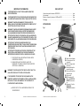
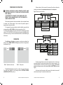
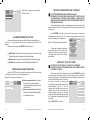
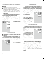
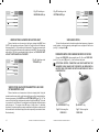
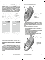
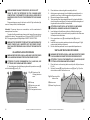
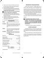
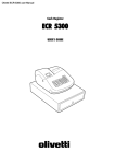
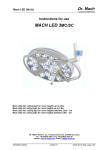
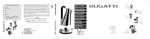
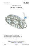
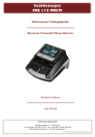
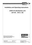
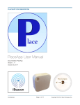
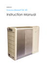
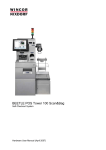
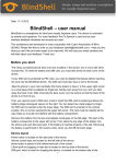
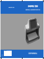
www.dors.com UNIVERSAL COUNTERFEIT DETECTOR Production date: USER MANUAL User Manual Revision 0En CONTENTS PURPOSE....................................................................................................... 4 IMPORTANT INFORMATION......................................................................... 6 DELIVERY SET.............................................................................................. 7 APPEARANCE............................................................................................... 7 PREPARING FOR OPERATION.................................................................... 8 OPERATION................................................................................................... 8 Menu......................................................................................................... 9 Illumination mode selection....................................................................... 10 Video signal source selection..................................................................... 10 Setting of brightness and contrast.............................................................. 11 Setting of auto off timer.............................................................................. 11 Language selection for the menu and information messages..................... 12 UV marks verification................................................................................. 12 IR marks verification.................................................................................. 13 IR blink marks verification.......................................................................... 13 Verification in a white reflected oblique light............................................... 13 Verification in a white reflected light........................................................... 14 Verification in a white transmitted light and IR transmitted light................... 14 Size verification......................................................................................... 15 OPERATION WITH VIDEO MAGNIFIER DORS 1010/1020............................................................................................ 15 OPERATION WITH REMOTE OPTICAL MAGNIFIER DORS 10 AND DETECTOR VISUALIZER OF MAGNETIC AND IR MARKS DORS 15......................................................................................................... 16 VISUAL INSPECTION WITH THE DORS 10................................................... 17 MAGNETIC VERIFICATION WITH THE DORS 15.......................................... 17 RETURN TO THE FACTORY SETTINGS........................................................ 19 SWITCHING OFF THE DEVICE...................................................................... 19 CARE AND MAINTENANCE.......................................................................... 19 UV-LAMP REPLACING PROCEDURE.......................................................... 20 WHITE LAMP REPLACING PROCEDURE.................................................... 21 TROUBLESHOOTING................................................................................... 22 SPECIFICATIONS.......................................................................................... 22 TRANSPORTATION, STORAGE AND DISPOSAL........................................ 23 SUPPORT AND WARRANTY........................................................................ 23 UNIVERSAL COUNTERFEIT DETECTOR DORS 1250 3 We would like to thank you for your choice of Universal Counterfeit Detector DORS 1250. READ THE MANUAL WITH ATTENTION BEFORE YOU START TO WORK! PURPOSE Universal counterfeit detector DORS 1250 (hereafter – ‘the device’) shall be used for a visual detection of authenticity of banknotes, securities, excise stamps and other documents with the protective marks that may be verified by the device. THE DEVICE MAKES POSSIBLE 1. Verifying absence of a general visible luminescence in ultraviolet light on a banknote (document). 2. Verifying presence of IR marks in a reflected and transmitted light as well as verify IR blink marks in two-wave lengths mode (940/850 nm). 3. Verifying a luminescence of the specific areas of a banknote (document) in UV light (marks, security threads and fibers). 4. Verifying watermarks and security threads on banknote (document). Verify an authenticity of micro perforations. 5. Examine the surface of banknotes or documents with protection elements in a white oblique reflected light. This way you can verify the relief of printed elements and a tilting effect. 6. Performing an advanced verification under a 10-fold magnification THE DEVICE IS EQUIPPED WITH ■ An ultra-violet (hereafter – UV) source consisting of 2 fluorescent lamps (6W each); ■ A top infrared (hereafter – IR) light source emitting in the 850-940 nm wavelengths; in two bands (white/IR) when using the video magnifier DORS 1010 or in three bands (white/IR/UV) when using the video magnifier DORS 1020. This way you can verify a coincidence of thin multicolored lines of the currency design, a readability of a microtext and the currency design at specific points. 7. Verify a presence of magnetic marks when using the DORS 15 detector ■ A top white oblique light source; of magnetic and IR marks. ■ A viewing table with a measuring scale and a combined illumination – transmitted IR and white light; ■ 5” touch screen display; ■ A video camera transmitting at 1:1 scale the image of the document on the viewing table to the display; THE DEVICE IS CONTROLLED WITH TOUCH SCREEN MENU. ONCE YOU HAVE READ THE MANUAL, YOU MAY START TO USE THE DEVICE. ■ The connectors for video magnifier DORS 1010, DORS 1020, optical magnifier DORS 10, and a detector of magnetic and IR marks DORS 15. 4 UNIVERSAL COUNTERFEIT DETECTOR DORS 1250 UNIVERSAL COUNTERFEIT DETECTOR DORS 1250 5 IMPORTANT INFORMATION IT IS PROHIBITED TO LOOK AT THE UV-LAMPS DURING THE DEVICE OPERATION. IT IS PROHIBITED TO TOUCH THE DEVICE AND THE POWER CORD PLUG WITH WET HANDS. IT MAY RESULT IN AN ELECTRIC SHOCK. WARNING! TO AVOID ANY DAMAGE OF THE CABLE OR ITS BREAK, UNPLUG THE POWER CORD FROM THE POWER OUTLET BY GET-TING HOLD OF ONLY THE PLUG. WARNING! TO AVOID ANY POWER CORD DAMAGE AND A SHORT CIRCUIT, MOVE THE DEVICE ONLY AFTER THE POWER CORD PLUG HAS BEEN DISCONNECTED FROM THE POWER SUPPLY. DELIVERY SET Universal counterfeit detector DORS1250 ................................................. 1 pcs. User manual ............................................................................................... 1 pcs. Brochure of security features of USD and EUR ......................................... 1 pcs. Packaging................................................................................................... 1 set. APPEARANCE Fig. 1 ATTENTION! THE DEVICE IS TO BE INSTALLED ON A HORIZONTAL PLANE OF A WORKING TABLE. IT IS PROHIBITED TO INSTALL THE DEVICE WITH ITS UV-LAMPS BEING VISIBLE FOR THE OPERATOR. ATTENTION! IF THE DEVICE HAS BEEN UNDER COLD CONDITIONS FOR A LONG TIME, IT SHALL BE KEPT UNDER ROOM TEMPERATURE FOR NOT LESS THAN TWO HOURS BEFORE ITS SWITCHING ON. ATTENTION! TO PROVIDE A SUCCESSFUL OPERATION OF THE DEVICE FOR A LONG TIME WITHOUT A SERVICE ENGINEER INTERFERENCE, OBSERVE THE FOLLOWING RULES, PLEASE: 1. THE D EVICE SHALL BE INSTALLED ON AN EVEN HORIZONTAL SURFACE; 2. WHEN INSTALLING THE DEVICE, AVOID ITS EXPOSURE TO DIRECT SUNLIGHT AND DIRECTED ARTIFICIAL ILLUMINATION. Touch screen display; UV-lamp (one of two is shown); Slot for a large-sized document; Viewing table with a measuring scale; Power switch with an indicator light; Power cord; , Connectors M1, M2 for the DORS 10 (DORS 15) connection; Connector V for the DORS 1010 (DORS1020) connection. WARNING! TO AVOID AN ELECTRIC SHOCK, APPLY ONLY TO A QUALIFIED SPECIALIST TO REPLACE THE LAMPS. IT IS PROHIBITED TO DISPOSE THE USED LAMPS IN THE DOMESTIC GARBAGE CONTAINERS. AFTER A LAMP HAS BEEN REPLACED, IT SHALL BE HANDED IN TO THE SERVICE OF FLUORESCENT LAMPS DISPOSAL. DEVICE WITH ITS UV-LAMPS BEING VISIBLE FOR THE OPERATOR 6 UNIVERSAL COUNTERFEIT DETECTOR DORS 1250 UNIVERSAL COUNTERFEIT DETECTOR DORS 1250 7 PREPARING FOR OPERATION BEFORE THE DEVICE OPERATION STARTS, MAKE ATTENTION! SURE ABOUT INTEGRITY OF ITS BODY AND THE THREE FLUORES- Further touching of the free area of the screen will result in an alternative switching over between the operation mode menu and the setup menu. Fig. 4 Shows the menu hierarchy. CENT LAMPS . IT IS PROHIBITED TO CONNECT TO THE POWER SUPPLY THE PRODUCT WITH A DAMAGED BODY, WITH THE DAMAGED UVLAMPS OR WITHOUT THEM. When selecting a place for the device installation, the most optimal location (in relation to the viewing angles) is the one when the operator's glance is perpendicular to the screen surface. If it is supposed to use external devices, the latter shall be connected to the corresponding jacks (, or ) on the device rear panel (see Fig. 1). To start the device operation, the power cord shall be connected to the power socket of 110-240 VAC 50/60 Hz. After that press the power switch () to switch on the device (see Fig.1). A built-in red indicator shall turn on to show switching on of the device. OPERATION MODE MENU VIDEO VIDEO CAMERA VIDEO INPUT WHITE BOTTOM WHITE TOP WHITE OBLIQUE WHITE WHITE OFF IR IR IR BLINK UV UV 365 NM UV OFF SETUP MENU OPERATION At switching on the device, an operation mode menu containing four buttons, such as VIDEO, WHITE, IR, UV appears by default in the upper part of the display (see Fig. 2). VIDEO WHITE IR UV BUTTONS IMAGE LANGUAGE AUTO OFF BUTTONS SHOW HIDE LANGUAGE IMAGE BRIGHTNESS CONTRAST OK CANCEL AUTO OFF 1 MINUTE 3 MINUTES 10 MINUTES 30 MINUTES DISABLE MENU Рис. 2. Operation mode menu Рис. 3. Setup menu To select a desired mode, choose the required menu item on the screen according to fig. 4. Then select the required mode in the chosen menu item. The selected mode will be marked by the check sign in the submenu. To hide the menu from the display screen, select the option Hide in the BUTTONS menu (see Fig. 5). To enter the setup menu, touch with your finger a free area of the screen. The setup menu consists of the following buttons: BUTTONS, SCREEN, LANGUAGE, AUTO OFF (see Fig. 3). In this case, touch the screen to call the menu. In this mode the screen will show the menu during 5-7 seconds since the last touch. 8 UNIVERSAL COUNTERFEIT DETECTOR DORS 1250 UNIVERSAL COUNTERFEIT DETECTOR DORS 1250 9 BUTTONS IMAGE LANGUAGE AUTO OFF Fig. 5. How to switch on the mode with hidden buttons SHOW HIDE ILLUMINATION MODE SELECTION To select the illumination mode, you shall be in the operation mode menu (see Fig. 2). If it is necessary, call this menu by touching the free area of the screen. Select one of the menu items: WHITE, IR or UV (see Fig. 2). WHITE mode either switches on the top white, or the bottom white light or white oblique light or switches off any white light mode. IR mode switches on either the infrared light or the IR blink marks mode. UV Mode either switches on ultraviolet light or switches it off. VIDEO SIGNAL SOURCE SELECTION Select the VIDEO item in the operation mode menu. Select the required video signal mode (see Fig. 6) in the pop-up submenu: Fig. 6. Video signal source selection VIDEO VIDEO CAMERA VIDEO INPUT WHITE IR UV Video camera mode calls to the screen the image from the device's built-in camera corresponding to the light mode selected before; Video input mode displays the image from the connected video magnifier on the device screen. SETTING OF BRIGHTNESS AND CONTRAST ATTENTION! BRIGHTNESS AND CONTRAST ARE SET SEPARATELY FOR EACH VIDEO SIGNAL SOURCE. THE SET VALUES OF BRIGHTNESS & CONTRAST ARE STORED IN A NONVOLATILE MEMORY AND USED DURING THE NEXT OPERATION WITH THE THIS VIDEO SIGNAL SOURCE. To enter the brightness or/and contrast adjustment mode, you shall be in the setup menu (see Fig. 3). If it is necessary, call this menu by touching the free area of the screen. Press SCREEN. It will call to the screen the current values of the image brightness and contrast (see Fig. 7). To set the image brightness and contrast, press + (to increase) or – (to decrease). BUTTONS Fig. 7. Setting of brightness and contrast IMAGE LANGUAGE AUTO OFF BRIGHTNESS 105 To save the set values of brightness and contrast, press Yes. To return to the upper level submenu without saving the set values (return to the previous values), press Cancel. CONTRAST 135 OK CANCEL SETTING OF AUTO OFF TIMER ATTENTION! THE SETTINGS OF THE AUTO OFF TIMER ARE STORED IN A NONVOLATILE MEMORY AND USED THEREAFTER AS THE DEFAULT VALUES. To set an auto off interval, call the setup menu. Press AUTO OFF in the setup menu the current value of the auto off timer will be shown (see Fig. 8). Select the required auto off interval. The selected value is immediately saved in the memory, without any additional pressing. If the autooff mode is selected, the device goes BUTTONS IMAGE LANGUAGE AUTO OFF automatically to the standby mode after the 1 MINUTE specified period of time (1, 3, 10 or 30 3 MINUTES minutes), after the last screen touch. in a standby mode, all the light sources, the 10 MINUTES display backlight and most of the other 30 MINUTES power consumers of the device get switched DISABLE off. To wake from the standby mode, touch the display. Fig. 8. AUTO OFF timer setting 10 UNIVERSAL COUNTERFEIT DETECTOR DORS 1250 UNIVERSAL COUNTERFEIT DETECTOR DORS 1250 11 LANGUAGE SELECTION FOR THE MENU AND INFORMATION MESSAGES ATTENTION! LANGUAGE SETTINGS OF THE MENU AND INFORMATION MESSAGES ARE STORED IN A NONVOLATILE MEMORY AND USED LATER ON AS THE DEFAULT ONES. BE CAREFUL AND AVOID TO SET A LANGUAGE YOU FAIL TO UNDERSTAND. THE NEXT OPERATION WITH THE THIS VIDEO SIGNAL SOURCE. To select the menu language, you shall be in the setup menu (see Fig. 3). If it is necessary, call this menu by touching the free area of the screen. Select the LANGUAGE item. The currently used language is marked by the check sign (see Fig. 9). Select the required interface language by pressing the corresponding menu item. To return to the upper level menu without change, touch any free area of the screen. BUTTONS IMAGE LANGUAGE AUTO OFF Fig. 9. Language selection menu ENGLISH IR MARKS VERIFICATION The device goes to the IR light mode any time when it is switched on or exits waked from the stand-by mode. The IR light does not switch off at switching on the other types of illumination (UV, all types of white light). Therefore, a simultaneous use of several types of control is possible since any type of control is combined with IR verification. If you need the IR-mode only, without any other light, select the IR item in the IR submenu of the operation WHITE IR UV VIDEO mode menu (see Fig. 11). Fig. 11. IR light switching on IR BLINK Place a banknote or a document on the device viewing table (). Use the on-screen menu to set (if required) the desirable brightness and contrast of the image on the display. Observe the image of the IR-marks on the display screen. IR BLINK MARKS VERIFICATION РУССКИЙ Place a banknote or a document on the device viewing table (). Press IR in the operation mode menu. Select the IR BLINK item in the opened submenu (see Fig. 12). УКРАИНЬСКА ҚАЗАҚ 中国的 Fig. 12. Switching on the IR blink marks mode UV MARKS VERIFICATION IT IS PROHIBITED TO LOOK AT THE UV-LAMPS DURING THEIR OPERATION. Place a banknote or a document on the device viewing table (). Press UV in the operation mode menu (see Fig. 2). Select the UV 365 nm item in the opened submenu (see Fig. 10). The UVmarks on the document surface. WHITE IR UV VIDEO UV 365 NM Fig. 10. UV light switching on UV OFF 12 IR UNIVERSAL COUNTERFEIT DETECTOR DORS 1250 The document on the device viewing table shall avoid direct sunlight or the light from the powerful incandescent lamps. Otherwise, it will be difficult to examine IR blink marks. The IR blink marks should clearly blink with an interval of about 2 times per second. VIDEO WHITE IR UV IR IR BLINK VERIFICATION IN A WHITE REFLECTED OBLIQUE LIGHT Place a banknote or a document on the device viewing table (). Press WHITE in the operation mode menu. Select the Oblique white item in the submenu that opened (see Fig. 13). The mode is convenient, for example, for viewing the tilting effect on notes of different currencies. This mode makes possible to verify the height of the printed elements because they cast a clear shadow in an oblique light. The source of top white light is LED with a considerably high brightness, so PLEASE DO NOT LOOK AT THE TOP WHITE LIGHT SOURCE. UNIVERSAL COUNTERFEIT DETECTOR DORS 1250 13 VIDEO WHITE IR UV Fig. 13. Switching on WHITE OBLIQUE light Fig. 15. Switching on the BOTTOM WHITE light VIDEO WHITE IR BOTTOM WHITE BOTTOM WHITE TOP WHITE TOP WHITE OBLIQUE WHITE OBLIQUE WHITE WHITE OFF WHITE OFF UV VERIFICATION IN A WHITE REFLECTED LIGHT SIZE VERIFICATION Place a banknote or a document on the device viewing table (). Press WHITE in the operation mode menu. Select the Top white item in the submenu that opened (see Fig. 14) to switch on the illumination. This mode is convenient for control of the protective elements with variable color inks (OVI). The source of top white light is LED with a considerably high brightness, so PLEASE DO NOT LOOK AT THE TOP WHITE LIGHT SOURCE. To check the dimensions of a banknote as whole and accuracy of separate marks location, use the measuring scale applied on a matt glass of the device (see Fig. 1) viewing table (). VIDEO WHITE IR UV Fig. 14. Switching on the TOP WHITE light BOTTOM WHITE TOP WHITE OBLIQUE WHITE OPERATION WITH VIDEO MAGNIFIER DORS 1010/1020 Connect the DORS 1010 video magnifier (see Fig.16) or the DORS 1020 (see Fig.17) to jack V () (see Fig. 1) on the device rear panel. ATTENTION! BEFORE CONNECTING AND DISCONNECTING THE MAGNIFIER CABLE, MAKE SURE THE DEVICE HAS BEEN DISCONNECTED FROM THE POWER SOCKET OR SWITCHED OFF WITH A POWER SWITCH! WHITE OFF VERIFICATION IN A WHITE TRANSMITTED LIGHT AND IR TRANSMITTED LIGHT Place a banknote or a document on the device viewing table. Using the operation mode menu, switch on the bottom light source of the viewing table by a successive pressing of the WHITE and the BOTTOM WHITE (see Fig. 15). The source of the bottom light simultaneously emits white light and IR light. The mode is convenient for verification of the watermarks and imprinted metalized stripes with pictures etc. The screen shows IR image of both sides of a banknote (document). It makes possible to examine watermarks with better contrast as well as the marks on the metalized stripes (this mode is especially convenient to detect Euro banknotes). 14 UNIVERSAL COUNTERFEIT DETECTOR DORS 1250 «LIGHT-SELECT» key «SELECT» key Fig.16. Video magnifier DORS 1010 Fig.17. Video magnifier DORS 1020 UNIVERSAL COUNTERFEIT DETECTOR DORS 1250 15 Switch on the device. Press the LIGHT-SELECT key () (in case of the DORS 1010) or SELECT () (in case of the DORS 1020) on the top of a magnifier. The device automatically switches to the mode of image examination with a magnifier. Further pressing of the same key selects a light source. The DORS 1010 magnifier has two light sources: white and IR, and the DORS 1020 magnifier has three sources: white, IR and UV. The model of the connected magnifier and its selected light mode are shown in the top part of the screen. VISUAL INSPECTION WITH THE DORS 10: To switch the device to a built-in camera, select the VIDEO item in the operation mode menu and then the Video camera (see Fig. 18). To return to operation with the video magnifier, press respectively the LIGHT-SELECT or the SELECT key ( or ) or select the Video input item in the VIDEO submenu (see Fig. 19); a message will appear in the top part of the screen saying about the necessity to set the required light mode of the connected magnifier. VIDEO WHITE IR UV VIDEO VIDEO CAMERA VIDEO CAMERA VIDEO INPUT VIDEO INPUT WHITE IR UV Fig. 20. Optical magnifier DORS 10 Eye-lens Lightning ON key When DORS 10 magnifier (see Fig. 20) is used, the device itself may be in any operation mode. Place the lens () of the DORS 10 magnifier above the area of the banknote to be examined (the banknote shall be on a plane horizontal surface). MAGNETIC VERIFICATION WITH THE DORS 15: 1. 2. Fig. 18. Switching on the operation mode with the device built-in camera Fig. 19. Switching on the operation mode with a video magnifier 3. 4. When detector DORS 15 (see Fig. 21) is in use, the operation mode of the device itself may be any. The device and the banknote to be examined should be on a special mat for verification (included in the delivery set of the DORS 15). Press any key (, ) to switch on the DORS 15. A short pressing of the SELECT key () selects the magnetic verification mode (built-in LED is lighted in green color). Fig. 21. Detector of magnetic and IR marks DORS 15 OPERATION WITH REMOTE OPTICAL MAGNIFIER DORS 10 AND DETECTOR VISUALIZER OF MAGNETIC AND IR MARKS DORS 15 «SELECT» key «VOLUME» key Sensor Connect the DORS 10 magnifier and (or) the DORS 15 detector to either jack M1 or jack M2 (), () (see Fig. 1) on the device rear panel. The device itself must be connected to the power supply and switched on or remained in a standby mode. A simultaneous connection of both devices (the DORS 10 and the DORS 15) is also possible. Operation with the DORS 10 and the DORS 15 is described hereinafter. 16 UNIVERSAL COUNTERFEIT DETECTOR DORS 1250 UNIVERSAL COUNTERFEIT DETECTOR DORS 1250 17 Put the DORS 15 on a banknote in such a way that the area to be examined is under the sensor (). Moving the sensor along the area to be examined, determine the places where the sensor is triggering and non-triggering. A sound signal and a glowing indicator inform about the sensor triggering. The sound signal may be switched ON/OFF at any moment of operation. To switch it off, press the VOLUME key () and () SELECT key; () VOLUME key () Sensor The places where the sensor is triggering are magnetic, and where it's nontriggering are non-magnetic. Thus, location of the magnetic and non-magnetic inks of the text and the drawings is detected with a high accuracy. 5. The obtained data shall be compared with the location of the magnetic marks on an authentic banknote (this information is usually available on the web site of the appropriate Central (National) Bank). ATTENTION! THE MAGNETIC SENSOR OF THE DORS 15 IS DISTINGUISHED WITH HIGH SENSITIVITY; THAT IS WHY ANY SWITCHED ON MOBILE PHONE WITHIN THE RANGE OF 2.5 M FROM THE DEVICE MAY CAUSE THE DEVICE'S ERRORS. Note: If the marks are not clearly detected during verification, it is necessary to adjust the sensitivity. It is caused by a wide variation of the magnetic characteristics among banknotes of different currencies. Beside this, banknotes of the same type may also differ significantly because of the printing technological peculiarities and due to their wear and tear and blotting during circulation. If it's necessary to change the sensitivity, press shortly the VOLUME key () to select the required sensitivity level. The red illumination of the VOLUME key corresponds to the highest sensitivity, yellow to the middle sensitivity and green to the lowest one. Being switched on the detector goes to the mode in which it was before the last switching off. If the DORS 15 is activated in the areas devoid of magnetic marks, repeat the examination with the lowest sensitivity mode. If even now the device is activated on the banknote's non-magnetic areas or ceased on the magnetic ones, the banknote may be counterfeited and requires examination according to the other marks. If the problem does not exist any more, the banknote is authentic but it may has some printing defects. It is recommended to set the highest sensitivity level to verify the worn banknotes with vague magnetic properties: The Euro, US dollars etc. To avoid false triggering, do not touch either the sensitive element or the metal parts, avoid any mechanical impact on the sensor. 18 UNIVERSAL COUNTERFEIT DETECTOR DORS 1250 To switch off detector DORS 15, press and hold the SELECT key () during 3 s. If the DORS 15 is not used during an hour, it switches off automatically. RETURN TO THE FACTORY SETTINGS If it is necessary, you may reset all the device settings that have ever been done and return to the factory ones. To do it, touch with your finger the free area of the screen and hold it for 5 s; then there will appear the menu of return to the factory settings that also indicates the current software (firmware) version of the device (see Fig. 22). If you want to return to the factory settings, select Yes, if not, choose Cancel. Fig. 22. Return to the factory settings FIRMWARE VER 1.2 RETURN TO FACTORY SETTINGS YES CANCEL SWITCHING OFF THE DEVICE Press the power switch key () (see Fig. 1), its backlight will be turned off. It is up to the user to decide whether to disconnect the power cord from the power supply or not. It is certainly worth of disconnecting in case of a long-term (more than several days) standing by of the device. If it is necessary to install the device on a new place after it was switched off, disconnect the power plug from the power socket. After that you may move the device to a new place. CARE AND MAINTENANCE To clean the device surface from dirt, use water-based neutral detergents or the cleaning agent on the base of isopropyl alcohol. Remove carefully an excess of the detergent or the cleaning agent from the device. WARNING! BEFORE CLEANING THE DEVICE SURFACE FROM DIRT, MAKE SURE THE POWER PLUG HAS BEEN REMOVED FROM THE POWER SOCKET! WARNING! TO AVOID AN ELECTRIC SHOCK, PREVENT A PENETRATION OF THE DETERGENT OR THE CLEANING AGENT INSIDE THE DEVICE! UNIVERSAL COUNTERFEIT DETECTOR DORS 1250 19 WARNING! WHEN CLEANING THE SURFACE, USE ONLY A SOFT TISSUE TO APPLY THE DETERGENT OR THE CLEANING AGENT COMPOSITION! IT IS PROHIBITED TO USE A BRUSH, ASPRAYER OR AN AEROSOL SPRAY TO APPLY THE DETERGENT OR THE CLEANING AGENT 2. 3. 4. 5. Fluorescent lamps are used in the device as the UV light and bottom light sources. If a lamp is failed, it shall be replaced. Attention! Fluorescent lamps are consumables, and the manufacturer's warranty doesn't cover them. 6. To replace the fluorescent lamps, please use the lamps of the same type as installed in the device. The suggested type of UV lamp is DORS TL 6W/08 F6T5/ BLB. The suggested type of white light lamp is DORS TL 6W/08 F6T5/DL. 7. WARNING! IT IS PROHIBITED TO REPLACE THE LAMPS WHEN IN THE DEVICE POWER PLUG IS INSERTED INTO THE POWER SOCKET. ONLY QUALIFIED PERSONNEL SHALL REPLACE THE LAMPS IN THE DEVICE. 8. 9. WARNING! BEFORE REPLACING A LAMP, MAKE SURE THE POWER PLUG HAS BEEN DISCONNECTED FROM THE POWER SOCKET! WARNING! BEFORE REPLACING A LAMP, MAKE SURE THE POWER PLUG HAS BEEN DISCONNECTED FROM THE POWER SOCKET! Fig. 23. Removing of the UV-lamp protection cover UV-lamps Protection cover catch UV-lamp holder UV-lamp protection cover 20 UNIVERSAL COUNTERFEIT DETECTOR DORS 1250 ATTENTION! DO NOT INSTALL IN THE DEVICE A LAMP HAVING MECHANICAL DAMAGES AND BULB CONTAMINATION! Insert the lamp into the holders up to the stop. Holding the lamp by two fingers of both hands, turn it around its axis by a quarter of a turn. Make sure the lamp has fixed in the holders. Put on a protection cover () on each lamp holder () (no tool is required). Install the device in a working position and make a trial turning on UV light, make sure that the failure is recovered. Pack the failed lamp and hand it over to a specialized disposal service. WHITE LAMP REPLACING PROCEDURE UV-LAMP REPLACING PROCEDURE ATTENTION! TO AVOID CONTAMINATION OF A GLASS BULB, USE COTTON GLOVES DURING LAMP REPLACEMENT. 1. You should remove the failed lamp together with its protection covers () out of the holders () (see Fig. 23). Place the device on the working table covered by soft cloth. Applying no excessive strength, turn the failed lamp around its axis for a quarter of a turn. Doing it, hold the lamp with two fingers of both hands. Remove the lamp protection covers (). Take a new lamp from the package and inspect it: the glass bulb shall be devoid of scratches and chipping, the lamp cap shall not be damaged, and the glass bulb surface shall be not contaminated. 1. 2. ATTENTION! TO AVOID CONTAMINATION OF A GLASS BULB, USE COTTON GLOVES DURING LAMP REPLACEMENT. Place the device on the working table covered by soft cloth (as shown on Fig. 24). Unscrew 4 screws () fixing the bottom cover () (see Fig. 24) on the device bottom surface. Remove the cover. Fig. 24. Removing of the bottom cover Bottom cover Screws fixing the cover UNIVERSAL COUNTERFEIT DETECTOR DORS 1250 21 3. 4. 5. 6. 7. 8. 9. Applying no excessive strength, turn the failed lamp around its axis for a quarter of a turn. Doing it, hold the lamp with two fingers of both hands. Remove the failed lamp out of the lamp holders. Take a new lamp from the package and inspect it: the glass bulb shall be devoid of scratches and chipping, the lamp cap shall not be damaged, and the glass bulb surface shall be not contaminated. ATTENTION! DO NOT INSTALL INTO THE DEVICE A LAMP HAVING MECHANICAL DAMAGES AND BULB CONTAMINATION! Insert the lamp into the holders up to the stop. Holding the lamp with two fingers of both hands, turn it around its axis by a quarter of a turn. Make sure the lamp is fixed in the holders. Install the cover in its place and screw in the screws up to their stop. Install the device in a working position and make a trial turning on of UVradiation; make sure the failure is recovered. Pack the failed lamp and hand it over to a specialized disposal service. TROUBLE: SUGGESTION: TROUBLE: SUGGESTION: TROUBLESHOOTING The device fails to switch on (the power switch key doesn't light). Check the device connection to the power supply. If the device is connected, a fuse F1 (2.0A, 250V) on the CPU power board has failed. Apply to your supplier (or authorized service center). There is no picture from an external video magnifier / there is no switch to the corresponding video input by pressing the Select key on the magnifier. The magnifier connector might be not completely inserted in the V jack () of the device (see Fig. 1). Insert the connector into the jack till it stops. SPECIFICATIONS Supply voltage ...............................................................100 – 240 VAC, 50/60 Hz Current consumption..........................................................................0.4 – 0.17 A Weight (not more than) ................................................................................2.3 kg Overall dimensions (Width x Depth x Height): ...........................264x155x222 mm UV-radiation source total power....................................................................12 W UV-radiation peak wavelength .................................................................365 nm IR-radiation operating range ..........................................................800 – 1000 nm Two wavelengths in IR blink mode......................................................850/940 nm Video signal standard.....................................................................................PAL Linear magnification on display: at the use of the DORS 1010......................................11x at the use of the DORS 1020 .....................................22x Operating temperature.......................................................................+5 to +40оC 22 UNIVERSAL COUNTERFEIT DETECTOR DORS 1250 TRANSPORTATION, STORAGE AND DISPOSAL The device shall be transported in a standard package by sea (in containers), railway (in closed wagons), air (in a pressurized baggage or a cargo compartment) and motor (in an enclosed body or in a container under a waterresistant canopy along the public paved roads) transport. The transportation conditions: temperature – 30 to + 50°C, relative humidity up to 95 % without water condensation at +25°C, atmosphere pressure 84 to 107 kPa (630 to 800 mm Hg). The device shall be stored in the package, in a heated warehouse at tempera- ture +10 to +25°C, at a relative air humidity not exceeding 80%. The device meets the requirements of the European Union RoHS directive which results in decrease of the environmental pollution by hazardous substances. ATTENTION! BEFORE DISPOSAL, REMOVE ALL THE THREE FLUORESCENT LAMPS FROM THE DEVICE IN COMPLIANCE WITH THE ITEMS 1 – 4 OF THE SECTIONS «UV-LAMP REPLACEMENT PROCEDURE» AND «WHITE LAMP REPLACEMENT PROCEDURE». THE REMOVED LAMPS SHALL BE HANDED OVER TO A SPECIALIZED DISPOSAL SERVICE*. * – The device without its lamps may be disposed as a domestic waste. SUPPORT AND WARRANTY The manufacturer guarantees a 12 month of the device operation since the moment of its purchase. The manufacturer by means its local dealer is obliged to repair the failed device if the user has observed all the requirements of this User manual. Failure of the fluorescent lamps is not covered by warranty since they are consumables. The device damage caused by its improper use, falling, applying of an excessive physical strength and ingress penetration of liquid and foreign objects into the device. UNIVERSAL COUNTERFEIT DETECTOR DORS 1250 23