1
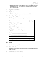
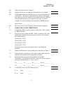
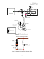
P0536 Rev. A
September 11, 2000
STANFORD UNIVERSITY
W.W. HANSEN EXPERIMENTAL PHYSICS LABORATORY
GRAVITY PROBE B, RELATIVITY GYROSCOPE EXPERIMENT
STANFORD, CALIFORNIA 94305-4085
ROOM-TEMPERATURE TEST OF
CAGING SYSTEM IN PROBE C
GP-B SCIENCE MISSION PROCEDURE
P0536 Rev-A
September 11, 2000
PREPARED
_______________________________________
R. Brumley, Gyroscope RE
_________________
Date
APPROVED
_______________________________________
J. Mester, Caging System RE
_________________
Date
APPROVED
_______________________________________
C. Gray, Gyroscope Verification
_________________
Date
APPROVED
_______________________________________
D. Ross, Quality Assurance and Safety
_________________
Date
APPROVED
_______________________________________
B. Muhlfelder, Technical Manager
_________________
Date
1
P0536 Rev. A
September 11, 2000
REVISION HISTORY
Rev
Date
-
07/11/99
A
09/11/00
Comments
Change procedure to incorporate minor redlines from the previous run.
Main structure of the procedure has not been changed.
2
P0536 Rev. A
September 11, 2000
1.
SCOPE
This procedure is intended to be used to verify the functionality of the caging
system as part of the room-temperature checkout of Probe C prior to the
cryogenic acceptance testing. It may be used at other stages of probe acceptance
testing if so desired. This procedure is only intended to verify basic functionality
of the system (i.e. that the gyroscope cages and uncages). It does not seek to
measure any basic parameters of the caging process. Note that the DDC must be
installed per procedure P0481 before performing this procedure.
2.
REFERENCES
2.1
Plans and Procedures
P0481
Levitation of Gyroscopes in Probe C
P0505
RT Spinup of Gyroscopes in Probe C
P0410
Pumpdown and leak check
3.
GENERAL REQUIREMENTS
3.1
Environmental Requirements
3.1.1 Cleanliness
This procedure takes place in the Class 1000 cleanroom in the HEPL building.
Minimum protective garments for personnel working in the clean rooms shall be
the standard Tyvek clean room apparel. All activities taking place within this
room must be in accordance with the guidelines established by the cleanroom
manager.
3.1.2 Particulate Contamination
All connectors shall be inspected and verified free of particulate contamination
before they are mated to Probe C. It is also desirable to keep the probe in general
clean and free of particulate contamination.
Note: The caging lines have an I.D. of 5 milli-inches. It is therefore very easy
to clog the lines should any contamination be present. Great care must be
taken to ensure that no particles get into the caging lines.
3.1.3 Magnetic Contamination
This procedure takes place after the vacuum can is sealed, making the experiment
much less sensitive to magnetic contamination. However, great care shall still be
taken to avoid cross contamination between any magnetic (e.g. steel) item and the
3
P0536 Rev. A
September 11, 2000
probe, particularly on the probe's "cold" end. Therefore no magnetic items may
be used in the immediate vicinity of the "cold" end of the probe.
3.2
Test Personnel
3.2.1 Test Director
The test director for this procedure shall be Robert Brumley, or his appointed
replacement.
3.2.2 Personnel
The following personnel have received the training necessary to perform this
procedure.
•
•
•
•
•
•
David Hipkins
Bruce Clarke
Chris Gray
Robert Brumley
Dr. John Mester
Dr. Sasha Buchman
See section 3.4 for details on the requirements for Quality Assurance notification
and witnessing of this procedure.
3.2.3 Minimum Personnel
No activity shall be performed on the science mission probe without at least two
people in the room, i.e. at least one person to perform the procedure and one
person to observe the procedure.
3.3
Safety
3.3.1 Hardware Safety -- General
It is important to be cognizant at all times of the position of the probe. Be
extremely careful not to accidentally bump into the probe. If any connector does
not connect smoothly and securely, do not try to force it. Instead, remove the
connector and inspect it to find the reason for the difficulty. Great care must be
taken at all times during the performance of this procedure.
3.3.2 Electrostatic Discharge
Grounded wrist straps shall be worn at all times when mating or demating to an
electrical connector on Probe C.
4
P0536 Rev. A
September 11, 2000
3.3.3 Personnel Safety
All operations shall take place according to Stanford University safety guidelines.
Any person observing a situation which they deem unsafe shall report the fact
immediately to the test director. The Quality Assurance representative shall be
responsible for monitoring that all activities are performed in a safe manner.
3.4
Quality Assurance
•
Stanford QA must be notified at least 24 hours before beginning this
procedure.
•
ONR QA must be notified at least 24 hours before beginning this procedure.
•
D. Ross (or her designate) must be present to monitor the completion of this
procedure.
This procedure shall be conducted on a formal basis to its latest approved and
released version. The QA Program Engineer shall be notified of the start of this
procedure. A Quality Assurance representative designated by D. Ross shall
review any discrepancy noted during test. Redlines shall be approved by the QA
representative. The QA representative will nominally be Russ Leese. Upon
completion of this procedure, the QA Program Engineer, D. Ross or R. Leese,
shall certify his or her concurrence that the effort was performed and
accomplished in accordance with the prescribed instructions by signing and dating
the appropriate approval line at the end of the procedure.
3.5
Red-Line Authority
Authority to red-line (make minor chances during execution) this procedure is
given to the qualified personnel listed in section 3.2.2. All redlines must be
approved by the QA representative. In addition, approval by the Hardware
Manager shall be required if, in the judgement of the test director or the QA
representative, experiment functionality may be affected.
3.6
Electrical Connections
When mating to any flight connector, the following items are required:
•
A grounded ESD strap must be worn by any person handling a connector on
Probe C
•
Inspect both connectors being mated to ensure that there are no particles that
might interfere with the mate.
5
P0536 Rev. A
September 11, 2000
•
Each mate and demate of flight connectors must be logged in that connector's
mate/demate log sheet. Note that these log sheets have already been started
for all suspension lines.
4.
REQUIRED EQUIPMENT
4.1
Flight Hardware
•
4.2
Probe C assembly with vacuum can installed, no sunshade.
Ground Support Equipment
The following equipment is necessary to perform these tests.
Item
Quantity
GSE plumbing assembly for caging
1
Bottle of ultra-pure He
1
Gaskets for VCR fittings (connector savers for
flight gammah connections)
3
Digital Multimeter capable of reading resistances
>200 MΩ.
1
Model: __________________________________
S/N: ____________________________________
DDC-Probe C Interface Box
1
DDC Suspension System
4.3
1 / gyro testing
Software
No software is necessary for this procedure.
4.4
Tools and Miscellaneous
Fluke meters and capacitance meters shall be readily available should the need to
trouble shoot arise.
5.
GUIDELINES FOR OPERATIONS
6
P0536 Rev. A
September 11, 2000
•
This procedure may be completed with the probe either at atmospheric pressure or in
high vacuum.
•
This procedure should be completed for each gyroscope in the probe.
•
Note that the DDC must be installed per P0481 before performing this procedure.
•
Gyroscopes 1 and 2 can be tested separately
•
Note that the same line feeds both gyroscopes #3 and #4. Therefore both gyroscopes
cage at the same time. However, there are two valves that feed this one line. Both of
these valves need to be checked.
•
This procedure leaves the option for either a full cage (160 psi) or a partial cage
"touch test" (~40 psi)
6.
INITIAL SETUP
6.1
Enter the following data:
Start Date: _____________________
Start Time: _____________________
Gyroscope(s) #: ___________________
Note: Gyroscopes 3 and 4 are automatically caged at the same time.
6.2
Assemble all equipment on the Equipment list in Section 4
6.3
Turn on and prepare the leak detector for test. This should be done in
accordance with its user manual.
6.4
Purge the caging GSE for at least 5 minutes by opening V1, V2, V3,
V5, V6 and the metering valve. V4 (the vent valve) should be closed.
6.5
Set the regulator on the He supply to 165 psid.
Note: One should not exceed 185 psi on the caging assembly. Since
the probe will be evacuated, 185 psi on the caging assembly = 185 –
14.7 ~ 170 psi on a gauge. Therefore the regulator on the He supply
is set to 165 to provide some safety margin.
6.6
Close the regulator on the caging GSE enough so that a very light flow
of He is still present.
6.7
Connect the GSE plumbing to probe C and the leak detector per Figure
1. Note that Figure 1 contains the proper valve designation. Record
here:
7
P0536 Rev. A
September 11, 2000
Line Designation = CG_____
6.8
Set the valves to the following states:
(Open means gas can flow through the valve, Closed means gas can not
flow through the valve)
V1 ⇐
Open
_______
V2 ⇐
Open
_______
V3 ⇐
Open
_______
V4 ⇐
Closed
_______
V5 ⇐
Open
_______
V6 ⇐
Open
_______
V7 ⇐
Open
_______
V8 ⇐
Closed
_______
Metering Valve
⇐
Closed
_______
GSE regulator
⇐
Closed
_______
Open at 165 psi
_______
He bottle regulator ⇐
6.9
Prepare to open the valve on the caging line of Probe C.
6.10
To be completed if caging lines are currently under vacuum
Cycle the leak detector to test mode per the instructions in its user
manual. Pump on the caging assembly until the base pressure goes
below 10-3 torr. Open the relevant caging valve on the probe. Go to step
6.12 (skip 6.11)
6.11
To be completed if caging lines are currently at atmosphere
Open the relevant caging valve on the probe.
(Optional) It is now permitted to pump on the caging line and GSE with
the leak detector. This step need only be performed if (a) there is a
desire to leak check the portion of the caging lines outside the vacuum
can, or (b) it is desired to eliminate any N2 in the lines prior to a
cryogenic insertion.
8
P0536 Rev. A
September 11, 2000
Check if line was pumped on: ______________
6.12
OPTIONAL CHECK FOR CAGING LINE TO WELL LEAKS
If the lines are being pumped on with the leak detector according to 6.10
or the optional component of 6.11, it is now possible to perform a leak
check on the portions of the caging lines that are outside the vacuum
can. Record Results in Table 1.
Check if done: ____________________
9
P0536 Rev. A
September 11, 2000
TABLE 1 (OPTIONAL): CAGING LINE LEAKAGE RATE CHECK
(Caging Line to Well Leaks)
Caging Line CG_____________
Time
Port Pressure
He Rate
Notes
10
P0536 Rev. A
September 11, 2000
TABLE 1 (OPTIONAL): CAGING LINE LEAKAGE RATE CHECK
(Caging Line to Well Leaks)
Time
Port Pressure
He Rate
Notes
11
P0536 Rev. A
September 11, 2000
6.12
Isolate the leak detector by closing V7.
6.13
Vent the leak detector according the instructions in its user manual.
6.14
(Optional) Re-connect the leak detector to its test port on the pumping
system (LTV). This allows a leak check of the portions of the caging
lines which sit inside the vacuum can (by monitoring the rate of He rise
in the can when the lines are pressurized for the cage). To do this,
configure the system according to the instructions of P0410 Section 7.
Check if done: ____________________
6.15
The system is now ready to begin pressurization of the caging line.
7.
GYROSCOPE CAGING VERIFICATION
7.1
Verify that the DDC is already connected to the probe. If not, connect
per P0481 Section 6.
7.2
If not already done, connect the DDC - Probe C connector saver to the
ground plane connection for the gyroscope of interest. For reference,
these connections are:
Gyroscope #1: CG18
Gyroscope #2: CG28
Gyroscope #3: CG38
Gyroscope #4: CG48
Note that static protection wrist bands must be worn during this
procedure.
7.3
Connect the Electrometer to the ground plane connection per Figure 2.
7.4
Connect the other electrometer lead to probe ground (which should be
identical to the potential of the caging fixture potential).
7.5
Record the initial (uncaged) position indicated on the DDC
(microinches). Note that the second line is only to be used if caging two
gyroscopes simultaneously (i.e. Gyros 3 and 4)
X = _________ Y = _________ Z = _________ Gyro # ________
X = _________ Y = _________ Z = _________ Gyro # ________
7.6
Verify that the valves are in the following state:
V1 ⇐
Open
_______
V2 ⇐
Open
_______
12
P0536 Rev. A
September 11, 2000
V3 ⇐
Open
_______
V4 ⇐
Closed
_______
V5 ⇐
Open
_______
V6 ⇐
Open
_______
V7 ⇐
Closed
_______
V8 ⇐
Closed
_______
Metering Valve
⇐
Closed
GSE regulator
⇐
Open at 160 psi (40 for partial cage) _______
He bottle regulator ⇐
Open at 165 psi (45 for partial cage) _______
Caging Valve on Probe ⇐
Already open
_______
_______
7.7
Open the metering valve slowly.
7.8
Gradually increase the pressure regulated by the caging GSE’s regulator
until the gyroscope cages. Record the process in the following table.
The gyroscope is caged when the resistance indicated on the ohmmeter
goes from >1 GΩ to ~100 MΩ and when the rotor has stopped moving
on the DDC position readout.
7.9
Close the metering valve and V3
7.10
Record the final (caged) position indicated on the DDC (microinches).
Note that the second line is only to be used if caging two gyroscopes
simultaneously (i.e. Gyros 3 and 4)
X = _________ Y = _________ Z = _________ Gyro # ________
X = _________ Y = _________ Z = _________ Gyro # ________
7.11
Venting Line to Atmosphere
The gyroscope may be uncaged using this method if it is not being
completed as the final operation on the caging line prior to insertion into
the LT dewar. Otherwise use step 7.11
Vent the line by opening V4. Close V4 as soon as the high-pressure He
has left the line.
7.12
Leaving Line in Vacuum
This step leaves the line in vacuum. It should be performed whenever it
13
P0536 Rev. A
September 11, 2000
is necessary to leave the line without any air in it (e.g. prior to lowtemperature insertion).
Reconnect the leak detector to V7 and cycle the leak detector to test. As
the space between the leak detector and V7 is being pumped down, open
V7 to pump out the entire line.
7.12
Close the CG valve on the probe for the caging line being tested.
7.13
Record the final (uncaged) resistance:
R = ____________________
7.14
Record the final (uncaged) position below (the second line is to be used
if two gyroscopes are being caged at once).
X = _________ Y = _________ Z = _________ Gyro # ________
X = _________ Y = _________ Z = _________ Gyro # ________
7.13
Remove the caging GSE from the probe.
7.14
Replace the cap on the valve of the caging line in the probe
14
P0536 Rev. A
September 11, 2000
RECORD OF CAGING CHECK
Gyroscope # ___________________
Pressure
(psid)
Resistance
Caging Valve CG___________________
Gyroscope Position
[X Y Z] microinches
15
Notes
(e.g. Caging Leak Rate)
P0536 Rev. A
September 11, 2000
Output
Pressure
Transducer
V4 Vent
Caging
Control Unit
Valve
V8
V7
V5
V3
Input
Pressure
Meter
Leak Detector
300 cc
ballast
Regulated
Pressure
Meter
V6
Metering
Valve
0.5µ filter
V1
Regulato
GHe Supply Bottle
Gyro 1 Lines
Gyro 2 Lines
CG5
CG6
CG4
Probe Top Hat
Caging Valves
-Y
CG3
-X
CG2
Manual
Gamah
CG1
Vacuum Compression Ring
Connector
Gyros 3&4 Lines
Filter
Caging GSE Plumbing Schematic
- not to scale
Figure 1: Caging Test Assembly
clips
Caging
Assembly
–
Electrometer
Plunger
+
Gyro
Electrode
ground plane
Figure 2: Schematic for Ground Plane Resistance Check
16
V2
P0536 Rev. A
September 11, 2000
8.
PROCEDURE COMPLETION
Record completion of this procedure in the traveler, as appropriate.
Record any abnormalities or deviations from this procedure in the D-Log. If the
QA representative decides it is appropriate, open a Discrepancy Report to
document the event.
This test has been completed according to the procedure contained herein. All
redlines used have been integrated into this document.
Test Director:
(print)
(optional)
Test Engineer:
(print)
(optional)
Test Engineer:
(print)
(sign)
(sign)
(sign)
QA Representative:
(print)
(sign)
17