1
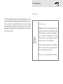
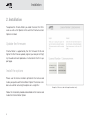
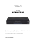
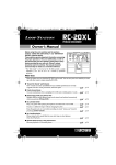
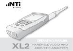
CINEMA METER
XL2
OPERATING MANUAL
HANDHELD AUDIO AND
ACOUSTIC ANALYZER
Contact NTi Audio at
Headquarter
Americas
China
Czech
Japan
South Korea
United Kingdom
+423 239 6060
[email protected]
+1 503 684 7050
[email protected]
+86 512 6802 0075
[email protected]
+420 2209 99992
[email protected]
+81 3 3634 6110
[email protected]
+82 2 6404 4978
[email protected]
+44 1438 870632
[email protected]
www.nti-audio.com
NTi Audio is an ISO 9001:2008
certified company.
Firmware V2.40
Version 2.40.02 / May 2015
All information subject to change without notice.
©
All rights reserved.
®
Minirator is a registered trademark of NTi Audio.
™
XL2, EXEL, M4260, M2211, M2215, M2230, MA220, MR-PRO, MR2 and TalkBox
are trademarks of NTi Audio.
Made in
Sw i t ze r l a n d
Table of Contents
Table of Contents
1. Introduction......................................................................4
2. Installation.......................................................................6
Update the firmware.......................................................6
Install the options ..........................................................6
Verify options installation................................................7
3. Getting Started................................................................8
4. Create a New Cinema......................................................9
5. Screen Overview............................................................12
6. Calibrating a Cinema Channel......................................14
Capturing a measurement............................................ 17
Calculating Average of captured traces ....................... 17
Storing a completed channel test................................. 18
Store . ....................................................................... 18
File overwrite............................................................ 19
Store and create verify test....................................... 19
Discard changes........................................................20
Show mean deviation................................................20
Back...........................................................................21
Multitone Headroom Test.............................................22
Preparing the headroom stimulus signals.................23
Loading a headroom test...........................................23
Conduct a Headroom Test.........................................24
7. Verify a Cinema...............................................................25
Lock into Verify Mode...................................................28
8. View verification results................................................29
9. EXIT.................................................................................31
Introduction
1. Introduction
Thank you for purchasing the Cinema Meter Package for the
XL2 Audio and Acoustic Analyzer. It is a functional extension for
all XL2 analyzers in the market, allowing you to efficiently commission and monitor the audio setup in commercial cinemas
following the SMPTE ST 202:2010 standard and the SMPTE RP
200:2012 recommended practice.
The Cinema Meter Package includes:
• Spectral Limits Option
• Cinema Assistant Option
Cinema Meter Package provides support for calibration according to the SMPTE ST 202:2010 standard as well as the SMPTE
RP 200:2012 recommended practice. It provides an efficient
workflow for setting up all screen channels, the surround channels as well as the LFE channel.
Each measurement project is designated to a “cinema” and
each cinema is separated into its own directory on the SD
card of the XL2. Assisted tasks select the target frequency
response (depending on the cinema size) and pre-define test
patterns for every individual cinema.
4
The cinema engineer then tunes the frequency response for
each channel and adjusts the absolute levels according to the
pre-defined tolerance patterns. Single measurements at a
“Golden Seat” as well as measurements averaged over various seat positions are supported.
Specific Meyer Sound headroom tests for all channels ensure
that maximum dynamic range is provided without clipping the
live audio material. These headroom tests are designed to be
executed on Meyer Sound cinemas only.
For each channel a response reading can be recorded at the
reference position which is then used as the comparable reference for all verification measurements.
Measurement verification is supported by an assisted mode,
allowing periodic measurement, documentation and verification of the response of each channel. Tolerance limits indicate
to the service technician whether tests have passed or failed
enabling him to notify the cinema engineer that the system
needs adjusting. For simplification, the verification mode can
be locked so that the XL2 analyzer boots with only that specific
measurement task activated.
Introduction
Warning
The cinema engineer can recall his calibration data at any time
and continue executing more detailed measurements for system verification or trouble-shooting of each channel. A designated viewer for verification measurements assists the cinema
engineer with comparing the verification data with the reference measurements.
Protect your ears
• Procedures in this manual require that synthesized test signals are played back through
the B chain of a cinema. These signals can
be very loud and exceed the normal levels
and can thus cause damage to speakers
and to your ears if used improperly.
• Check the volume control of your amplifier or
the level setting of the signal generator before unmuting the signal chain.
• Always wear hearing protection if in doubt.
5
Installation
2. Installation
To operate the Cinema Meter you need the latest XL2 firmware as well as the Spectral Limits and the Cinema Assistant
Options installed.
Update the firmware
Cinema Meter is supported by the XL2 firmware V2.40 and
higher. For the firmware update, register your analyzer at http://
my.nti-audio.com and proceed as instructed on the XL2 support page.
Install the options
Please use the license numbers printed on the license card
inside your purchased Cinema Meter Option. The license numbers are valid for activating the options on a single XL2.
Follow the installation procedure described on the license card
inside the Cinema Meter Option.
6
Example of a license card with sample numbers only.
Installation
Verify options installation
After installing the new firmware releases and the options, you
can visually verify the installation.
Select System Settings from the
main menu and press .
Use the page key
to bring the information screen into view.
The firmware version is displayed at
the top. The version must be 2.40 or
higher.
Both the Spectral Limits Option as well as the Cinema Assistant must be installed. Other options may be installed but are
not required to operate the Cinema Meter.
7
Getting Started
3. Getting Started
In order to understand the fundamental operation of the XL2
the user should be familiar with the XL2 Operating Manual,
available for download at www.nti-audio.com/XL2.
The fundamental steps of the Cinema Meter workflow are:
• Verify a cinema
This assisted mode guides the service technician through
the verification measurements to determine whether the
channel still performs to the tolerances defined earlier. Measurements are stored for later comparison. • Create a cinema
Assign name and other related parameters by executing the assistant Create new cinema. This creates a series of 8 tests; one for each speaker.
• Lock into verification
This mode locks the functionality into the verification mode after starting up the device and
simplifies the operation for verification users.
• Calibrate a cinema
Tune the frequency response and the absolute levels to
match the SMPTE tolerances. Measure at different seating locations and capture up to eight traces, at different
measurement positions, into the XL2 memory. Define the reference curve among your measurements and
let the assistant calculate the tolerance patterns for later verification measurements. • View verification results
The cinema engineer can review all the measurement data
obtained by the service technician to see when and how the
behavior of the channel has changed.
All these steps can be repeated for each channel in every cinema in any order.
You may recall previously-stored measurement sequences
at any later time. Both the test configuration and all captured
traces are stored. You may then continue adding new traces or
replace individual traces and store the complete test again.
8
Create a New Cinema
4. Create a New Cinema
In this chapter we create a new cinema. An individual folder for
each cinema is created on the file system of the XL2 within the
folder “Cinema”.
• The cinema parameter overview
opens. Here you can adjust the parameters for the selected cinema.
Each cinema folder then contains the test templates with tolerance calculation rules depending on the size of the cinema.
• Start the Cinema Meter by selecting the function Cinema Meter
from the main function menu list
and pressing
to launch it.
• A splash screen is displayed for 3
seconds or until you press .
• Select 1. Create new cinema from
the menu and press
to start the
process.
To name a new cinema, select Name with the rotary wheel
and press enter .
• Define the cinema name using
the rotary wheel and the keys as
indicated on the screen. Press
the OK key to confirm the name.
This brings you back to the cinema
parameter overview.
9
Create a New Cinema
• You may specify the number of
seats in the cinema by selecting
Size. The number of seats selected
determines which response pattern is used, as proposed in the
SMPTE ST 202:2010 standard.
• Select the number of seats in the
cinema. Cinema size of 500 seats
applies the standard X-curve while
other cinema size selections adjust
the X-curve as described in the table below.
Number of seats
10
Freq [Hz]
30
150
500
1000
1500
2000
2000
0dB
0dB
0dB
0dB
0dB
0dB
4000
1.0dB
0.5dB
0dB
-0.5dB
-1.0dB
-1.5dB
8000
2.0dB
1.0dB
0dB
-1.0dB
-2.0dB
-3.0dB
• Select the averaging time for the
frequency response measurements. Default is 60 seconds, giving a level accuracy of ±0.5dB at
the lowest frequency. With 30 seconds the lowest frequencies will
have an uncertainty of ±1dB.
• Select the averaging time for the
LFE channel. As the LFE handles
only low frequencies the default is
set to 120 seconds.
• You may now create the template
for that cinema by selecting -->
CREATE CINEMA and pressing
.
• The assistant then creates the
folder with the cinema name and
generates the appropriate tests in
that directory.
Create a New Cinema
Please note that all the cinemas are created in the root directory “Cinema” on the SD card. Possible pre-existing cinema
subdirectories are overwritten if you choose the same cinema
name and confirm the overwrite.
During the creation process numerous messages are displayed
informing you about the progress. After the successful creation
of the measurement template, the cinema meter assistant will
be back in the main menu, ready for the next tasks.
11
Screen Overview
5. Screen Overview
All the frequency response measurements are based on the
1/12 Oct + Tol measurement function. This function is automatically loaded when a cinema is calibrated or verified. All
required functionality is explained in this manual. There is
however more in-depth functionality explained in the XL2 user
manual. Here is a typical screen:
1
Result Symbols / Capture
Select this to capture measured traces, manipulate them
and handle tolerance files.
2
Tolerance file name / Shift level
Shows the actually selected tolerance file and the reference level for the tolerance. With this you may manually
shift the tolerance. The overall result and possible spectral
violations are shown below.
3
Y-Scale setting
Select the Y-Axis with the rotary wheel
and confirm with
enter .
Select the zoom factor between 2.5 and 20 and confirm
with enter .
Scroll up and down with the rotary wheel
to select the
Y-axis range.
Confirm with enter .
4
Spectral Measurement Result
Spectral results in 1/1, 1/3, 1/6 or 1/12 octave band resolution. Adjust the resolution at 12 .
5
Input Range
Access and display the physical input range of the Analyzer.
14 13
12
1
11
2
3
10
4
9
8
5
12
6
7
Screen Overview
6
Time Weighting
Offers selectable time weighting of 0.1, 0.2, 0.5 and 1.0
second.
7
Run Indication
The run indication shows the measurement status running,
paused or stopped. Various measurement settings are
locked during ongoing measurements, such as changing
the input range or the preset measurement time.
8
Actual Measurement Time
Shows remaining measurement time in hr:min:sec. The
setting is always set to single measurements. Start the
measurement by pressing the
key.
9
Preset Measurement Time
Adjustment of measurement time period for single timer
setting.
10
Broadband Results
User-selectable display of broadband results:
• A for A-weighted broadband sound pressure level
• C for C-weighted broadband sound pressure level
• Z for unweighted broadband sound pressure level
• - for no display
11
Readout Frequency
You may select any frequency to read out individual levels.
The selected frequency is indicated by the cursor arrow.
Choose between Automatic and Manual settings.
12
Setting of Test Result Resolution
Set the spectral result display to 1/1, 1/3, 1/6 or 1/12 octave
band resolution.
13
Phantom Power of Microphone
Phantom power / ASD Indication.
14
Measurement Result
Actual level result of the indicated frequency band. Select
the result of interest (EQ, live or any captured reading). The
actual level reading at the cursor arrow position is shown.
13
Calibrating a Channel
6. Calibrating a Cinema Channel
Once the cinema templates are created using the Create new
cinema assistant we are now ready to do the calibration measurements. During this process we will measure and verify the
frequency response, calibrate the absolute levels according
to the SMPTE requirements and conduct a headroom test to
verify sufficient dynamic range for every channel.
• Start the calibration process by
executing the 2. Calibrate cinema assistant in the Cinema Meter
mode.
• Select the cinema. The alphabetic
list of cinemas represents all cinemas that have been previously
created.
• Choose a speaker you intend to
calibrate. The complete test definition, including any previouslymade measurements, is loaded.
The test names comprise a test attribute (fRes), a sequential
number and the channel descriptor (e.g. BsL) as above.
Test Attribute
Test Description
fRes
Frequency Response measurements and
absolute C-weighted level adjustments (except for the LFE channel).
Hdrm
Head room tests
This is the level definition for the absolute levels defined in the
templates according to SMPTE ST 202:2010 and SMPTE RP
200:2012.
14
Calibrating a Channel
File name
Level C-WTD
Channel Description
L
85 dB
Left screen channel
C
85 dB
Center screen channel
R
85 dB
Right screen channel
Ls
82 dB
Left surround channel
Rs
82 dB
Right surround channel
BsL
82 dB
Back surround Left channel
BsR
82 dB
Back surround Right channel
LFE
--
Low Frequency Effects channel
The minimum and maximum tolerance limits for the selected speaker
are represented by the displayed
grey bar. Additionally the ideal curve
is plotted as a white line. The absolute levels of the tolerance limits are
set according to the SMPTE.
Start with a frequency response test. Select the speaker you
want to test and press .
15
Calibrating a Channel
This pre-defined configuration cannot be altered by measuring
additional curves. This means you may later delete all captured
traces and the arrangement remains still as pictured.
Place the instrument and the measurement microphone at the
first measurement position. This will most probably be the reference position or ideal seating position.
According to SMPTE ST 202:2010 and SMPTE RP 200:2012
the reference position is in the middle between L and R and
2/3 back in the room. Other seat positions for spatial averaging
may be added later.
It is highly recommended to place the microphone on a stand
and move a few meters away during the measurement, avoiding reflections from standing too close.
As the tolerance bands specified by SMPTE ST 202:2010 are
very small, we strongly recommend the use of a microphone
with a class 1 frequency response, such as the NTi Audio
M2211 or M2230 measurement microphone.
Use the -20 dBFS pink noise signal generator of your digital
cinema processor (DCP). Adjust the outputs of your cinema
processor to match the specified reference level for your theater for each channel.
16
Start a measurement with the START button
on the XL2
keyboard. The measurement is finished once the set time in
bottom right corner of the screen has elapsed. The result is the
level averaged (EQ) over the selected time period.
The bar on top of the graphical spectrum shows either PASSED
if all measurement points are within the tolerance limits, or
the violating measurement points are indicated with a small
vertical bar. The limit LED button of the XL2 reflects the overall
measurement result. It lights green if the test passed and red
if a tolerance limit violation occurred.
Calibrating a Channel
Capturing a measurement
Calculating Average of captured traces
Assuming the measurement is acceptable, we might want to
store this for later use or comparison. For this we use the Capture feature.
• Select the trace control icon
with the rotary wheel and
press enter .
For verification purposes and also for later steps we want now
to calculate and display the averaged response curve out of
individual readings.
• Select Capture EQ and press enter
to store this first reading.
You will be offered 8 possible storage locations. The default reading names are named after the
speaker name with consecutive
numbers but you are free to alter
them.
• A stored reading is then indicated by its time stamp. You can
overwrite the captured reading any time by storing a newer
reading in that location.
• Move the analyzer to another measurement position and
conduct the next measurement for the same speaker by
pressing
. Once the measurement time is elapsed you will
see the next measurement result on the screen.
• Capture this as well if desired until you are satisfied with the
number of measurement locations or until the capture buffer
is full.
• Select the reading selector with
the rotary wheel and press enter
.
• You see the reading selector
menu where you can select any
reading from the capture list. At
the bottom you can also select
Mean. But this memory is still
empty and we have to calculate it
first. We do this by selecting the
calculator item
next to Mean
using the rotary wheel and pressing enter .
17
Calibrating a Channel
• This opens the calculation selector
menu offering all captures for the
averaging process. Select those
you want to consider for the calculation by selecting the capture
with the rotary wheel and pressing enter . A considered capture
is indicated by a black dot.
• Scroll to Calculate Mean and press . This calculates the
Mean capture. You see now that the Mean reading has a time
stamp and can be used like any other capture. The Mean calculation process can be repeated at any time later.
• Leave the menu by pressing ESC.
Storing a completed channel test
• To continue the procedure once
you have completed the adjustments and measurements on that
specific channel, select >>Continue<< on the top left corner of the
measurement screen. You may
also reach this by pressing ESC.
• This opens a menu allowing you
to define the further use of your
acquired data.
Store
Select this entry to store all test definitions and the captured
data of a test including the last reading on the display.
18
Calibrating a Channel
• This saves the test under the
speaker channel number that you
are working with and asks you
whether you want to continue
with another channel.
• The assistant copies all the necessary settings from this test, applies the appropriate tolerances
and stores the last displayed reading as the reference curve for the
verification tests.
• Once the test is created you can
view the created Verify test. Press
OK to view the created test.
File overwrite
Please note that previously-stored results are
automatically overwritten.
Should you wish to keep older measurements
then we advise you first to create a new cinema
with a different name.
Store and create verify test
Stores the entire test as described before then creates the test
template for the verification mode and displays it for visual verification.
• Activate the test signal once more
and verify that the test is really
passing.
• Repeat the measurements if in
doubt or press >>Continue<< to
finish the process and continue
with another channel.
19
Calibrating a Channel
The intention of the verification procedure is to allow a service
technician to conduct guided measurements and confirm that
the performance of a speaker has not changed.
Please note that the reference curve used for the verification
procedure is the curve that was on the display immediately before executing this step. In case you want to record a distinct
measurement trace at the reference position then you should
do this just before you call this menu item.
Using the last trace on the display as the base for the reference
trace has the advantage that the advanced user can:
• Measure the reference curve at the reference position just
before the script is executed.
• Choose any of the captured traces for display (select best)
• Choose a number of captures to be averaged in MEAN (spatial averaging). Select then the MEAN for display before executing Store & create verify test.
You therefore have the choice to either conduct a measurement at the reference position or load any previously-captured
reading into the display.
20
Discard changes
Select this menu item in case you have no intention to store
the measured data. This can be the case if you have already
stored the data and did some more measurements for investigation purposes that are not required to store.
The acquired data is not saved to a file and thus all the captures
taken after the last Store will be lost.
• You will then be asked whether
you want to continue with other
channel measurements in the
same cinema.
• Yes brings you back to the channel selection while No brings you
back to the main menu.
Show mean deviation
Select this item to display the mean curve plus deviations of all
the previously-calculated readings.
Calibrating a Channel
Min/Max values are displayed as a
grey band and the mean values as a
solid white line. You may now select
the Result Symbols using the rotary
wheel and choose any of the captured traces to be displayed within
the Min/max limits.
Back
This menu entry brings you back to the measurement screen
with no changes and allows you to continue your measurement work in your current setup.
21
Headroom Test
Multitone Headroom Test
Damage warning
The headroom test allows the advanced sound engineer to
test the available headroom of the sound system before nonlinear effects appear.
The headroom test is an adjustment test only and is not available in the basic verification mode. With the wide band multi
tone test the screen channels are measured, while a dedicated low frequency test signal is used for the effects channel
(LFE).
The headroom test is a very stressful test that drives the system right to its limits. This test is intended for Meyer Sound
Cinemas only and shall only be conducted after a successful
level and frequency response calibration.
22
The headroom test excites the audio system
right to its limits beyond the standard levels.
This test is intended for Meyer Sound Cinemas
only and shall only be conducted after a successful level and frequency response calibration. Please be aware that this test may destroy
equipment if the tested components of your Bchain cannot handle the power!
Protect your ears
The headroom test applies sound pressures of
up to 105 dB SPL from multi tone signals. Such
levels can result in hearing loss and damage
your ears if not protected.
Before performing this test:
• Be sure others are clear of the area of high SPL
• Verify level settings first
• Always wear hearing protectors for this test.
Headroom Test
Preparing the headroom stimulus signals
Use the headroom test files from the Meyer Sound D-Cinema
Package or their Blue-Ray disk. Copy them to the Digital cinema processor (DCP), by following the standard procedure.
Contact Meyer Sound in case you need support in this matter.
Loading a headroom test
There are two headroom tests, one for the screen speakers
and a separate one for the LFE channel. Start any of these
two tests within the 2. Calibrate Cinema and choose HdrmScreen_FFT_ or Hdrm-LFE_FFT_ from your current Cinema
directory.
The FFT Analysis has been chosen and setup for its high resolution within these low frequencies. But since the XL2 screen
itself only can show 143 FFT lines per page, the full display
range has to be extended over multiple pages. The headroom
screen test data is therefore spread over two pages covering
the linear frequency range from 38 Hz up to 832 Hz, while the
headroom LFE test requires a total of four FFT pages ranging
from 10 Hz up to 200 Hz. The page key
steps sequentially
through all these pages. To get the full view of the FFT pages you
have to align them sequentially. The screens have sufficient overlap so that no spectral content is lost.
The test definition automatically activates the FFT function
module with pre-selected screen views.
The screen channel headroom test appears as follows:
The multi tone tests expect certain
signal components to be present
and others must not be higher than
certain levels (75dB in the example
to the left).
You may observe that the right-most signal bin on the left
screen is again visible on the left of the right-hand screen.
23
Headroom Test
The LFE headroom test appears as follows:
The four pages again overlap sufficiently so that we can monitor
if harmonic or intermodulation frequencies appear anywhere in
the spectrum due to clipping of the amplifiers.
The tolerance patterns matches the multi tone signal that
must be played through the speaker under test. The test signals are available for download at the NTi Audio user website
http://my.nti-audio.com. You may store these files on the MRPRO Signal Generator for convenient and portable playback
Conduct a Headroom Test
Run the appropriate headroom test signal from the cinema processor library and start the FFT measurement by pressing play
. If the system operates in its linear range, then the amount
of harmonic and intermodulation distortion remains under the
spectral limits.
To playback and level the signal, follow your internal procedures.
24
• With a signal exceeding the linear
range the harmonics will exceed
the tolerance limits and the test
indicates “Fail”.
• In the example, the black lines
on top of the spectrum display
indicate tolerance limit violations
throughout the entire spectrum.
Verify a cinema
7. Verify a Cinema
The cinema verification mode allows a service technician to
periodically conduct maintenance measurements within a cinema, following instructions displayed on the XL2 screen.
The intention of these measurements is to find out whether
the speaker performance at the reference location is still as
originally defined and documented by the cinema engineer
who calibrated the cinema.
The operator sees the measurement results and the pass/fail
result. He can repeat a failed test but he is not able to alter the
tolerance limits.
• Start the verification assistant by
selecting 3. Verify cinema.
• Select the cinema.
• The available cinemas have been
previously created by the cinema
engineer and are presented in alphabetic order. Confirm your selection with enter .
In case of continuous fails of certain tests the service technician can then notify the cinema engineer who has access to
the measurement history of that speaker.
The service technician is not necessarily a measurement expert, as he has only to follow the clear instructions given on
the screen.
25
Verify a cinema
• You are now requested to place
the measurement microphone
at the reference position. The
microphone position remains unchanged for all the channels verified in this process.
• Adjust the height of the microphone according to the specification of the cinema engineer.
• Continue with enter .
• Select the channel you want to
verify. Please note that the only
channels available for the verification are those that have been
previously commissioned by the
cinema engineer.
• Confirm with enter .
• Use the -20dBFS pink noise signal
of your cinema processor (DCP),
on the channel you have selected
to verify.
• Press enter
to confirm once
the noise signal is playing.
26
• Make sure that you have no interfering noises present in the
theatre (no talking and keep the
doors shut).
• Start the measurement by pressing enter .
• The measurement starts immediately and you see the total time
as well as the remaining measurement time in the bottom right corner.
• The measurement result is displayed after the measurement period has elapsed.
• At this point you may use the rotary wheel to select either
the readout frequency field (400Hz in the above example) or
the Y-Axis where you can zoom and scroll the levels. Please
note that these viewing scroll actions do not influence the
measurement result at all; they are just altering the scaling.
• Once you are done with the adjustments, select >>Continue<< with the rotary wheel and press enter .
Verify a cinema
• In case the measurement did not
pass the stored tolerance limits
you will be notified with the limit
LED lighting up red and with a
“Failed” message.
• You can now select whether you
want to repeat that measurement.
• Choosing Yes discards the current measurement and allows
you to repeat this measurement step. A No selection brings
this (failed) test forward.
• Confirm your selection with enter .
• In the next step you may now
compare the measurement results just acquired with either previous measurements or the stored
reference. No skips this step.
• Confirm your selection with enter
.
• In case you choose Yes, you can
now select the capture you want
to compare your last measurement against. The selection can
be any earlier stored capture (L1
to L8) or the reference trace. Note
that the reference trace cannot be
altered in the verification mode.
• Confirm your selection with enter
.
• You now see a relative display of
your measurement result minus
the selected reference capture.
With no deviations you would see
a straight line centered on 0dB.
• Using the rotary wheel, you may
now select the readout frequency
field (40.00Hz in this example) or
the Y-Axis where you can zoom
and scroll the levels.
• Once you are done with the comparison, select >>Continue<< with the rotary wheel and press enter .
27
Lock into Verify Mode
• You are asked whether you want
to do comparisons against other
readings. Do so by selecting Yes
or select No to continue with the
next step in the script.
• Confirm your selection with enter
.
• You may store the measurement
results or discard them. In case
you select Yes then the measured
reading is stored in the next free
location L1 to L8. If all eight capture memories are occupied then
the oldest capture is automatically
overwritten.
• This mechanism ensures that you and the cinema engineer
always have access to the history of the last eight measurements. They are all complete with date and time stamps.
• Confirm your selection with enter .
• This step completes the measurements for a specific channel. In the next screen you will be asked if you want to continue doing measurements in the same cinema but with another channel.
28
Yes brings you back to the channel
selection menu and No finishes the
Verification mode and brings you
back to the main menu. Confirm
your selection with enter .
Lock into Verify Mode
If you select this menu item you are configuring the XL2 to
always boot-up in the verification mode. This has the strong
advantage that the occasional user can easily get to the verification mode.
• Select 4. Lock into verify mode.
View verification results
• A confirmation screen appears.
Select OK to activate this locked
mode or Cancel to return to the
Cinema Meter menu.
8. View verification results
The service technician has verified the cinema channels at various dates. This viewer allows you to look at this data and compare it against other readings.
• Select 5. View verification results to enter the viewer mode.
• In this mode the XL2 analyzer always boots up in the locked verification mode.
• Exit the locked mode at any time
by selecting Unlock in the bottom
left corner.
• Select the cinema.
29
View verification results
• The list represents all channels
containing verification results.
• Select a channel.
• Select a first measurement result
you want to visualize. The presented captures show the history
of verifications of that channel.
Each capture is marked with a
time stamp.
• The last capture in the list is the
reference trace.
• The measurement result is then
visualized together with the applicable tolerance band and possible violations. Also the limit LED
shows the overall status of that
measurement.
30
You can zoom and scroll the Y-scale of the graph for optimizing the visibility of details. Select >>Continue<< in the top left
corner once you are ready to continue.
• You are then asked whether you
want to compare the previouslyselected measurement result
against another capture.
• This can be, for example, the reference curve to see the deviation
to the original measurement or
any other earlier capture for monitoring changes over time.
• Select a capture from the list.
Exit
• The screen shows you the differences between these two measurements across the frequency
spectrum as well as the broadband value difference.
• You are again free to adjust the
readout frequency field and the YAxis scaling of the graph for best
readability.
9. EXIT
• Selecting 6. Exit terminates the
Cinema Meter mode and return to
normal XL2 operation.
• You can restart the Cinema Meter at any later time via the main
menu.
• After having completed the views
on a selected channel you may do
the same with another channel
in the same cinema or exit to the
Cinema Meter menu.
31