1
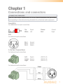
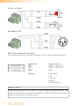
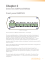
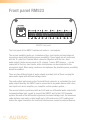
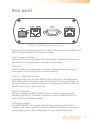
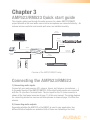
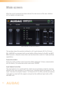
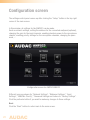
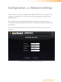
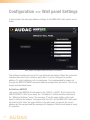
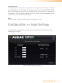
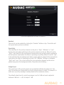
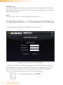
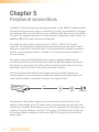
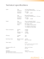
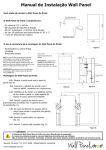
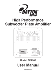
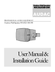
AMP523/RM523
User Manual
www.audac.eu
2
Index
Introduction
5
Precautions
7
Chapter 1: Connections and connectors 9
9
Safety requirements
Caution servicing
EC Declaration of Conformity
Waste of Electrical and Electronic Equipment (WEEE)
Connection standards
7
7
7
8
Chapter 2: Overview AMP523/RM523
11
Chapter 3: AMP523/RM523 Quick start guide
15
Chapter 4: User interface & configuration
17
Chapter 5: Peripheral connections
28
Chapter6: Additional information
29
Front panel AMP523
Front panel RM523
Rear panel AMP523/RM523
Block Diagram
Connecting the AMP523
Configuring the AMP523
Login screen
Main screen
Configuration screen
Network settings
Wall panel settings
Input settings
Priority settings
Password settings
Factory settings
IP Basics
Technical specifications
11
12
13
14
15
16
17
18
20
21
22
23
24
26
27
29
31
3
4
Introduction
Web Based Mini Stereo Power Amp
The RM523 and AMP523 are web based input control units, allowing the connection and
control of several stereo audio source devices (such as CD-player, Tuner, MP3 player,
... ) and a microphone.
They both have 4 Stereo Line Inputs, 1 Stereo Line output and 1 Balanced Microphone
Input with Phantom Power performed together on a 18-pins terminal block connector.
A line level output has been provided as alternative output, to link the output signal to
external devices such as recorders or amplifiers.
The RM523 has an output performed with an RJ45 connector. This output is a differential audio output with increased voltage level, meant to connect the RM523 unit
to the LX523 active speaker system. Because of the differential signal and increased
voltage level, the maximum cable distance can reach a cable length up to 500 meters
over CAT5 cabling and makes the signal insensitive for noise and interference caused
by external devices.
The AMP523 has an amplified stereo speaker output with a power of 2 x 15 W power.
The amplifier construction is based on Class-D technology ensuring a high efficiency
and reliability.
The input switching, volume regulation and other functions control can be done in several ways. Using a web-browser it can be controlled from any computer in the same
network as the AMP523 or RM523. An RS232 and RS485 control port allows the integration and control of the device in any home or industrial automation system and
tablets or smartphones can be used to control functionality by using one of the specially
developped Apps.
To make the installation even more complete, an optional MWX43 or MWX45 wall panel
can be installed to control the signal routing and volume level from one or multiple fixed
locations.
5
Precautions
READ FOLLOWING INSTRUCTIONS FOR YOUR OWN SAFETY
6
•
ALWAYS KEEP THESE INSTRUCTIONS FOR FUTURE REFERENCE. NEVER
THROW THEM AWAY
•
ALWAYS HANDLE THIS UNIT WITH CARE
•
CLEAN ONLY WITH DRY CLOTH
•
HEED ALL WARNINGS AND FOLLOW ALL INSTRUCTIONS
•
NEVER EXPOSE THIS EQUIPMENT TO RAIN, MOISTURE, ANY DRIPPING OR
SPLASHING LIQUID. NEVER PLACE AN OBJECT FILLED WITH LIQUID ON TOP
OF THIS DEVICE
•
DO NOT INSTALL THIS UNIT NEAR ANY HEAT SOURCES SUCH AS RADIATORS
OR OTHER APPARATUS THAT PRODUCE HEAT
•
DO NOT PLACE THIS UNIT IN ENVIRONMENTS WITH A HIGH LEVEL OF DUST,
HEAT, MOISTURE OR VIBRATION
•
THIS UNIT IS DEVELOPED FOR INDOOR USE ONLY. DO NOT USE IT OUTDOORS
•
PLACE THE UNIT ON A STABLE BASE OR MOUNT IT IN A STABLE RACK
•
ONLY USE ATTACHMENTS & ACCESSORIES SPECIFIED BY THE
MANUFACTURER.
•
UNPLUG THIS APPARATUS DURING LIGHTNING STORMS OR WHEN UNUSED
FOR LONG PERIODS OF TIME
•
CAREFULLY CHECK THE UNIT’S CONDITION AFTER UNPACKING.
IF THERE IS ANY DAMAGE TO THE CARTON BOX OR THE UNIT ITSELF,
INFORM YOUR VENDOR IMMEDIATELY.
•
ONLY CONNECT THIS UNIT TO A MAINS SOCKET OUTLET WITH PROTECTIVE
EARTHING CONNECTION
•
THE INSTALLATION, CONNECTION AND CONFIGURATION OF THE DEVICE
SHOULD BE DONE BY QUALIFIED TECHNICIANS
CAUTION
•
USE CABLES OF THE RIGHT GAUGE FOR CONNECTING LOUDSPEAKERS ON
THE AMPLIFIED OUTPUTS
•
USE CABLES WITH CLEAR COLOUR CODING INDICATING THE POLARITY AND
MAINTAIN THE SAME POLARITY THROUGHOUT THE WHOLE SYSTEM.
•
ONLY USE THE CORRECT LOAD IMPEDANCE (MIN 4 OHM) WHEN
CONNECTING LOUDSPEAKERS ON THE AMPLIFIED OUTPUTS. EXCEEDING
THESE LIMITS COULD CAUSE FIRE OR OTHER FAILURES.
•
DO NOT CONNECT INDUCTIVE LOADS DIRECTLY TO THE AMPLIFIED OUTPUTS
•
AVOID ELECTRIC SHOCKS: SWITCH OFF THE AMPLIFIER WHEN CONNECTING
CAUTION - SERVICING
This product contains no user serviceable parts. Refer all servicing
to qualified service personnel. Do not perform any servicing
(unless you are qualified to do so.)
EC DECLARATION OF CONFORMITY
This product conforms to all the essential requirements and
further relevant specifications described in following directives: 2004/108/EC (EMC) and 2006/95/EC (LVD)
WASTE ELECTRICAL AND ELECTRONIC EQUIPMENT (WEEE)
The WEEE marking indicates that this product should not be
disposed with regular household waste at the end of its product
life. This regulation is created to protect both the environment
and human health.
This product is developed and manufactured with high quality
materials and components which can be recycled and/or reused.
Please dispose of this product at your local collection point or
recycling centre for electrical and electronic waste. Do this to
make sure that the product is recycled in an environmental friendly
way, and help to protect the environment in which we all live.
7
8
Chapter 1
Connections and connectors
CONNECTION STANDARDS
The in- and output connections for AUDAC audio equipment are performed
corresponding to international wiring standards for professional audio equipment.
Cinch (RCA):
For unbalanced line input connections
Tip:
Signal
White: Left
Sleeve: Red: Left:
Signal - Center: Signal + Right: Ground (XLR Pin 3)
(XLR Pin 2)
(XLR Pin 1)
Ground
Right
XLR:
For balanced input connections
Pin 1: Ground
Pin 2: Signal +
Pin 3: Signal -
3-Pin Euro-Terminal Block:
For balanced input connections
For balanced input connections:
9
Line in- or output
Microphone input
RS232 (serial connection interface):
For connection with home automation systems, or other remote control equipment
Connection
PIN 2
PIN 3
PIN 5
Standard RS232
RM523 / AMP523 TX
RM523 / AMP523 RX
GND
Settings
19200 Baud
8 Bit
1 Stop bit
No parity
No Handshaking
RS232 & TCP/IP
The AMP523 & RM523’s RS232 and TCP/IP ports accept the same commands. The
complete command set is available in the AMP523 / RM523 commands user manual
which is freely available on www.audac.eu
10
Chapter 2
Overview AMP523/RM523
Front panel AMP523
AMP523 Front panel
The front panel of the AMP523 contains audio in- and outputs.
The various available inputs are 4 unbalanced line-level inputs and one balanced
microphone input (with phantom power possibility). Those inputs are all performed
with an 18-pins Euro Terminal block connector (together with the line-level
audio output). Audio sources such as CD-players, Tuners, MP3 players, ... can be
connected to the line-level inputs, while microphones can be connected to the
microphone input. When using condenser microphones, the phantom power possibility
should be enabled.
There are two different kinds of audio outputs provided, both of them carrying the same
audio signal with different levels.
The audio output performed on utmost left side of the 18-pin Terminal Block
connector is a standard line level output whereby the AMP523 can be connected to
any audio device with a line-level input such as an amplifier, pre-amplifier, active
speaker system, ...
The second audio output marked as ‘AMP OUT’ is the output of the internal Class
D amplifier with an output power of 2 x 15 Watt which can be used for powering
loudspeakers.
11
Front panel RM523
RM523 Front panel
The front panel of the RM523 contains all audio in- and outputs.
The various available inputs are 4 unbalanced line-level inputs and one balanced
microphone input (with phantom power possibility). Those inputs are all performed
with an 18-pins Euro Terminal block connector (together with the line-level
audio output). Audio sources such as CD-players, Tuners, MP3 players, ... can be
connected to the line-level inputs, while microphones can be connected to the
microphone input. When using condenser microphones, the phantom power possibility
should be enabled.
There are two different kinds of audio outputs provided, both of them carrying the
same audio signal with different voltage levels.
The audio output performed on the Terminal Block connector is a standard line level
audio output whereby the RM523 can be connected to any audio device with a linelevel input such as an amplifier, pre-amplifier, active speaker system, ...
The second output is performed with an RJ45 and is a differential audio output with
increased voltage level, meant to connect the RM523 unit to the LX523 speaker
system. Because of the differential signal and increased voltage level, the maximum
cable distance can reach a cable length up to 500 meters over CAT5 cabling and
makes the signal insensitive for noise and interferrence caused by external devices.
12
Rear panel
AMP523 and RM523 have the same rear panel
All the control and configuration ports are located on the rear panel of the AMP523 and
RM523, together with the 24 Volts power connection.
1) 24 Volts power connector:
The included 24 volts power supply (PSD241) should be connected to this connector.
Pay attention to the polarity when connecting the power supply.
2) Run LED:
This LED shows the operation mode of the device. When the device is running in
normal mode, this LED will blink at a constant frequency.
3) RS485 + Audio RJ45 connector:
An additional Wall Panel Controller (MWX43/45) and Wall Line or Wall Microphone
input (WMI and WLI units) can be connected to this input. This way, the volume and
the signal routing can be adjusted by means of a wall panel and additional local Line
and Microphone inputs can be connected.
4) RS232 control port:
With this connector, the AMP523/RM523 can be connected to external control
hardware using RS232. This makes it possible to control the AMP523/RM523 by
means of an home automation system.
5) Ethernet connection:
The AMP523/RM523 can be connected to an Ethernet network with this RJ45
connector. This makes it possible to control the AMP523 functions over ethernet, by
simply using any device with a web browser such as computer, smartphone, ...
13
Block Diagram
14
Chapter 3
AMP523/RM523 Quick start guide
This chapter guides you through the setup process for a basic AMP523/RM523
project whereto a line level audio source and a microphone are connected directly . An
external volume controller and remote wall mixer are installed remotely.
stereo
line input
cd player
stereo
line input
computer
1 2
3 4
5
6
stereo
line input
mp3 player
tuner
.........
TCP/IP
ok
home
automation
system
balanced
mic input
RS232
2 x 15 W
stereo
line output
Overview of the AMP523/RM523 setup
Connecting the AMP523/RM523
1) Connecting audio inputs
Connect all your audio sources (CD-players, tuners, mp3 players, microphones, ... )
to the audio inputs of the AMP523/RM523. All the direct audio inputs are connected
with the 18-pins Euro Terminal block. The pin layout for the 18-pins connector is
shown at the front panel overview at page 11 of this user manual. The wiring diagram
for connecting stereo line sources and microphones is shown at page 10 of this user
manual.
2) Connecting audio outputs
Depending whether the AMP523 or the RM523 is used in your application, two
different kinds of outputs are available. Both of them are containing a line level
15
output which is performed on the 18-pin terminal block connector while a separate
output is provided for the loudspeakers output. For the RM523 this output is meant
for connecing an active loudspeaker system and performed with an RJ45 connector.
For the AMP523 the internal amplifier output is performed using a separate 4-pin
Terminal block connector whereto passive loudspeakers may be connected.
3) Connecting the power supply
The included power supply should be connected to the 2-pins Euro Terminal block
connector. Watch the polarity when connecting the power supply.
4) Connecting a computer
A computer can be connected to the AMP523/RM523 via ethernet connection. This is
connection is made by a CAT5 cable. (Use the RJ45 connector which is marked with
‘Ethernet’) If the computer is directly connected to the AMP523/RM523, a crossed
network cable is necessary. If the AMP523/RM523 is connected to a local LAN
network (connected to a router / switch / hub) a straight network cable is necessary.
Ask your IT administrator for help. To get access to the user interface, enter the
following address in your internet browser address bar: “http://192.168.0.193” (This is
the factory default IP address of the AMP523/RM523 and can be changed in the user
interface). The default password for the AMP523 is: ‘AMP523’ and for the RM523 is:
‘RM523’.
Configuring the AMP523/RM523
1) Changing the IP address
You can skip this step when the default IP address “192.168.0.193” is not used by
another device in your network, and is OK for you. If you like to change the IP address,
go to the “Setup” menu (click the icon in the upper right corner of the main screen)
and click “Network Settings”. Now you can change the IP address, and click “OK” to
apply the changes and save. Afterwards, your browser will be automatically redirected
to the new IP address of the AMP523/RM523, and the default IP address is not longer
valid.
2) Changing the password
You can skip this step if the default password is OK for you, buy we always
recommend to change the password, especially when your device is connected
to a public network which external users have access to. If you like to change the
password, go to the “Setup” menu and click “Password settings”. Here you can
change the password. First, the old password needs to be entered, and subsequently
the new password needs to be entered twice (Max 10 characters). Press the “OK”
button to save the new password. Now, you always need to log in with the new
password and the default password is no longer valid.
16
Chapter 4
User interface & configuration
To get access to the control and configuration settings, the AMP523/RM523 should
be connected to a computer or en Ethernet LAN network. For more information about
network connections and settings, see IP basics in chapter 6.
The standard (factory default) IP address of the AMP523/RM523 is 192.168.0.193,
make sure this address is within the IP range of the connected Ethernet LAN network
(subnetmask 255.255.255.0). If the default network address is not within range of your
LAN network, contact your network specialist. The network address can be changed
with the Standard Web Based User Interface but therefore a network connection must
be made first!
Any device (PC, Laptop, PDA or even a Smartphone) with a web browser and the
Macromedia Flash 8.0 plug-in (or higher) installed, can be used to control the web
based user interface.
For mobile devices, such as PDA’s, smartphones or even iPhones or iPads, special
applications are developed to control the standard functions of the AMP523/RM523.
User interface & configuration
Start your default web browser and enter the IP address of the embedded web
server of the AMP523/RM523 in the address bar. (The factory default IP address is
http://192.168.0.193)
Login screen
First the login screen will be displayed.
A password should be entered to get access to the web interface. After the correct
password is entered, click the “OK” button, and you will be redirected to the main
screen of the AMP523/RM523. (The factory default password for the AMP523 is
‘AMP523’ and for the RM523 is ‘RM523’.
NOTE
The passwords can be changed in the Configuration >> Password settings menu
17
Main screen
After the correct password has been entered, the main screen of the user interface
will be loaded as shown below.
Main screen for AMP523/RM523
This window shows the selection buttons for all 5 input channels (CH1 to CH4 and
WLI-WMI/MIC) accompanied with a mute button, Mixing faders for the WLI and MIC/
WMI Channels, a General volume fader and two band tone control for Treble and Bass
equalization. Connection status
At the top centre position is the Connection Status displayed. To have communication
with the device, the connection status must show ‘ONLINE’.
Input channel selection
The input channel to be routed with the output can be selected by using the selection
buttons in the centre position of the main screen. Selection buttons are shown for “No
input”, the direct line inputs Channel 1 to Channel 4 (CH1 to CH4), and the microphone
input which is mixed with the signals coming from the additional input units as WLI
and WMI units.
18
Mute button
Below the input channel selection buttons is a big MUTE button provided, by clicking
this button the output signal will be completely supressed. When the signal is muted
this button will turn Red. The output can be unmuted after clicking this button again.
Volume Control
The output volume can be set by moving the master fader up and down. The master
fader is indicated with “Output” located on the right side next to the input selection
buttons. At the top and bottom side is a button with an arrow displayed whereby the
volume can be raised and lowered in steps of 1 dB.
Mixing faders for WLI and MIC/WMI
On the left side of the main screen there are two mixing faders displayed. With these
faders, the signals coming from the additional wall panel inputs can be mixed with
each other. The mixing with WLI and MIC/WMI channels is 50% and the level can
be adjusted with both faders between 0 dB and -∞ dB. This can be easily done by
sliding the faders up and down or by pressing the arrowed buttons on top and bottom
of the faders. This way the level can be raised and lowered in steps of 1 dB.
Two band tone control
On the right side of the main screen there are two faders displayed which are meant
to adjust the sound settings through two-band tone control. The leftmost fader
indicated with “Bass” offers the possibility to adjust the level of the low frequencies,
while the rightmost fader indicated with “Treble” offers the possibility to adjust the
level of the high frequencies. The sound level level for both low and high tones can
amplified or attenuated between +14 dB and -14 dB.
Configuration menu
In the top right corner is a “Setup” button displayed. After clicking this button, you will
be redirected to the general configuration menu of the AMP523/RM523.
Save
Press the “Save” button in the top right corner when any changes are made to
the settings on the main screen. Otherwise all settings will be set to default after
reloading the web-based interface.
19
Configuration screen
The settings control panel comes up after clicking the “Setup” button in the top right
corner of the main screen.
In this window, all settings for the AMP523 can be made. Such as network settings, setting the address for the connected wallpanel (optional),
changing the gain for the input channels, enabling phantom power to the microphone
channel, enabling priority settings for the microphone channels, changing the password, ...
Configuration screen for AMP523/RM523
Different icons are shown for “Network Settings”, “Wallpanel Settings”, “Input
Settings”, “WMI/Mic Priority”, “Password Settings and restore to “Factory Settings”.
Click the particular button if you want to make any changes to those settings.
Back
Click the “Back” button to return back to the main screen.
20
Configuration >> Network Settings
In this window, the network settings of the AMP523/RM523 can be adjusted. The
IP address is default set to 192.168.0.193 and the subnetmask is default set to
255.255.255.0.
The settings can be changed by adjusting the parameters in the shown fields. To confirm the settings, press the OK button. The changed settings will take effect
immediately.
For more information about network connections and settings, see IP basics in
Chapter 6.
Network settings screen for AMP523/RM523
21
Configuration >> Wall panel Settings
In this window, the wall panel address settings for the MWX43/45 wall panels can be
made.
Wall panel settings screen for AMP523/RM523
The address is always set correct for new delivered wall panels. When the connected
wallpanel has been used in another application, it can be configured to another
address. To avoid problems in all circumstances, it is recommended to always run
through the AMP523/RM523 wall panel address configuration procedure. This is very
simple and described below.
Set Address AMP523
Just connect the MWX43/45 wall panel to the “RS485 + AUDIO” RJ45 input on the
AMP523/RM523. After this is done, the “Set Address” button should be pressed in
the “Wallpanel Settings” menu. The message “Push the upper button on the wall
panel to confirm the address” will appear and the LED’s on the MWX43/45 wall panel
will start to blink. After the upper button on the wall panel is pressed, the correct
address will be assigned and the message will disappear. Now the wall panel is ready
for operation.
22
Input selection
The wallpanel can be used to change which input is routed to the output. The default
is all channels are selected. Now if you only use channels 1 to 3 and the WLI-WMI/
MIC channel then you can select the off option in the “input selection” dropdown list
of channel 4. This will disable channel 4 from the routing list of the wallpanel so you
can’t route the unused input to the output.
Back
Click the “Back” button to return back to the settings screen.
Configuration >> Input Settings
In this window, input settings such as input gain adjustment and phantom power
enabling can be made.
Input/Output for AMP523/RM523
23
Input gain
On the left side all input channels are shown, together with a dropdown list. With
this list the input gain for every channel can be adjusted. The default input gain for
every channel is set to 0 dB. It can be set between -4 dB and +10 dB, in steps of 2
dB. This can simply be done by clicking the dropdown list and selecting the desired
gain adjustment factor. When the desired value is selected the changes will take
immediate effect.
Phantom power
A button to enable Phantom Power for the microphone channel can be found on the
right side. This can simply be done by clicking this button. When the phantom power
is enabled, this button will turn green and 15 Volts phantom power will be delivered to
the microphone input. (Only direct mic input and not WMI)
Output mono
A button to enable Mono output can be found on the right bottom side. When not
enabled the output will be in stereo.
Back
Click the “Back” button to return back to the settings screen.
Configuration >> Priority Settings
In this window you can make priority settings such as sensitivity and level adjustment
for the microphone inputs. When applying a signal to the microphone input (when
someone is talking in the microphone), all other signal sources will be suppressed.
24
Priority settings screen for AMP523/RM523
Enabled
The priority can be enabled by clicking the “Enabled” button on top. This button will
turn green when priority is enabled. Sensitivity
The sensitivity for the priority channel can be put on “High”, “Medium” or “Low”.
Hereby, the level when switching to the priority channel can be set. When it’s set to
“High”, it will switch to the microphone channel when only a small signal is applied to
the microphone input (when the talker is speaking very softly). When it’s set to “Low”,
it will switch to the microphone input when a large signal is applied to the microphone
input (when the talker is speaking very loud). The “Medium” setting is in between
“High” and “Low”. The correct setting for your application depends on the microphone being used, the background noise, the person who’s talking, ...
Output Level
The sound level of the priority signal can be adjusted with this dropdown list. This
way, the volume can change when a priority announcement is made. For example, to
make sure a priority message is always heard at the maximum volume, ...
The default output level for priority messages is set to 0 dB and can be adjusted
between 0 dB and -∞ dB, in steps of 1 dB.
25
WMI/MIC Level
The level of the priority input can be set by means of this dropdown list. The correct
level depends of the used microphone, and should be set correctly so the microphone
signal is not overdriven.
Back
Click the “Back” button to return back to the settings screen.
Configuration >> Password Settings
In this window the password for the AMP523 can be changed.
Password settings screen for AMP523/RM523
To change the password, enter the old password in the provided field and enter the
new password twice in the provided fields. After this is all completed, push the “OK
button. If the old password is correct, and the new password filled in both fields
match, the old password will be changed into the new password.
The factory default password is “AMP523”.
26
Configuration >> Factory Settings
BE CAREFULL to press this button. It really will recall the ORIGINAL factory settings !!!
It does not recall the previously saved settings, but it recalls the original factory setting
and the previously made settings will be lost.
Click the “OK” button to reset the settings to factory default.
Factory settings screen for AMP523/RM523
27
Chapter 5
Peripheral connections
In addition to the direct line and microphone inputs on the AMP523, additional wall
line and microphone inputs can be connected. It provides the possibility to connect
one additional Wall Line Input (WLI) and one additional Wall Microphone Input (WMI).
To control the standard functions like input selection and general volume control, an
additional MWX43/45 wall panel can be connected.
The additional units must be connected to the “RS485 + AUDIO” RJ45 input
connector. The data transfer between both audio input units and the control units is
done over a single CAT5 (or better) cable. The wiring should be straight, according to
the wire colour coding as shown in “Chapter 1: Pin connections and connectors” of
this user manual.
The signal coming from the Wall Microphone Input is combined with the direct
microphone input and priority settings also affect the Wall Microphone input signal.
Both inputs are mixed with each other and the volume for each channel can be set
separately by using the fader on the web-based user interface.
The wiring between the different units simply needs to be linked-through. An
example diagram of how the system including the additional wall audio inputs and
control panel should be connected is shown in the diagram below.
Cat5
+
Prog.
-
+
Vol
-
AMP523
WLI
WMI
MWX43/45
The maximum cable distance depends on the amount of connected units on the
databus. Cable lengths up to 300 meters can be achieved when only one input unit
needs to be connected. When two (or more) units are connected, the maximum cable
length for the entire databus is limited to 150 meters. The maximum bus length can
be increased when an additional junction box (ARJ03P) is placed with an external
power supply.
28
Chapter 6
Additional information
IP Basics
Many AUDAC products are controllable by Ethernet. The Ethernet connection which
is used on the AUDAC products is TCP/IP based like 99% of the computer networks.
There are some basics which you need to know to successfully make a TCP/IP Ethernet
connection.
The data in TCP/IP networks is always send in packages, all these packages must be
delivered to a unique address, just like the mailman delivers mail to your home mailbox.
In TCP/IP networks, this address is called the “IP address”. The IP address is always a
number in the following format “192.168.000.001”. As you can see, this address consists
of 4 separate numbers ranging from “000” to “255”.
In simple terms, only the last number of an IP address can be different within a
network, so there is a maximum of 256 unique addresses within a network, ranging
from “xxx.xxx.xxx.000” to “xxx.xxx.xxx.255”. The first three numbers have to be
the same to make communication between several devices possible, otherwise the
devices can not communicate with each other.
Example:
Device 1:
IP address:
192.168.000.001
Device 2:
IP address:
192.168.000.002
Device 3:
IP address:
192.168.001.003
In this example, Device 1 can communicate with Device 2, but not with Device
3, because the first three numbers have to be the same. These first three parts
are called the “IP range”, so the devices have to be in the same “IP range” to
communicate with each other.
29
The “IP ranges” of home and office networks are defined by the network
administrator, this means that the IP range of your home or office network can
be different from another network. AUDAC products have the following default IP
address: “192.168.0.xxx”, this means the standard IP range of AUDAC products is
“192.168.000.xxx”. If your network is using a different IP range, the AUDAC products
will not be accessible from your network. You can change the IP address of the
AUDAC products to make them work properly in your network. This can be done in
the settings menu, and is described extensively in the “Settings” chapter of this user
manual.
Of course, to make changes to the settings menu of the AUDAC products, you need
to have access to the user interface on the product’s webpage. This can be done by
temporarily giving your computer an IP address within the IP range of the AUDAC
product, for example “192.168.0.193”. After the IP address of your computer is within
the IP range of the product, the user interface is accessible and the IP address of the
product can be changed to an IP address within the IP range of your network. If the
IP address of the product is within the IP range of your network, you can change the
IP address of your computer to it’s former IP address and the product should work
properly in your home or office network.
Ask your network administrator for help if you are not familiar with networks.
Summary
- All devices must have a unique IP address
- All devices must be within the same IP range
30
Technical specifications
Inputs
Type
Connectors
Impedance
Sensitivity
4 x Stereo Balanced Line
18-pin Euro Terminal Block - 3.81 mm
20 k Ohm
- 10 dBV ~ +4 dBV
Type
Connectors
Impedance
Sensitivity
Balanced Microphone
3-pins Euro Terminal Block ~ 3.81 mm
47 k Ohm
- 34 dBV ~ -18 dBV
Output
Type
Connectors
Impedance
Power Stereo Loudspeaker Output
4-pins Euro Terminal Block ~ 5.08 mm
Min Load of 4 Ohm
2 x 7.5 Watt @ 8 Ohm Stereo
2 x 15 Watt @ 4 Ohm Stereo
1 x 30 Watt @ 8 Ohm Bridge
Power consumption
Standby Idle
Nominal (1/8 MUP)
1/8 MUP 2.6 Watt
3.7 Watt 7.1 Watt
36.8 Watt
Efficiency
1/8 MUP MUP
70%
87%
Auto Power Down
Power supply
Minimum signal
Timing -46 dB
Max 90 Seconds
24V DC
PSD241 switching power supply included
100 ~ 240V AC / 47~63 Hz
108 x 44 x 164 mm
0.81 Kg Packaging
Shipping weight & Volume Carton box
1.13 Kg - 0.0078 Cbm
Dimensions (W x H x D)
Weight NOTE: ‘MUP’ stands for Maximum Undistorted Power
31
Optional Accessories
Notes
32
MWX43/45
WMI18/22 & WLI18/22 MBS200 TR3030 Wall Controller
Wall input unit
Wall Mounting Bracket 100V Transformer 30 Watt