1
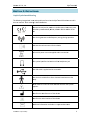
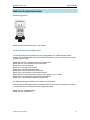
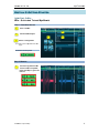
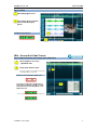
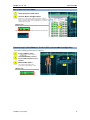
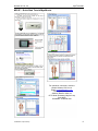
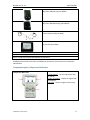
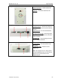
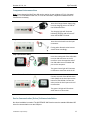
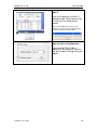
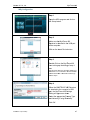
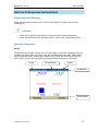
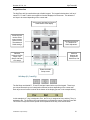
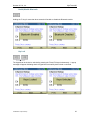
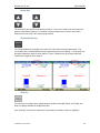
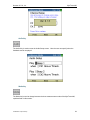
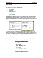
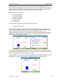
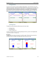
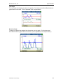
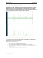
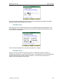
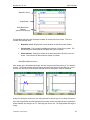
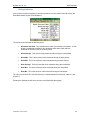
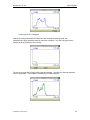
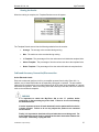
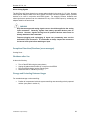
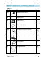
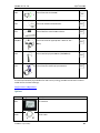
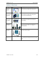
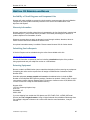
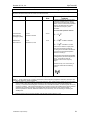
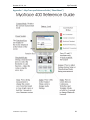
Noraxon U.S.A., Inc. MyoTrace 400 MyoTrace 400 User Manual P-0428 Rev G (June 2013) Noraxon U.S.A., Inc. MyoTrace 400 For questions, concerns or additional assistance please contact Noraxon or its Authorized Representative as specified below. M Manufacturer: Noraxon U.S.A. Inc. 15770 North Greenway-Hayden Loop, Suite 100 Scottsdale, AZ 85260 Tel: (480) 443-3413 Fax: (480) 443-4327 Email: [email protected] Support Email: [email protected] Web Site: www.noraxon.com P Authorized European Representative: Advena Ltd. Pure Offices, Plato Close, Warwick CV34 6WE, UK Telephone +44(0)1926 800153 +44(0) 845 094 3307 Email: [email protected] Website: http://www.advenamedical.com Skype: advenamedical C 0473 Notified Body: Clearance to market this product in the European Community has been certified by Notified Body #0473, AMTAC of the UK. © Copyright, 2013, Noraxon U.S.A. Inc. No part of this document may be copied, photographed, reproduced, translated, or reduced to any electronic medium or machine-readable form without the prior written consent of Noraxon U.S.A. Inc. Noraxon is a registered trademark of Noraxon U.S.A. Inc. All rights reserved. All other company and product names contained herein may be trademarks or registered trademarks of their respective companies and are sole property of their respected owners. P-0428 Rev G (June 2013) i Noraxon U.S.A., Inc. MyoTrace 400 Table of Contents Section 1: Introduction Brief Description ...................................................................................................... 1 Intended Use .......................................................................................................... 1 Contraindications ...................................................................................................... 1 Section 2: Definitions Graphic Symbols and Meanings............................................................................... 2 Glossary of Terms ................................................................................................... 3 Section 3: Identification Model Designation ................................................................................................... 4 Product Versions and Configurations ...................................................................... 4 Section 4: General Warnings and Cautions Risks and Benefits .................................................................................................... 5 Safety Information Summary ................................................................................... 5 Section 5: Getting Started Quick Start Guides .................................................................................................. 6 Section 6: Preparing the Product for Use (Setup Instructions) Unpacking and Component Identification ................................................................10 Component Inputs, Outputs and Indicators ..............................................................11 Component Interconnections ...................................................................................13 Device Communication (Driver) Software Installation .............................................13 Companion Software Installation .............................................................................14 Companion Software Configuration ........................................................................14 Section 7: Pre‐use Check‐out Normal Appearance of Signals .................................................................................18 Attaching to Patient or Subject .................................................................................18 Calibration.................................................................................................................18 Section 8: Operating Instructions Safety Information Summary ....................................................................................19 Operation Components ............................................................................................19 Normal Functions with Interface in PC .....................................................................29 Secondary Functions without PC Interface ..............................................................30 Cable and Accessory Connection/ Disconnection....................................................37 Exceptional Functions/Situations (error messages) .................................................38 Shutdown after Use ..................................................................................................38 Storage and Protecting Between Usages ................................................................38 Section 9: Accessories and Optional Modules Accessories ..............................................................................................................39 Options .....................................................................................................................40 Interfaces to Other Devices ......................................................................................41 P-0428 Rev G (June 2013) ii Noraxon U.S.A., Inc. MyoTrace 400 Section 10: Cleaning Safety Precautions When Cleaning ..........................................................................42 Cleaning by Users ....................................................................................................42 Section 11: Maintenance Safety Precautions When Performing Maintenance.................................................43 Maintenance by Users ..............................................................................................43 Maintenance by Qualified Individuals .......................................................................43 Section 12: Trouble‐shooting, Fault Diagnosis Troubleshooting Chart ..............................................................................................44 Website Link to FAQ .................................................................................................44 Radio Considerations ...............................................................................................45 Setting the Network ..................................................................................................45 Section 13: Service and Repair Availability of Circuit Diagrams and Component Lists .............................................46 Warranty Information ................................................................................................46 Submitting Service Requests ...................................................................................46 Returning Equipment ................................................................................................46 Section 14: List of Spare Parts and Consumables Consumable Items (electrodes and sensor elements) .............................................47 Replaceable Items (fuses, batteries, lead sets) ......................................................47 Section 15: Taking Product Out of Operation Disposal of Equipment and Batteries .......................................................................48 Section 16: Specifications of the Product Expected Useful Lifetime ..........................................................................................49 Dimensions and Weight ...........................................................................................49 Performance Characteristics ...................................................................................49 Energy Consumption, Condition of Use ..................................................................50 Environmental Conditions for Storage and Transport .............................................50 IP (Ingress Protection) Rating ..................................................................................50 Section 17: Technical Information Block Diagram .........................................................................................................51 Theory of Operation .................................................................................................52 Electro-Magnetic Compatibility (EMC Tables) .........................................................53 Section 18: Appendices Appendix A—Use of Disposable Electrodes ............................................................56 Appendix B—Radio Regulatory Statements ...........................................................58 Appendix C—MyoTrace 400 Reference Guide ........................................................59 P-0428 Rev G (June 2013) iii Noraxon U.S.A, Inc. MyoTrace 400 Section 1: Introduction Brief Description The MyoTrace™ 400 is a versatile portable handheld, two or four channel EMG and sensor instrument. In addition to EMG, force transducers, goniometers, inclinometers, accelerometers, and hand dynamometers can be used to assist the clinician in objectively evaluating the functional status of the musculo-skeletal system. The MyoTrace 400 offers an open ended expansion path to meet present and future neuromuscular measurement needs of any clinic or training center. As a stand-alone unit, the numerous features include a full-color bright display for 2 channels, easy visibility with internal software that is user friendly, yet flexible. As a SEMG-feedback unit, the thresholds, scale, work/rest times, mode selection are all easily accessible and menu driven. It may also be used as a measurement device to measure force, Range of motion, hand-grip strength and more with Noraxon’s sensors. Although completely self-contained, the MyoTrace 400 may also be connected to a PC via USB cable or as a telemetry unit via Bluetooth. While connected to a PC, the MyoTrace unit may be used as to measure 2 or up to 4 channels of SEMG for evaluations or feedback, or may also be used with any of the remaining Noraxon sensors, alone, or in conjunction with SEMG. This allows for an in more advanced analysis with our MyoResearch XP software. Intended Use The MyoTrace 400 system is intended to measure and quantify muscle biopotential signals separately or in combination with other kinematic or kinetic signals. This information can be used to affect muscle training and reeducation. The MyoTrace system is designed for the busy clinician interested in accurate and quick measurements. The user-friendly, menu driven operation is ideal for clinicians in orthopedic, neurological, clinical sports training and ergonomic settings. Intended Users Researchers and individuals trained in physical medicine, physical therapy or ergonomics Subject Populations – Medical Individuals with cerebral palsy, physical injuries, post surgical or post stroke conditions Subject Populations – Non medical Athletes, workers at their worksite, subjects in new product trials Common Applications Tracking over time the outcome of surgical, therapeutic or orthotic interventions; identification of ergonomic stress factors in the workplace or new product designs Contraindications Use of the MyoTrace 400 is contra-indicated in individuals who have implanted pacemakers. P-0428 Rev G (June 2013) 1 Norax xon U.S.A., In nc. MyoTrace 40 00 Sec ction 2: Definitions Graphic Symbolss and Meaning The fo ollowing international icons s and symbols are found o on the MyoTra ace 400 enclo osures and in this user manual. Their T meaning g is described d below. Approval to m A market this prooduct in the EEuropean Com mmunity wass ce ertified by No otified Body ##0344, KEMA A or #0473 AM MTAC of the UK. U The device gen T nerates radioo frequency energy during operation. In ndicates the vvolume contrrol for the devvice A 5 Volt DC po A ower source iss applied to tthis connectio on. This symbol sp T pecifies the loocation of thee headphone jack The USB cable T e is applied too this connecttion. The device is s T suitable for a direct electriical attachmeent to the body. b Read material R in the Instru ction Manuall wherever th his symbol appears. Id dentifies the m manufacture r of the devicce. P-0428 8 Rev G (June 20 013) Id dentifies the sserial numbe r of the devicce. Additional info A ormation ava ilable in a sep parate docum ment 2 Noraxon U.S.A., Inc. MyoTrace 400 Glossary of Terms Active Lead – Cable connections from the MyoTrace 400 to electrodes on the test subject Bluetooth – Wireless technology used for the exchange of data over short distances using shortwavelength radio transmissions Channel – represents any of the four measurable signals designated as Channel 1 though Channel 4 MT400 – Abbreviation for MyoTrace 400 Multi-Channel Sensor – Certain Sensor Types provide more than one signal. Thus a MultiChannel Sensor behaves like two or three standard Sensors. An example is a 3-D Accelerometer that provides acceleration data for the x, y and z directions. Sensor Type – Refers to different models of Sensors. Each sensor model measures a given type of physical parameter. Different Sensor Types can be combined in the same network. The most common Sensor Type is EMG. Examples of other types include Accelerometers, Goniometers and Force sensors. P-0428 Rev G (June 2013) 3 Noraxon U.S.A., Inc. MyoTrace 400 Section 3: Identification Model Designation Model 042 MyoTrace 400 Receiver (1 per system) Product Versions and Configurations The model 042 MyoTrace 400 Receiver can accommodate up to 4 EMG and other kinetic sensors. The standard model 042 MyoTrace 400 EMG Sensors can be combined with any of the following Sensor Types. Model 300-x In-Line Footswitch probe with x FSR sensors Model 300 IS In-Line Footswitch Probe with Insoles Model 314 In-Line Inclinometer Model 317 In-Line 3D Accelerometer Model 308 In-Line Electrical Goniometer Model 304 In-Line 1D Mechanical Goniometer Model 324 In-Line Flexiforce Local Pressure Sensor Model 320/321 In-Line Force Sensor (specify 320 = 500Lb or 321 = 100Lb) Model 328 In-Line Hand Grip Dynamometer (Biofeedback) Model 329 In-Line Scientific Hand Grip Dynamometer For additional equipment details refer to Section 9 of this manual. As the MyoTrace 400 System requires software to perform its function, the equipment is offered in combination with the following computer program packages. Model 130-133 MyoResearch-XP Model 430-433 myoMUSCLE P-0428 Rev G (June 2013) 4 Noraxon U.S.A., Inc. MyoTrace 400 Section 4: General Warnings and Cautions Risks and Benefits There is no identified risk of physical harm or injury with use of the MyoTrace 400 product. The benefit provided by use of the device is the provision of objective measures to assess the severity of pathological human movement conditions and gauge any subsequent improvement offered by therapy, training, prosthetic alterations or ergonomic design changes. Safety Information Summary Cautions Never use the MyoTrace 400 System on a person with an implanted pacemaker Never operate the MyoTrace 400 System within 1 meter of any critical medical device Warnings Do not immerse the DTS Sensors in any water or liquid Do not use the MyoTrace 400 equipment on individuals undergoing MRI, Electro Surgery or Defibrillation The MyoTrace 400 product produces results that are informative, not diagnostic. Qualified individuals must interpret the results Attention The operator must be familiar with typical characteristics of the signals acquired by the MyoTrace 400 equipment and be able to detect anomalies that could interfere with proper interpretation. P-0428 Rev G (June 2013) 5 Norax xon U.S.A., In nc. MyoTrace 40 00 Sec ction 5: Getting g Starte ed Quicck Start Guiides MR3 3 – Quick Start S Tutoriial MyoMus scle Step 1: Home/Sta art Screen 1 Select a mod dule 2 Select/create e a subject 2 1 3 3 Select a conffiguration ext (To create a new conffiguration see ne page) Continue to next ste ep with: Step 2: Measure 1 Check the signals s from th he sensors and d, if acceptable, follow the stteps in green the tool bar. P-0428 8 Rev G (June 20 013) 6 Norax xon U.S.A., In nc. MyoTrace 40 00 Step 3: Viewer 1 Review/Replay R y the record 2 Set S a marker at a each start and a end e of a desire ed analysis period p 2 Contin nue to next step p with: 1 MR3 3 – Generall Quick Sta art Tutoriall Step 4: Report Se election and Analysis Perriod Definitio on 1 Select a Re eport in one of the MyoMusc cle tabs 2 Study repo ort definition (Info) 1 Each report come es with a pre-configure ed mode for analysis period definition which w is explained herre. Co ontinue to Period Definition Vie ewer with: The Viewer is sho own again: place e marker at each start/end of analysis a period ds or confirm aced in first existing marker pairs (already pla ewer) and click: vie 2 Co onfirm or change the analysis period defintion and continue with: P-0428 8 Rev G (June 20 013) 7 Norax xon U.S.A., In nc. MyoTrace 40 00 Step 5: Read and Print a Repo ort 1 Scroll through the reporrt results 2 Use Print, View V or Analy ysis Options Reports can be printed, p copied to clipboard or exported to se everal files formats. The rep port can be Re-analyze ed to adjust the period d definition or to perform a comparison analysis. Averag ged angle patterns can n be stored as normative data orr group data 2 Co ontinue with: 1 To get g back to the start sc creen or press measure to perform the nextt measurement: Optional step in n Home/Mea asure: Crea ate or Edit a measurem ment configu uration - click on o New or Modify fy configuration in n Home or Measure - 1 Insert or de elete a device 2 Use Human n model or sensor list to selec ct or deselect in-line sensors 3 Measureme ent Options by dragging a device in or from the list of “available deviices You can add Rec cording Options, Online Processing and Feedback F Options if ne eeded 2 1 3 Co ontinue with: P-0428 8 Rev G (June 20 013) 8 Noraxon U.S.A., Inc. MyoTrace 400 MR-XP – Quick Start Tutorial MyoMuscle For questions, comments, concerns contact Noraxon USA, Inc at: Email: [email protected] Phone: (480)-443-3413 Address: Noraxon USA, Inc 15770 North Greenway-Hayden Loop Suite #100 Scottsdale, AZ 85260 USA P-0428 Rev G (June 2013) 9 Noraxon U.S.A., Inc. MyoTrace 400 Section 6: Preparing the Product for Use (Set-up Instructions) Unpacking and Component Identification The MyoTrace 400 System is provided with a padded suitcase for protection during transport and for storage. The contents are secured in recessed areas of the padding as illustrated. Carefully remove all contents and verify the following components are present. MyoTrace 400 Receiver (part #042) Battery Charger 5V Supply (part #PSU4) A to mini‐B USB Cable (part #CBL17) MyoTrace 400 Stereo Headphones (part #042C) P-0428 Rev G (June 2013) MyoTrace 400 Desk Stand (part #042E) 10 Noraxon U.S.A., Inc. MyoTrace 400 MyoTrace 400 Belt Clip (part #042E) MyoTrace 400 Wall Hanger (part #042G) Clinical Active Leads (part #244) PC Interface (part #044) Additional contents not illustrated Sample electrodes (typically dual electrodes part #272) MyoTrace 400 User Manual (part #0428) This document If additional accessories have been included please see Section 9, Accessories for component identification. Component Inputs, Outputs and Indicators 1 MyoTrace 400 (Front) P-0428 Rev G (June 2013) 1 Power Switch – Turns the MyoTrace 400 on and off 2 Color TFT Display – Display for signals and biofeedback 3 Keypad – Used to navigate device setup 11 Noraxon U.S.A., Inc. MyoTrace 400 2 MyoTrace 400 (Back) 1 Mounting Button – used to mount the MT400 to a wall 2 Speaker – broadcasts audio from the device 3 MyoTrace 400 (Top) 2C EMG Sensor (top edge) 1 Volume Control – controls the volume of the audio; used to turn the volume level up or down 2 Bluetooth Slot – for inserted Bluetooth card 3 Charge Indicator Light –illuminates when the MT400 is charging and turns off when it is done charging 4 Charger Jack – insert charging connector here to charge the MT400 1 Power Switch – Turns the power on (I) and off (O) 2 Headphone Jack – Insertion site for headphones Note: The Headphone Jack is designed for use with headphones only. Do not connect speakers or any other device to the headphone jack. P-0428 Rev G (June 2013) 12 Noraxon U.S.A., Inc. MyoTrace 400 Component Interconnections Note: Once charged, the MyoTrace 400 can be used on its own (without a PC) for 2 channel analysis. To record data for later use, or to use all 4 channels, companion software and a PC Interface are necessary. Step 1 Step 2 Step 3 (PC Interface ONLY) Step 4 (PC Interface ONLY) Insert the Charger Power Supply plug into the charging jack on the side of the DTS Belt Receiver. The charging light will illuminate indicating charging and will turn off when the MT400 is finished. Insert the active leads into the input connectors. If using other biomechanical sensors attach those accordingly. Insert the mating end of the USB cable into the USB connector on the PC Interface. Insert the opposite end of the USB cable into an available USB port on the computer. The green Power light will illuminate to indicate a connection with the PC. Connect one end of the MT400 Serial Cable (044A) to the Serial port on the bottom of the MT400. Connect the other end to the Serial port on the PC Interface box. The green Link light will illuminate when there is a connection. Device Communication (Driver) Software Installation No driver installation is needed. The MYOTRACE 400 Receiver uses the standard Windows HID driver for communication over the USB port. P-0428 Rev G (June 2013) 13 Noraxon U.S.A., Inc. MyoTrace 400 Companion Software Installation The MyoTrace 400 System is compatible with several different software programs. Identify the companion software that accompanied the equipment (MyoResearch or MR3) and follow the appropriate instructions given next. MyoResearch XP Installation 1. 2. 3. 4. 5. 6. Insert the MyoResearch XP Software CD into the PC. A menu will automatically pop up. Click on “Install MRXP” and follow the Wizard’s instructions. When the Wizard requests a password, enter the password printed on your CD case. After installing MRXP exit (close) the MRXP software. Click on “Install Patch” and follow the Wizard’s instructions. The installed companion software must be activated before unrestricted use is possible. 1. 2. 3. 4. 5. Open MRXP. A dialog box will indicate how many more times MRXP can be opened. Click on “Enter Activation Code”. Call or email Noraxon Support with the provided Activation Key. Please include the following: Your name, Company/Organization Name, Serial Number on MyoTrace 400 Receiver and the Activation Key. 6. Noraxon Support will email or respond by phone with the Activation Code 7. Enter the provided Activation Code to remove any restrictions on use. MR3 Installation 1. Insert the MR3 Software CD into the PC 2. A menu will automatically pop up 3. Click on “Install MR3” and follow the Wizard’s instructions Companion Software Configuration Before the MyoTrace 400 system can be used, the companion software must be configured to recognize the different components that make up the system. Refer to the following configuration instructions for the particular program (MyoResearch or MR3) supplied with the MyoTrace 400 System. P-0428 Rev G (June 2013) 14 Noraxon U.S.A., Inc. MyoTrace 400 MyoResearch XP Configuration Step 1 Open the MyoResearch XP program and click on the Measure button. Step 2 Click on the Hardware button Step 3 Select (click on) the MyoTrace 400 icon from the various devices at the top of the screen. P-0428 Rev G (June 2013) 15 Norax xon U.S.A., In nc. MyoTrace 40 00 Sttep 5 Cllick on the S Settings Icon n ONLY if ussing Bluetoo oth. Otherwisse press OK K to continue to the Measurrement sccreen. No ote: If the MYOTR RACE 400 Receiver is not con nnected to the co omputer the follo owing message wil l appear instead of the dialog in sstep 6. Sttep 6 (only iis using Blu uetooth) W When the MY YOTRACE 40 00 is att ttached to the computer’’s USB port, th e MyoTrace e 400 Setting gs Dialog willl ap ppear. P-0428 8 Rev G (June 20 013) 1 16 Norax xon U.S.A., In nc. MyoTrace 40 00 MR3 Configuration Sttep 1 Op 3 program a and click on pen the MR3 th e Setup buttton. Sttep 2 M ake sure the e MyoTrace 400 Re eceiver is atttached to th he USB port off the computter. Cllick on the In nsert Device e button Sttep 3 Do ouble-Click o on the MyoT Trace 400 Ico on to bring u up the dialog g of step 4. No ote: Th he MyoTrace 40 00 Icon will nott be displayed if the e device is not connected to tthe PC interfacce via a the serial cab ble or Bluetooth h. If absent go ba ack to step 2. Sttep 4 W When the MY YOTRACE 40 00 Receiverr is attached to the computer’s USB po ort, the MyoT Trace 400 S Settings Diialog will app pear as show wn. Se elect the app propriate Pre eamp Type an nd Network ((if using Blue etooth). Cllick OK P-0428 8 Rev G (June 20 013) 1 17 Noraxon U.S.A., Inc. MyoTrace 400 Section 7: Pre-Use Check-Out Normal Appearance of Signals When plugged into its charger, the MyoTrace 400’s charging light will glow amber to indicate charging. Once it is fully charged the light will go out. The PC Interface has two indicators: Power and Link. When the PC Interface is connected to the PC via USB cable, the Power light will illuminate green indicating a connection to the PC. When the PC Interface is successfully connected to the MyoTrace 400, via Bluetooth or serial cable, the Link light will illuminate green. While the MyoTrace 400 is connecting to the PC Interface there are a number of icons that will appear in the upper right corner of the MT400’s display screen. See Section 8 for more details on the icons that will appear. Connecting the Active Leads to a Patient or Subject Care should be taken to avoid accidental contact between connected but unapplied active leads and other conductive parts including those connected to protective earth. If the MyoTrace 400 was purchased without a PC Interface, the only setup required is to connect the active leads to the channel inputs. The active leads (or other Noraxon sensors) are attached to the connectors labeled 1-4 on the bottom of the MyoTrace 400. The snaps of the active leads are then applied to the electrodes on the patient. One of the leads will have a longer, third lead available for attachment to the reference electrode. For proper operation the EMG electrode must be applied to the measurement site so that the reference electrode is in direct contact with bare skin. Some skin preparation for the reference node site may be beneficial if the EMG signal exhibits a wandering baseline. See Appendix C. The active leads can be secured in place using Noraxon supplied elastic straps. Straps are recommended if dynamic movements are expected. Both snap (or button) style and pinch (or clip) style wire terminations are available. Noraxon also offers extension lead wires for special needs. Calibration If using with MyoResearch-XP or MR3 software, instruct the subject to relax all muscles for one second at the start of each measurement. (Data collected during the first second of a measurement is used to correct for any offset present in the electrodes or electronics.) P-0428 Rev G (June 2013) 18 Noraxon U.S.A., Inc. MyoTrace 400 Section 8: Operating Instructions Safety Information Summary Strictly follow all safety practices given in section of this manual. The most critical ones are repeated here. CAUTIONS Never use the MyoTrace 400 System on a person with an implanted pacemaker Never operate the MyoTrace 400 System within 1 meter of any critical medical device Operation Components Display The MyoTrace 400 contains a bright, color TFT LCD display. A status bar is displayed at the top containing information about the current mode, the Threshold/Scale button state, battery status, and the connection status. At the bottom of the screen is a menu bar containing the “Soft Key” button labels. (See the Soft Keys portion of the Keypad Interface section for more detail) Current Threshold/Scale Battery Connection Soft Key Menu P-0428 Rev G (June 2013) 19 Noraxon U.S.A., Inc. MyoTrace 400 Connection Status The current Connection Status is displayed in an icon in the upper right corner. This icon represents the state of the connection to a PC. The MyoTrace 400 may be connected to a PC via the Noraxon PC Interface. The connection to the PC Interface is made by either a serial cable or a wireless Bluetooth module. Below is a table of all possible Connection Status icons. No connection. The MyoTrace 400 is connected via the serial cable. Bluetooth is disabled and the serial cable is not connected. (Bluetooth is enabled/disabled by holding the F1 Key for more than three seconds.) Bluetooth is searching for the PC Interface. These two icons alternate every second. The MyoTrace 400 is connected via the Bluetooth module. P-0428 Rev G (June 2013) 20 Noraxon U.S.A., Inc. MyoTrace 400 Keypad Interface The MyoTrace 400 is controlled through a flexible keypad. The keypad includes three “soft keys” named F1, F2 and F3 which are mapped to functions displayed on the screen. This allows the soft keys to be reused depending on the current task. Soft keys are assigned to functions at the bottom of the display Arrow keys are used to select menu items as well as set the Threshold and Scale settings Sets the Arrow keys to Threshold or Scale Adjustment Switches between the Bar Graph, Line Graph, and Dual Line Graph Switches between the Continuous, Work/Rest, and Enters the Audio Setup screen Soft Keys (F1, F2 and F3) The Soft Keys are labeled F1, F2 and F3 and are located at the top of the keypad. These keys are unique because they are re-assigned to different functions depending on the current task. Each keys current function is shown at the bottom of the display (as seen in the example below.) In this example the F1 key is assigned to Prev, the F2 key is assigned to Next, and the F3 key is assigned to Ok. The Soft Keys are used extensively to navigate the menus of the MyoTrace 400. The F2 and F3 keys also have a special use as explained in the Key Lock section below. P-0428 Rev G (June 2013) 21 Noraxon U.S.A., Inc. MyoTrace 400 Enable/Disable Bluetooth Holding the F1 key for more than three seconds will enable or disable the Bluetooth module. Key Lock The keypad can be locked or unlocked by pressing the F2 and F3 keys simultaneously. A popup message will appear indicating that the keypad has successfully been locked or unlocked. P-0428 Rev G (June 2013) 22 Noraxon U.S.A., Inc. MyoTrace 400 Arrow Keys The Arrow Keys are used for three primary functions. They can be used to set the Threshold or Scale of each channel (channel 1 or channel 2) during measurement. They are also used to select an item from a list in the various setup screens. Threshold/Scale Key The Threshold/Scale key changes the function of the Arrow Keys during measurement. The current state of the Threshold/Scale function appears at the top of the display. If set to Scale, the Arrow Keys adjust the scale for each channel. If set to Threshold, the Arrow Keys adjust the Threshold (or target) for each channel. View Key The View key is normally used to switch between the three views (Bar Graph, Line Graph, and Dual Line Graph) available in the MyoTrace 400. If the View Key is held for more than three (3) seconds, the firmware version is displayed. P-0428 Rev G (June 2013) 23 Noraxon U.S.A., Inc. MyoTrace 400 Audio Key The Audio Key is used to enter the Audio Setup screen. Here the user can specify when the feedback sounds are played. Mode Key The Mode key is used to change between the three measurement modes of the MyoTrace 400, explained later in this section. P-0428 Rev G (June 2013) 24 Noraxon U.S.A., Inc. MyoTrace 400 Basic Operation This section covers the basic operation of the MyoTrace 400. The tasks covered in this section are common to all three Modes. The tasks include: Channel Settings Audio Settings Setting the Threshold Setting the Scale Switching Views Channel Settings Each Mode requires that the required sensor be selected for channels 1 and 2. When switching between modes, the first screen to appear is always the Channel Setup screen. The Channel Setup screens are identical with the exception of the Template Mode Channel Setup screen. The Template Mode Channel Setup includes a Template Time setting which is discussed further in the Template Mode section. The Channel Setup screen allows the user to select a predefined sensor from the list for each channel. The current channel is highlighted and its value can be changed with the Arrow Keys on the keypad. The Prev and Next Soft Keys are used to highlight the previous or next setting. This method of setting and selecting options is used throughout the MyoTrace 400. If the user chooses none for a channel, that channel will not appear in the measurement. Audio Settings The MyoTrace 400 has the ability to play sounds for biofeedback purposes. The Audio Setup screen allows the user to customize the audio feedback. The user enters the Audio Setup screen by pressing the Audio button on the keypad. P-0428 Rev G (June 2013) 25 Noraxon U.S.A., Inc. MyoTrace 400 The user can set up the audio for two cases. The Prev and Next soft keys are used to select each option and the Arrow Keys are used to change the value. In the example above, Beep 1 will play when the value of channel 1 rises above the value of channel 2. Beep 2 will play when the value of channel 2 rises above its threshold. Tones 1 & 2 are also available. The selectable audio events are: Ch1 Above Threshold Ch1 Below Threshold Ch2 Above Threshold Ch2 Below Threshold Ch1 Above Ch2 Ch2 Above Ch1 The user presses the Ok soft key to exit the Audio Setup screen. Setting the Threshold The threshold (or target) for each channel can be set independently. The threshold can be set when the MyoTrace 400 is measuring. The Ch1 Arrow Keys are used to set the threshold for channel 1 and the Ch2 Arrow Keys are used to set the threshold for channel 2. The Threshold/Scale status must be set to Threshold so the Arrow Keys adjust the threshold and not the scale. If the Threshold/Scale status area at the top of the screen says Scale, press the Threshold/Scale Key to switch it to Thresh. The threshold is indicated by a horizontal red line with a red T next to it. The actual threshold value is also numerically shown next to the line. As the user adjusts the threshold with the Arrow Keys the threshold line and number will move accordingly. If the threshold is moved beyond the limits of the graph, an arrow will appear pointing up or down, depending on the location of the threshold. The threshold number will still be visible. P-0428 Rev G (June 2013) 26 Noraxon U.S.A., Inc. MyoTrace 400 Setting the Scale The scale for each channel can also be adjusted independently. The scale sets the max value displayed on the graph. Adjusting the scale has the effect of “zooming” in or out on the data. The scale is adjusted using the Arrow Keys for each channel. The Threshold/Scale status must be set to Scale so the Arrow Keys adjust the scale and not the threshold. If the Threshold/Scale status area at the top of the screen says Thresh, press the Threshold/Scale Key to switch it to Scale. Switching Views The MyoTrace 400 provides three different ways to look at the data: Bar Graph View Line Graph View Dual Line Graph View The user can switch between the views by pressing the View key. (Note: The Template Mode only allows the Dual Line Graph view.) Bar Graph The Bar Graph View displays the data as a vertical bar graph. When the bar rises above the threshold (or below for negative thresholds) that portion of the bar turns red. P-0428 Rev G (June 2013) 27 Noraxon U.S.A., Inc. MyoTrace 400 Line Graph The Line Graph View displays the data in line graphs. For Continuous and Work/Rest Modes the graph width is 20 seconds. (This is adjustable in the Template Mode.) Dual Line Graph The Dual Line Graph View displays both channels on one line graph. For Continuous and Work/Rest Modes the graph width is 20 seconds. (This is adjustable in the Template Mode.) P-0428 Rev G (June 2013) 28 Noraxon U.S.A., Inc. MyoTrace 400 Normal Functions with Interface to a PC If the MyoTrace 400 was shipped with a PC Interface, it can be used to record data in MyoResearch-XP or MR3. The MyoTrace 400 can be connected via a serial cable or an optional Bluetooth module. During measurement the patient can see the bars/graphs on the handheld display. When used with the companion software the MyoTrace 400 System displays and records raw or processed EMG waveforms that will appear similar to the following: Consult the user manual for the companion software for descriptions of the setup, playback and analysis of the data acquired by the MyoTrace 400 system. The MT400 can connect to the PC via multiple methods: USB and WiFi using a Bluetooth card with a Noraxon PC interface with Bluetooth card. USB connection directly to the PC 1. Insert the serial cable into the Serial Port of the MT400. 2. Insert the other end of the serial cable into the Serial Port of the PC Interface. 3. Insert the USB cable into the USB port of the PC and the other end into the USB port of the PC Interface. 4. Configure the software for USB and start a measurement. P-0428 Rev G (June 2013) 29 Noraxon U.S.A., Inc. MyoTrace 400 Bluetooth card The Bluetooth card is the primary transport for sending data to the PC. To start a measurement with the Bluetooth card: 1. Make sure the Bluetooth card is inserted into both the MT400 and PC Interface. 2. Ensure that Bluetooth is enabled in the MT400 by holding down the F1 button. A screen will pop up indicating if Bluetooth is “Enabled” or “Disabled.” 3. Insert the USB cable into the USB port of the PC and the other end into the USB port of the PC Interface. 4. Configure the software for USB and start a measurement. Secondary Functions without PC Interface The MT400 has the ability to display data directly on the screen. This allows users to see signals and utilize biofeedback in areas where a PC is not present. A patient performs the prescribed activities and the results are displayed on the screen. The MT400 has three main modes: Continuous, Work/Rest, and Template. The user may choose between the modes by pressing the Mode button. Continuous Mode: In Continuous Mode the MyoTrace 400 acts as a simple biofeedback device. It allows the user to quickly start a biofeedback session with bar or line graph and audio feedback. During the session the MyoTrace 400 records the average, maximum, and minimum values measured on each channel, all of which can be viewed in a results screen. To enter Continuous Mode, press the Mode key until Continuous Mode appears at the top of the screen. The status bar is always blue while in Continuous Mode. The user may set up each channel and the Audio settings as explained in the Basic Operation section and then press the Ok soft key to continue. During measurement the user may change the current view and adjust threshold and scale settings. P-0428 Rev G (June 2013) 30 Noraxon U.S.A., Inc. MyoTrace 400 Min/Max vs. Continuous Values The Continuous Mode can report the EMG/Sensor values in two different ways: Continuous or Min/Max. If the MyoTrace 400 is set to Continuous, the current value will be displayed and updated every 500ms. If Min/Max is selected the minimum and maximum values will be displayed instead. The F1 soft key allows the user to switch to the opposite mode. While the MyoTrace 400 is displaying the Min – Max values, the user may press the Reset soft key (F2) to reset the min/max values on the screen. The Reset key will not affect the min/max values displayed in the Results screen. Results After the user is done with a session, they may either press Mode to return to the Channel Setup screen or Results to view the results from the session. The Session Results screen lists the session time as well as the average, maximum and minimum values from the session. When finished reading the results, the user may press Ok to return to the Channel Setup screen. Work/Rest Mode The Work/Rest Mode allows the user to set up a timed biofeedback session. The work time, rest time, and number repetitions may be defined by the user. The user may enter the Work/Rest Mode by pressing the Mode key until Work/Rest Mode appears at the top of the screen. The status bar is always green while in Work/Rest Mode. P-0428 Rev G (June 2013) 31 Noraxon U.S.A., Inc. MyoTrace 400 The user may select the desired sensors and set the Audio settings as described in the Basic Operation section and then press Ok to continue. Work/Rest Setup After pressing Ok in the Channel Setup screen, the Work/Rest Setup screen will appear. This screen allows the user to select the number of seconds for the work and rest phases as well as the number of work repetitions. Once the desired settings are set, the user may press Ok to continue. Work/Rest Screen When the user first enters the measurement screen, the Work/Rest session is paused, as indicated by a blinking “W” on the left side of the screen. This allows the user to set the threshold and scale settings before actually starting the session. The user may also set the zero or baseline level by pressing the Zero soft key. P-0428 Rev G (June 2013) 32 Noraxon U.S.A., Inc. MyoTrace 400 Repetition Count Progress Bar Work/Rest Phase Indicator (blinks when paused) All Work/Rest views have the Work/Rest “sidebar” at the left side of the screen. This area contains the following items: Repetition Count: Displays the current repetition as well as the total number. Progress Bar: The progress bar displays the amount of time left in a phase. The bar fills during the work phase and empties during the rest phase. Phase Indicator: Displays a W while in the work phase and a R while in the rest phase. This indicator will blink when the session is paused. Work/Rest Measurement After setting up the thresholds and scales, the user may press the Start soft key (F1) to start the session. The Phase Indicator will stop blinking and the Progress Bar will start filling up. At this time the user should be performing the required exercise and trying to meet the threshold. At any time during the session the user may press the Pause soft key (F1) to pause the session. Once the Progress Bar has filled (indicating the number of work seconds has been reached) the Phase Indicator will change to an “R”, instructing the user to rest. The Progress Bar will begin to empty. P-0428 Rev G (June 2013) 33 Noraxon U.S.A., Inc. MyoTrace 400 Ending the Session If the number of required repetitions has been reached or the user presses the End soft key the Work/Rest Results screen will be displayed. The results screen contains the following items: Work Success Ratio: This indicates the number of successful work phases. A work phase is considered successful if the measured values were higher than the threshold for more than 50% of the work period. Work Average: This is the average measured value during the work phases. Work Max: This is the maximum value measured during the work phases. Work Min: This is the minimum value measured during the work phases. Rest Average: This is the average value measured during the rest phases. Rest Max: This is the maximum value measured during the rest phases. Rest Min: This is the minimum value measured during the rest phases. The user may press the Ch1 and Ch2 soft keys to switch between the results for channel 1 and channel 2. Pressing the Settings key will return the user to the Work/Rest Setup page. P-0428 Rev G (June 2013) 34 Noraxon U.S.A., Inc. MyoTrace 400 Template Mode: The Template Mode allows the user to record a template and then train with that template. For example, a patient might perform an exercise with a healthy arm and then try to match the results using an injured arm. To enter Template Mode, press the Mode key until Template Mode appears at the top of the screen. The status bar is always gray while in Template Mode. The user sets up the sensors for each channel as described in the Basic Operation section. The Channel Setup screen for Template Mode is unique in that it also has an additional setting: Template Time. The user can select the length of the template in seconds. The allowed times are 2, 5, 10, 20, and 30 seconds. After all of the desired settings are set, the user may press Ok to continue. Recording the Template After pressing Ok, the MyoTrace 400 enters the recording screen and measurement is paused. This allows the user to prepare for the recording. At this time the user may press the Zero soft key to set the baseline level. Once the user is ready, press Start to begin recording on channel 1. The MyoTrace 400 will record until the template time has been reached. The width of the line graph is adjusted for the template time, so when the line reaches the right edge of the graph the recording is finished. P-0428 Rev G (June 2013) 35 Noraxon U.S.A., Inc. MyoTrace 400 Training with the Template After the recording has finished, the MyoTrace 400 will enter the training mode, and measurement is again paused to allow the user time to prepare. The user may again set the baseline level by pressing the Zero soft key. The user may press Start to begin training with the template. The goal is to follow the template as close as possible. The template is indicated by the shaded gray line. P-0428 Rev G (June 2013) 36 Noraxon U.S.A., Inc. MyoTrace 400 Viewing the Results When the training is complete, the Template Results screen will appear. The Template Results screen lists the following statistics from the session: Average: The average value recorded during training. Max: The maximum value recorded during training. In Template: The percentage of time the values were held inside the template limits. Above Template: The percentage of time the values rose above the template limits. Below Template: The percentage of time the values fell below the template limits. Cable and Accessory Connection/Disconnection Active Electrode Leads Each active electrode lead has a built in pre-amplifier powered from the MyoTrace 400. In addition, any of these EMG leads can be separately unplugged or replaced. The pre-amplifier electronics are contained in the removable lead and can be in either single (standard) or a double differential configuration. When connecting each lead to the MyoTrace 400, match the numbered cable to the numbered receptacle. WARNING It is important to switch the MyoTrace 400 to the “0” position before connecting or disconnecting any active lead. Failure to do so could damage the lead electronics. It is also important to have all leads detached from the patient while the device is being charged. Failure to do so may subject the patient to an unwanted electric shock. Finally, it is important to inactivate all input leads that are not being used. For active leads this can be done by placing back-to-back electrodes between the lead snaps. Alternately, unplug the lead. P-0428 Rev G (June 2013) 37 Noraxon U.S.A., Inc. MyoTrace 400 Other Analog Signals The MyoTrace 400 input channels can accept analog signals in the range of +/- 5 Volts. Noraxon offers special adapter cables that allow signals from other Noraxon supplied battery operated devices to be used in conjunction with EMG signals. For example, Noraxon footswitch and electro-goniometer products can be substituted for any of the 8 EMG inputs by exchanging an adapter cable for the active lead. WARNING Only Noraxon approved analog signal sources should be applied to the analog input connectors. Generally, signals from battery operated devices pose no concern. However, signals arriving from AC powered devices must never be directly attached to the transmitter. Frequent plugging and unplugging of inputs can prematurely wear out the transmitter input connectors. It is advisable to always inspect the connectors for bent or loose pins before attaching an input. Exceptional Functions/Situations (error messages) Coming Soon… Shutdown after Use At the end of the day: Turn off the MT400 using the power button Unplug all leads and serial cable (if in use) from the MT400 Plug the MT400 charger into the charging jack Disconnect the PC Interface (if in use) Storage and Protecting Between Usages For extended storage or when travelling: Position all components inside the system travelling case according to their prepared cavities. (see photo in section 6) P-0428 Rev G (June 2013) 38 Norax xon U.S.A., In nc. MyoTrace 40 00 Sec ction 9: Access sories an nd Optio onal Mo odules Acce essories Part N No. PSU4 BP6 044 044A 300‐xx 300‐ISS 314 317 Image De escription MT400 battery M y charger sup ply 5V More… … MT400 battery M y pack MT400 PC Inte M erface MT400 serial c M able (15 ft) In n‐Line Footsw witch probe w ith x FSR senssors n‐Line Footsw witch Probe w ith Insoles In n‐Line Inclinom meter In In n‐Line 3D Acce elerometer P-0428 8 Rev G (June 20 013) 3 39 Norax xon U.S.A., In nc. MyoTrace 40 00 308 n‐Line Force SSensor (speciffy 320 = 500Lb or 321 = In 10 00Lb) n‐Line Hand G Grip Dynamom meter (Biofeeedback) In In n‐Line Scientiffic Hand Grip Dynamometer 329 In n‐Line Flexiforrce Local Presssure Sensor 328 321 320/3 In n‐Line 1D mecchanical Goni ometer 324 304 n‐Line Electriccal Goniometeer In As new accessoriess may be available after th he time of pri nting, pleasee check Noraxxon’s website at thiss link for the latest offerings. m/products http:///noraxon.com Options No. Part N 044 Description n PC Interface e Image 044A Serial Cable e P-0428 8 Rev G (June 20 013) 4 40 Norax xon U.S.A., In nc. MyoTrace 40 00 Interrfaces to O Other Devicces age Packa Medillogic Insole es Pressure Plate (Statio onary) Im mage Descriptio n Measures ffoot pressuree profiles usin ng insoles Measures ffoot pressuree profiles usin ng a plate (Can be us ed to assess b balance) Pressure Plate (Tread dmill) Measures ffoot pressuree and center o of gravity while walkking MyoM Motion MyoV Video Measures human motio on in thee deggrees of freedom (33 DOF) 2D motion capture systtem Digitaal camera For record ing the test ssubject while they perform m trials P-0428 8 Rev G (June 20 013) 4 41 Noraxon U.S.A., Inc. MyoTrace 400 Section 10: Cleaning Safety Precautions When Cleaning WARNING Only use a damp cloth with mild soap and water or isopropyl alcohol to clean the instruments. Do not immerse any equipment in any water or liquid. Cleaning by Users The instrument case and cables can be wiped down with a damp cloth using a mild soap or detergent and water. Isopropyl alcohol can be safely used to remove tape or other adhesive residues from the cables. Before cleaning any portion of the system, the instrument should be unplugged from the wall power outlet. For sanitary purposes, it is advisable to clean the cables on a regular basis. Electrode cables can be cleaned with a solution of mild soap or detergent and water. Isopropyl alcohol can be used to remove adhesive residue from electrodes or tape. The electrode cables are not constructed to withstand repeated application of any disinfectant solution. Likewise the cables are not warranted against exposure to any of the conventional forms of sterilization. Users wishing to utilize this equipment in a sterile environment, such as an operating theater, should consult Noraxon for other options. In certain cases, cable extenders can be provided to accommodate the attachment of sterile terminal leads to the patient. P-0428 Rev G (June 2013) 42 Noraxon U.S.A., Inc. MyoTrace 400 Section 11: Maintenance Safety Precautions When Performing Maintenance No precautions required. Maintenance by Users No routine maintenance is necessary for the MyoTrace 400. Because the batteries are Li-Ion, there is no battery maintenance required. The only recommendation is to completely drain the batteries every 20-30 recharges to ensure the “fuel gauge” in the battery reports accurate charge levels. Maintenance by Qualified Individuals The following activities should only be undertaken by PC support (IT) personnel, equipment technicians or those with suitable training. Companion Software Updates Perform a backup of the data folders to a separate drive as a precaution. Click on the Patch/Update link provided in the email or as given on the Noraxon website http://noraxon.com/software-downloads Download the Patch/Update file. To install the Patch/Update, click “Run” on the dialog box. No password is required. Device Software (firmware) Updates The internal program (firmware) inside the various Noraxon devices can be updated through the use of a special utility program available at this link: http://noraxon.com/drivers-and-firmware The installed program will permit updates to the MyoTrace 400 Receive. Battery Replacement The Lithium Polymer battery used in the DTS sensors is rated for a minimum of 300 chargedischarge cycles. Typical usage is 500 charge-discharge cycles. As the number of chargedischarge cycles increases the battery capacity slowly declines thereby reducing run time despite being fully charged. Brand new batteries can operate up to 8 hours when fully charged. If the run time of the sensors drops to 5-6 hours, battery replacement should be considered. The replacement battery is part #BP6. It comes with a short pigtail wire and connector. No soldering is required. The MyoTrace 400 battery packs should not be replaced by the user. Only qualified technical personnel may perform maintenance. P-0428 Rev G (June 2013) 43 Noraxon U.S.A., Inc. MyoTrace 400 Section 12: Trouble Shooting, Fault Diagnosis Troubleshooting Chart Symptom: Problem with the PC recognizing the MyoTrace 400 System Possible Reason Remedial Action USB cable is disconnected or loose Check USB cable connection at both PC Interface and computer Check Serial cable connection at both PC Interface and MT400 Disable the power saving mode on a laptop computer. If used check that a USB hub is powered. Serial cable is disconnected or loose The USB port on the computer is in power save mode or a USB hub is not powered. Symptom: Problems with intermittent EMG signals Possible Reason Remedial Action Electrode lead set is loose or disconnected Check lead set connections at both the sensor and electrodes Move closer to PC Interface Reposition MT400 to obtain a direct line-of-sight relationship between MT400 and PC Interface Check lead set connections at both the transmitter and electrodes MT400 is too far from PC Interface MT400’s radio signal is partially blocked (absorbed) by subject’s body (esp. at long distances) Active lead set is loose or disconnected Symptom: Problems with the MT400 communicating with PC Interface Possible Reason Remedial Action Interference on wireless channel Use another radio channel (see sections 6 and 12) and make sure both transmitter and receiver are on the same RF channel Retry after charging MT400 for at least 15 minutes MT400 battery is low Website Link to FAQ Answers to common questions can be found at Noraxon’s Frequently Asked Questions (FAQ) website page at this link: http://noraxon.com/faq Other educational material is available at this link: http://noraxon.com/educational-materials P-0428 Rev G (June 2013) 44 Noraxon U.S.A., Inc. MyoTrace 400 Radio Considerations The MyoTrace 400 radio system operates in the 2400 MHz ISM (Industrial, Scientific and Medical) radio band reserved for use in most countries of the world. The radio transfers data digitally using the Bluetooth standard. Other devices operating in this frequency band include computer networks, microwave ovens, cordless phone sets and other Bluetooth enabled devices. Despite all this competing radio activity the MyoTrace 400 System is able to discern its particular information from all the surrounding radio traffic. Reliable transmission depends on good signal quality. Signal quality will fall with extended distances between the MyoTrace and the PC Interface. Obstructions (walls, metal structures, trees, etc.) between the MyoTrace and PC Interface will also lower the signal quality. While the MyoTrace 400 is quite immune to interference, it does transmit a deliberate radio signal that could affect nearby sensitive equipment. Users should always be aware of this possibility. In a similar manner, although the energy level of the radio is considered harmless to human beings, it is still prudent to minimize exposure. Finally, although available worldwide, each country places certain restrictions on the operation of radios in the 2400 MHz ISM band. These restrictions include allowable transmitter power levels and broadcast frequencies. Setting the Network The Network is the frequency used for communication between the MyoTrace 400 and the PC Interface. Typically, the default option of the Network “Network 1” (as set inside MyoResearch XP and MR3), works well. However, sometimes there is a lot of WiFi traffic in the area that may affect the data transmission between the MyoTrace 400 and the PC Interface. If there is too much traffic on the selected network, significant data loss may occur. In order to avoid data loss, changing the network to another frequency may solve the problem. If the network needs to be changed, both the PC Interface and MT400 will need to change to have corresponding networks. To select a different network number for the PC Interface, this is done in the software under MyoTrace 400 Settings. To change the network in the MyoTrace 400, hold down the F3 and Mode button simultaneously. This will cause the network screen to come up where the network can be changed using the up and down arrows on the MT400. Once both networks are changed, take another measurement to determine if the data loss problem is resolved. P-0428 Rev G (June 2013) 45 Noraxon U.S.A., Inc. MyoTrace 400 Section 13: Service and Repair Availability of Circuit Diagrams and Component Lists Noraxon will make available on request circuit schematics, component parts lists and calibration instructions to assist qualified technical personnel in the service and maintenance of the MyoTrace 400 System. Warranty Information Noraxon equipment including optional items is guaranteed to be free from defects in material and workmanship for 1 year from the date of purchase. The warrant period begins on the date of product shipment from Scottsdale, Arizona. Warranty coverage does not apply to damage incurred through accident, alteration, abuse or failure to follow instructions contained in this document. An optional extended warranty is available. Please contact Noraxon USA for further details. Submitting Service Requests A Service Request can be submitted using the online form available at this link: http://noraxon.com/service-request Provide all information requested by the form including a detailed description of the problem being experienced and your telephone number or e-mail address. Returning Equipment Be sure to obtain an RMA Number (return material authorization) before returning any equipment. Completing the online service request form will assign an RMA Number. Otherwise contact Noraxon USA. Send the equipment postage prepaid and insured to the address below. Include the RMA Number on the shipment label. Mark the package “Goods to be repaired – Made in USA” to avoid unnecessary customs charges. (Beware listing a Customs or Insurance value of $5,000.00 USD or more will result in a delay at United States Customs.) Noraxon USA 15770 N. Greenway-Hayden Loop Suite 100 Scottsdale, AZ 85260, USA If you are shipping from outside the USA please use UPS, FedEx, DHL, or EMS (US Postal Service) and not a freight-forwarder. Using a freight-forwarder incurs additional brokerage fees. If a package is shipped to Noraxon via a carrier other than the ones listed above, it may be refused. P-0428 Rev G (June 2013) 46 Norax xon U.S.A., In nc. MyoTrace 40 00 Sec ction 14 4: Spare e Parts and a Con nsumabl les Conssumable Ite ems Part No. 272 270 Image Description n Dual electroodes 8 per po ouch or 200 p per box pouch or 600 0 per box Single electtrode 30 per p Replaceable Ite ems Part No. 242P Image Description n Pre‐Amplifi ed EMG Lead d set with pinch attachmentts 242S d set with snaap Pre‐Amplifi ed EMG Lead attachmentts BP6 Replaceme nt battery forr MT400 P-0428 8 Rev G (June 20 013) 4 47 Noraxon U.S.A., Inc. MyoTrace 400 Section 15: Taking Product out of Operation Disposal of Equipment and Batteries The MyoTrace 400 EMG Sensors contain Li-Polymer batteries, which may be hazardous if disposed of incorrectly. Please check with the governing authorities in your location before disposing of the MyoTrace 400 and its contents. P-0428 Rev G (June 2013) 48 Noraxon U.S.A., Inc. MyoTrace 400 Section 16: Specifications of the Product Expected Useful Lifetime The MyoTrace 400 Receiver (#042) has a usable life of seven years. The MyoTrace 400 (#042) operates with a rechargeable Lithium Ion battery. The battery capacity will decline with ongoing use and require replacement after 300+ discharge/charge cycles to preserve the device’s rated 8 hours of operating time. Dimensions and Weight MyoTrace 400 Dimensions: 6.6875” L x 4.375” W x 1.1875” H (16.98 cm L x 11.11 cm W x 2.73 cm H) MyoTrace 400 Weight: 382.7g (13.5oz) PC Interface Dimensions: 2.5” L x 2” W x 0.81” H (6.35 cm L x 5.08 cm W x 2.06 cm H) PC Interface Weight: 45.4g (1.6oz) Performance Characteristics MyoTrace 400 Operating Specifications Operating Voltage: 2.6V to 4.2V Analog Input Volate Range: -5.0V to +5.0V Battery Charger Voltage: 5V DC Battery Life: 8 hours continuous life Battery: 4.2V Li-Ion Rechargeable Battery Serial Port Voltage Range: 0V to 3.3V 16-bit resolution Real time sampling at 1000 Hz All channels have low pass anti-alias filters set to 500 Hz Transmits data up to 20ft with use of Bluetooth and PC Interface PC Interface Electrical Specifications Operating Voltage: 5V Serial Port Voltage Range: 0V – 3.3V Power Source: 5V USB Bus Power EMG Acitve Lead Specifications Baseline noise < 1 uV RMS Input impedance > 100 Mohm CMR > 100 dB Input range: +/- 3.5 mV Base Gain: 500 High pass filter at 10Hz +/- 10% Snap-style or Pinch-style terminal electrode connections P-0428 Rev G (June 2013) 49 Noraxon U.S.A., Inc. MyoTrace 400 Energy Consumption, Condition of Use Powered by a 4.2V Lithium ion battery charged by a 5V DC battery charger. Environmental Conditions for Storage and Transport Ambient Temperature: -40C to +70C Relative Humidity: 10% to 100% Atmospheric Pressure: 500hPa to 1060hPa IP (Ingress Protection) Rating The MyoTrace 400 device enclosures have a low ingress protection rating (IP20). The MyoTrace 400 is not waterproof. Care must be taken to avoid exposure to all liquids. P-0428 Rev G (June 2013) 50 Noraxon U.S.A., Inc. MyoTrace 400 Section 17: Technical Information Block Diagram Model 042 MyoTrace 400 Model 044 PC Interface P-0428 Rev G (June 2013) 51 Noraxon U.S.A., Inc. MyoTrace 400 Theory of Operation The MyoTrace 400 is a 2 or 4 channel, portable electromyography device. It is designed in compliance with international standard IEC60601-2-40, Particular requirements for the safety of electromyographs and evoked response equipment. The EMG leads are classified as Type B applied parts. Because the leads are Type B, the MyoTrace 400 may not be used with stimulation (E-Stim) devices. The instrument contains an integral 16 bit analog to digital conversion system for all input channels. Communication with a computer system is provided by means of Bluetooth or a Serial Cable. The MyoTrace 400 is designed for continuous operation. The instrument is powered by an internal battery and is considered Internally Powered Equipment. P-0428 Rev G (June 2013) 52 Noraxon U.S.A., Inc. MyoTrace 400 Electro‐Magnetic Compatibility Tables Guidance and manufacturer’s declaration – electromagnetic emissions The MyoTrace 400 is intended for use in electromagnetic environment specified below. The customer or the user of the MyoTrace 400 should assure that it is used in such an environment. Emissions Test Compliance RF emissions CISPR 11 Group 2 RF emissions CISPR 11 Class A Electromagnetic environment - guidance The MyoTrace 400 must emit electromagnetic energy in order to perform its intended function. Nearby electronic equipment may be affected. Harmonic Emissions IEC 61000-3-2 Not applicable Voltage fluctuations/ flicker emissions IEC 61000-3-3 Not applicable The MyoTrace 400 is suitable for use in all establishments other than domestic establishments and those directly connected to the public low-voltage power supply network that supplies buildings used for domestic purposes. Guidance and manufacturer’s declaration – electromagnetic immunity The MyoTrace 400 is intended for use in electromagnetic environment specified below. The customer or the user of the MyoTrace 400 should assure that it is used in such an environment. Immunity Test Electrostatic discharge (ESD) IEC 64000-4-2 Electrical fast transient/burst IEC 61000-4-4 Surge IEC 60601 test level Compliance level ±6 kV contact ±6 kV contact ± 8 kV air ±6 kV air ±2kV for power supply lines ±2kV for power supply lines ±1kV for input/output lines ±1kV differential mode Not applicable ±2kV common mode <5 % UT (>95 % dip in UT) for 0,5 cycle ±2kV common mode Not applicable to operation 40 % UT (60 % dip in UT) for 5 cycles Not applicable to operation 70 % UT (30 % dip in UT) For 25 cycles Not applicable to operation <5 % UT (>95 % dip in UT) For 5 sec 3 A/m Not applicable to operation ±1kV differential mode IEC 61000-4-5 Voltage dips, short interruptions and voltage variations on power supply input lines IEC 61000-4-11 Power frequency (50/60 Hz) magnetic field 3 A/m Electromagnetic environment guidance Device user should avoid touching subject and sensor probes while a measurement is active. For battery charging mains power quality should be that of a typical commercial or hospital environment. For battery charging mains power quality should be that of a typical commercial or hospital environment. For battery charging mains power quality should be that of a typical commercial or hospital environment. Power frequency magnetic fields should be at levels characteristic of a typical location in a typical commercial or hospital environment. IEC 61000-4-8 NOTE UT is the a.c. mains voltage prior to application of the test level. P-0428 Rev G (June 2013) 53 Noraxon U.S.A., Inc. MyoTrace 400 Guidance and manufacturer’s declaration – electromagnetic immunity The MyoTrace 400 is intended for use in electromagnetic environment specified below. The customer or the user of the MyoTrace 400 should assure that it is used in such an environment. Immunity Test IEC 60601 test level Compliance level Electromagnetic environment guidance Portable and mobile RF communications equipment should be used no closer to any part of the MyoTrace 400, including cables, than the recommended separation distance calculated from the equation applicable to the frequency of the transmitter. Recommended separation distance Conducted RF IEC 61000-4-6 (Charging System) 3 Vrms 150 kHz to 80 MHz 3Vrms Radiated RF IEC 61000-4-3 3 V/m 80 MHz to 2,5 GHz 3V/m d 1 .2 P d 1 .2 P 80 MHz to 800 MHz d 2 .3 P 800 MHz to 2,5 GHz where P is the maximum output power rating of the transmitter in watts (W) according to the transmitter manufacturer and d is the recommended separation distance in metres (m). Field strengths from fixed RF transmitters, as determined by an electromagnetic site a survey, should be less than the compliance level in each frequency b range. Interference may occur in the vicinity of equipment marked with the following symbol: NOTE 1 At 80 MHz and 800 MHz, the higher frequency range applies. NOTE 2 These guidelines may not apply in all situations. Electromagnetic propagation is affected by absorption and reflection from structures, objects and people. a Field strengths from fixed transmitters, such a base stations for radio (cellular/cordless) telephones and land mobile radios, amateur radio, AM and FM radio broadcast and TV broadcast cannot be predicted theoretically with accuracy. To assess the electromagnetic environment due to fixed RF transmitters, an electromagnetic site survey should be considered. If the measured field strength in the location in which the TeleMyo DTS is used exceeds the applicable RF compliance level above, the TeleMyo DTS should be observed to verify normal operation. If abnormal operation is observed, additional measures may be necessary, such as reorienting or relocating the TeleMyo DTS. b Over the frequency range 150 kHz to 80 MHz, field strengths should be less than 3 V/m. P-0428 Rev G (June 2013) 54 Noraxon U.S.A., Inc. MyoTrace 400 Recommended separation distances between portable and mobile RF communications equipment and the TeleMyo DTS The MyoTrace 400 is intended for use in an electromagnetic environment in which radiated RF disturbances are controlled. The customer or the user of the MyoTrace 400 can help prevent electromagnetic interference by maintaining a minimum distance between portable and mobile RF communications equipment (transmitters) and the MyoTrace 400 as recommended below, according to the maximum output power of the communications equipment. Rated maximum output power of transmitter W Separation distance according to frequency of transmitter m 150 kHz to 80 MHz 80 MHz to 800 MHz 800 MHz to 2,5 GHz d 1 .2 P d 1 .2 P d 2 .3 P 0,01 0.12 0.12 0.23 0,1 0.38 0.38 0.73 1 1.2 1.2 2.3 10 3.8 3.8 7.3 100 12 12 23 For transmitters rated at a maximum output power not listed above, the recommended separation distance d in meters (m) can be estimated using the equation applicable to the frequency of the transmitter, where P is the maximum output power rating of the transmitter in watts (W) according to the transmitter manufacturer. NOTE 1 At 80 MHz and 800 MHz, the separation distance for the higher frequency range applies. NOTE 2 These guidelines may not apply in all situations. Electromagnetic propagation is affected by absorption and reflection from structures, objects and people. P-0428 Rev G (June 2013) 55 Noraxon U.S.A., Inc. MyoTrace 400 Section 18: Appendices Appendix A – Use of Disposable Electrodes While the MyoTrace 400 can operate with reusable electrodes, it is typically used with disposable surface electrodes. Any good quality silver/silver chloride electrode is acceptable. Noraxon provides several types of quality disposable electrodes for a wide variety of Surface EMG applications. Other electrodes may be used, but it is recommended that any electrodes used with the MyoTrace 400 satisfy the requirements for standard ANSI/AAMI EC12-1991 Disposable ECG electrodes. Because disposable electrodes have a shelf life, it is important not to use expired parts. Bulk disposable electrodes come packaged in a sealed container or bag. The expiration date can be found printed on the package container. After the sealed bulk container is opened, the remaining electrodes should be used before their gel begins to dry out. Always keep the remaining electrodes in their bulk package until they are used. If the electrode package does not seal itself, closing the package with tape or using a zippered plastic bag is recommended. Do not store the electrode package in the direct sun, as this will accelerate drying. Avoid using electrodes that are randomly found lying outside of their bulk packaging as their expiration date is uncertain and their gel has been exposed to accelerated drying. Be aware that when disposable electrodes are removed, some individuals may notice a faint red skin discoloration over the site previously occupied by the electrode. This skin discoloration is typically benign and temporary and may be due to a mild allergic reaction to the adhesive or simply be a slight abrasion caused by peeling away the tape. It will usually disappear within 24 hours. Noraxon discourages any attempt to reuse a disposable electrode, even if it is simply pulled off to slightly reposition the electrode’s muscle placement. Some of the electrode gel may remain on the original site and the EMG signal may be affected. Also, sometimes the electrode adhesive may not adhere to the skin as well when it is reapplied. Noraxon strongly recommends against the use of dried out electrodes that are re-wetted with electrode gel. Electrode Application Guidelines and Facts 1. If the subject has a fair amount of hair at the electrode application site, the hair should be clipped. Shaving is not necessary and may irritate the skin. 2. The electrode application site should be clean and dry. The preferred method of cleaning is with soap and water plus drying the skin with a dry cloth. Dry skin contributes to good electrode adhesion and good trace quality. 3. Cleaning with isopropyl alcohol should be limited to situations where electrode adhesion is an issue (diaphoresis, excessively oily or lotion covered skin), since it may dehydrate the skin thereby causing skin impedance to increase. If alcohol is used, allow it to dry prior to electrode application. 4. Noraxon recommends attaching the lead wire to the electrode prior to placing the electrode on the skin. This will eliminate the potential for discomfort if snap lead wires are pressed onto the electrode after the electrode has been applied. It will also prevent the electrode gel from P-0428 Rev G (June 2013) 56 Noraxon U.S.A., Inc. MyoTrace 400 seeping out. Additionally, this method will prevent unattached leads from coming into accidental contact with other conductive objects. 5. Electrode application sites may need to be abraded to lower the skin impedance. Fine sand paper or electrode prep gel, e.g. NuPrep, can be used to abrade the skin. 6. Electrodes are the weak link in the EMG measurement chain. Lack of proper attention to electrode quality or site preparation is by far the most common cause of inferior recordings. 7. It may take up to 5 minutes for disposable electrodes to fully stabilize electrically once applied to the skin. If extremely critical or precise measurements are intended, the electrodes should be applied several minutes in advance of the recording. Warning When attaching EMG leads, prevent lead snaps that are not yet attached to electrodes from coming into accidental contact with other conductive objects. This will avoid a potential shock hazard. A simple way to ensure this with disposable electrodes is to first attach electrodes to all snaps, unpeel the adhesive cover and apply the electrodes to the patient. P-0428 Rev G (June 2013) 57 Noraxon U.S.A., Inc. MyoTrace 400 Appendix B – Radio Regulatory Statements FCC Statement This device complies with part 15 of the FCC rules. Operation is subject to the following two conditions: (1) This device may not cause harmful interference, and (2) this device must accept any interference received, including interference that may cause undesired operation. Caution: Changes or modifications not expressly approved by the party responsible for compliance could void the user’s authority to operate the equipment. This device contains modules with FCC ID: R8KUGWG4USHN33A. Industry Canada Statement This product contains Unigen Wireless USB module Canadian Cert No IC: 5125A-UGWG4US P-0428 Rev G (June 2013) 58 Noraxon U.S.A., Inc. MyoTrace 400 Appendix C – MyoTrace 400 Reference Guide (“Cheat Sheet”) P-0428 Rev G (June 2013) 59


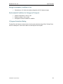

![[ENG-ITA] User's Manual UPS EVO DSP PLUS MM 1.2-2.4](http://vs1.manualzilla.com/store/data/006884869_1-f09fb11d812c485aa10a235685fba597-150x150.png)