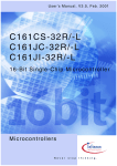
1
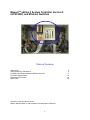
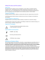
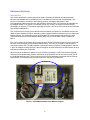
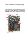
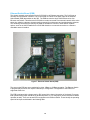
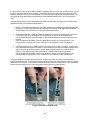
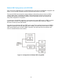
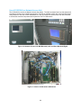
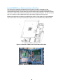
MaxumTM edition II System Controller Version 2 (SYSCON2) and Ethernet Switches Table of Contents Getting Help Safety Practices & Precautions SYSCON2 and Ethernet Boards Hardware Overview SYSCON2 Specifications Relacement Procedures Spare Parts Siemens © 2012 All rights reserved. Maxum, Maxum edition II, and Optichrom are trademarks of Siemens 1 2 3 5 18 19 30 Getting Help Contacts for Help Siemens provides support for the Maxum System worldwide. Contact information is provided on all Siemens products at the web sites noted below. This page provides contact information for Maxum System technical support, training, spare parts, and field service callout. Worldwide e-mail requests can be submitted 24 hours a day, 7 days a week. Service contracts can be established for direct remote phone service for products or for regular field service visits to the site. To Contact Us: International USA Singapore Siemens AG I IA SC PA PM Process Analytics Oestliche Rheinbrueckenstrasse 50 76187 Karlsruhe Germany Siemens Industry Inc. Siemens Pte. Limited IA SC Process Analytics 9 Woodlands Terrace Singapore 738434 Tel: Fax: E-mail: +49 721 595 4802 +49 721 595 5211 [email protected] 7101 Hollister Road Houston, TX 77040 USA Tel: Fax: E-mail: +1 713 939 7400 +1 713 939 9050 [email protected] www.siemens.com/processanalytics www.usa.siemens.com/pa Training Tel: +49 721 595 4035 E-mail: [email protected] Training Tel: +1 800 448 8224 (USA) Tel. +1 918 662 7030 (International) E-mail: [email protected] Spares Contact your local Siemens Sales Representative Support Tel: +49 721 595 7216 E-mail: [email protected] Tel: Fax: E-mail: +65 6309 1700 +65 6309 1710 [email protected] www.siemens.com.sg Spares Tel: +1 800 448 8224 (USA) Tel: +1 918 662 7030 (International) E-mail: [email protected] Support Tel: Tel: E-mail: +1 800 448 8224 (USA) +1 918 662 7030 (International) [email protected] m Before You Call When contacting Siemens Customer Service for installation technical assistance, the user will need to provide the unit serial number and a detailed description of the problem. Indicate the installation problem encountered and provide any other information that will aid the customer service representative in correcting the problem. 2 Safety Practices and Precautions Safety First This product has been designed, tested, and supplied in a safe condition in accordance with IEC Publication 61010-1, Safety Requirements for Electrical Equipment for Measurement, Control, and Laboratory Use - Part 1: General Requirements. This manual contains information and warnings which have to be followed to ensure safe operation and to maintain the product in a safe condition. Terms in This Manual WARNING statements identify conditions or practices that could result in personal injury or loss of life. CAUTION statements identify conditions or practices that could result in damage to the equipment or other property. Terms as Marked on Equipment DANGER indicates a personal injury hazard immediately accessible as one reads the markings. CAUTION indicates a personal injury hazard not immediately accessible as one reads the markings, or a hazard to property, including the equipment itself. Symbols in This Manual This symbol indicates where applicable warning, caution, or other information is to be found. Symbols Marked on Equipment DANGER - High voltage Protective ground (earth) terminal ATTENTION - Refer to Manual Hazardous or Poisonous Gases When hazardous gases (such as poisonous, flammable, or oxygen depleting) are potentially present in or around the Maxum edition II Process Gas Chromatograph (hereafter referred to as Maxum II) area, all national and international requirements must be fulfilled to protect personnel and the environment against hazards that could arise. All process conditions (such as normal, backup, and upset) must be considered in the determination for potential hazardous gas presence. To avoid leaks, scheduled preventive maintenance and inspection for leaks should be performed by the customer. Leak sources should also be minimized as is noted in the procedure by external venting of the oven exhaust and analyzer vents. This reduces (does not eliminate) the sources for leaks, so personnel protection is a requirement whenever hazardous/poisonous gases may be present. Disregarding this warning could result in serious injury or death and damage to equipment. 3 Safety Practices and Precautions, Continued Correct Operating Voltage Before switching on the power, check that the operating voltage listed on the equipment agrees with the available line voltage. Ensure that the power supply switch is set to the correct input voltage. Danger Arising from Loss of Ground Any interruption of the grounding conductor inside or outside the equipment or loose connection of the grounding conductor can result in a dangerous unit. Intentional interruption of the grounding conductor is not permitted. Safe Equipment If it is determined that the equipment cannot be operated safely, it should be taken out of operation and secured against unintentional usage. Use the Proper Fuse To avoid fire hazard, use only a fuse of the correct type, voltage rating, and current rating as specified in the parts list for your product. Use of repaired fuses or short-circuiting of the fuse switch is not permitted. Safety Guidelines DO NOT perform electrical parts replacement or repairs until all power supplies have been disconnected. Only a properly trained technician should work on the equipment with power applied. When opening covers or removing parts, extreme care should be taken since hot surfaces and "live” parts or connections can be exposed. 4 Hardware Overview Introduction This section describes the second generation System Controller (SYSCON2) and the associated Ethernet Switch Board that are available for use in the Maxum II Process Gas Chromatograph. This product is intended for use solely in the following products: the Maxum and Maxum II Gas Chromatographs, Network Access Unit, and Optichrom Advance Plus. The SYSCON2 is supported only by software version 5.0 or greater. For software version 4.3 or lower, the original version SYSCON (SYSCON+) is required. For information regarding SYSCON+, refer to the user manual for the SYSCON+ (part number 2000686-001). The SYSCON2 is the primary control board used in the Maxum, the Maxum II, the Network Access Unit (NAU), and the Advance Plus Door assembly (used to upgrade Optichrom Advance GCs to include many Maxum features. The SYSCON2 consists of two boards, the Communication and Analytical Control (CAC3) board and the SYSCON Interface Board (SIB). Only one SYSCON2 is used in a particular device. The CAC3 contains the processor and memory functions for the SYSCON2 as well as control of external Ethernet communications (via the Ethernet Switch Board). The CAC3 is mounted on and operates in conjunction with the SIB. The SIB is specific to the Maxum family of products (including Maxum, Maxum II, NAU, and Optichrom Advance Plus). With the exception of external Ethernet, the SIB contains all other interfaces provided by the SYSCON2. When housed in the Maxum or Maxum II, the SYSCON2 is mounted in a pull-out drop-down assembly, called the SYSCON assembly. External connections to the SYSCON are via connectors on the front of the SYSCON assembly cage. The far right slot of the SYSCON assembly is equipped with an Ethernet Switch Board. This board provides four connections for external 10/100 Ethernet. Figure 1: SYSCON2 Assembly in the Maxum Analyzer 5 CAC3 The Communication and Control board (CAC) is a standardized, single-board central processing unit for intended for use in Siemens products`. For the Maxum family of products the third generation of the CAC board (CAC3) is used. The CAC3 utilizes a 32-Bit, 240 MHz microprocessor. The on-board memory for the CAC3 consists of 128 MB SDRAM, 64 MB NOR Flash, and 256 MB NAND Flash. The CAC3 also includes an on-board 10/100 Ethernet controller, used for connection to external Ethernet. This is connected via a short RJ-45 patch cable to the Ethernet Switch Board, which resides in a card slot on the SIB. The communication backbone between the CAC and the SIB is the General Purpose Bus (GP Bus). The GP Bus is a 32 bit, 120 MHz parallel address/data bus with dedicated chip selects and interrupts. In addition to the GP Bus, the CAC communicates via two serial buses. One serial bus is dedicated to the serial debug port. The second serial bus provides four configurable serial communications ports (including Modbus or other basic RS-232/485 protocols). The serial and debug ports are accessed on the front of the SYSCON assembly. Figure 2: CAC3 Board 6 Figure 3: LEDs on the CAC3 Board LED LED1 LED2 Description Debug LED1 Debug LED2 LED3 LED4 Power Good Maintenance LED5 LED7 Fault Ethernet Speed Green LED on RJ-45 Link Status Yellow LED on RJ-45 Link Acknowledge Color / Meaning Green – On during normal operation. Green – On during normal operation. Off during bootload Green – Power to CAC3 is functional Yellow – Off during normal operation. On during bootload. On – Maintenance fault or bootload Red – CAC3 Board fault Green – On – Speed is 100 Mbits/sec (or auto-negotiating) Off – Speed is 10 Mbits/sec (or disconnected) Green – LED is green when link is in full duplex mode. Yellow – LED is on when link is active. Will flash off for transmit or receive activity. Table 1: CAC3 LEDs 7 SIB The SYSCON Interface Board (SIB) is a board that, when combined with the CAC3, creates the function of the SYSCON2. Unlike the CAC3, the SIB is specific to the Maxum family of products (including the Maxum, the Maxum II, NAU, and Optichrom Advance Plus). The combined SIB and CAC3 are an electrically and mechanically compatible replacement for the legacy SYSCON board in the Maxum. Other than external Ethernet, the SIB provides all interfaces for the SYSCON2. This includes the following connections (refer to figures 4 and 5 for physical connector locations): • PCI and CAN Direct Slots – The PCI slots on the SIB are designed to accommodate a variety of special function cards, including Input/Output boards or ANCB board. Four PCI slots are equipped in the SYSCON2; however, typically only three slots are available for use in the standard configuration. This is because one SYSCON assembly slot is utilized for serial/debug port hardware as shown in figure 4. Only cards specified and sold by Siemens for the SYSCON2 should be installed in the PCI slots of the SYSCON2. CAUTION – Installation of a card that is not approved by Siemens into a SYSCON2 PCI slot, may damage both the card and the SYSCON2. In addition to PCI type cards, the card slots are also capable of accommodating Maxum CAN I/O cards. There is a small green connector in line with the PCI slot that allows CAN I/O cards to be inserted in the slot. When a CAN card is installed, the green connector provides the power and CAN signals for the card. The PCI slot connector does not provide any electrical connection for CAN cards. • Serial Ports 1 and 2 – The SYSCON2 is equipped with two serial ports, each ground isolated and configurable for RS-232 or RS-485. Both ports support RTS/CTS hardware handshake. Maximum supported data rate on the serial ports is 115200 bits/second. Serial Port 1 is used to support Modbus and Serial Port 2 may be used to support a printer. CAUTION – Mixing RS-485 and RS-232 cabling/devices could possibly damage a serial device. Because of this, always verify the port settings in software prior to plugging any cable into a SYSCON serial port. Note: When configured for RS-485 operation, the serial ports are designed to comply with the Profibus standard. This results in a different pinout than for the previous version of SYSCON (pins 8 and 2 reversed). For backward Modbus RS-485 compatibility when replacing a SYSCON+ with a SYSCON2, an adapter cable (part number A5E02283873001) is available. DB-9 Pin# 1 2 3 4 5 6 7 8 9 RS-232 RX TX GND RTS CTS - RS-485 Modbus 5 V Pwr Line B (RxD+/TxD+) Common Line A (RxD–/TxD–) - Table 2: Serial Port Pinouts for SYSCON2 8 • SYSCON Debug – This serial RS-232 port is used to interface to the SYSCON2 debug function on the CAC3. The debug port has no support for hardware handshake. The debug port is accessed via a DB9 connector on the front of the SYSCON assembly cage. • Serial Ports 3 and 4 – These two serial ports, equipped on the same slot connector as the SYSCON Debug port, are planned for future expansion and are not active in software release 5.0. • Network Expansion Slot – The Ethernet Switch Board plugs into this connector, located on the far right side of the SYSCON2 as shown in figure 5. The connector slot provides power to the Ethernet Switch, but no communication. All communication between the Ethernet Switch and the SYSCON2 is through a short CAT5 Ethernet Cable that connects from the CAC3 to the Ethernet Switch. • 2 2 2 I C Bus – The I C connectors are shown in the upper right corner of figure 5. Two I C buses are 2 2 equipped on the SYSCON2. These are labeled I C Bus A and I C Bus B. ¾ I2C Bus A includes the two connectors on the right as shown in figure 5. I2C Bus A is dedicated and hard wired to the CAN Bridge function. This allows the new SYSCON2 to interface with legacy CAN I/O cards in the PCI slots. ¾ I2C Bus B includes the three I2C connectors on the left as shown in figure 5. I2C Bus B is intended for use to support future configuration changes in the Maxum II. • Analog and Digital Inputs/Outputs – The SYSCON2 allows for the configuration of up to ten on-board inputs/outputs. The connectors for these are wired from two orange connectors on the front of the SYSCON assembly cage. The pinout of these connectors is shown below. The actual pin layout with input and output signals in a delivered system will be shown in the System Documentation package. DO1–DO4 4 digital outputs: floating double-throw contacts, maximum contact load rating 30 V/ 1 A. DO1 is not administrable and is dedicated to “Maxum Fault” (active when the Maxum has an active alarm). AO1–AO2 2 analog outputs: 0/4–20 mA, common negative pole, galvanically separated from ground, freely connectable to ground, maximum gain vs. local protective ground potential 50 V, max. working resistance 750 Ω DI1–DI4 4 digital inputs: Optocoupler with internal 12–24 VDC power supply, switchable with floating contacts; alternative: switchable with external 12–24 VDC supply, common negative pole Note: There is a switch, SW3 (located near the orange I/O connectors), that controls the mode of the DIs. This switch should be set to Mode 2 regardless of the configuration unless instructed differently by Siemens. Design: Two 12-pin terminal strips for braided or solid 2 cable with maximum cross section of 1.5 mm or 16 AWG. 9 • Figure 3: System Controller I/O Connection Diagram Interface to External CAN Bus (for CEU) – This connector on the SYSCON2 is provided to allow support for the CAN Extension Unit (CEU). • Internal CAN Bus Interface – This connector is used for extension of the internal CAN bus to allow for additional CAN I/O cards. It is only used when the SYSCON2 is installed in an NAU. • Resets – The SYSCON2 is equipped with two connections for SYSCON reset. The first connection, located at the front of the board (bottom of figure 5), is a pushbutton switch. This switch may be accessed via the front of the newest version SYSCON assembly cage. The second connection consists of two pin connections at the back of the board (top left of figure 5). This second connection is provided to support legacy SYSCON assembly cages that provide a separate wired pushbutton reset. Both connections allow the user to initiate a hard reset of the SYSCON (same as initial power up). • 10BaseT to SNECON – The SYSCON2 communicates to the SNECON board using a 10BaseT ethernet connection (prior versions of the SYSCON hardware operated at 10Base2). A short CAT5 RJ-45 network cable is used to make the connection. • Purge – The purge detect circuit for the SYSCON2 works in the same manner as for the SYSCON+. The purge detect signal is received from the PECM and distributed to the HMI (purge fault LED) and handled by the SYSCON as a digital input to generate a purge alarm. • Interface to HMI Hardware – The HMI panel connects to the SYSCON2 using a parallel bus over a physical ribbon cable. This bus operates at 33 MHz to support the existing HMI hardware; however, future HMI hardware may utilize the faster bus speeds that the SYSCON2 can provide. Note that the connector used on the SYSCON2 is different than for SYSCON+. • USB Ports – The SYSCON2 hardware is equipped with three USB ports. However, these ports are planned for future use and are not currently functional. • Power – The source of power for the SYSCON2 is the 24 V power supply equipped in the Maxum analyzer. The SYSCON2 is equipped with on-board power conversion to derive the other voltages needed for operation (3.3 V, 5 V, and 12 V). The primary operating voltage of the SYSCON2 is 3.3 V. • Battery – The SYSCON2 is equipped with a long-life 3 V battery backup to support the real time clock on the CAC3 board. This battery should last at least 5 years under normal operation. Note that the battery is located on the SIB board while the real time clock is on the CAC3 board. If the CAC3 board is disconnected from the SIB, then battery backup is lost. This will affect the time and date on the analyzer. Figure 4: SYSCON2 Assembly Front Connections 10 Figure 5: SYSCON2 Connections 11 SIB LEDs and Switch Options LED Type Power Description Power (Located at the back of the board near the RJ-45 connector) Power Bad I2C Bus LEDs Buses A and B (Located next to I2C Bus connectors) CAN Bridge LEDs CAC Conn Bad LED2/5 Norm/Comm LED3/6 Warning LED4/7 Fault LED16 Ready/Comm (Located to the left of the far left PCI slot) CAN I/O LEDs LED17 LED15 LED8 Warning Fault TX (Located next to far left CAN direct connector, CAN direct 5) LED9 RX LED10 Heartbeat LED11 Fault PCI Slot LEDs LED14 Slot 0 Fault (Located between PCI slots) LED13 Slot 1 Fault LED18 Slot 2 Fault LED12 Slot 3 Fault Internal Ethernet LEDs Green LED on RJ-45 (Located next to and on SIB RJ-45 connector) Yellow LED on RJ-45 LED1 Speed Color / Meaning Green – 3.3V power is available. Should be on at all times. Red – Power is faulty or SYSCON hardware reset switch is being pressed. Red – Connection from the SIB to the CAC3 is faulty or incomplete. After power up, this LED should turn off once CAC3 to SIB connection is completely initialized. Dim Green – I2C Bus is normal. Bright Green - I2C Bus is communicating Yellow – Warning on the I2C Bus Red –I2C Bus fault Dim Green – CAN Bridge is normal Bright Green – CAN Bridge is communicating Yellow – Warning on the CAN bridge Red –CAN Bridge fault Green – On when a valid CAN I/O message (other than a heartbeat reply) has been received and queued for processing. Green – On when a CAN message (other than a heartbeat transmission) has been queued for sending to the CAN hardware. Green – Flashes once for each heartbeat message transmitted. This LED will flash once every 1.5 seconds for each active CAN card. Red – On when an error state is detected on the CAN bus hardware Red – Overcurrent or thermal shutdown on PCI slot 0. Red – Overcurrent or thermal shutdown on PCI slot 1 Red – Overcurrent or thermal shutdown on PCI slot 2 Red – Overcurrent or thermal shutdown on PCI slot 3 Green – LED is green when link is in full duplex mode Yellow – LED is on when link is active. Will flash off for transmit or receive activity. Green – On – Speed is 100 Mbits/sec (or auto-negotiating) Off – Speed is 10 Mbits/sec (or disconnected) Note: Refer to figure 6 for physical locations of SIB LEDs Table 3: SIB LEDs 12 • DI Mode Switch – Switch SW3 located near the orange I/O connectors conrols the mode setting for the on-board digital inputs. The available options are Mode 1 (source) and Mode 2 (sink). This switch should be set to Mode 2 regardless of the configuration unless instructed differently by Siemens. • Reset Switch – The function of the reset switch is described in the SIB connector description section. • I2C Bus Pull-Up Dip Switches – These switches are set to OFF for a particular SYSCON I2C Bus when that bus is connected directly to a Wiring Distribution Board (WDB). This is a non-standard configuration as WDBs are generally connected to the SNECON. There is one set of two switches for I2C Bus A and another set for I2C Bus B (as marked on the board). Both switches for a particular bus must be set the same. Note: When the WDB is connected to the SNECON, which is the standard configuration, ALL four I2C Bus Pull-Up Dip Switches must be set to ON. Figure 6: SIB LED and Switch Locations 13 Ethernet Switch Board (ESB) The primary external communication for the SYSCON2 is via Ethernet connection. The CAC3 has an on-board 10/100 Ethernet controller. This is connected via a short RJ-45 patch cable to the Ethernet Switch Board (ESB) that resides on the SIB. The ESB converts the single CAC3 Ethernet into four Ethernet connections. This allows the SYSCON2 to remain connected to an external network while, at the same time, allowing a laptop to be temporarily connected for maintenance and troubleshooting purposes. The remaining connections provided by the ESB are available to connect to other Maxum network options, such as an ANCB installed in the SYSCON chassis or an external connection to a Siemens redundant network interface. Figure 7: Ethernet Switch Board (ESB) The ports on the ESB are auto-negotiating for either 10Base or 100Base operation. The Ethernet Switch is plug-and-play as it does not require initial setup or configuration. Configuration of the ESB is not supported at this time. The ESB is equipped with a jumper setting, R2, located in the lower right portion of the board. For proper field operation this jumper should be set to default position, 2-3 (or the jumper can be removed for default operation as well). There are several LEDs equipped on the Ethernet Switch. These identify the operating speed of each port as indicated in the following table. 14 LED Meaning Meaning/Designation On=100Mb Off=10Mb 1 Internal RJ-45 Connector to CAC3 On=100Mb Off=10Mb 2* External Top RJ-45 Connector On=100Mb Off=10Mb 3* External Second RJ-45 Connector On=100Mb Off=10Mb 4* External Third RJ-45 Connector On=100Mb Off=10Mb 5* External Bottom RJ-45 Connector *Note: LEDs for external connectors count from the bottom up (e.g. bottom LED is for top connector). Table 4 – Ethernet Switch LEDs Ethernet Switch Board with Fiber Interface (ESBF) The Ethernet Switch Board with Fiber (ESBF) is similar to the Ethernet Switch Board (ESB) described previously. The primary difference is that for the ESBF one of the 10/100Base-T connectors has been replaced with a 100Base-FX 1300 nm fiber optic connection with duplex ST® connectors. This fiber connection is not compatible with 10 megabit fiber systems. Figure 8: Ethernet Switch Board with Fiber (ESBF) 15 It can be seen in Figure 8 above that the ESBF is equipped with two sets of slot connector strips, one on the top of the board and one on the bottom. The board is designed in this manner to support its use in either the network slot (slot 5) of a SYSCON2 or in a PCI slot of a SYSCON2 or legacy SYSCON+. The slot connector strips are labeled on the board as “SYSCON2 NETWORK SLOT” and “SYSCON/PCI SLOT”. Using the unique dual connector strip design, the ESBF may be installed in either the SYSCON2 or the original SYSCON+ in the following configurations: 1. Default – In the default configuration, the ESBF installs in the network slot of the SYSCON2 (far right slot 5). In this configuration the slot connector strip labeled “SYSCON2 NETWORK SLOT” is used (the fiber optic connection is on the top in this configuration). 2. SYSCON2 Expansion – ESBF is capable of installing in one of the PCI slots (slots 1 through 4, counting from left) of the SYSCON2. This configuration is used in the SYSCON2 when communicating with more than one SNE or when additional Ethernet communication ports are required. In this configuration the ESBF is turned “upside-down” and the “SYSCON/PCI SLOT” slot connector strip is used (the fiber optic connection is on the bottom in this configuration). 3. SYSCON+ Enhancement – ESBF installs in an empty PCI slot (slots 1 through 4, counting from left). This allows the original SYSCON+ to communicate to more than one Ethernet device at the same time (such as communication to a local laptop computer while still connected to the network). This also allows for easy configuration to support fiber Ethernet connection. In this configuration the ESBF is turned “upside-down” and the “SYSCON/PCI SLOT” slot connector strip is used (the fiber optic connection is on the bottom in this configuration). To support the dual connector strip configuration, the Ethernet Switch with Fiber is equipped with a special reversible bracket. This bracket is detached and turned upside down when the board is installed upside down in a PCI slot. To reverse the bracket, unscrew it and turn it upside down. Then, connect the bracket using the opposite set of holes (so that the bracket will line up appropriately. Figure 9: Reversal of ESBF Bracket 16 Multiple SNE Configurations with SYSCON2 Note: This section is applicable only to configurations where more than one SNE board is equipped in the Maxum. If only one SNE is equipped, then the SYSCON2 cables directly to the SNE. The legacy SYSCON was designed to support hardware configurations with more than one SNE by utilizing a “daisy-chain” configuration from SNE to SNE. Because the SYSCON2 communicates to installed SNE hardware using 10BaseT Ethernet, of which each SNE has only one connector, this daisy-chain configuration is not possible. In cases where a SYSCON2 is required to communicate with multiple SNE boards, an ESBF is used as shown in figure 10 below. The ESBF plugs into a free PCI slot and is used to switch the 10BaseT Ethernet to as many as three SNE boards. Note that in this configuration ONLY an ESBF may be used. This is required because only the ESBF is capable of operating in a PCI slot. Note also that the network slot (slot 5) may not be used for multiple SNE communications since an ESB or ESBF is required in the network slot and is connected to the CAC3 for external Ethernet communication. Figure 10: Configuration for Multiple SNEs Using ESBF 17 SYSCON2 Specifications Configuration Processor Memory Renesas 240 MHz with integrated FPU running Windows CE Operating System Located on CAC3 128 MB SDRAM 64 MB NOR Flash 256 MB NAND Flash. Utilities/Operating Power Consumption Input Voltage (to SIB) Operating Temperature Cooling Air CAC3: 4 Watts Maximum at 3.3 VDC SIB: 15 Watts Maximum at 23 VDC 24VDC (all other voltages are generated on board) 0°C to 70°C (-20°C startup) None required. Maxum internal air circulating fan only. Communication and Input/Output Serial Output Ethernet Four RS-232/RS485 ports One internal 10Base-T Ethernet connection on SIB board (for connection to SYSCON) One external 10/100Base-T RJ-45 Ethernet connection from CAC3 board which expands depending on the type of Ethernet Switch used. ¾ ¾ 2 I C Communication I/O slots On-board I/O Ethernet Switch Board – Four 10/100Base-T RJ-45 connections Ethernet Switch Board with Fiber – Three 10/100Base-T RJ-45 connections plus one 100Base-FX ST fiber connection Two I2C buses equipped on SIB board. Four PCI slots (power only) Four CAN slots shared with PCI One Network Expansion Slot for Ethernet switch One external CAN bus connection for CAN extension I/O Unit One internal CAN bus connection for use in extending CAN bus (when installed in an NAU) Four digital outputs (one dedicated to fault indication) Four digital inputs One additional digital input for purge detect Two analog outputs 18 Replacement Procedures Introduction The SYSCON2 is comprised of a combination of two boards, the SIB and the CAC3. Each of these boards is a spare part that can be replaced individually. This section is intended for trained service personnel and presents the procedures for removal or installation of the SIB and/or CAC3 board. Replacement of the CAC3 requires reloading of the database (.amd file). Reloading of the database is not required if only the SIB is replaced. Procedures in this section include: CAC3 removal and installation in a Maxum Gas Chromatograph SIB removal and installation in a Maxum Gas Chromatograph CAC3 removal and installation in a Maxum Network Access Unit SIB removal and installation in a Maxum Network Access Unit CAC3 removal and installation in an Optichrom Advance Plus SIB removal and installation in an Optichrom Advance Plus Battery Replacement The user should refer to the appropriate section depending upon which unit the SYSCON is installed. The SYSCON will be installed in the GC, NAU, or Advance Plus. Each of these is a different physical configuration, so the instructions provided are for the particular device. The Maxum II has special instructions in the custom documentation and on tags placed on the unit. These must be followed as well to ensure safe maintenance and operation of the Maxum II. WARNING: Specific additional instructions are provided with tags placed on the Maxum II and in the custom application drawing package noted below. Safe installation should take into account all of the items noted in both of these as well as the manuals. The tagging and the custom application drawing package are unique to the particular Maxum II. All maintenance activity performed must be done with the approval of local safety personnel and/or the local authority having jurisdiction. Custom Application Drawing Package Included with each analyzer is a custom application drawing package that provides drawings and information specific to that particular analyzer. For proper replacement, refer to the custom drawing package for site specific requirements and configuration. SYSCON Replacement with SYSCON2 The SYSCON2 is intended to function as an eventual replacement for all prior versions of the original SYSCON. The SYSCON2 is mechanically and electrically backwards compatible with all prior SYSCON versions. However, upgrade to SYSCON2 involves upgrade to Maxum software version 5.0. At the same time, use Maxum software version 5.0 requires SYSCON2. The SYSCON2 is backwards compatible for installation in all previous versions of the SYSCON assembly cage. The procedure to replace an original SYSCON+ with a SYSCON2 involves replacing and reconfiguring the hardware and upgrade of the device to software version 5.0. If upgrading from SYSCON+ to SYSCON2, contact Siemens for the specific kits and the detailed procedures perform this task. 19 CAC3 Removal and Installation in a Maxum Gas Chromatograph Replacement of the CAC3 in the Maxum analyzer is as follows: Caution: Proper anti-static procedures are necessary while handling electrical boards. Always wear an anti-static wrist strap when handling Maxum boards. • Before beginning replacement, if possible, save the current Maxum .amd database file to be reloaded after the CAC3 board is replaced. Note that if the CAC3 is faulty, backup may not function. In this case it will be necessary to use the most recent backup file. • Once the database is saved, power off the Maxum. • Open electronics door. If the latch is locked, use a 4mm (5/32”) Allen wrench to unlock. When opening the door, be careful not to place tension on the maintenance panel interface ribbon cable. • Using a 5/16” wrench or Phillips screwdriver (depending on assembly type), loosen the topmost SYSCON assembly fastening nuts that secure the assembly to electronic enclosure mounting bracket. • Pull the SYSCON assembly cage forward so it rests on the rubber mounting foot, being careful not to damage any connected cables. • If boards are installed in the PCI slots that block removal of the CAC3, those boards must be unplugged at this time. Disconnect interface cables for any board that must be removed and then remove the board (make note of which cables are connected to which board before removing). • Disconnect the Ethernet cable from the CAC3 board. It is not necessary to disconnect the other end of this cable. • Remove the CAC3 board by grasping both sides firmly and pulling up. Do not touch board mounted components. • Place the CAC3 in an anti-static bag for return to Siemens. • Install the new CAC3 board by pressing it firmly into the connectors, taking care not to touch any components or connections on the board. Then, reconnect the Ethernet cable to the CAC3. • If any boards were removed from PCI slots, reinstall them at this time and reconnect their cables. Verify that all boards and cables are in their correct locations. • Repeat previous steps in reverse order to slide the SYSCON assembly cage back into place, tighten the fastening nuts, and close the analyzer door. • Apply power to the Maxum and allow it to boot. • Restore the analyzer database using the .amd file that was saved before beginning the procedure. • When the CAC3 is removed, current date and time information is lost. If the analyzer is configured to obtain date and time information from a central server, then it will update automatically. If no time server is set, it will be necessary to manually set the date and time on the analyzer. 20 SIB Removal and Installation in a Maxum Gas Chromatograph Since the analyzer database resides on the CAC3, replacement of the SIB board does not require reloading of the database. However, if possible, the database should be saved prior to starting work. Caution: Proper anti-static procedures are necessary while handling electrical boards. Always wear an anti-static wrist strap when handling Maxum boards. • Before beginning replacement, if possible, save the current Maxum .amd database file. Note that if the SIB is faulty, backup may not function. • Once the database is saved, power off the Maxum. • Open electronics door. If the latch is locked, use a 4mm (5/32”) Allen wrench to unlock. When opening the door, be careful not to place tension on the maintenance panel interface ribbon cable. • Using a 5/16” wrench or Phillips screwdriver (depending on assembly type), loosen the topmost SYSCON assembly fastening nuts that secure the assembly to electronic enclosure mounting bracket. • Pull the SYSCON assembly tray forward so it rests on the rubber mounting foot, being careful not to damage any connected cables. • Note the connection locations of all interface cables, labeling them if necessary. Then unplug each external interface cable. This includes any cables connecting to boards in the PCI slots, any serial cables, HMI ribbon cable, and any external Ethernet cables (including the Ethernet cable running to the SNECON). Any orange I/O connectors should be labeled and unplugged from their respective locations (do not disconnect the I/O wiring from the connectors). • From rear left side of the SYSCON cage, remove the two external PECM Power Cables. To remove cables, press in the connector locking tabs and pull connector outward. These two cables have different connectors preventing cabling errors during reinstallation. • Remove SYSCON cage tray by lifting the tray upwards and pull forward from its mounting rail assembly. It is recommended that the assembly be lifted by one hand and supported by the other. Place assembly on a clean dirt free work surface. • The oldest version of SYSCON assembly tray must be partially disassembled in order to remove the SIB board. This version of tray can be identified by the perforated panels that surround it. If this type of assembly is in use, remove the perforated panel on the left side of the tray as shown in the picture below. If this type of tray is not in use, skip to the next step. Figure 11: Partial Disassembly of Original Version SYSCON tray 21 • Note the locations of any boards mounted in the PCI slots and any cables connected internally to the SIB board. Temporarily label cables and boards if necessary. • Remove any boards that are plugged into the PCI slots of the SIB. Also, disconnect the internal Ethernet cable and remove the Ethernet Switch Board from the far right slot. Set Ethernet Switch and any other installed boards on a clean dry surface. • Remove all internal cables that are connected to the SIB. The plug in locations of these cables should have been noted in the previous steps. • Remove the CAC3 board by grasping both sides firmly and pulling up. Do not touch board mounted components. Set the CAC3 aside on a clean dry surface. • Remove the six Allen screws that secure the SIB to the SYSCON assembly tray. Screws are located in each corner and in the center of the SIB. • To remove the SIB, lift-up the right side and carefully slide the board out the right side of the SYSCON assembly. Carefully guide the SIB over and around any connector hardware that is attached to the inside of the SYSCON assembly. When removing motherboard, lift by the board by the edges. DO NOT touch board mounted components. • Place the SIB in an anti-static bag for return to Siemens. • To reinstall new SYSCON2, repeat previous steps in reverse order. A connections diagram was provided previously in this manual (figure 5). When reinstalling CAC3 board and any other electronic boards, handle by the edges to prevent damage to components. • Verify that all hardware is installed securely and in the correct locations. • Reinsert the SYSCON assembly tray into the analyzer and leave it in the pulled-out droppeddown position. • Reconnect all external cables to their correct locations. Verify that all connections are secure and correct. • Slide the SYSCON assembly cage back into place, tighten the fastening nuts, and close the analyzer door. Then, apply power to the Maxum analyzer and allow it to boot. • Since the CAC3 board has not been replaced, it should NOT be necessary to reload the analyzer database. • When the CAC3 is disconnected from the SIB, current date and time information is lost. If the analyzer is configured to obtain date and time information from a central server, then it will update automatically. If no time server is set, it will be necessary to manually set the date and time on the analyzer. 22 Use of SYSCON2 in a Network Access Unit The SYSCON2 is used in the Network Access Unit (NAU). The NAU enclosure has a top that opens and provides full access to the installed components. The NAU is available in both rack mount and wall mount configurations. In the case of rack installations, the unit will need to be removed from the rack to be able to access the electrical components and replace the CAC3 or SIB boards. Figure 12: Network Access Unit Wall Mounted (Left) and Rack Mounted (Right) Figure 13: Interior of NAU with Lid Removed 23 CAC3 Removal and Installation in a Maxum Network Access Unit (NAU) Replacement of the CAC3 in the Network Access Unit (NAU) is as follows: Caution: Proper anti-static procedures are necessary while handling electrical boards. Always wear an anti-static wrist strap when handling Maxum boards. Before beginning replacement, if possible, save the current .amd database file to be reloaded after the CAC3 board is replaced. Note that if the CAC3 is faulty, backup may not function. In this case it will be necessary to use the most recent backup file. Once the database is saved, remove power from the NAU. If the unit is rack mounted, then it must be removed from the rack. Note the connections of all external cabling, labeling connections if necessary. Then, disconnect all external cabling from the back of the NAU. After disconnecting, remove the NAU from the rack and set it on a clean work surface. If the unit is not rack mounted, the replacement can be done with the NAU in place. Verify that power has been removed from the device. Remove the four bolts from the corners of the lid. If unit is rack mounted, then the lid (top) will come off after disconnecting the ground wire. If the unit is wall mounted, then the lid (front) is hinged and will open out to the side. Remove any boards from the SIB that obstruct removal of the CAC3. Note the location of the boards so they can be re-installed in the same slot. Unplug the Ethernet Cable from the CAC3 board and then remove the CAC3 by grasping both sides firmly and pulling up. Do not touch board mounted components. Place the CAC3 in an anti-static bag for return to Siemens. Install the new CAC3 board by pressing it firmly into the connectors, taking care not to touch any components or connections on the board. If any boards were removed from the SIB, reinstall them at this time. Verify that all boards are in their correct locations. Repeat previous steps in reverse order to reinstall the lid, reinstall the NAU in the rack (if rack mounted), and reconnect the cables. Verify that all cables and boards are in their correct locations. Apply power to the NAU and allow it to boot. Restore the NAU database using the .amd file that was saved before beginning the procedure. When the CAC3 is removed, current date and time information is lost. If the NAU is configured to obtain date and time information from a central server, then it will update automatically. If no time server is set, it will be necessary to manually set the date and time on the NAU. 24 SIB Removal and Installation in a Maxum Network Access Unit (NAU) Replacement of the CAC3 in the Network Access Unit (NAU) is as follows: Caution: Proper anti-static procedures are necessary while handling electrical boards. Always wear an anti-static wrist strap when handling Maxum boards. Before beginning replacement, if possible, save the current .amd database file to be reloaded after the SIB board is replaced. Note that if the SIB is faulty, backup may not fuction. Once the database is saved, remove power from the NAU. If the unit is rack mounted, then it must be removed from the rack. Note the connections all external cabling, labeling connections if necessary. Then disconnect the external cabling from the back of the NAU. After disconnecting, remove the NAU from the rack and set it on a clean work surface. If the unit is not rack mounted, the replacement can be done with the NAU in place. Verify that power has been removed from the device. Remove the four bolts from the corners of the lid. If unit is rack mounted, then the lid (top) will come off after disconnecting the ground wire. If the unit is wall mounted, then the lid (front) is hinged and will open out to the side. Make note of all wiring locations and then disconnect all internal cabling that connects from the SYSCON2 to other hardware in the NAU. Remove all boards from the SIB slots. Note the location of all boards so they can be re-installed in the same slot. Remove the CAC3 board by grasping both sides firmly and pulling up. Do not touch board mounted components. Set the CAC3 aside on a clean dry surface. Remove Power Supply assembly which sits above the SYSCON assembly. This is done by loosening the three bolts at the top of the power supply. Slide the power supply forward until it clears the bolts and remove it from the enclosure. Remove the six Allen screws that secure the SIB to the metal frame inside the NAU. Screws are located in each corner and in the center of the SIB. Remove the SIB from the NAU and place in an anti-static bag for return to Siemens. Reverse the steps listed previously to install the replacement SIB into the NAU, and reinstall all hardware and cabling. After reassembling the hardware and cabling of the NAU, verify that all boards and cabling are secure and installed in the correct locations. Repeat previous steps in reverse order to reinstall the lid, reinstall the NAU in the rack (if rack mounted), and reconnect external cables. Verify all cables and boards are in the correct locations. Apply power to the NAU and allow it to boot. Since the CAC3 board has not been replaced, it should NOT be necessary to reload the analyzer database. When the CAC3 is disconnected from the SIB, current date and time information is lost. If the analyzer is configured to obtain date and time information from a central server, then it will update automatically. If no time server is set, it will be necessary to manually set the date and time on the analyzer. 25 Use of SYSCON2 in an Optichrom Advance Plus Door The SYSCON2 is installed in the Advance Plus Door which is used on the Optichrom Gas Chromatograph. The Optichrom is the previous generation process gas chromatograph that was manufactured by Siemens. The Advance Plus Door allows the user to upgrade to the Maxum network and utilize the software and interfaces available in the current generation system. This is a convenient way for a customer to utilize updated technology with existing equipment at minimal cost. Because the equipment for interfacing is all placed into the door of the Advance Plus chromatograph, only the electronics door is impacted during the replacement of SYSCON2 boards, SIB and CAC3. Figure 14: Removal of Metal Screen from Advance Plus Door Figure 15: Advance Plus Door with Screen Removed 26 CAC3 Removal and Installation in an Optichrom Advance Plus Door Replacement of the CAC3 in the Optichrom Advance Plus Door assembly is as follows: Caution: Proper anti-static procedures are necessary while handling electrical boards. Always wear an anti-static wrist strap when handling Maxum boards. Before beginning replacement, if possible, save the current .amd database file to be reloaded after the CAC3 board is replaced. Note that if the CAC3 is faulty, backup may not fuction. In this case it will be necessary to use the most recent backup file. Once the database is saved, remove power from the Optichrom analyzer. Open the door to the electronics enclosure. Set screws locking the latches may need to be loosened in order to open the latches. Remove the metal screen from the inside of the door by loosening the two thumb screws on each side of the middle of the metal screen. Take care not to drop the screen as it comes loose. Unplug the ethernet cable from the CAC3 board. Removal of the CAC3 should not necessitate unplugging of any other cables. Remove the CAC3 board by grasping both sides firmly and pulling up. Do not touch board mounted components. Place the CAC3 in an anti-static bag for return to Siemens. Install the new CAC3 board by pressing it firmly into the connectors, taking care not to touch any components or connections on the board. Reinstall the metal screen and then close and secure the door. Apply power to the analyzer and allow it to boot. Since the database resides on the CAC3, the analyzer database will need to be reloaded. Restore the analyzer database using the .amd file that was saved before beginning the procedure. When the CAC3 is removed, current date and time information is lost. If the analyzer is configured to obtain date and time information from a central server, then it will update automatically. If no time server is set, it will be necessary to manually set the date and time on the analyzer. SIB Removal and Installation in an Optichrom Advance Plus Door Replacement of the SIB in the Optichrom Advance Plus Door assembly is as follows: Caution: Proper anti-static procedures are necessary while handling electrical boards. Always wear an anti-static wrist strap when handling Maxum boards. Before beginning replacement, if possible, save the current .amd database file. Note that if the SIB is faulty, backup may not function. Once the database is saved, remove power from the Optichrom analyzer. Open the door to the electronics enclosure. Set screws locking the latches may need to be loosened in order to open the latches. 27 Remove the metal screen from the inside of the door by loosening the two thumb screws on each side of the middle of the metal screen. Take care not to drop the screen as it comes loose. Disconnect the power cable from the Analyzer Termination board in the electronics enclosure. Disconnect the two ribbon cables which go into the electronics enclosure where they attach to the electronics in the door. There are ejection tabs on either side of the connector which when pushed outward from the connector, will cause the connector to be ejected. Disconnect the ground wire(s) from inside the electronics enclosure that attach to the door. Disconnect the Ethernet cable from the CAC3 board. Disconnect any Input/Output cabling by removing the orange I/O connector at the bottom left of the SYSCON board. Caution: To remove the SYSCON board from the Advance Plus Door, the door assembly should be completely removed from the electronic enclosure. When removing the assembly, exercise care not to drop the assembly. Doing so could seriously damage sensitive motherboard components. Remove the Advance Plus Door from the GC by holding the top and bottom while lifting the door upward. The hinges will come apart and the door will be loose. Place the on a clean smooth work surface with the electronics facing up. Take care not to damage the Maintenance Panel screen. Note the plug in locations of internal cables and then disconnect any internal cables that run from the SYSCON2 to the other components in the door. Remove the CAC3 board by grasping both sides firmly and pulling up. Do not touch board mounted components. Set the CAC3 aside on a clean dry surface. Remove the six Allen screws that secure the SIB to the door. Screws are located in each corner and in the center of the SIB. Remove the SIB from the door and place in an anti-static bag for return to Siemens. To reinstall new SYSCON2, repeat previous steps in reverse order. A connections diagram was provided previously in this manual (figure 5). When reinstalling CAC3 board and any other electronic boards, handle by the edges to prevent damage to components. Reverse the steps listed previously to reinstall the door onto the Optichrom analyzer. After the door has been reinstalled and reconnected, but before the screen is reinstalled, verify that all connections are secure and correct. Reinstall the screen on the inside of the door and tighten the thumb screws. Power the Optichrom analyzer back up and allow it to boot. Since the CAC3 board has not been replaced, it should NOT be necessary to reload the analyzer database. When the CAC3 is disconnected from the SIB, current date and time information is lost. If the analyzer is configured to obtain date and time information from a central server, then it will update automatically. If no time server is set, it will be necessary to manually set the date and time on the analyzer. 28 Battery Replacement The SYSCON2 battery provides power backup for the real time clock on the CAC3. A flat, long-life 3 V battery is used. Because the real time clock is necessary for proper operation after an unexpected power failure, replacement of the battery is recommended every 5 years. Use only an approved spare battery for replacement. Contact Siemens for an approved replacement. There is no check of the battery while operating, however if the real time clock resets to 01/01/2000, the battery has failed and needs to be replaced. The procedure to replace the battery is as follows. Before beginning replacement it is recommended that the current database be backed up. Once the database is saved, power off the device that contains the SYSCON2. Access the SYSCON2 in the device (Maxum, NAU, or Optichrom Advance Plus). If needed, refer to the prior procedures for SYSCON2 replacement for instructions on how to access the SYSCON2 in the required device. Before removal of battery, note location of its positive side when installed in battery holder (the positive side should be up). Battery Figure 16: Battery Location in the SYSCON2 Remove defective battery from its mounting bracket. Ensuring that polarity is correct by referring to the polarity diagram on the battery holder, install the replacement battery in the SYSCON2. After installation, close the device (Maxum, NAU, or Optichrom Advance Plus). When the battery is removed from the SIB, current date and time information is lost. If the analyzer is configured to obtain date and time information from a central server, then it will update automatically. If no time server is set, it will be necessary to manually set the date and time on the analyzer. 29 Spare Parts Spare Parts List Please refer to the “Contact Us” section at the beginning of this manual for information on where to order spare parts. Providing the unit serial number of the instrument will expedite the ordering process. Description Part Number SYSCON Interface Board (SIB) A5E02599488001 Communication and Control Board, version 3 (CAC3) (base board with no programming – request version with proper load when ordering spare part) A5E02599492001 Ethernet Switch Board (ESB) A5E02368691001 Ethernet Switch Board with Fiber (ESBF) A5E02555919001 Lithium Battery A5E00828904 SYSCON2 to HMI Cable – Direct A5E02588477001 SYSCON2 (SIB) to SNECON Cable, CAT5 Ethernet 1681003-007 SYSCON2 (CAC3) to ESB or ESBF Cable, CAT5 Ethernet A5E02529816 Purge Cable - Internal to SYSCON Assembly 2017563-002 Power Cable - Internal to SYSCON Assembly 2017562-001 Internal Serial Port Cable - Serial 1 or Serial 2 2017906-001 Internal Serial Port Cable - Serial 3, Serial 4, or SYSCON Debug 2017906-002 RS485 Adapter Cable (Applicable to sites converted from legacy SYSCON) A5E02283873001 30