1
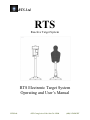
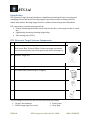
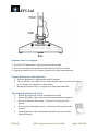
RTS Ltd. RTS Reactive Target System RTS Electronic Target System Operating and User’s Manual RTS Ltd. 4152 Georgia Ave Palo Alto CA 94306 (408) 9-TARGET RTS Ltd. Introduction RTS (Reactive Target System) introduces a significant technological leap in erecting and managing wireless electronic shooting ranges. It provides accurate counting of hits in indoor and outdoor shooting ranges, both for combat trainees and private individuals. RTS represents a revolutionary approach in: Totally eliminating the need to move from the fire line to the target in order to check hits Significantly increasing shooting range safety Time saving (up to 50%). RTS Electronic Target Systems Components: Qty Description Illustration 9 Self-sealing Reactive Target Torso in a choice of 6 colors: Black, Red, Green, Blue, Yellow & White. Each torso target can absorb several thousand hits (even from point zero) before wearing out 10 Reactive Target Poll 10 Reactive Target Base 1 RTS Numerator (controls up to 9 targets) 2 RTS Remote-control 9 RTS Transmitter + RTS Sensors The following accessories are not included and can be purchased. Target’s disc numbers Plastic image bags (for torsos) RTS Ltd. Smart Joints Carry bags 4152 Georgia Ave Palo Alto CA 94306 (408) 9-TARGET RTS Ltd. RTS Enumerator Setup 1. Open lid at the back of the monitor and insert 6 AA batteries as indicated and close the lid. 2. Position the monitor close to the firing line. 3. Push up the left switch on monitor until the indicator S-29 blinks for one second. 4. Push down the right switch on the monitor until LN (Learn) lights up 5. Wait until the message ER light up, which indicates that all previous records were erased. Transmitter and Sensor Setup 1. Place RTS Target Base on the ground, making sure it is stable, with captions facing the firing line. 2. Place the trunk of the target into the appropriate socket on the base and attach the target torso to the upper part of the column. You can also place the bottom push the column into a joint and then push it into the joint round socket in the base (for a nock over target) 3. Use the rubber band which is included, or any other adhesive tape, to attach the sensor disc to the target column, about 2 inches above base, facing the firing line. 4. Connect the sensor’s wire to the transmitter and make sure that it is properly connected. The transmitter’s switch has 3 positions: Middle: normal sensitivity. Left: high sensitivity. Right : low sensitivity. Insert transmitter into its socket in the base – aerial pointed up. 5. Repeat for additional targets (up to 9 targets). RTS Ltd. 4152 Georgia Ave Palo Alto CA 94306 (408) 9-TARGET RTS Ltd. Remote control congruity 1. Press the RTS Numerator’s right button until LN is visible. 2. Press several times on any remote control button until R-1 is visible 3. Repeat procedure for up to 3 remote controls to be used simultaneously Target/Numerator Coordination 1. Press the Numerator’s right switch until LN appears 2. Hit the RTS Reactive Target Torso with a metallic object or shoot one bullet at it. T1 (Target No.1) appears on the monitor. 3. Repeat procedure for up to 9 targets to be used simultaneously . Operating the Remote Control 1. 2. 3. 4. 5. Button #1 (upper left corner) turns Monitor On/Off Button #2 (upper right corner) rolls the target numbers forwards Button #3 (bottom left corner) – erases score of target on the display. Button #4 (bottom right corner) – rolls back to the targets on the monitor. Pressing buttons 1 and 3 simultaneously will erase score on the displayed target. RTS Ltd. 4152 Georgia Ave Palo Alto CA 94306 (408) 9-TARGET RTS Ltd. Trouble Shooting Part Numerator Problem Does not turn on: Resolution Check that the batteries are correctly inserted. Check that the batteries are fully charged and change if necessary. Numerator Incorrect scoring: Check the transmitter’s range limit. Try to raise the transmitter’s elevation from the ground. Replace batteries. Sensor & Transmitter No signal: Insert batteries. Check connection sensor/transmitter. Check if sensor is intact. Change sensor Sensor & Transmitter Transmitter Sensitivity Start by placing selector sensitivity switch on default (middle position). In case of low score: move sensitivity switch away from the green connector to increase sensitivity In case of over score: move sensitivity switch towards the green connector to decrease sensitivity Specifications: All system components can be easily mobilized. Effective distance from target to monitor up to 200 meters depending on the conditions of the area. Range can be increased by raising the transmitter higher up from ground level. Closest effective firing range: 5 meters for pistol, 10 meters for rifle Firing from a closer range can cause over score in a near target due to the blast. RTS Ltd. 4152 Georgia Ave Palo Alto CA 94306 (408) 9-TARGET


![AISER [USER MANUAL OF AISER] - Internet Banking](http://vs1.manualzilla.com/store/data/005712358_1-d8e4e34a51ac40b22276b6e3d3c9bbc0-150x150.png)