1
User Manual
ODM-300
ODM-300
FOREWORD
We congratulate you on your choice of digital satellite tv receiver. The ODM300 is
manufactured in Scotland, UK by RSD Communications Ltd. to very high standards
and is continually upgraded with new software. Please consult your dealer or the
RSD WWW site at http://www.rsd-communications.co.uk for the latest details.
SAFETY INSTRUCTIONS
Place your satellite receiver on a protected, dry and well ventilated spot. Never put
anything on top of the satellite receiver as this prevents the necessary ventilation.
The satellite receiver contains sensitive, hazardous parts and should therefore be
placed away from childrens reach and so that it cannot fall down. Clean the exterior
of your satellite receiver with a dry and soft cloth. Never let any form of liquid
come into contact with the receiver as this can damge the components and destroy
the receiver. Never use abrasive materials to clean the receiver as this will damage
the receiver finish.
CONTENTS
2,
Foreword, Safety, Mains Connection, Enclosed Parts.
3,
Front/Back Panel Description.
4,
Remote Control Handset Description & Functions.
5,
Connector Pin Out Details.
6,
Connection Diagram.
7,
Installation Connect Up Details.
8,
LNB Setup.
9,
Automatic Channel & Network Search.
10,
Manual Channel Input & Edit.
11/12,
Menu Flow Chart.
13,
Edit Name, Line Up, Parental Control & Time.
14,
Receiver Settings.
15,
Technical Specification.
WARNING !!!
Never remove the receiver cover - risk of electric shock!.
MAINS LEAD CONNECTION
The satellite receiver should be connected directly to the mains outlet socket. The
use of a mains extension lead is not recommended.
ENCLOSED PARTS
The following parts are enclosed:
ODM300 satellite receiver.
Remote control handset.
Two LR3 (AAA) batteries.
Coaxial cable (UHF connection).
User manual.
Digital "Free To Air" Receiver
2
USER MANUAL ODM-300
USER MANUAL ODM-300
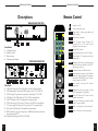
Descriptions
Remote Control
ODM300 RECEIVER FRONT VIEW
Stand-by (on/off).
Digital
Turns the sound off and on.
09
AUDIO
DPA
1
3
2
4
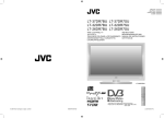
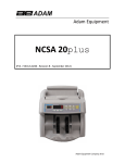
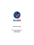
Front Panel:
1. Channel up/down.
2. Standby (on/off).
3. Remote sensor.
4. Channel readout display.
TEXT
Change between teletext, mix & TV picture.
OK
9
Confirm selection in the DPA & menu's.
Selects alternative settings on the different
menu lines. Adjust volume level. Programme
information NOW/NEXT. Move forward/
backward pages in the "DPA".
10
STORE
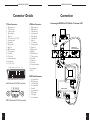
Rear Panel:
1. LNB/dish connection.The coaxial cable to the dish is connected here.
2. UHF channel adjust. To tune the UHF output to the TV or VCR (30-45).
3. UHF test signal. To generate a test pattern to aid tuning of TV or VCR.
4. UHF Output. The UHF lead to the TV or VCR is connected here.
5. UHF TV antenna in. The TV antenna lead is connected here.
6. VCR scart (see page 5 for pin out). The scart to the VCR is connected here.
7. TV scart (see page 5 for pin out). The scart to the TV is connected here.
8. Hi-Fi audio out left & right. For amplifier or home cinema.
9. RS232 connector (see page 5 for pin out). An RS232 cable can be connected
between here and a P.C.
10. Mains lead. Mains input 95-250V AC 50/60Hz.
3
Switch between TV channel mode & radio
channel mode.
Channel up/down. Move up/down the menu
lines. Move between channels in the "DPA".
Teletext page up/down.
LN B
8
Direct Program Access, Displays TV
programme list in TV mode & radio
programme list in radio mode.
Select MENU function.
RADIO
7
Change audio soundtrack.
MENU
ODM300 RECEIVER REAR VIEW
1 2 3 4 5 6
Select channel, teletext page numbers and
MENU settings.
TIME
DELETE
SAT/CANCEL
VIDEO
TV
3
Store settings in the menu's & channel
organisation.
Display time & date in top right of screen
(only if transmitted by broadcaster).
Delete TV channels in TV mode & radio
channels in radio mode.
Cancel out of menu pages. Switch to satellite
picture (if scart connected).
Switch to video picture (if scart connected).
Switch to TV picture (if scart connected).
4
USER MANUAL ODM-300
USER MANUAL ODM-300
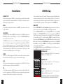
Connector Details
Connection
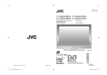
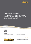
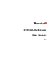
TV Scart Connector:
1. Right audio out.
3. Left audio out.
4. Audio ground.
5. Blue ground.
7. Blue out.
8. AV status out (0/5/12V).
9. Green ground.
11. Green out.
13. Red ground.
15. Red out.
16. RGB status out.
17. Video ground.
18. Ground.
19. Video out.
21. Ground (chassis).
VCR Scart Connector:
1. Right audio out.
2. Right audio in.
3. Left audio out.
4. Audio ground.
5. Blue ground.
6. Left audio in.
7. Blue in.
8. AV status in.
9. Green ground.
11. Green in.
13. Red ground.
15. Red in.
16. RGB status in.
17. Video ground.
18. Ground.
19. Video out.
20 Video in.
21. Ground (chassis).
No connection:
2, 6, 10, 12, 14, 20
20 18 16 14 12
10 8
21 19 17 15 13 11
9
6
7
4
5
1
Scart Connector Pin Out (rear view)
12345
6789
O DM300 DIG ITAL
SAT ELL ITE RECEIV ER
LNB
TV
No connection:
10, 12, 14
2
3
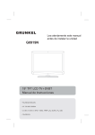
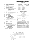
Connecting the ODM300 to TV, VCR, dish, TV antenna, & P.C.
RS232 Serial Connector:
1. No connection.
2. RX data input.
3. TX data output.
4. No connection.
5. Ground.
6. No connection.
7. RTS output.
8. CTS input.
9. No connection.
VIDE O RECO RDE R
TV
OU T
ANT
IN
RS232 Connector Pin Out (rear view)
5
6
USER MANUAL ODM-300
USER MANUAL ODM-300
Installation
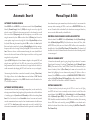
LNB Setup
CONNECT UP
Before connecting up the ODM300 it is essential that your satellite dish is installed
as per the manufacturers recommendations. The ODM300 is connected as per the
diagram on page 6 and as follows.
The local oscillator settings (LO) for the LNB's connected to the ODM300 must be
set before channel search can be carried out. Many LNB's have 2 LO which are
switched between by a 22Khz tone signal from the ODM300. For frequencies over
11.699 the ODM300 will generate a 22Khz signal and select the HIGH LO.
DISH
Your satellite dish should be connected to the LNB "f" type connector on the rear
of the ODM300.
LNB SETUP
From the MAIN MENU select 4 (Installation) using the numeric keys (direct) or
arrow keys up/down (navigation) then OK to pick highlighted selection.
From the INSTALLATION menu select 1 (Install LNB). Then select 1 (LNB
Settings). In the LNB SETTINGS menu you can change between LNB 1-32
using the arrow keys right/left when option 1 is highlighted. Pick the LNB number
you would like to edit. This would normally be LNB 1 for a single LNB setup.
Select option 2 (LOW Band) and key in the LOW LO using the numeric keys and
OK to confirm. Select option 3 (HIGH Band) if appropriate and key in the HIGH
LO and OK to confirm. Press STORE to save LNB changes. Press SAT/CANCEL
to move back out of the MENU's
In the INSTALL LNB menu option 2 (LNB Power) allows the LNB power to be
switched Off for connection with an analogue receiver.
LNB SETTINGS
UNIVERSAL LNB
Settings for Universal type LNB with 2 x LO connected to
- ODM300 with no DiSEqC switch.
UHF AERIAL
Connect your UHF aerial to ANT IN on the back of the ODM300. Connect the
TV OUT on the back of the ODM300 to your VCR or TV ANT IN/RF IN with
the enclosed UHF coaxial cable.
The TEST switch on the rear of the ODM300 can be used to aid UHF tuning. Put
this to the ON position (upper) and a test signal will be transmitted by the ODM300.
Select an unused programme on your TV and tune the TV until black and white
bars are visible. The same can be done to tune the ODM300 to your VCR. The
UHF channel from the ODM300 can be tuned between 30-45 using a small
screwdriver in the CH adjustment on the back panel.
SCART
If your TV or VCR is equipped with SCART connectors then we would recommend
that you connect up using these to improve picture and audio quality.
HI-FI
Hi-fi or home cinema equipment can be connected to the AUDIO OUT left and
right RCA connector on the back of the ODM300.
1
LNB
1
2
LOW Band
9.750
3
HIGH Band
10.600
4
DiSEqC
5
22Khz
-
Help Text
TIME
LNB SETTINGS
1
LNB
2
LOW Band
3
HIGH Band
4
DiSEqC
5
22Khz
2
10.750
D1
Help Text
P.C.
A PC can be connected to the RS232 connector on the back of the ODM300. This
is used for upgrading the ODM300 with the latest software allowing enhanced
features etc. Please consult your dealer for the latest details.
TIME
LNB SETTINGS
1
LNB
2
LOW Band
3
HIGH Band
4
DiSEqC
5
22Khz
Help Text
C-BAND LNB
Settings for C-Band LNB with LO of 5.150 connected to
-K 9ODM300 with DiSEqC switch on D2
3
5.150
-
D2
TIME
7
STANDARD LNB
Settings for LNB with single LO of 10.750 connected to
ODM300 with DiSEqC switch on D1
NOTE IF NO DISEQC SWITCH IS CONNECTED TO THE ODM300
THE SETTINGS OF OPTION 4 & 5 WILL HAVE NO EFFECT.
8
USER MANUAL ODM-300
USER MANUAL ODM-300
Automatic Search
Manual Input & Edit
AUTOMATIC CHANNEL SEARCH
Select MENU with the MENU key on the remote control. Select 4 (Installation).
Select 4 (Channel Setup). Select 1 (LNB) and using the arrow keys right/left
select the correct LNB that has been setup previously for the channels you would
like to scan. Select 2 (Frequency) and enter the frequency you would like to scan
using the numeric keys then OK to confirm. Select 3 (Polarity) and choose the
K 17
correct polarity using the arrow keys right/left. Select 4 (Symbol Rate) and enter
the Symbol Rate using the numeric keypad and OK to confirm. An Auto Symbol
Rate search can be carried out by selecting 4 (Symbol Rate) and before entering a
frequency with the box showing 5 dashes pressing OK. The box would now show
Auto. Please note that we would recommend entering the correct Symbol Rate if
known as the Auto search feature will take longer to search due to the large search
range that has to be perfomed.
Option 5 (FEC Code) can be left set to Auto or changed to the required FEC code
using the arrow right/left keys. If the FEC code is not on Auto and the FEC rate
being transmitted is not the same as that selected , the signal will not be locked (we
would recommend only changing the FEC code from Auto on very weak signals).
Some channels may require manual entry either because they do not transmit the
necessary tables containing the PID's or are shown as ENCRYPTED when they
are not. Channels which are described by the broadcaster as encrypted when they
are not must be added manually as detailed below.
After entering the details above a search can be started by selecting 7 (Start Scan).
The display will now show the Start Scan screen and indicate if FEC Lock &
QPSK Lock have been achieved. Any NEW channels found will be added to the
TV or RADIO channel list.
AUTOMATIC NETWORK SEARCH
An automatic network search (scan multiple transponders) can be carried out by
selecting a scanned channel and going through the procedure above with the addition
of switching option 6 (Auto Scan All Channels) to On before selecting Start
Scan. If the Auto Scan box shows Unavailable then no Auto scan can be carried
out as the transmission does not carry the Auto Scan information in the table known
as the NIT. The Auto Scan multiple transponders can only be enabled if the
information is transmitted by the broadcaster and the option can be switched to On.
9
DECODING CLEAR CHANNEL'S SHOWN AS ENCRYPTED
Select the channel. Press MENU. Select 4 (Installation). Select 4 (Channel Setup).
Select 8 (Manually Input PID's). Verify that there are values in the Video, Audio
& PCR PID boxes (if they are set to 0 then the PID's will have to be set manually as
detailed below). Select 6 (Add This Channel To Channel List). The channel will
be added to the end of the channel list and will now decode when selected provided
it is not encrypted.
MANUAL CHANNEL INPUT
A channel can be manually input by going through the procedure for Automatic
Channel search but instead of selecting 7 (Start Scan) select 8 (Manually Input
PID's). Then enter the Video, Audio, PCR & Teletext PID in decimal form (hex
shown in brackets). Select 5 (New Name) and a name can be entered for the
channel by highlighting the new character and pressing OK (delete to delete a
character). Press STORE to move back to the MANUALLY INPUT PID's MENU
and press 6 (Add This Channel To Channel List) to add to channel list. A channel
with no Video PID will be added to the RADIO channel list.
EDITING CHANNEL PID'S
This feature should only be used after ensuring that the PID's to be entered are valid. Typing
invalid PID's will cause the receiver to continually reset when the channel is selected. Choose the
required channel. Select MENU. Select 4 (Installation). Select 4 (Channel Setup).
Select 8 (Manually Input PID's). The various PID's can now be edited. The
PID's should be entered in decimal form (HEX shown in brackets). After entering
the new PID's these can be stored by pressing STORE or a new channel can be
added to the channel list with these values by selecting 6 (Add This Channel To
The Channel List).
10
USER MANUAL ODM-300
USER MANUAL ODM-300
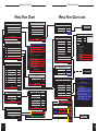
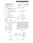
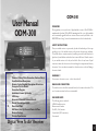
Menu Flow Chart
PARENTAL CONTROL
MAIN MENU
1
2
3
4
Menu Flow Chart cont.
1
Parental Control
Information
Organise Channels
Installation
No Parental Block
2
Block 12
3
Block 16
4
Block All
5
Help Text
Receiver Setup
3
Time
4
Channel Setup
5
Change Install PIN
CHANNEL SETUP
Help Text
TIME
Help Text
TIME
RECEIVER SETUP
1
EIT Display Time
10 secs
2
Scart Output Mode
PAL
RGB Output
Off
4
Screen Format
4:3
5
Auto Update Channels
Off
6
Receiver Language
English
3
7 Soundtrack Language
8
English
Subtitle Language
Help Text
1
2
3
4
5
6
7
8
9
10
LNB Settings
1
LNB Power
On
Help Text
TIME
Signal Detection
2
Decoder Information
Help
Help Text
Text
11
POOR
GOOD
Polarity
Horizontal
1
Canal+ GUL
Symbol Rate
27500
2
Canal+ Swe
5
FEC Code
Auto
3
Canal+ Fin
4
Canal+ Nor
5
Canal+ Dan
6
Hallmark
7
Nelonen
Travel
Version V00.2D
TVBS
6
Auto Scan All Channels
CNN International
7
Start Scan
Canal+ GUL
8
Unavailable
Manually Input PID’s
Canal+ Swe
Help Text
TIME
Canal+ Den
Canal+ Fin
CHANGE PIN
Canal+ Nor
Help text
1
New PIN
2
Confirm New Pin
-------
1
2
Local Time Offset
GMT
Transmitted Time Offset
Help Text
TIME
MANUALLY INPUT PID’S
New Name
1
Video PID
512 (0200)
Canal+ GUL
2
Audio PID
650 (028A)
3
PCR PID
8190 (1FFE)
4
Teletext PID
576 (0240)
5
6
1
LNB
2
LOW Band
9.750
3
HIGH Band
10.600
4
DiSEqC
5
22Khz
1
--
New Name
Canal+ GUL
Add This Channel To The Channel List
Help Text
TIME
! “ # ¤ %& ` ( ) * + , - , /
0 1 2 3 4 5 6 7 8 9 : ; < = >?
@ A B C D E F G H I J K L MN O
P Q R S T UV WX Y Z [ \ ] ^ _
` a b c d e f g h i j k l mn o
p q r s t u v wxyz { | } ~
Decoder Information
Bootrom
Checksum xxxxxxxx
Version V01.00
Flash
Checksum xxxxxxxx
Version V00.2D
Program
Checksum xxxxxxxx
Version V01.00
Firmware
Checksum xxxxxxxx
BootCode Ver1.0
TIME
Astra Satellite Network 19.2 E
POOR
SAVING
TIME
TIME
Signal
Signal
4
Help Text
TIME
10.10
11.836
Yes
3
INFORMATION
1
1
Frequency
7/8
QPSK Lock
Cartoon Network
LNB SETTINGS
2
LNB
2
TIME
1
1
FEC Lock
TNT
Off
INSTALL LNB
Confirm New Pin
Start Scan
Organise Video Channels
2
2
SAVING
-------
TIME
INSTALLATION
Install LNB
New PIN
Change Parental Pin
TIME
1
CHANGE PIN
1
22 February 1998
GOOD
Version V02.09
SAVING
09 February 1998
12
USER MANUAL ODM-300
USER MANUAL ODM-300
Editing Name, Line Up etc.
Receiver Settings
EDITING CHANNEL NAME
Choose the required channel. Select MENU. Select 4 (Installation). Select 4
(Channel Setup). Select 8 ( Manually Input PID's). Select 5 (New Name). In
the New Name MENU the name can be edited by highlighting the new character
and presssing OK. A character can be deleted by pressing DELETE. When the
name is correct press STORE, you will now move back to the MANUALLY
INPUT PID's screen. Pressing STORE again will update the channel name of the
present channel. Pressing 6 (Add This Channel To The Channel List) will add a
new channel to the channel list with the new name and other settings.
RECEIVER
SETTINGS
Message
Cause
Action
Select MENU. Select 4 (Installation). Select 2 (Receiver Setup).
Option 1 adjusts the length of time the programme information is displayed on the
screen after channel change. This can be adjusted between Off and 31 seconds.
Option 2 changes the video output mode between PAL, NTSC & Auto (Auto will
output PAL when decoding PAL and NTSC when decoding NTSC).
Option 3 switches RGB Output On or Off.
Option 4 changes screen format between 4:3 & 16:9 (only if widescreen transmission).
Option 5 when Off if channel PID's are changed by user to incorrect values these
will not be automatically updated by the receiver, when new channels or deleted
channels are found these will not be added to channel list. When On new channels
or deleted channels found will be added to channel list and PID's will be changed
automatically if these have been modified by user to incorrect values.
Option 6 sets the receiver MENU language.
Option 7 sets default Soundtrack Language.
Option 8 sets Subtitle Language or switches subtitles Off.
Press STORE to save any changes.
SORTING CHANNEL LINE UP
The channel line up can be organised to suit your requirements. When in TV mode
the TV channels will be organised and when in RADIO (press RADIO to change
between TV/RADIO) mode the RADIO channels will be organised. Select MENU.
Select 3 (Organise Channels). Highlight the required channel using the arrow
keys, press OK to "lift", move to new position and press OK to "drop". A channel
can be deleted by highlighting, pressing DELETE then DELETE to confirm.
Press STORE to save changes.
PARENTAL CONTROL
Parental control can be switched ON to prevent unauthorised viewing. Select MENU.
Select 1 (Parental Control). Highlight required option and press OK then STORE
to save change. Block 12 & Block 16 will only operate if the broadcaster transmits
the correct viewing age details with the programme.
TIME SETTING
Select MENU. Select 4 (Installation). Select 3 (Time). Tick option 2 to have the
time set by the broadcaster over the air or don't tick this option and set the time by
highlighting option 1 then use the arrow keys right/left to change +/- GMT until
the correct time is displayed at the bottom of the MENU. Press STORE to save
new settings before exiting.
13
CHANGE PARENTAL & INSTALLATION PIN's
Select MENU. Select either 1 (Parental Control) or 4 (Installation) depending
which PIN you would like to change. Select 5 (Change PIN). Key in new PIN
then key in again to confirm. The Parental & Installation PIN is factory set to 0000
which disables the PIN feature. Setting to any other value sets the PIN active.
Factory default PIN is 3259 which will always work in the event that you
loose your PIN.
FACTORY RESET
A factory reset sets receiver to default values and all stored channels are lost.
Select MENU. Select 3 (Organise Channels). Simultaneously press channel up/
down on the receiver front panel. You will be prompted to press OK to confirm
factory reset. Press OK on handset to perform factory reset.
14
USER MANUAL ODM-300
USER MANUAL ODM-300
Technical Specification
General
Number of Channels
Front panel
Power
Power consumption maximum
Dimensions
Weight
Connections
TV
VCR
Modulator
Antenna
Audio
Serial
Tuner
Frequency range
Type
Tuner I.F.
LNB control
Demodulator
System
Decoding (Video)
Audio
Control
Video
Audio
999 SCPC & MCPC
Channel up/down
Standby
IR sensor
3 Digit LED channel number display
95-250V AC 50/60Hz.
40W
W=340mm, D=256mm, H=67mm
2 kg
SCART (video, L/R audio & RGB out)
SCART (video, L/R audio out &
video/RGB/audio loop through)
PAL I, channel 30-45, 77dBuV typical
F type, 14/18V (400mA max.)& 22kHz
2 RCA phono L/R audio connectors
RS232 serial connector.
RSD
Communications Ltd.
A company with vision since
our launch in 1987, RSD today is a leading force in the
design and manufacture of
satellite tv equipment.
950 - 2150 MHz
Single input "F" connector.
479.5 MHz
14/18V(400mA max)22kHz & DiSEqC
2-45 Msps@ 1, 1/2, 3/4, 5/6, 7/8 FEC
Suitable for SCPC & MCPC data rates.
ISO13818 (MPEG-2) MP@ML,
NTSC & PAL
22.05,32,44.1 & 48kHz sample rates.
Motorola "Coldfire" @ 33MHz, 512k
RAM & 512K flash memory
Output 1V p-p, 75Ohm
Output 500mV rms, 600Ohm
RSD Communications Ltd.
Unit 9, 5 Munro Road, Springkerse Industrial Estate, Stirling, FK7 7UU, Scotland, UK
Tel: +44 (0) 1786 450572 Fax: +44 (0) 1786 474653
WWW http://www.rsd-communications.co.uk EMAIL [email protected]
15