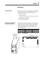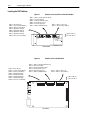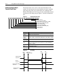
1
Allen-Bradley
Bulletin 1203
Remote I/O
Communications
Module
Cat. Nos. 1203-GD1,
1203-GK1, or 1336-GM1
Firmware 1.xx – 4.xx
User Manual
Important User Information
Because of the variety of uses for the products described in this
publication, those responsible for the application and use of this
control equipment must satisfy themselves that all necessary steps
have been taken to assure that each application and use meets all
performance and safety requirements, including any applicable laws,
regulations, codes and standards.
The illustrations, charts, sample programs and layout examples
shown in this guide are intended solely for purposes of example.
Since there are many variables and requirements associated with any
particular installation, Rockwell Automation does not assume
responsibility or liability (to include intellectual property liability) for
actual use based upon the examples shown in this publication.
Rockwell Automation publication SGI-1.1, Safety Guidelines for the
Application, Installation, and Maintenance of Solid-State Control
(available from your local Rockwell Automation office or online at
www.ab.com/manuals/gi), describes some important differences
between solid-state equipment and electromechanical devices that
should be taken into consideration when applying products such as
those described in this publication.
Reproduction of the contents of this copyrighted publication, in
whole or in part, without written permission of Rockwell
Automation, is prohibited.
Throughout this manual we use notes to make you aware of safety
considerations:
!
ATTENTION: Identifies information about practices
or circumstances that can lead to personal injury or
death, property damage or economic loss.
Attention statements help you to:
•
Identify a hazard.
•
Avoid the hazard.
•
Recognize the consequences.
Important: Identifies information that is critical for successful
application and understanding of the product.
Summary of Changes
The information below summarizes the changes made to this manual
since the last release.
Updated Information
This manual incorporates the information found in the following two
manuals:
• Bulletin 1203 Remote I/O Communication Module Getting
Started Manual, Publication 1203-5.1.
•
Bulletin 1203 Remote I/O Communications Module Reference
Manual, Publication 1203-5.0.
It also contains new information.
Updates and Additions
The information below summarizes the changes to this manual since
its last release:
Page
2-5
Description
Important statement added:
2-6
Injury or equipment damage can result from loss of PLC or Controller Logic
Commands (Stop, Start, etc.) when all these conditions are true:
- module firmware 3.04 or lower.
- 230.4k baud rate.
- block transfer is enabled (DIP switch SW3-1 is ON).
- block transfers to the module are used (in the ladder program or by DriveTools/
DriveTools32 using a Remote I/O pass thru connection).
Do not use the 230.4k baud rate if you are using a module with 3.04 or earlier
firmware and your program uses block transfers. Use the 57.6k or 115.2k baud
rate instead.
Attention statement added:
Due to an anomaly in firmware release 4.01, Remote I/O modules that are used
only for block transfer messages require the following configuration: switches for
block transfer and reference/feedback should both be enabled (SW 3.1 and SW
3.3 are ON. SW 3.2 and SW 3.4 through 3.8 are OFF).
This configuration prevents a fault on power up. It does not affect rack I/O
allocation or the ladder logic program because it still fits within 1/4 rack I/O space.
The drive will, however, generate a serial fault if the communications module is
disconnected or loses power.
2
End of Summary of Changes
Table of Contents
Preface
Using This Manual
Preface Objectives . . . . . . . . . . . . . . . . . . . . . . . . . . . . . . . . . . . . . . . . . .
Audience for This Manual . . . . . . . . . . . . . . . . . . . . . . . . . . . . . . . . . . . . .
Purpose of This Manual . . . . . . . . . . . . . . . . . . . . . . . . . . . . . . . . . . . . . .
Firmware Support . . . . . . . . . . . . . . . . . . . . . . . . . . . . . . . . . . . . . . . . . . .
Terms and Abbreviations. . . . . . . . . . . . . . . . . . . . . . . . . . . . . . . . . . . . . .
Safety Precautions . . . . . . . . . . . . . . . . . . . . . . . . . . . . . . . . . . . . . . . . . .
Rockwell Automation Support. . . . . . . . . . . . . . . . . . . . . . . . . . . . . . . . . .
P-1
P-1
P-1
P-1
P-2
P-3
P-4
Chapter 1
Overview
Chapter Objectives . . . . . . . . . . . . . . . . . . . . . . . . . . . . . . . . . . . . . . . . . .
Description of the Remote I/O Communications Modules . . . . . . . . . . . .
Features of the Communications Module . . . . . . . . . . . . . . . . . . . . . . . . .
Compatibility . . . . . . . . . . . . . . . . . . . . . . . . . . . . . . . . . . . . . . . . . . . . . . .
Hardware Description . . . . . . . . . . . . . . . . . . . . . . . . . . . . . . . . . . . . . . . .
Required Tools and Equipment. . . . . . . . . . . . . . . . . . . . . . . . . . . . . . . . .
Overview of Setting Up the Module . . . . . . . . . . . . . . . . . . . . . . . . . . . . .
1-1
1-1
1-2
1-3
1-4
1-6
1-6
Chapter 2
Configuring the Module
Chapter Objectives . . . . . . . . . . . . . . . . . . . . . . . . . . . . . . . . . . . . . . . . . . 2-1
Safety Precautions and Important Information . . . . . . . . . . . . . . . . . . . . . 2-1
Locating the DIP Switches . . . . . . . . . . . . . . . . . . . . . . . . . . . . . . . . . . . . 2-2
Factory-Default Settings . . . . . . . . . . . . . . . . . . . . . . . . . . . . . . . . . . . . . . 2-3
Quick Configuration . . . . . . . . . . . . . . . . . . . . . . . . . . . . . . . . . . . . . . . . . 2-3
Configuring the module. . . . . . . . . . . . . . . . . . . . . . . . . . . . . . . . . . . . . . . 2-4
Setting Switches on SW3 . . . . . . . . . . . . . . . . . . . . . . . . . . . . . . . . . . . . . 2-5
Setting Switches on SW2 . . . . . . . . . . . . . . . . . . . . . . . . . . . . . . . . . . . . . 2-8
Setting Switches on SW1 . . . . . . . . . . . . . . . . . . . . . . . . . . . . . . . . . . . . 2-12
Chapter 3
Installing the Module
Chapter Objectives . . . . . . . . . . . . . . . . . . . . . . . . . . . . . . . . . . . . . . . . . .
Selecting Cables . . . . . . . . . . . . . . . . . . . . . . . . . . . . . . . . . . . . . . . . . . . .
Selecting a Termination Resistor . . . . . . . . . . . . . . . . . . . . . . . . . . . . . . .
Installing a 1203-GD1 or 1203-GK1 Module. . . . . . . . . . . . . . . . . . . . . . .
Installing a 1336-GM1 Board . . . . . . . . . . . . . . . . . . . . . . . . . . . . . . . . . .
3-1
3-1
3-2
3-3
3-6
Chapter 4
Creating Ladder Logic
Programs
Chapter Objectives . . . . . . . . . . . . . . . . . . . . . . . . . . . . . . . . . . . . . . . . . . 4-1
Understanding the I/O Image Table . . . . . . . . . . . . . . . . . . . . . . . . . . . . . 4-1
Control Features . . . . . . . . . . . . . . . . . . . . . . . . . . . . . . . . . . . . . . . . . . . . 4-2
Datalinks . . . . . . . . . . . . . . . . . . . . . . . . . . . . . . . . . . . . . . . . . . . . . . . . . . 4-2
Settings for the Ladder Logic Program Examples. . . . . . . . . . . . . . . . . . . 4-5
Example PLC Ladder Logic Program . . . . . . . . . . . . . . . . . . . . . . . . . . . . 4-8
Example SLC Ladder Logic Program . . . . . . . . . . . . . . . . . . . . . . . . . . . 4-10
Example Logix5550 Ladder Logic Program . . . . . . . . . . . . . . . . . . . . . . 4-12
ii
Table of Contents
Chapter 5
Using Block Transfer Messages
Chapter Objectives. . . . . . . . . . . . . . . . . . . . . . . . . . . . . . . . . . . . . . . . . . . 5-1
Understanding Block Transfer . . . . . . . . . . . . . . . . . . . . . . . . . . . . . . . . . . 5-1
Understanding the Block Transfer Status Word . . . . . . . . . . . . . . . . . . . . . 5-2
Understanding Data Storage . . . . . . . . . . . . . . . . . . . . . . . . . . . . . . . . . . . 5-3
Example PLC Block Transfers . . . . . . . . . . . . . . . . . . . . . . . . . . . . . . . . . . 5-3
Example SLC Block Transfers . . . . . . . . . . . . . . . . . . . . . . . . . . . . . . . . . . 5-5
Example Logix5550 Block Transfers . . . . . . . . . . . . . . . . . . . . . . . . . . . . . 5-7
Notes Regarding Block Transfer Programming . . . . . . . . . . . . . . . . . . . . . 5-8
Chapter 6
Troubleshooting
Chapter Objectives. . . . . . . . . . . . . . . . . . . . . . . . . . . . . . . . . . . . . . . . . . . 6-1
LEDs on the Remote I/O Communications Module . . . . . . . . . . . . . . . . . . 6-1
FAULT LED. . . . . . . . . . . . . . . . . . . . . . . . . . . . . . . . . . . . . . . . . . . . . . . . . 6-2
SCANport STS LED. . . . . . . . . . . . . . . . . . . . . . . . . . . . . . . . . . . . . . . . . . 6-2
Health LED. . . . . . . . . . . . . . . . . . . . . . . . . . . . . . . . . . . . . . . . . . . . . . . . . 6-2
Rem I/O ACT LED . . . . . . . . . . . . . . . . . . . . . . . . . . . . . . . . . . . . . . . . . . . 6-2
Rem I/O STS LED . . . . . . . . . . . . . . . . . . . . . . . . . . . . . . . . . . . . . . . . . . . 6-2
Appendix A
Specifications
Appendix Objectives . . . . . . . . . . . . . . . . . . . . . . . . . . . . . . . . . . . . . . . .
1336-GM1 Board Specifications . . . . . . . . . . . . . . . . . . . . . . . . . . . . . . .
1203-GD1 Module Specifications. . . . . . . . . . . . . . . . . . . . . . . . . . . . . . .
1203-GK1 Module Specifications. . . . . . . . . . . . . . . . . . . . . . . . . . . . . . .
A-1
A-1
A-2
A-2
Appendix B
Supported Block Transfer
Messages
Appendix Objectives . . . . . . . . . . . . . . . . . . . . . . . . . . . . . . . . . . . . . . . . B-1
Supported Block Transfer Messages . . . . . . . . . . . . . . . . . . . . . . . . . . . . B-1
Block Transfer Data Structure . . . . . . . . . . . . . . . . . . . . . . . . . . . . . . . . . B-2
Parameter Value Read . . . . . . . . . . . . . . . . . . . . . . . . . . . . . . . . . . . . . . . B-3
Parameter Value Write . . . . . . . . . . . . . . . . . . . . . . . . . . . . . . . . . . . . . . . B-4
Parameter Read Full . . . . . . . . . . . . . . . . . . . . . . . . . . . . . . . . . . . . . . . . B-5
Product ID Number Read. . . . . . . . . . . . . . . . . . . . . . . . . . . . . . . . . . . . . B-8
Scattered Parameter Value Read. . . . . . . . . . . . . . . . . . . . . . . . . . . . . . B-10
Scattered Parameter Value Write. . . . . . . . . . . . . . . . . . . . . . . . . . . . . . B-12
Continuous Parameter Value Read . . . . . . . . . . . . . . . . . . . . . . . . . . . . B-14
Save/Recall/Initialize . . . . . . . . . . . . . . . . . . . . . . . . . . . . . . . . . . . . . . . B-16
Fault Command Write . . . . . . . . . . . . . . . . . . . . . . . . . . . . . . . . . . . . . . B-17
Fault Queue Entry Read Full . . . . . . . . . . . . . . . . . . . . . . . . . . . . . . . . . B-18
Fault Queue Size Read . . . . . . . . . . . . . . . . . . . . . . . . . . . . . . . . . . . . . B-20
Trip Fault Queue Number Read . . . . . . . . . . . . . . . . . . . . . . . . . . . . . . . B-21
Block Transfer Quick Reference . . . . . . . . . . . . . . . . . . . . . . . . . . . . . . . B-22
Preface
Using This Manual
Preface Objectives
Audience for This Manual
Read this preface to familiarize yourself with the rest of the manual.
In this preface, you will read about the following:
• Intended audience for this manual.
•
Purpose of this manual.
•
Firmware supported by this manual.
•
Terms and abbreviations.
•
Safety precautions.
•
Rockwell Automation support.
Use this manual if you are responsible for setting up and using a
Remote I/O communications module (Bulletin numbers 1203-GD1,
1203-GK1, or 1336-GM1). You must have previous experience with
and a basic understanding of communications terminology,
configuration procedures, required equipment, and safety precautions.
To use this Remote I/O communications module efficiently, you must
be able to program and operate programmable controllers as well as
have a basic understanding of the parameter settings and functions of
the SCANport™ product with which you are communicating.
Purpose of This Manual
This manual is an installation and user guide for the Remote I/O
communications module. The 1203 Remote I/O communications
modules are available for products that include SCANport.
This manual provides the following information:
• An overview of the Remote I/O communications module.
•
Procedures that you need to install, configure, and troubleshoot
the Remote I/O communications module.
•
Example ladder logic programs for controlling a product and
using block transfer messages.
Important: You should read this manual in its entirety before
configuring, installing, operating, or troubleshooting the
Remote I/O communications module.
Firmware Support
This manual supports firmware versions 1.xx to 4.xx (the “xx”
designator may vary). Features that work with specific firmware
versions will be identified.
P–2
Using This Manual
Contents of this Manual
Chapter
Preface
1
2
3
4
5
6
A
B
Title
Using This Manual
Contents
Descriptions of the audience, purpose, background, and scope of this manual.
Overview
Features of the Remote I/O communications
module.
Configuring the Module Procedures for setting DIP switches.
Installing the Module
Procedures for mounting, connecting cables, and
connecting power.
Creating Ladder Logic
Information about addressing, information transPrograms
fer, and sample programs.
Using Block Transfer
Information about messaging and sample proMessages
grams.
Troubleshooting
Information about troubleshooting the module.
Specifications
Environmental, electrical, and communication
specifications.
Supported Block Transfer Information about block transfer messages.
Messages
Related Documentation
You can obtain documentation about Allen-Bradley products,
including PLC controllers, SLC controllers, Logix5550 controllers,
and drives, from your local Rockwell Automation office or
distributor. You can also access documents online at
http://www.ab.com/manuals
Application notes are available at
http://www.ab.com/drives/stddrives/faxback/faxback.htm
Terms and Abbreviations
The following terms are specific to this product. For a complete
listing of automation terminology, refer to the Rockwell Automation
Industrial Automation Glossary, Publication Number AG-7.1.
Terms
Controller
Remote I/O
Remote I/O
Communications
Module
SCANport
SCANport
Peripheral
SCANport
Product
Definition
A solid-state control system that has a user-programmable memory for
storage of instructions to implement specific functions such
as I/O control, logic, timing, counting, report generation, communication, arithmetic, and data file manipulation. A controller is also called a
“programmable logic controller” or “processor.”
I/O connected to a processor across a serial link. With a serial link,
remote I/O can be located long distances from the processor.
This module connects a SCANport product to a Remote I/O link. There
are three types of Remote I/O communications modules: 1203-GD1
module, 1203-GK1 module, and 1336-GM1 board. The Remote I/O
module is also referred to as “adapter,” “module,” and communications
module.”
A standard peripheral communications interface for various
Allen-Bradley drives and power products.
A device that provides an interface between SCANport and a communications system such as Remote I/O. It is often referred to as an
adapter or communications module. For example, the Remote I/O
module is a SCANport peripheral.
A device that uses the SCANport communications interface to communicate with one or more peripheral devices. For example, a motor drive
such as a 1336 PLUS is a SCANport product.
Using This Manual
P–3
Safety Precautions
!
!
!
ATTENTION: Only personnel familiar with SCANport
devices and associated machinery should plan or implement
the installation, start-up, configuration, and subsequent
maintenance of the Remote I/O communications module.
Failure to comply may result in personal injury and/or
equipment damage.
ATTENTION: The 1336-GM1 board contains Electrostatic Discharge (ESD) sensitive parts and assemblies. Static
control precautions are required when handling this assembly. Component damage may result if ESD control procedures are not followed. If you are not familiar with static
control procedures, refer to Allen-Bradley Publication
8000-4.5.2, Guarding Against Electrostatic Damage or any
other applicable ESD protection handbook.
ATTENTION: Injury or equipment damage can result
from loss of PLC or Controller Logic Commands (Stop,
Start, etc.) when all these conditions are true:
•
module firmware 3.04 or lower.
•
230.4k baud rate.
•
block transfer is enabled (DIP switch SW3-1 is ON).
•
block transfers to the module are used (in the ladder
program or by DriveTools/DriveTools32 using a
Remote I/O pass thru connection).
Do not use the 230.4k baud rate if you are using a module
with 3.04 or earlier firmware and your program uses block
transfers. Use the 57.6k or 115.2k baud rate instead.
!
!
ATTENTION: Hazard of equipment damage exists. If
block transfer messages are programmed to frequently
write parameter data, the EEPROM (Non-Volatile Storage)
will quickly exceed its life cycle and cause the product to
malfunction. Do not create a program that frequently uses
block transfer messages to write parameter data to a
product. Datalinks do not write to the EEPROM and should
be used for frequently changed parameters.
ATTENTION: Hazard of equipment damage exits.
Firmware version 3.04 has the following anomaly: If DIP
Switch 2-5 is OFF (No Fault), the product remains in its last
state after a communications loss occurs no matter how DIP
Switch 2-4 is set. If you must use zero data, contact
Rockwell Automation Technical Support.
P–4
Using This Manual
Rockwell Automation Support
Rockwell Automation offers support services worldwide, with more
than 75 sales/support offices, more than 500 authorized distributors,
and more than 250 authorized systems integrators located throughout
the United States alone. In addition, Rockwell Automation
representatives are in every major country in the world.
Local Product Support
Contact your local Rockwell Automation representative for:
•
Sales and order support.
•
Product technical training.
•
Warranty support.
•
Support service agreements.
Technical Product Support
If you need to contact Rockwell Automation for technical assistance,
please call your local Rockwell Automation representative.
Chapter
1
Overview
Chapter Objectives
Chapter 1 provides an overview of the Remote I/O communications
module (1203-GD1 module, 1203-GK1 module, and 1336-GM1
board). In this chapter, you will read about the following:
• Function of the module.
• Features of the module.
• Compatible SCANport products and programmable controllers.
• Parts and hardware of the module.
• Steps for setting up the module.
• Required tools and equipment.
Description of the Remote I/O
Communications Modules
The Remote I/O communications module is an optional interface
designed to provide a direct, digital link between an Allen-Bradley
programmable controller and any one Allen-Bradley SCANport
product. A module is required for each product that you want to
connect to Remote I/O. There are three types of Remote I/O
communications modules:
Catalog Number
1203-GD1
1203-GK1
1336-GM1
Figure 1.1
1203-GD1 Module
and
1203-GK1 Module
Enclosure
NEMA Type 1
NEMA Type 1
Open
Required Power Supply
85 – 264V AC
24V DC +/- 10%
Drive Supplied
Module and Board
1336-GM1 Board
1–2
Overview
The 1203-GD1 and 1203-GK1 modules mount on a DIN rail. They
connect to a SCANport product using a SCANport cable and to the
Remote I/O link using a Remote I/O cable. The 1336-GM1 board
mounts directly onto selected SCANport products. It connects to a
SCANport product using an internal SCANport connector and to the
Remote I/O link using a Remote I/O cable.
Figure 1.2 shows how the modules connect SCANport products to the
Remote I/O link.
Figure 1.2
PLC-5
Remote I/O Link with Remote I/O Communications Modules
1305 Drive
PLUS Drive
SMC
1336GM1
1203-GD1
1203-GK1
Remote I/O Link
Features of the
Communications Module
The 1203-GD1 module, 1203-GK1 module, and 1336-GM1 board let
you connect SCANport products to Remote I/O links and devices.
These modules feature the following:
• DIP switches let you configure how the Remote I/O module
operates before connecting it to the link.
• User-configurable fault action DIP switches let you customize the
module actions when communication errors occur.
• LEDs report link, module, and SCANport product health.
• Datalinks are supported in the module. Datalinks are a SCANport
mechanism for transferring information between a controller and
SCANport device. Each enabled datalink uses two words in the
I/O image table unless it is truncated.
Overview
Compatibility
1–3
SCANport Products
Remote I/O modules are compatible with many SCANport products,
including the following:
Product
1305 AC MICRO Drive➀
1336 IMPACT™ Drive
1336 PLUS AC Drive
1336 PLUS II Drive
1336 FORCE™ Drive
1336 REGEN Line Regeneration Package
1336 SPIDER Drive
1394 AC Mult-Axis Motion Control System
SMC Dialog Plus™
SMP-3 Smart Motor Protector
1397 Digital DC Drive
1557 Medium Voltage Drive
2364F Regenerative DC Bus Supply Unit
Number of
Peripherals
Supported
5
6➁
6➁
6➁
6➁
2
6➁
5
1
2
5
5
6
I/O Words
Minimum
0
0
0
0
0
0
0
0
0
0
0
0
0
Maximum➂
8
8
8
8
8
2➄
8
8
2➄
2➄
8
8
8
Module Use
1203-GD1 or
1203-GK1
Yes
Yes
Yes
Yes
Yes
Yes
Yes
Yes
Yes
Yes
Yes
Yes
Yes
1336-GM1
No
Yes➃
Yes➃
Yes
Yes➃
No
Yes
No
No
No
No
No
No
➀ The Remote I/O modules are compatible with 1305 drives using firmware release 2.xx or greater.
➁ Lower horsepower products may not support a sixth peripheral. To connect multiple peripherals to a SCANport product, a port expander may be required. Refer to
the product user manual to verify that it supports a sixth peripheral.
➂ Many SCANport products support 10 words of I/O (Command/Logic, Speed Reference, and four datalinks). Remote I/O, however, supports only 8 words of I/O.
➃ Drive must be B-frame or larger. If it is a 1336 FORCE drive, it must use a standard adapter board.
➄ Datalinks are not supported by this product.
If you intend to use datalinks to communicate with and control your
SCANport product, verify that your SCANport product supports
datalinks before enabling them in the module.
Controllers
This Remote I/O communications module is compatible with many
programmable controllers, including the following:
• Logix5550
• PLC-2/30® with SD2 (module version 1.02 or later)
• PLC-3®
• PLC Classic Family, including the PLC-5/10 (only with 1771-SN
in Discrete Mode), PLC-5/15™, PLC-5/25™ family
• PLC Enhanced family, including the PLC-5/20™, PLC-5/30,
PLC-5/40™, PLC-5/40L™, PLC-5/60™,
PLC-5/60L™family, PLC-5/80™
• PLC-5/250™
• PLC scanner modules and subscanners
• SLC 500™ with 1747-SN scanner
1–4
Overview
Hardware Description
The hardware included with the module depends on the module that
you have.
1203-GD1 and 1203-GK1 Modules
The 1203-GD1 module and 1203-GK1 module share the same parts.
Figure 1.3 illustrates these parts.
Figure 1.3
Parts of the 1203-GD1 and 1203-GK1 Module
1
3
2
4
6
5
#
1
Part
SCANport Connection
Description
Standard SCANport 8-pin mini-DIN connector for the
SCANport cable.
2
Power Supply Connections Connections for the power supply. Multiple connections allow daisy-chaining.
The 1203-GD1 module uses 85 – 264V AC.
The 1203-GK1 module uses 24V DC.
3
Remote I/O Connection
Standard 3-pin Remote I/O connector.
4
LEDs
Status indicators for the module, SCANport connection, and Remote I/O connection. Refer to Chapter 6.
5
DIP Switches
Switches used to configure the module. Refer to
Chapter 2.
6
DIN Rail Mount
Mount for securely attaching and electrically grounding the module to a DIN rail.
Not Remote I/O connector
One 3-pin connector for connecting the Remote I/O
cable to the module.
Shown
Not Termination Resistors
Two termination resistors for terminating the I/O link at
its physical ends. Refer to Chapter 3.
Shown
Overview
1–5
1336-GM1 Board Hardware
Figure 1.4 illustrates the main parts of a 1336-GM1 board.
Figure 1.4
Parts of the 1336-GM1 Board
4
3
1
2
#
1
2
3
Part
SCANport Connection
Remote I/O Connection
LEDs
4
DIP Switches
Not Kit
Shown
Description
Internal 14-pin female SCANport connector.
Standard 3-pin Remote I/O connector.
Status indicators for the module, SCANport connection,
and Remote I/O connection. Refer to Chapter 6.
Switches used to configure the module. Refer to
Chapter 2.
Materials for mounting the board to the SCANport product. These material include one grounding wrist strap,
four Phillips mounting screws, four stand-off nylon headers, one 3-pin Remote I/O connector, one snap-in comm
housing with mounting instructions, and termination
resistors.
1–6
Overview
Required Tools and Equipment
The tools and equipment required, depend on if you are using a
1203-GD1 module, 1203-GK1 module, or 1336-GM1 board.
1203-GD1 or 1203-GK1 Module
To install and configure a 1203-GD1 module or 1203-GK1 module,
you need the following:
• Remote I/O communications module (1203-GD1 or 1203-GK1).
• 35 x 7.5 mm DIN rail.
• Termination resistor(s).
• Power source.
• 1/8" flathead screwdriver.
• Appropriate cables for SCANport and Remote I/O connections.
Refer to Chapter 3.
• Software such as RSLogix5, RSLogix500, or RSLogix5000 for
programming the controller.
1336-GM1 Board
To install and configure a 1336-GM1 board, you need the following:
• Remote I/O communications board (1336-GM1).
• A kit that includes one grounding wrist strap, four Phillips
mounting screws, four stand-off nylon headers, one 3-pin
connector, and one snap-in comm housing with mounting
instructions (supplied with board).
• #1 Phillips screwdriver.
• Appropriate cable for the Remote I/O connection. Refer to
Chapter 3.
• Software such as RSLogix5, RSLogix500, or RSLogix5000 for
programming the controller.
Overview of Setting Up the
Module
To set up the Remote I/O communications module, you must perform
the following tasks:
1. Read the safety precautions in this manual.
2. Configure the module using the DIP switches. Refer to Chapter 2.
3. Install the module or mount the board. Refer to Chapter 3.
4. Create a ladder logic program to control the SCANport product
(Chapter 4) or send messages to it (Chapter 5).
Chapter
2
Configuring the Module
Chapter Objectives
Chapter 2 provides instructions and information for configuring the
Remote I/O communications module (1203-GD1, 1203-GK1, or
1336-GM1). In this chapter, you will read about the following:
• Factory-default settings.
• Recording the I/O image table.
• Configuring the module.
Important: The communications module is not compatible with
complementary I/O configurations because it uses both
output and input image words for proper product control.
Safety Precautions and
Important Information
Please observe the following safety precautions:
!
!
!
ATTENTION: Hazard of equipment damage exists. When
you make changes to the switch settings, use a blunt, pointed
instrument. Do not use a pencil or pen.
ATTENTION: Hazard of injury or equipment damage
exists. Failure to check connections and switch settings for
compatibility with your application could result in
unintended or undesirable operation. Verify the
configuration is correct for your application.
ATTENTION: Hazard of injury or equipment damage
exists. Unintended or incorrect machine motion can result
from the initial configuration. When a system is configured
for the first time, the motor must be disconnected from the
machine or process during initial system testing.
Important: Due to an anomaly in firmware release 4.01, Remote I/O
modules that are used only for block transfer messages
require the following configuration: switches for block
transfer and reference/feedback should both be enabled
(SW 3.1 and SW 3.3 are ON. SW 3.2 and SW 3.4 through
3.8 are OFF).
This configuration prevents a fault on power up. It does not
affect rack I/O allocation or the ladder logic program
because it still fits within 1/4 rack I/O space. The drive will,
however, generate a serial fault if the communications
module is disconnected or loses power.
2–2
Configuring the Module
Locating the DIP Switches
Figure 2.1
SW3.1 = Block Transfer
SW3.2 = Logic Command/Status
SW3.3 = Reference/Feedback
SW3.4 = Datalink A Settings
SW3.5 = Datalink B Settings
SW3.6 = Datalink C Settings
SW3.7 – Datalink D Settings
SW3.8 = Truncate Last Datalink
Switches on the 1203-GD1 and 1203-GK1 Modules
SW2.1 – SW2.2 = Starting Module Group
SW2.3 = Last Rack Setting
SW2.4 = Hold Last State/Zero Data
SW2.5 = Communications Loss
SW2.6 = Reset/Program/Test
SW1.1 – SW1.2 = Not Used
SW2.7 – SW2.8 = RIO Baud Rate
SW1.3 – SW1.8 = Rack Address
= Open = Off = 0
= Closed = On = 1
Bottom View
Figure 2.2
SW3.1 = Block Transfer
SW3.2 = Logic Command/Status
SW3.3 = Reference/Feedback
SW3.4 = Datalink A Settings
SW3.5 = Datalink B Settings
SW3.6 = Datalink C Settings
SW3.7 – Datalink D Settings
SW3.8 = Truncate Last Datalink
Switches on the 1336-GM1 Board
SW2.1 – SW2.2 = Starting Module Group
SW2.3 = Last Rack Setting
SW2.4 = Hold Last State/Zero Data
SW2.5 = Communications Loss
SW2.6 = Reset/Program/Test
SW1.1 – SW1.2 = Not Used
SW2.7 – SW2.8 = RIO Baud Rate
SW1.3 – SW1.8 = Rack Address
= Open = Off = 0
= Closed = On = 1
8
1
8
Front View
1
8
1
Configuring the Module
Factory-Default Settings
Quick Configuration
2–3
The module is shipped with the following settings:
Feature
Block Transfer
Logic Command/Status
Reference/Feedback
Datalinks
Switch(es)
3.1
3.2
3.3
3.4 – 3.7
Truncate Last Datalink
Starting Group
Last Rack
Fault Action
3.8
2.1 – 2.2
2.3
2.4 – 2.6
Baud Rate
Not Used
Rack Address
2.7 – 2.8
1.1 – 1.2
1.3 – 1.8
Default Setting
Enabled
Enabled
Enabled
Datalinks A and B are Enabled
Datalinks C and D are Disabled
Disabled
0
Not Last Rack
Fault on communications loss
Hold last state on reset/program/test
57.6K
Not Used
2
For detailed switch information, refer to pages 2–4 through 2–13.
Off = 0
On = 1
Off = 0
On = 1
Off = 0
On = 1
Switch Setting Description
3.1
0
Disable block transfer
1
Enable block transfer
3.2
0
Disable Logic Command/Status
1
Enable Logic Command/Status
3.3
0
Disable Reference/Feedback
1
Enable Reference/Feedback
3.4
0
Disable Datalink A (A1 and A2)
1
Enable Datalink A (A1 and A2)
3.5
0
Disable Datalink B (B1 and B2)
1
Enable Datalink B (B1 and B2)
3.6
0
Disable Datalink C (C1 and C2)
1
Enable Datalink C (C1 and C2)
3.7
0
Disable Datalink D (D1 and D2)
1
Enable Datalink D (D1 and D2)
3.8
0
Disable truncate last datalink
1
Enable truncate last datalink
2.1 – 2.2 2.2 2.1
1 1 Starting group 0
0 1 Starting group 2
1 0 Starting group 4
0 0 Starting group 6
2.3
0
Not last rack
1
Last rack with this address
2.4
0
Hold last state
1
Zero data
2.5
0
No fault. Use action of switch 2.4
1
Fault drive on communications loss
2.6
0
No fault. Use action of switch 2.4
1
Fault drive on Reset/Program/Test
2.7 – 2.8 2.8 2.7
0 0 57.6 kbps
0 1 115.2 kbps
1 0 230.4 kbps
1.1 – 1.2
Not Used
1.3 – 1.8 Varies See “Setting the Rack Address” on
page 2-13
2–4
Configuring the Module
Configuring the module
As you configure your module, you should complete the I/O image
table. First, size the I/O using switch SW3. Next, set the rack address
using switch SW1. Finally, select the starting group, last rack setting,
fault action, and baud rate using switch SW2. For more information
on the I/O image table, refer to the example below and Chapter 4.
I/O Image Table
Remote
I/O
Address
Reserved For:
Output Image
Input Image
Minimum
Required
Rack Size
1/4 Rack
Starting
Group
0, 2, 4, or 6
1/2 Rack
0, 2, or 4
3/4 Rack
0 or 2
Full Rack
0 only
Example I/O Image Table
In this example, we use the factory-default settings. We use rack 2,
and record it as our address. Because we are using a full rack, we use
starting group 0, so block transfer starts at word 0.
Remote
I/O
Address
020
021
022
023
024
025
026
027
Reserved For:
Output Image
Block Transfer
Logic Command
Reference
Datalink A
Datalink A
Datalink B
Datalink B
Input Image
Block Transfer
Logic Status
Feedback
Datalink A
Datalink A
Datalink B
Datalink B
Settings
8 ---> 1
00011111
Switch
Off = 0
On = 1
00011011
Off = 0
On = 1
10111100
Off = 0
On = 1
Minimum
Required
Rack Size
1/4 Rack
Starting
Group
0, 2, 4, or 6
1/2 Rack
0, 2, or 4
3/4 Rack
0 or 2
Full Rack
0 only
Description
Block transfer is enabled.
Logic command/status is enabled.
Reference/feedback is enabled.
Datalink A is enabled.
Datalink B is enabled.
Truncate last datalink is disabled.
Starting group is 0.
This is not the last rack.
Drive will fault when communications
are disrupted, and it will hold last state
when the controller is placed in
program/reset/test.
Remote I/O baud rate is 57.6K.
Rack address is 2.
Configuring the Module
2–5
Setting Switches on SW3
!
ATTENTION: Injury or equipment damage can result
from loss of PLC or Controller Logic Commands (Stop,
Start, etc.) when all these conditions are true:
•
module firmware 3.04 or lower.
•
230.4k baud rate.
•
block transfer is enabled (DIP switch SW3-1 is ON).
•
block transfers to the module are used (in the ladder
program or by DriveTools/DriveTools32 using a
Remote I/O pass thru connection).
Do not use the 230.4k baud rate if you are using a module
with 3.04 or earlier firmware and your program uses block
transfers. Use the 57.6k or 115.2k baud rate instead.
Setting Block Transfer
SW 3.1 enables or disables block transfer. Enable block transfer if
you are using messages (refer to Chapter 5) in your ladder logic
program or if you are using DriveTools32 software.
Important: You cannot use both messages and DriveTools32 software
at the same time.
Block transfer uses the first module group (word) in the rack and
group.
Figure 2.3
Block Transfer Switch
Off = 0
On = 1
Use SW 3.1 for setting the
block transfer
To edit the block transfer setting, you need to:
1. Refer to the following table to determine the setting for SW 3.1:
Block Transfer
Disabled
Enabled
SW 3.1
0
1
2. Slide the switch to its appropriate position.
3. If Block Transfer is enabled, record “Block Transfer” in the first
module group (word) of your I/O image table on page 2–4.
Settings take effect when a module or board first receives power.
When you change a setting, you must remove and then reapply power
for the new setting to take effect.
2–6
Configuring the Module
Important: Due to an anomaly in firmware release 4.01, Remote I/O
modules that are used only for block transfer messages
require the following configuration: switches for block
transfer and reference/feedback should both be enabled
(SW 3.1 and SW 3.3 are ON. SW 3.2 and SW 3.4 through
3.8 are OFF).
This configuration prevents a fault on power up. It does
not affect rack I/O allocation or the ladder logic program
because it still fits within 1/4 rack I/O space. The drive will,
however, generate a serial fault if the communications
module is disconnected or loses power.
Setting Logic Command and Status
SW 3.2 enables or disables the word used for logic command and
status (e.g., start, stop, direction). Logic command/status uses one
word in the rack and group.
Figure 2.4
Logic Command/Status Switches
Off = 0
On = 1
Use SW 3.2 for setting logic/
status word.
To edit the command/status setting, you need to:
1. Refer to the following table to determine the setting for SW 3.2:
Command I/O
Disabled
Enabled
SW 3.2
0
1
2. Slide the switch to its appropriate position.
3. If Logic Command/Status is enabled, record “Logic Cmd” in the
first available module group (word) of the output column and
“Logic Sts” in the first available module group (word) of the
input column of your I/O image table on page 2–4.
Settings take effect when a module or board first receives power.
When you change a setting, you must remove and then reapply power
for the new setting to take effect.
Setting the Reference and Feedback
SW 3.3 enables or disables the word used for reference and feedback
(e.g., speed reference, torque reference). Reference/feedback uses one
word in the rack and group.
Configuring the Module
Figure 2.5
2–7
Reference/Feedback Switch
Off = 0
On = 1
Use SW 3.3 for setting the
command I/O
To edit the reference/feedback setting, you need to:
1. Refer to the following table to determine the setting for SW 3.3:
Reference/Feedback
Disabled
Enabled
SW 3.3
0
1
2. Slide the switch to its appropriate position.
3. If Reference/Feedback is enabled, record “Reference” in the first
available module group (word) of the output column and
“Feedback” in the first available module group (word) of the
input column of your I/O image table on page 2–4.
Settings take effect when a module or board first receives power.
When you change a setting, you must remove and then reapply power
for the new setting to take effect.
2–8
Configuring the Module
Setting Datalinks
SW 3.7 through SW 3.4 enable or disable datalinks. A datalink is a
type of pointer used by some SCANport products to transfer data to
and from a controller. You can use datalinks to change or monitor the
value of parameters without using block transfer messages. Each
datalink consists of two 16-bit words of input and two 16-bit words of
output. You can enable up to four datalinks (eight words in and out).
Refer to Chapter 4 for detailed datalink information and examples.
Figure 2.6
Datalink Switches
Off = 0
On = 1
Use SW 3.7 through SW 3.4 for
setting the datalinks.
Important: Ensure that datalinks are supported and enabled in the
SCANport product before you enable them in the Remote
I/O module. You do not have to use datalinks. If you do
use them, remember that a datalink in a drive can be used
by only one communications module. Datalinks do not
write to the EEPROM.
To edit the datalinks, you need to:
1. Refer to the following table to determine the settings for SW 3.7
through SW 3.4:
Function
Disable
Enable
Datalink D
SW 3.7
0
1
Datalink C
SW 3.6
0
1
Datalink B
SW 3.5
0
1
Datalink A
SW 3.4
0
1
2. Slide the switches to their appropriate positions.
3. For each enabled datalink, record “Datalink [A, B, C, or D]” in
the first two available module groups (words) of the output and
input columns of your I/O image table on page 2–4.
Settings take effect when a module or board first receives power.
When you change a setting, you must remove and then reapply power
for the new setting to take effect.
Setting the Truncate Last Datalink Feature
SW 3.8 enables or disables the truncate last datalink feature. All
datalinks are two words. If this feature is enabled, the second word of
the last datalink is deleted. For example, if datalinks A and B are
enabled and this feature is enabled, Data In B2 and Data Out B2 are
truncated. This feature can save rack space by maintaining an even
number of words in your rack.
Important: This feature is available only on modules with firmware
1.02 or later.
Configuring the Module
Figure 2.7
2–9
Truncate Last Datalink Switch
Off = 0
On = 1
Use SW 3.8 for truncating the
last datalink.
To set the truncate last datalink feature, you need to:
1. Refer to the following table to determine the setting for SW 3.8:
Duplicate Message Detection
Disable
Enable
SW 3.8
0
1
2. Slide the switch to its appropriate position.
3. If the switch is enabled, cross out the second module group
(word) of the last datalink in your I/O image table on page 2–4.
Settings take effect when a module or board first receives power.
When you change a setting, you must remove and then reapply power
for the new setting to take effect.
Setting Switches on SW2
Setting the Starting Group
SW 2.2 and SW 2.1 set the starting group. A starting group is the
word in a rack at which the group starts. The starting group depends
on the rack size. To determine the starting group, you must set the
switches on SW3 and calculate the rack size. A full rack is 8 words.
For example, if we enabled the switches for Logic Command/Status,
Reference/Feedback, and datalink A, we use 4 words in the rack, so
we need a 1/2 rack. Using the table below as a guide, we could set the
starting group for word 0, 2, or 4 for our example.
Figure 2.8
Starting Group Switches
Off = 0
On = 1
Use SW 2.2 and SW 2.1
for setting the starting group.
To edit the starting group, you need to:
1. Refer to the following table to determine starting groups that you
can use:
Rack Size
1/4
1/2
3/4
Full
Starting Group
0, 2, 4, or 6
0, 2, or 4
0 or 2
0
2–10
Configuring the Module
2. Refer to the following table to set SW 2.2 and SW 2.1:
Starting Group
0
2
4
6
SW 2.2
1
0
1
0
SW 2.1
1
1
0
0
3. Slide the switches to their appropriate positions.
Settings take effect when a module or board first receives power.
When you change a setting, you must remove and then reapply power
for the new setting to take effect.
Setting the Last Rack Switch
SW 2.3 lets you notify a controller that the connected product is the
last device with this rack address. You must set this switch if a
product is the last device with this rack address and you are using a
PLC-2 controller. It is recommended that you set this switch when
you are using other controllers.
Figure 2.9
Last Rack Switch
Off = 0
On = 1
Use SW2.3 for setting the
last rack.
To edit the last rack settings, you need to:
1. Refer to the following table to determine the switch setting for
SW 2.3:
Setting
Not Last Rack
Last Rack
SW2.3
0
1
2. Slide the switch to its appropriate position.
Settings take effect when a module or board first receives power.
When you change a setting, you must remove and then reapply power
for the new setting to take effect.
Configuring the Module
2–11
Setting the Fault Action
SW 2.6 through SW 2.4 let you configure how a Remote I/O module
and connected product act when Remote I/O communications fail
(e.g., disconnected cable) or the controller is switched to program or
test mode. You can use fault, hold last state, or zero data. If you select
hold last state, a product continues in its present state after a
communications disruption. If you select zero data, the data output to
the product is zeroed. Zero data does not command a stop.
!
!
ATTENTION: Risk of bodily injury or equipment damage
exists. These switches allow the user to change the default
configuration that would fault the drive if communication
is lost. Precautions should be taken to ensure that settings
for these switches do not create a hazard of bodily injury or
equipment damage.
ATTENTION: Hazard of equipment damage exits.
Firmware version 3.04 has the following anomaly: If DIP
Switch 2.5 is OFF (No Fault), the product remains in its last
state after a communications loss occurs no matter how DIP
Switch 2.4 is set. If you must use zero data, contact
Rockwell Automation Technical Support.
Figure 2.10
Fault Action Configuration Switches
Off = 0
On = 1
Use SW 2.6 through SW 2.4
for setting the fault action.
To change the fault action, you need to:
1. Refer to the following table to determine the setting for SW 2.6:
Fault on Reset/Program/Test
No Fault
Fault Product
SW 2.6
0
1
Important: Switch SW 2.6 is active only on modules with
firmware 2.xx and later
2. Refer to the following table to determine the setting for SW 2.5:
Fault on Communications Loss
No Fault
Fault Product
SW 2.5
0
1
3. If you set SW 2.6 or SW 2.5 to 0 (No Fault), set SW 2.4 to select
an action when a condition that normally causes a drive fault
occurs:
Function
Hold last state
Zero data
SW 2.4
0
1
2–12
Configuring the Module
4. Slide the switches to their appropriate positions.
Settings take effect when a module or board first receives power.
When you change a setting, you must remove and then reapply power
for the new setting to take effect.
Setting the Remote I/O Baud Rate
SW 2.8 and SW 2.7 set the baud rate at which the Remote I/O module
communicates.
!
ATTENTION: Injury or equipment damage can result
from loss of PLC or Controller Logic Commands (Stop,
Start, etc.) when all these conditions are true:
•
module firmware 3.04 or lower.
•
230.4k baud rate.
•
block transfer is enabled (DIP switch SW3.1 ON).
•
block transfers to the module are used (in the ladder
program or by DriveTools/DriveTools32 using a
Remote I/O pass thru connection).
Do not use the 230.4k baud rate if your module firmware
is 3.04 or earlier and if your program uses block transfers.
Use the 57.6k or 115.2k baud rate instead.
Figure 2.11
Remote I/O Baud Rate Switches
Off = 0
On = 1
Use SW 2.8 and SW 2.7 for setting
the baud rate.
To change the baud rate, you need to:
1. Refer to the following table to determine settings for SW2.8 and
SW2.7:
Baud Rate
57.6 K
115.2 K
230.4 K
Switch 2.8
0
0
1
SW2.7
0
1
0
2. Slide the switches to their appropriate positions.
Settings take effect when a module or board first receives power.
When you change a setting, you must remove and then reapply power
for the new setting to take effect.
Configuring the Module
Setting Switches on SW1
2–13
Setting the Rack Address
DIP switches 8 through 3 on SW 1 set the rack address for the
Remote I/O module. Each Remote I/O device must have a rack
address that the controller can recognize. Each rack contains 8 words.
Important: When using a PLC-2 family processor, add 1 to the rack
number set on the Remote I/O module DIP switches to
your PLC code. The PLC-2 cannot have a Remote I/O rack
numbered zero, so add a value of one to the rack number
value when writing your PLC code.
Figure 2.12
Rack Address Switches
Off = 0
On = 1
Use DIP switches 8 through 3 on SW1
for setting the module address.
To edit the rack address, you need to:
1. Refer to the following table to determine the settings for SW1.8
through SW1.3:
Address
Decimal
0
1
2
3
4
5
6
7
8
9
10
11
12
13
14
15
Octal
0
1
2
3
4
5
6
7
10
11
12
13
14
15
16
17
Switch Setting
8 <---- 3
111111
011111
101111
001111
110111
010111
100111
000111
111011
011011
101011
001011
110011
010011
100011
000011
Address
Decimal
16
17
18
19
20
21
22
23
24
25
26
27
28
29
30
31
Octal
20
21
22
23
24
25
26
27
30
31
32
33
34
35
36
37
Switch Setting
8 <---- 3
111101
011101
101101
001101
110101
010101
100101
000101
111001
011001
101001
001001
110001
010001
100001
000001
Address
Decimal
32
33
34
35
36
37
38
39
40
41
42
43
44
45
46
47
Octal
40
41
42
43
44
45
46
47
50
51
52
53
54
55
56
57
Switch Setting
8 <---- 3
111110
011110
101110
001110
110110
010110
100110
000110
111010
011010
101010
001010
110010
010010
100010
000010
Address
Decimal
48
49
50
51
52
53
54
55
56
57
58
59
60
61
62
63
Octal
60
61
62
63
64
65
66
67
70
71
72
73
74
75
76
77
Switch Setting
8 <---- 3
111100
011100
101100
001100
110100
010100
100100
000100
111000
011000
101000
001000
110000
010000
100000
000000
Important: Not all controllers support all of these node addresses.
Refer to the documentation for your controller. The
maximum number of devices on a Remote I/O link is 32.
2. Slide the switches to their appropriate positions.
Settings take effect when a module or board first receives power.
When you change a setting, you must remove and then reapply power
for the new setting to take effect.
2–14
Configuring the Module
Chapter
3
Installing the Module
Chapter Objectives
Chapter 3 provides the information that you need to install the
module (1203-GD1 module, 1203-GK1 module, or 1336-GM1
board). In this chapter, you will read about the following:
• Selecting cables.
• Selecting a termination resistor.
• Installing a 1203-GD1 or 1203-GK1 module.
• Installing a 1336-GM1 board.
Selecting Cables
Refer to the following table to determine the required cables:
If Installing:
1203-GD1, 1203-GK1
1336-GM1
Required Cables
SCANport and Remote I/O
Remote I/O
SCANport Cables
When selecting the SCANport cable to connect a module to the
SCANport product, you need to:
• Use an Allen-Bradley SCANport cable. Refer to the table below:
Male to Male Connection
Male to Female Connection➀
Length
Catalog Number
Length
Catalog Number
1/3 m
1202-C03
1/3 m
1202-H03
1m
1202-C10
1m
1202-H10
3m
1202-C30
3m
1202-H30
9m
1202-C90
9m
1202-H90
➀ Cables with male to female connections are generally used as extension cables.
•
•
Use 10 meters (33 feet) or less of cable between the SCANport
product and all peripherals.
Keep SCANport cables away from high power cables to guard
against introducing noise into your system.
Important: SCANport cables lock into a connection. To remove a
SCANport cable, you must push it in and then pull it out.
3–2
Installing the Module
Remote I/O Cables
Remote I/O communications modules are connected to Remote I/O
links with twinaxial cable used for Remote I/O and Data Highway
Plus (DH+) communications. When selecting a cable, remember the
following:
• Only 1770-CD Belden #9463 is tested and approved for RIO and
DH+ installations. Using other cables is at your own risk.
• The total cable length depends on the baud rate that you are
using. Refer to the following table:
Baud Rate
57.6 K
115.2 K
230.4 K
•
All three of the following conductors must be connected at each
node.
Color
Blue
Shield
Clear
•
Selecting a Termination
Resistor
Maximum Length
3,048 m (10,000 ft)
1524 m (5,000 ft)
762 m (2,500 ft)
Description
1
SH
2
Do not use a star topology. Only two cables may be connected at
any wiring point. You can use a series topology and daisy-chain
two wires at a point.
You must terminate both ends of a Remote I/O link to ensure proper
operation. This termination is required only at the ends of the
physical cable. Each Remote I/O link should have exactly two
termination resistors.
If the device that you connect is an end device on the Remote I/O
link, it must be terminated. Refer to the following table to select a
resistor.
Important: You must use an 82 ohm external termination resistor if
the link is operating at 230.4 kbps.
Device
Programmable Controller
1336-GM1
(Using Jumpers)
1203-GD1, 1203-GK1, or
1336-GM1
(Using an external termination resistor)
➀
Description
Refer to its manual.
Set J2 in position 1-2 for termination and 2-3 for no termination.
Refer to Figure 3.8. The jumper enables a 150 ohm resistor➀.
Connect a resistor between terminals 1 and 2 on the Remote I/O
connector. Refer to Figure 3.4.
Use an 82 ohm termination resistor unless a device requires a
150 ohm termination resistor➀.
The following scanners require 150 ohm termination resistors on the RIO link: 1771-SN, 1772-SD,
1772-SD2, 1775-SR, 1775-S4A, 1775-S4B, 6008-SQH1, and 6008-SQH.
The following adapters require a 150 ohm termination resistors on the RIO link: 1771-AS, 1772-ASB
(Series A), 1771-DCM.
The following devices require a 150 ohm termination resistors on the RIO link: 1771-AF.
Installing the Module
Installing a 1203-GD1 or
1203-GK1 Module
3–3
Required Tools and Equipment
To install your module, you need the following tools and equipment:
• Remote I/O communications module (1203-GD1 or 1203-GK1).
• 35 x 7.5 mm DIN rail.
• Appropriate cables for SCANport and Remote I/O connections.
Refer to the “Selecting Cables” section in this chapter.
• Termination resistor (if necessary). Refer to the “Selecting a
Termination Resistor” section in this chapter.
• 115 V/230 V AC or 24 V DC power supply.
Installing the 1203-GD1 or 1203-GK1 Module
1. Remove power from the Remote I/O link.
2. Hook the top lip of the module DIN rail mount onto the top of the
DIN rail and then rotate the module onto the DIN rail. It snaps
into a locked position.
Figure 3.1
Mounting a Module onto the DIN Rail
3–4
Installing the Module
3. Connect a SCANport cable (1202-Cxx) to a module and product.
Important: For the location of the SCANport connector on your
product, refer to its user manual. If you are using a port
expander, refer to its documentation.
Figure 3.2
Connecting the SCANport Cable
SCANport Product
.
Module
4. Connect a Remote I/O cable to the module and link or controller.
Figure 3.3
Connecting the Remote I/O Cable
PLC Controller
Blue
Shield
Clear
..
.
1
SH
2
Module
Clear
Shield
Blue
2
SH
1
Installing the Module
3–5
5. If the module is the last device on the Remote I/O link, connect
the termination resistor. If the Remote I/O link uses 230Kbps,
you must use an 82 ohm termination resistor.
Figure 3.4
Connecting the Termination Resistor
2
Clear
Shield
I50 Ohm
or
82 Ohm
1 watt
+/-10%
Sh
Blue
To
Another Remote I/O
Link Device
1
6. Connect the power supply to the module.
Figure 3.5
Connecting the Power Supply
1203-GD1 Module
Hi 115V/230V AC
Low 115V/230V AC
GND
L
N
G
1203-GK1 Module
24V DC
Supply
+
G
+
-
GND
7. Apply power to the Remote I/O link. The module is now
installed. Its LEDs are as follows:
LED
Status
Fault
Red (Blinking)
SCANport STS
Green or amber➀ ➁
Health
Green or amber➁
Rem I/O ACT
Off
Rem I/O STS
Off
➀ This LED is off if the module use firmware 2.xx or lower.
➁ Early versions of the module use amber LEDs.
You are now ready to create a ladder logic program.
Important: If your LEDs are different, refer to Chapter 6.
3–6
Installing the Module
Installing a 1336-GM1 Board
Required Tools and Equipment
To install your 1336-GM1 board, you need the following tools and
equipment:
• Remote I/O communications board (1336-GM1).
• A kit that includes one grounding wrist strap, four Phillips
mounting screws, four stand-off nylon headers, and one snap-in
comm housing with mounting instructions (supplied with board).
• #1 Phillips screwdriver.
• Appropriate cable for the Remote I/O connection. Refer to the
“Selecting Cables” section in this chapter.
Installing the 1336-GM1 Communications Board
The following instructions explain how to physically install a Remote
I/O communications board.
!
!
ATTENTION: The 1336-GM1 communications board
contains ESD (Electrostatic Discharge) sensitive parts.
Static control precautions are required when installing, testing, or servicing this board. Device malfunction may occur
if you do not follow ESD control procedures. If you are not
familiar with static control procedures, refer to Rockwell
Automation Publication 8000-4.5.2, Guarding Against
Electrostatic Damage, or other applicable ESD protection
handbook.
ATTENTION: Remove all power from the SCANport
product before installing the 1336-GM1 board. Failure to
disconnect power may result in death or serious injury. Verify all power is removed before installing the 1336-GM1
board.
Important: If you are attaching the communications board to a 1336
PLUS II, refer to the one-page insert included with the kit
for mounting instructions.
1. Remove power from the SCANport product, and verify that it is
not holding power.
2. Remove power from the Remote I/O link.
3. Put on the grounding wrist strap.
Installing the Module
3–7
4. Screw the four stand-off nylon headers into the appropriate
spaces on the drive main control board.
Figure 3.6
Mounting the Open Style Communications Board
5. Insert the SCANport connector into the 14-pin SCANport header
on the control board. The DIP switches should be facing you.
6. Screw the board securely into place, being careful not to
overtighten the four screws.
7. Connect the Remote I/O cable.
Figure 3.7
Connecting the Remote I/O Cable
PLC Controller
Blue
Shield
Clear
..
.
1
SH
2
SCANport Product
J4
Blue
Shield
Clear
1
SH
2
.
1336-GM1
Board
3–8
Installing the Module
8. If the module is the last device on the Remote I/O link, either user
the internal termination resistor (J2) or an external termination
resistor. If the Remote I/O link uses 230Kbps, you must use an
external 82 ohm termination resistor.
Important: Use only one type of termination (internal or external),
Figure 3.8
Using a Termination Resistor
External Termination
1
Blue
Shield
Sh
Clear
To
Another
Remote I/O
Link Device
2
I50 Ohm
or
82 Ohm
1 watt
+/-10%
3 2 1
J2
Internal Termination
Not Last Device,
(Factory Default)
3 2
1
Last Device on link,
Termination
Resistor Inserted
3 2 1
Enables 150 ohm
Termination Resistor
9. Reapply power to the SCANport product.
10. Apply power to the Remote I/O link. The module is now
installed. Its LEDs are as follows:
LED
Status
Fault
Red (Blinking)
SCANport STS
Green or amber➀ ➁
Health
Green or amber➁
Rem I/O ACT
Off
Rem I/O STS
Off
➀ This LED is off if the module use firmware 2.xx or lower.
➁ Early versions of the module use amber LEDs.
You are now ready to create a ladder logic program.
Important: If your LEDs are different, refer to Chapter 6.
Chapter
4
Creating Ladder Logic Programs
Chapter Objectives
Chapter 4 provides information about ladder logic programs for
products connected to a Remote I/O communications module. In this
chapter, you will read about the following:
• I/O image table.
• Control Features.
• Datalinks.
• Example ladder logic programs for PLC, SLC, and Logix5550
controllers.
!
!
Understanding the I/O Image
Table
ATTENTION: When you configure a system for the first
time, you should disconnect the motor from the machine or
the process during the initial testing.
ATTENTION: The configurations and program examples
shown in this manual are intended solely for purposes of
example. Since there are many variables and requirements
associated with any particular installation, Rockwell Automation does not assume responsibility or liability (to include intellectual property liability) for actual use based
upon the examples shown in this publication.
The Remote I/O communications module allows a SCANport product
to look and act like a Remote I/O chassis when connected to a
programmable controller. Data contained in the input/output image
table is transferred between the programmable controller by the
Remote I/O scanner, the same as with any Remote I/O chassis. You
control the location of data transferred by setting the rack address and
starting group. You control the amount of data by setting the DIP
switches on SW3.
Important: The communications module does not scale the data that
is transferred. Consequently, all scaling of the data must
be done in the controller. Refer to the user manual for your
SCANport product for details on device units.
Important: The Remote I/O to SCANport conversion is asynchronous.
Data sent to the adapter for transfer to the drive must be
maintained until the drive has received data.
4–2
Creating Ladder Logic Programs
DIP switches on SW3 determine how the data contained in the
programmable controller I/O image table is used in the drive. Figure
4.1 shows an I/O image table.
Figure 4.1
I/O Image Table
Remote I/O
Controller
Image
SCANport
Remote I/O
Communications
Module
SCANport Product
Output Image
O:010
O:011
O:012
O:013
O:014
O:015
O:016
O:017
8 words maximum
Block Transfer 11
Logic Command
Reference 1
Datalink A1 1
1
Datalink A2
1
Datalink B1
1
Datalink B2
Datalink C1 1
Datalink C2 1
Datalink D1 1
1
Datalink D2
Message Handler
Logic Command
Reference
Data In A1
Data In A2
Data In B1
Data In B2
Data In C1
Data In C2
Data In D1
Data In D2
Input Image
I:010
I:011
I:012
I:013
I:014
I:015
I:016
I:017
8 words maximum
1
1
Block Transfer
1
Logic Status
1
Feedback
Datalink A1 1
Datalink A2 1
Datalink B1 1
1
Datalink B2
1
Datalink C1
1
Datalink C2
1
Datalink D1
1
Datalink D2
Message Handler
Logic Status
Feedback
Data Out A1
Data Out A2
Data Out B1
Data Out B2
Data Out C1
Data Out C2
Data Out D1
Data Out D2
Optionally enabled using DIP switches on the module. Refer to Chapter 2.
Control Features
SW 3.1 through SW 3.3 select the basic control features: Block
Transfer, Logic Command/Status, and Reference/Feedback. When
enabled, each of these features adds one word to the input I/O image
table and one word to the output I/O image table.
Datalinks
SW 3.4 through SW 3.8 enable or disable the datalinks.
Description
A datalink is a type of pointer used by some SCANport products to
transfer data to and from the controller. Datalinks allow a parameter
value to be changed without using a block transfer message. When
enabled, each datalink consumes two 16-bit words in both the input
and output image table of the controller. When SW3.8 is ON, the last
datalink is truncated so that it uses only one word in the input and
output image table.
Creating Ladder Logic Programs
4–3
Products That Support Datalinks
To use datalinks, your SCANport product must support them. Refer
to your product user manual.
Using Datalinks
The following are the rules for using datalinks:
• Normally, each enabled datalink reserves two words in both the
input and output image tables of the controller. This increases
your I/O image size. The starting module group on the module
must be set to support the size of the I/O image table. Truncation
can be used to minimize the required rack size used by the
Remote I/O module. Refer to Chapter 2.
• Each set of datalink parameters in a SCANport product can be
used by only one communications module. If more than one
module is connected to a single SCANport product, they must not
attempt to use the same datalink.
• Parameter settings in the SCANport product determine the data
passed through the datalink mechanism. Refer to the user manual
for your SCANport product for more information.
• When you use a datalink to change a value, the value is not
written to the EEPROM. The value is stored in volatile memory
and lost when the drive loses power.
• The 1336 FORCE and 1336 IMPACT drives use datalinks in a
special way. Refer to their user manuals for information.
Example Application 1
The simplest application of datalinks is to set a parameter number
into a Data In parameter. The controller output image table word
connected to this datalink will then control the value of the parameter
set into the Data In parameter.
For example, to change the value of parameter 27 in a 1336 PLUS
drive, you need to:
1. In the 1336 PLUS drive, set parameter 111 (Data In A1) to 27.
2. On the communications module, slide SW 3.4 to ON. See Figure
2.6.
3. If your communications module is configured like Figure 4.1,
word 3 (fourth word) in the output image will be the value that
parameter 27 uses. This value is stored in volatile memory and
lost when the drive loses power.
4–4
Creating Ladder Logic Programs
Example Application 2
Another application for datalinks is to set a parameter into a Data Out
parameter. The controller input image table word connected to this
datalink will then receive the value of the parameter programmed into
the Data Out parameter.
For example, to monitor the value of parameter 27 in a 1336 PLUS
drive, you need to:
1. In the 1336 PLUS drive, set parameter 119 (Data Out A1) to 27.
2. On the module, slide SW 3.4 to ON. See Figure 2.6.
3. If your communications module is configured like Figure 4.1,
word 3 (fourth word) in the input image would receive the value
of parameter 27.
Example Application 3
A third application for datalinks is to change multiple parameters
with only two datalinks enabled. During each scan, this application
changes a parameter and then verifies that it has been changed.
For example, to change parameters 27, 28, and 29 in a 1336 PLUS
drive, you need to:
1. In the 1336 PLUS drive, set the following parameters:
Parameter:
111 (Data In A1)
119 (Data Out A1)
113 (Data In B1)
Setting
112
112
120
2. On the module, slide SW 3.4 and SW 3.5 to ON to enable
datalinks A and B (See Figure 2.6). Slide the other DIP switches
on SW3 to OFF.
A parameter number must be moved or copied into word 0 (first
word) and word 2 (third word) of the output image for each scan.
The new parameter value must be moved or copied into word 1
(second word) of the output image. In our example, we move the
following data into the input image table:
Scan
1
2
3
Word 0 and 2
27
28
29
Word 1
123
456
789
Description
Parameter 27 will be set to 123.
Parameter 28 will be set to 456.
Parameter 29 will be set to 789.
A successful scan yields the following results in word 0 and 1 in
the input image table:
Scan
1
2
3
Word 0
27
28
29
Word 1
123
456
789
Description
Parameter 27 has been set to 123.
Parameter 28 has been set to 456.
Parameter 29 has been set to 789.
Logic can be developed for the controller that uses the values in
word 0 (first word) and word 1 (second word) of the input image
to verify that the change was completed successfully.
Creating Ladder Logic Programs
4–5
Figure 4.2 illustrates the first scan in Example Application 3.
Figure 4.2
Example Scan using Datalinks
Remote I/O
SCANport
Remote I/O
Communications
Module
Controller
Image
1336 PLUS Drive
Output Image
1
Block Transfer
Logic Command
Reference
Datalink A1
Datalink A2
Datalink B1
Datalink B2
Datalink C1
Datalink C2
Datalink D1
Datalink D2
O:010 = 27
1
O:011 = 123
O:012 = 27
O:013
O:014
O:015
O:016
O:017
Message Handler
Logic Command
Reference
P111 (Data In A1) = Sends "27" to P112
P112 (Data In A2) = Sends "123" to P27
P113 (Data In B1) = Sends "27" to P120
P114 (Data In B2)
P115 (Data In C1)
P116 (Data In C2)
P117 (Data In D1)
P118 (Data In D2)
Input Image
Block Transfer
Logic Status
Feedback
Datalink A1
Datalink A2
Datalink B1
Datalink B2
Datalink C1
Datalink C2
Datalink D1
Datalink D2
I:010 = 27
I:011 = 123
I:012
I:013
I:014
I:015
I:016
I:017
1
Message Handler
Logic Status
Feedback
P119 (Data Out A1) = Gets "27" from P112
P120 (Data Out A2) = Gets "123" from P27
P121 (Data Out B1)
P122 (Data Out B2)
P123 (Data Out C1)
P124 (Data Out C2)
P125 (Data Out D1)
P126 (Data Out D2)
In this example scan, the parameter being changed is P27-[Preset Freq 1]. Its new value will be 123.
Settings for the Ladder Logic
Program Examples
The example ladder logic programs in this manual use the following
settings.
Remote I/O Communications Module Settings
The Remote I/O module used for examples in this manual is
connected to a 1336 PLUS drive. It is configured for the following:
• Rack Address = 2
• Rack Size = 1/2 Rack
• Starting Group = 0
DIP switches on SW3 are set as follows:
Switch
Off = 0
On = 1
Settings
8 ---> 1 Description
00001110 Logic command/status, reference/
feedback, and datalink A are enabled. All
other features are disabled.
4–6
Creating Ladder Logic Programs
SCANport Product Settings
Logic Command bits
In our example, we are using a 1336 PLUS drive. The Logic
Command bits for it are:
15
14
13
12
11
Logic Command Bits
10 9 8 7 6
5
4
3
2
1
X
X
X
X
X
X
X
X
X
X
X
X
X
X
X
0
Function
X Stop➀
Start
Jog
Clear Faults
Direction
Local
MOP Increment
Accel Rate Select
Decel Rate Select
Reference
Selection
MOP Decrement
Description
1=Stop, 0=No Operation
1=Start, 0=No Operation
1=Jog, 0=No Operation
1=Clear, 0=No Operation
00=No Operation, 01=Forward,
10=Reverse
1=Local, 0=Multiplexed
1=Increment MOP, 0=No Operation
00=No Operation, 01=Rate 1, 10=Rate 2
00=No Operation, 01=Rate 1, 10=Rate 2
000=No Operation
001=External Reference 1 (Par 5)
010=External Reference 2 (Par 6)
011=Preset 3
100=Preset 4
101=Preset 5
110=Preset 6
111=Preset 7
1=Decrement MOP, 0=No Operation
➀ Asserting a 1 will stop the product.
The 1305 drives, 1336 PLUS II drives, and 1336 Spider drives use the
same Logic Command and Logic Status data. For other drives, refer
to their user manuals.
Creating Ladder Logic Programs
4–7
Logic Status Bits
The Logic Status bits for the 1336 PLUS drive that we use in our
example are as follows:
15
14
13
12
11
Logic Status Bits
10 9 8 7 6
5
4
3
2
1
X
X
X
X
X
X
X
X
X
X
X
X
X
X
X
0
Function
X Enabled
Running
Command
Direction
Rotating Direction
Acceleration
Deceleration
Warning
Fault
At Speed
Local
Reference Source
Description
1=Enabled, 0=Not Enabled
1=Running, 0=Not Running
1=Forward, 0=Reverse
1=Forward, 0=Reverse
1=Accelerating, 0=Not
1=Decelerating, 0=Not
1=Warning Present, 0=Not
1=Faulted, 0=Not Faulted
1=At Speed, 0=Not At Speed
000=Terminal I/O has Local
001=Port 1 has Local
010=Port 2 has Local
011=Port 3 has Local
100=Port 4 has Local
101=Port 5 has Local
110=Port 6 has Local
111=Multiplexed Control
0000=External Reference 1
0001 – 0111=Presets 1 – 7
1000=External Reference 2
1001 – 1110=Port 1 – 6 Direction
1111=Jog
The 1305 drives, 1336 PLUS II drives, and 1336 Spider drives use the
same Logic Command and Logic Status data. For other drives, refer
to their user manuals.
4–8
Creating Ladder Logic Programs
Example PLC Ladder Logic
Program
Refer to page 4–5 for the settings of the module and the 1336 PLUS
drive used for this example.
Figure 4.3
0000
Example Ladder Logic Program for a PLC
Machine
START
Pushbutton
I:000
Drive
START
Command
O:020
1
0
0001
Machine
STOP
Pushbutton
I:000
1
Drive
STOP
Command
O:020
0
0004
0005
0006
0007
0
Drive
Running
Status Bit
I:020
1
Drive Frequency
Command
MOV
Move
Source
N7:0
16000<
Dest
O:021
16000<
0002
0003
Drive
STOP
Command
O:020
Machine
JOG
Pushbutton
I:000
Drive
JOG
Command
O:020
2
2
Machine
Clear Faults
Pushbutton
I:000
Drive
Clear Faults
Command
O:020
3
3
Machine
Running
Indicator
O:000
Drive
Running
Status Bit
I:020
0
1
Drive
Faulted
Status Bit
I:020
Machine
Faulted
Indicator
O:000
7
1
Drive Data In A1
(Data to Drive)
MOV
Move
Source
Dest
0008
N7:1
500<
O:022
500<
END
Creating Ladder Logic Programs
4–9
About the PLC Ladder Logic Program
Rung
0001
0002
0003
0004
0005
0006
0007
0008
Description
When the machine Start push button is pressed, the PLC sends a START
command to the drive. The drive will start if no STOP command is being sent
by the PLC or any other control device. (Start button is a normally open
contact in this example.) SCANport products will start only if the start bit
transitions high while the stop bit is already low.
The address (O:020) is determined by the rack and starting group settings
on the module. In the example, we use rack 02 and starting group module
word 0.
When the machine Stop push button is pressed, the PLC sends a STOP
command to the drive. (Stop button is normally closed contact in this
example)
A frequency command is transferred from the PLC data table to the drive. A
range of 0 to 32767 is equivalent to zero to maximum frequency. (In this
example, the drive frequency select parameters are set to receive a
frequency reference from the Remote I/O module.)
When the machine Jog button is pressed, the PLC will send a JOG
command to the drive. The drive will start and run at the programmed jog
frequency if no STOP command is being sent by the PLC or other control
device. (Jog button is normally open contact in this example.)
When the machine Clear Faults push button is pressed, the PLC sends a
CLEAR FAULTS command to the drive. (Clear Faults button is a momentary
normally open contact in this example.)
When the drive is running, the PLC will receive a Drive Running status bit.
When the drive is faulted, the PLC will receive a Drive Faulted status bit.
A value is moved from the PLC data table into the drive parameter specified
by the Data In A1 parameter in the drive.
4–10
Creating Ladder Logic Programs
Example SLC Ladder Logic
Program
Refer to page 4–5 for the settings of the module and the 1336 PLUS
drive used for this example.
Figure 4.4
Example Ladder Logic Program for an SLC
Machine
START
Pushbutton
I:1
Drive
START
Command
O:1
0000
0001
128
1747-SN
Machine
STOP
Pushbutton
I:1
257
1747-SN
Drive
STOP
Command
O:1
129
1747-SN
Drive
STOP
Command
O:1
256
1747-SN
256
1747-SN
Drive
Running
Status Bit
I:1
257
1747-SN
Drive Frequency
Command
MOV
Move
Source
0002
Dest
N7:0
16000<
O:1.17
16000<
Machine
JOG
Pushbutton
I:1
Drive
JOG
Command
O:1
130
1747-SN
Machine
Clear Faults
Pushbutton
I:1
258
1747-SN
Drive
Clear Faults
Command
O:1
131
1747-SN
Drive
Running
Status Bit
I:1
259
1747-SN
Machine
Running
Indicator
O:1
257
1747-SN
Drive
Faulted
Status Bit
I:1
129
1747-SN
Machine
Faulted
Indicator
O:1
0003
0004
0005
0006
263
1747-SN
0007
Drive Data In A1
(Data to Drive)
MOV
Move
Source
Dest
0008
135
1747-SN
N7:1
500<
O:1.18
500<
END
Creating Ladder Logic Programs
4–11
About the SLC Ladder Logic Program
Rung
0001
0002
0003
0004
0005
0006
0007
0008
Description
When the machine Start push button is pressed, the SLC sends a START
command to the drive. The drive will start if no STOP command is being sent
by the SLC or any other control device. (Start button is a normally open
contact in this example.) SCANport products will start only if the start bit
transitions high while the stop bit is already low.
The address (O:1) is determined by the slot and word. It is displayed as a
continuous bit number. In the example, we use rack 02 and starting group
module word 0.
When the machine Stop push button is pressed, the SLC sends a STOP
command to the drive. (Stop button is normally closed contact in this
example)
A frequency command is transferred from the SLC data table to the drive. A
range of 0 to 32767 is equivalent to zero to maximum frequency. (In this
example, the drive frequency select parameters are set to receive a
frequency reference from the Remote I/O module.)
When the machine Jog button is pressed, the SLC will send a JOG
command to the drive. The drive will start and run at the programmed jog
frequency if no STOP command is being sent by the SLC or other control
device. (Jog button is normally open contact in this example.)
When the machine Clear Faults push button is pressed, the PLC sends a
CLEAR FAULTS command to the drive. (Clear Faults button is a momentary
normally open contact in this example.)
When the drive is running, the SLC will receive a Drive Running status bit.
When the drive is faulted, the SLC will receive a Drive Faulted status bit.
A value is moved from the SLC data table into the drive parameter specified
by the Data In A1 parameter in the drive.
About the SLC Display
When you are creating an SLC ladder logic program, you can display
information by slot and bit or by slot, word, and bit.
Figure 4.5
slot = 1
bit = 257
SLC Displays
Drive
START
Command
O:1
Drive
START
Command
O:1.16
257
1747-SN
1
1747-SN
slot = 1
word = 16
bit = 1
4–12
Creating Ladder Logic Programs
Example Logix5550 Ladder
Logic Program
Refer to page 4–5 for the settings of the module and the 1336 PLUS
drive used for this example.
Figure 4.6
0
1
4
5
6
7
(End)
Drive
START
Command
Bit
PLUS_IO:O.Data[1].1
Machine
Start
Pushbutton
Local:2:I.Data.1
Drive
STOP
Command
Bit
PLUS_IO:O.Data[1].0
Machine
Stop
Pushbutton
Local:2:I.Data.0
Drive
Drive
STOP
RUNNING
Command
Status
Bit
Bit
PLUS_IO:O.Data[1].0 PLUS_IO:I.Data[1].1
2
3
Example Ladder Logic Program for a Logix5550
Move
Source
Drive
Frequency
Reference
MOV
Reference
0
Dest PLUS_IO:O.Data[2]
2#0000_0000_0000_0000
Machine
JOG
Pushbutton
Local:2:I.Data.2
Drive
JOG
Command
Bit
PLUS_IO:O.Data[1].2
Machine
CLEAR
FAULTS
Pushbutton
Local:2:I.Data.3
Drive
CLEAR
FAULTS
Command
Bit
PLUS_IO:O.Data[1].3
Drive
RUNNING
Status
Bit
PLUS_IO:I.Data[1].1
Machine
RUNNING
Indicator
Lamp
Local:3:O.Data.0
Drive
FAULTED
Status
Bit
PLUS_IO:I.Data[1].7
Machine
FAULTED
Status
Bit
Local:3:O.Data.1
Drive
Frequency
Feedback
MOV
Move
Source PLUS_IO:I.Data[2]
2#0000_0000_0000_0000
Dest
Feedback
0
Creating Ladder Logic Programs
4–13
About the Logix5550 Ladder Logic Program
Rung
0001
0002
0003
0004
0005
0006
0007
0008
Description
When the machine Start push button is pressed, the Logix5550 sends a START
command to the drive. The drive will start if no STOP command is being sent
by the Logix5550 or any other control device. (Start button is a normally open
contact in this example.) SCANport products will start only if the start bit
transitions high while the stop bit is already low.
In the example, we use rack 02 and starting group module word 0. The tags are
configured to represent this address.
When the machine Stop push button is pressed, the Logix5550 sends a STOP
command to the drive. (Stop button is normally closed contact in this example)
A frequency command is transferred from the Logix5550 data table to the drive.
A range of 0 to 32767 is equivalent to zero to maximum frequency. (In this
example, the drive frequency select parameters are set to receive a frequency
reference from the Remote I/O module.)
When the machine Jog button is pressed, the Logix5550 will send a JOG
command to the drive. The drive will start and run at the programmed jog
frequency if no STOP command is being sent by the Logix5550 or other control
device. (Jog button is normally open contact in this example.)
When the machine Clear Faults push button is pressed, the Logix5550 sends a
CLEAR FAULTS command to the drive. (Clear Faults button is a momentary
normally open contact in this example.)
When the drive is running, the Logix5550 will receive a Drive Running status
bit.
When the drive is faulted, the Logix5550 will receive a Drive Faulted status bit.
A value is moved from the Logix5550 data table into the drive parameter
specified by the Data In A1 parameter in the drive.
4–14
Creating Ladder Logic Programs
End of Chapter 4
Chapter
5
Using Block Transfer Messages
Chapter Objectives
Chapter 5 provides information about Block Transfer messages. In
this chapter, you will read about the following:
• General information on block transfers.
• The Remote I/O status word.
• Data storage.
• Example ladder logic programs using Block Transfer messages.
!
!
Understanding Block Transfer
ATTENTION: The sample programs and block transfer
examples shown in this manual are intended solely for purposes of example. Since there are many variables and requirements associated with any particular installation,
Rockwell Automation does not assume responsibility or liability (to include intellectual property liability) for actual
use based upon the examples shown in this publication.
ATTENTION: Hazard of equipment damage exists. If
block transfer messages are programmed to frequently
write parameter data, the EEPROM (Non-Volatile Storage)
will quickly exceed its life cycle and cause the product to
malfunction. Do not create a program that frequently uses
block transfer messages to write parameter data to a
product. Datalinks do not write to the EEPROM and should
be used for frequently changed parameters.
Discrete transfer is the method used by a controller to transfer data to
and from the module during every rack scan. The module transfers
this data to and from the SCANport product.
Block transfer is the method used by a controller to transfer data that
does not require continuous updates. To perform this function, the
module provides a status word to the controller during the normal
discrete transfer scan. This status word occupies the first module
group (word) in the I/O image table for the designated rack
(communications module). The status word is then used by the ladder
program to control the controller Block Transfer Write (BTW) and
Block Transfer Read (BTR) functions.
Important: The Remote I/O communications module does not scale
or manipulate data that is transferred between the
controller and SCANport product. The data in the
controller must be converted to device units before being
sent to the SCANport product.
5–2
Using Block Transfer Messages
Understanding the Block
Transfer Status Word
The block transfer status word is returned from the Remote I/O
module. It is the first word associated with the rack in the controller
input image table. This status word indicates the condition of the
Remote I/O module itself and is not part of the standard block transfer
instructions in the ladder program. Figure 5.1 details the individual
bits.
Figure 5.1
Remote I/O Status Word
Bit 17 Bit 16 Bit 15 Bit 14 Bit 13 Bit12 Bit 11 Bit 10 Bit 7 Bit 6 Bit 5 Bit 4 Bit 3 Bit 2 Bit 1 Bit 0
Reserved for future use.
Block Transfer Ready (BT_READY)
Block Transfer Write in Progress (BTW_IN_PROG)
Block Transfer Read Available (BTR_AVAIL)
Block Transfer Wait (BT_WAIT)
Block Transfer Error (BT_ERROR)
Block Transfer Write Available (BTW_AVAIL)
Reserved for future use.
Reserved for future use.
Status
Block Transfer
Ready
Block Transfer
Write in
Progress
Block Transfer
Read Available
Block Transfer
Wait
Description
The SCANport product and Remote I/O module are communicating and are
ready to process block transfers.
A block transfer write is in progress between the controller and Remote I/O
module. This bit is cleared when the data transfer to the module is complete.
The Remote I/O module has data available for the controller to read.
The Remote I/O module is communicating with the SCANport product. This
bit is cleared when the data transfer between the module and SCANport
product is complete.
Block Transfer An error has occurred during communications with the SCANport product, or
Error
the BTW data is invalid.
Block Transfer The Remote I/O module is ready to receive a Block Transfer Write.
Write Available
Figure 5.2
BTW
Request
BT Write Available
Status Bit 15
BT Wait
Status Bit 13
BT Read Data Available
Status Bit 12
BT Write In Progress
Status Bit 11
Bit Timing
BTW data at
Remote I/O Module
BTW
Complete
BTR
Request
Using Block Transfer Messages
5–3
Understanding Data Storage
In order to use the block transfer instructions in the ladder program, it
is necessary to reserve several words for data storage. Some of these
words are required for internal use by the block transfer function, and
some contain the block transfer message information. Refer to
Appendix B for detailed information on the required data in data files
for different block transfer messages.
Example PLC Block Transfers
Figure 5.3 and Figure 5.4 are examples of block transfer
programming from PLC controllers to a Remote I/O communications
module. The BTW_AVAIL and BTR_AVAIL bits from the module
status word (I:010 in these examples) are used in these examples. The
examples also show how user logic can be used to enable or disable
the block transfer operations.
Figure 5.3
Example for a PLC-5/15 or PLC-5/25
This rung performs a Block Transfer Write to the 1203-GD1 at Rack Address 1, Starting Group 0
(the Module number is always 0 with these adapters). The data instructs the adapter to send a SCANport message.
When this message has completed, the response can be read with a BTR.
User
Logic
B3:0
BTW
Available
I:010
BTR
Available
I:010
15
12
0000
0
BTW
Block Transfer Write
Module Type Generic Block Transfer
Rack
001
Group
0
Module
0
Control Block
N11:0
Data File
N12:0
Length
64
Continuous
No
EN
DN
ER
This rung performs a Block Transfer Read from the 1203-GD1 at Rack Address 1, Starting Group 0
(the Module number is always 0 with these adapters). The response contains the data read from the SCANport
Product (as instructed by the previous BTW).
BTR
Available
I:010
0001
12
0002
BTR
Block Transfer Read
Module Type Generic Block Transfer
Rack
001
Group
0
Module
0
Control Block
N11:5
Data File
N12:70
Length
64
Continuous
No
EN
DN
ER
END
5–4
Using Block Transfer Messages
Figure 5.4
Example for a PLC-5/20, PLC-5/40, PLC-5/60, PLC-5/80
This rung performs a Block Transfer Write to the 1203-GD1 at Rack Address 1, Starting Group 0
(the Module number is always 0 with these adatpers). The data instructs the adapter to send a SCANport message.
When this message has completed, the response can be read with a BTR.
User
Logic
B3:0
BTW
Available
I:010
BTR
Available
I:010
15
12
0000
0
BTW
Block Transfer Write
Module Type Generic Block Transfer
Rack
001
Group
0
Module
0
Control Block
BT11:0
Data File
N12:0
Length
64
Continuous
No
EN
DN
ER
This rung performs a Block Transfer Read from the 1203-GD1 at Rack Address 1, Starting Group 0
(the Module number is always 0 with these adapters). The response contains the data read from the SCANport Product
(as instructed by the previous BTW).
BTR
Available
I:010
0001
12
BTR
Block Transfer Read
Module Type Generic Block Transfer
Rack
001
Group
0
Module
0
Control Block
BT11:1
Data File
N12:70
Length
64
Continuous
No
EN
DN
ER
END
0002
The following table defines the contents of the example PLC block
transfer messages (Figure 5.3 and Figure 5.4).
Content
Rack
Description
The rack address is determined by the switch settings on the Remote I/O module. (Refer to
Chapter 2.)
In Figure 5.3 and Figure 5.4, rack address 1 is used.
Group
The group number is the first group in the rack associated with the Remote I/O module. This
is called the starting group. It is determined by the size of the rack. (Refer to Chapter 2.)
In Figure 5.3, the rack has been set up as a full 8 group rack; therefore, the starting group 0 is
used.
Module
The module number is associated with the block transfer in the associated slot. This will
always be 0.
Control
The control block is a predefined set of words that contain bit information associated with the
Block
block transfer function. In the PLC-5/15 and PLC-5/25, the control block requires 5
contiguous words. In the PLC 5/40 and 5/60 the control block may be either an integer type,
and would require 5 contiguous words, or a block transfer type and would require 1 element.
In Figure 5.3, words N11:0 through N11:4 have been reserved for the bit array in the BTW
block. Words N11:5 through N11:9 have been reserved for the BTR block.
In Figure 5.4, element BT11:0 has been reserved for the bit array in the BTW block. Element
BT11:1 has been reserved for the BTR block.
Data File
The data file is the address of the message sent by the BTW or received by the BTR block. It
contains both header and data information. The number of words required for the data file is
dependent on the type of message being sent. Refer to Appendix B for information regarding
the header and data that must be included in the data file for each message.
In Figure 5.3 and Figure 5.4, N12:0 is the first word in the data file for the BTW block and
N12:70 is the first word for the BTR block.
Length
Length specifies the length of the block transfer message in words. It varies depending on the
type of message being sent. The BTW and BTR instruction lengths may be different. Refer to
the message examples in Appendix B for the minimum lengths required for each message.
Continuous Continuous specifies whether the block transfer block is to be executed continuously or only
when the rung is true. This should always be set to No.
Using Block Transfer Messages
Example SLC Block Transfers
5–5
Figure 5.5 and the following data file illustrate an example block
transfer program from an SLC controller to a Remote I/O
communications module. This program uses the first block transfer
area in the scanner located in the first slot. It also uses data files N10
and B3.
The example data file contains the data needed to request a read full
of parameter 78. The length of the block transfer data file is loaded
into N10:1. The value 0 is loaded into N10:2 for the rack, group, slot
address for the block transfer because this address is 0, 0, 0 (refer to
page 5–7). Data for the BTW is loaded into N10:10. Once the data
has been loaded, the user enabled bit B3:0/0 is set. When the block
transfers have completed, the BTR data is copied into N10 starting at
N10:100 and B3:0/0 is cleared by the program.
Figure 5.5.
Example for an SLC-500
This rung clears the Virtual BT Command word on the first scan.
This ensures that the Block Transfer logic starts up reliably.
First Pass
S:1
0000
15
MOV
Move
Source
Dest
This rung copies the BT Status buffer from the 1747-SN into the SLC into a
file that we will refer to as the Virtual BT Status Buffer.
0001
0
0<
N10:0
-32640<
COP
Copy File
Source #M1:1.100
Dest
#N10:100
Length
74
If the user logic is calling for a Block Transfer message to occur and the Gx1 is ready to receive a BTW,
this rung sets up the BT buffer for a BTW and then enables it.
User
Logic
B3:0
BTR
Available
I:1.0
BTW
Available
I:1.0
10
1747-SN
13
1747-SN
Virtual
BT.EN
Bit
N10:0
0002
0
15
Virtual
BT.Type
Bit
0 = BTW
1 = BTR
N10:0
U
7
Virtual
BT.EN
Bit
N10:0
L
15
Virtual
BT.DN
Bit
N10:100
U
13
This rung turns off the Virtual BT_Enable bit when the BTW has completed.
Virtual
BT.Type
Bit
0 = BTW
1 = BTR
N10:0
Virtual
BT.DN
Bit
N10:100
7
13
0003
Virtual
BT.EN
Bit
N10:0
U
15
5–6
Using Block Transfer Messages
Figure 5.5
SLC Block Transfer Continued
When the Gx1 indicates that it is ready for a BTR, this rung sets up the BT buffer for a
BTR and enables it.
BTR
Available
I:1.0
Virtual
BT.Type
Bit
0 = BTW
1 = BTR
N10:0
L
7
Virtual
BT.EN
Bit
N10:0
0004
10
1747-SN
15
Virtual
BT.EN
Bit
N10:0
L
15
Virtual
BT.DN
Bit
N10:100
U
13
This rung copies the BT Status data already received from the 1747-SN into an N file within
the SLC and then clears the Virtual BT_Enable and User Logic bits.
Virtual
BT.Type
Bit
0 = BTW
1 = BTR
N10:0
Virtual
BT.DN
Bit
N10:100
7
13
COP
Copy File
Source #N10:100
Dest
#N11:0
Length
74
0005
Virtual
BT.EN
Bit
N10:0
U
15
User
Logic
B3:0
U
0
This rung copies the BT information to the 1747-SN for execution.
COP
Copy File
Source
#N10:0
Dest
#M0:1.100
Length
74
0006
END
0007
Example Data File
Data is displayed as decimal values.
N10:0
N10:10
...
N10:100
N10:110
N10:120
N10:130
...
0
128
3
1
64
768
2
0
78*
0
24
24948
0
64
768
20256
8224
0
78
29813
8224
3
4
5
6
7
8
9
7
17440
354
8241
1
8224
1
8224
1
3850
0
0
24900
125
Using Block Transfer Messages
5–7
Calculating the Rack, Group, Slot Address
The Rack, Group, Slot address for a block transfer is calculated as
shown in the table below.
Rack, Group, Slot Address
0,0,0
1,0,0
1,2,0
2,4,0
Decimal Value
0
100
120
240
This value is needed as part of the data file that is copied to the
M0-file block transfer buffer in the 1747-SN RIO Scanner module.
Example Logix5550 Block
Transfers
Figure 5.6 is an example of block transfer programming from a
Logix5550 controller to a Remote I/O communications module.
5–8
Using Block Transfer Messages
Figure 5.6
Example for a Logix5550
Due to the asynchronous nature of the ControlLogix platform, input data may change during a program scan.
This rung makes a local copy of the Block Transfer Status word to ensure proper synchronization
between the ControlLogix program and the RIO Scanner.
Make a Local Copy
of the 1203-GD1's
Block Transfer
Status Word
MOV
Move
Source
PLUS_IO:I.Data[0]
2#0000_0000_0000_0000
Dest
GD1_LocalCopy
2#0000_0000_0000_0000
0
This rung sends a BTW to the drive if the drive's RIO adapter is ready to accept a BTW and no response
from a previous BTW is available to be read with a BTR. The data instructs the RIO adapter to send
a SCANport message to the drive. When this message has completed, the response can be read with a BTR.
The BTW Available and BTR Available bits will not be set until the SCANport message has been completed.
BTW Available
GD1_LocalCopy.13
BTR Available
GD1_LocalCopy.10
1
MSG
Type - Block Transfer Write
Message Control
PLUS_BTW_Control
...
EN
DN
ER
...
EN
DN
ER
This rung sends a BTR to the drive whenever the drive's RIO adapter indicates that it has a response
message available from a previous BTW. The data read contains the response to the SCANport
message sent by the previous BTW.
BTR Available
GD1_LocalCopy.10
2
MSG
Type - Block Transfer Read
Message Control
PLUS_BTR_Control
(End)
Notes Regarding Block Transfer
Programming
•
•
A Block transfer subroutine can be used to transfer more data
than can be moved in a single block transfer. If this is done, the
block transfers must be carefully sequenced so that one Block
Transfer Write and one Block Transfer Read occur for each
portion of the sequence. One method of doing this is to set a latch
bit to enable the Block Transfer Write and unlatch this bit when
the Block Transfer Write is completed. When the Block Transfer
Read completes, the program can then set up the data for the next
transfer.
The status bits from the BTW and BTR Control files (.EN, .DN,
.ER) may change at any time during a program scan. If they are
used by the program they should be copied to a file and the
program should use the copied versions.
Chapter
6
Troubleshooting
Chapter Objectives
Chapter 6 provides information about the LEDs on the Remote I/O
modules. It also provides basic troubleshooting procedures. In this
chapter, you will read about the following:
• Locating the LEDs.
• Using the LEDs to troubleshoot.
LEDs on the Remote I/O
Communications Module
Figure 6.1
LED Status Indicators
1
DS3
DS4
5
DS2
4
DS1
2
3
DS5
5
4
3
2
1
1203-GD1 Module and
1203-GK1 Module
1336-GM1 Board
Number
LED
Color
1
Fault
Red
2
SCANport STS
Green➀
3
Health
Green➀
4
Rem I/O ACT
Green➀
5
Rem I/O STS
Green
➀ Early versions of Remote I/O modules may use amber LEDs instead of green.
6–2
Troubleshooting
FAULT LED
LED Status
Red (Steady)
Red (Blinking)
Cause
• Unrecoverable Fault
• Recoverable Fault
• If Health LED is steady, a DIP switch is set incorrectly,
there is a bad cable, or an RIO connection between the
controller and adapter has not been made.
Off
• Normal Operation
Corrective Action
• Replace the module.
• Verify that the module is configured correctly.
• Verify that the SCANport and Remote I/O cables are correctly
wired and securely connected.
• Configure or auto-configure the controller.➁
• None
SCANport STS LED
LED Status➀
Green (Steady)
Green (Blinking)
Cause
• Normal Operation
• If FAULT LED is also blinking, the connected device is
not compatible.
• No SCANport Connection.
Corrective Action
• None
• Verify that the connected product is compatible. Refer to Chapter 1.
LED Status➀
Green (Steady)
Cause
• Normal Operation
• If FAULT LED is steady, a DIP switch is set incorrectly,
there is a bad cable, or an RIO connection between
the controller and adapter has not been made.
Off
• Internal module fault
Corrective Action
• None
• Verify that the module is correctly configured.
• Verify that SCANport and Remote I/O cables are correctly wired and
securely connected.
• Configure or auto-configure the controller.➁
• Cycle power.
Off
• Verify that the module is connected to the SCANport product.
• Verify that the SCANport product is powered.
• Cycle power to the module.
Health LED
Rem I/O ACT LED
LED Status➀
Green (Steady)
Off
Cause
• Normal Operation
• No data is being received from the controller.
Corrective Action
• None
• Verify that Remote I/O is online.
• Verify that the controller is in run mode.
• Verify that rack addressing is set correctly.
• Verify that the module is connected to the controller.
Rem I/O STS LED
LED Status
Green (Steady)
Green (Blinking)
Off
Cause
• Normal Operation
• Controller is in reset, program, or test mode.
• Controller has more rack space allocated than is used.
• Module is not communicating with the controller.
• Module is not connected to the product.
Corrective Action
• None
• Return the controller to run mode.
• Configure or auto-configure the controller.➁
• Verify that the module is connected to the controller.
• Verify that the controller is configured to recognize the module.
• Verify that the module is connected to the SCANport product.
➀ Early versions of Remote I/O modules use amber LEDs instead of green.
➁ The SCANport product should be powered to ensure a successful auto-configure.
Appendix
A
Specifications
Appendix Objectives
Appendix A provides the specifications for the 1203-GD1 module,
1203-GK1 module, and the 1336-GM1 board.
Important: Remote I/O communications modules are non-repairable
units.
1336-GM1 Board Specifications
The following table gives the specifications for the 1336-GM1 board.
Electrical
Environmental
Communications
Mechanical
Regulatory
Agencies
!
Category
Input Voltage
Input Current
Input Frequency
SCANport Load
Operating Temperature
Storage Temperature
Relative Humidity
Product
Controller
Baud Rates
Rack Sizes
Height
Width
Depth
Enclosure
UL
CSA
CE
Specifications
Supplied by the drive
Not Applicable
Not Applicable
60mA DC
0 to +50°C (32 to 122°F)
–40 to +85°C (–40 to 185°F)
0 – 95%, non-condensing
SCANport
Allen-Bradley Remote I/O
57.6K, 115.2K, 230.4K
1/4, 1/2, 3/4, full
71 mm (2.8")
114 mm (4.5")
127 mm (0.5")
Open (IP00)
ATTENTION: The 1336-GM1 communications board
contains ESD (Electrostatic Discharge) sensitive parts.
Static control precautions are required when installing
and removing this assembly. Device malfunction may
occur if you do not follow ESD control procedures. If
you are not familiar with static control procedures, refer
to Rockwell Automation Publication 8000-4.5.2,
Guarding Against Electrostatic Damage, or other applicable ESD protection handbook.
A–2
Specifications
1203-GD1 Module
Specifications
The following table gives the specifications for the 1203-GD1
module.
Electrical
Environmental
Communications
Mechanical
Regulatory
Agencies
1203-GK1 Module
Specifications
Category
Input Voltage
Input Current
Input Frequency
SCANport Load
Operating Temperature
Storage Temperature
Relative Humidity
Product
Controller
Baud Rates
Rack Sizes
Height
Width
Depth
Enclosure
DIN Rail Standard
UL
CSA
CE
Specifications
85 to 264 V AC, 1 phase
35 mA maximum
45 to 63 Hz
60mA DC
0 to +50°C (32 to 122°F)
–40 to +85°C (–40 to 185°F)
0 – 95%, non-condensing
SCANport
Allen-Bradley Remote I/O
57.6K, 115.2K, 230.4K
1/4, 1/2, 3/4, full
76 mm (3.0")
45 mm (1.8")
123 mm (4.8")
NEMA Type 1 (IP30)
35 x 7.5 mm (1.38 x 0.30 in)
The following table gives the specifications for the 1203-GK1
module.
Electrical
Environmental
Communications
Mechanical
Regulatory
Agencies
Category
Input Voltage
Input Current
SCANport Load
Operating Temperature
Storage Temperature
Relative Humidity
Product
Controller
Baud Rates
Rack Sizes
Height
Width
Depth
Enclosure
DIN Rail Standard
UL
CSA
CE
Specifications
24 V DC, +/- 10%
0.4 A maximum
60mA DC
0 to +50°C (32 to 122°F)
–40 to +85°C (–40 to 185°F)
0 – 95%, non-condensing
SCANport
Allen-Bradley Remote I/O
57.6K, 115.2K, 230.4K
1/4, 1/2, 3/4, full
76 mm (3.0")
45 mm (1.8")
123 mm (4.8")
NEMA Type 1 (IP30)
35 x 7.5 mm (1.38 x 0.30 in)
Appendix
B
Supported Block Transfer
Messages
Appendix Objectives
Appendix B provides information about the Block Transfer messages
supported by the Remote I/O communications module. In this
appendix, you will read about the following:
• Block transfer status word.
• Setting up data files for block transfer messages.
• Examples of block transfer messages.
• Block transfer quick reference.
Important: This appendix provides detailed examples of block transfer
messages. For information about block transfer messages,
also refer to Chapter 5.
!
Supported Block Transfer
Messages
ATTENTION: Hazard of equipment damage exists. If
block transfer messages are programmed to frequently
write parameter data, the EEPROM (Non-Volatile Storage) will quickly exceed its life cycle and cause the product to malfunction. Do not create a program that frequently uses block transfer messages to write parameter
data to a product. Datalinks do not write to the EEPROM
and should be used for frequently changed parameters.
The following table lists the examples of block transfer messages in
this chapter.
Command
Page Command
Page
Parameter Value Read ➀
B-3 Continuous Parameter Value Read➀ B-14
Parameter Value Write ➀
B-4 Save/Recall/Initialize➀
B-16
➀
Parameter Read Full
B-5 Fault Command Write➀ ➁
B-17
Product ID Number Read ➀
B-8 Fault Queue Entry Read Full ➀➁
B-18
Scattered Parameter Value Read➀
B-10 Fault Queue Size Read➀
B-20
Scattered Parameter Value Write➀
B-12 Trip Fault Queue Number➀
B-21
➀This function can be accessed in the module and product. The following examples describe
how to access it in the product. To do so in the module, add 16384 to the decimal value of
header word 2.
➁ These block transfer messages can be used for both faults and warnings. See details on
the referenced page.
Refer to the quick reference on page B-22 for a complete list of block
transfer messages.
B–2
Supported Block Transfer Messages
Block Transfer Data Structure
Successful Messages
When an operation is successful, header word 1 of the drive response
contains a positive value (bit 15 = 0) and data follows.
Figure B.1
Example Message Structure and Reply
PLC Request
Drive Response
Message Length
Decimal Value
Header Word 0
Header Word 1
Message Length
Header Word 0
Decimal Value
(OK)
Header Word 1
Data
Header Word 2
Data
Data Word 3
Header Word 2
Data
Data
Data Word 3
Unsuccessful Messages
When an operation is unsuccessful, header word 1 of the drive
response contains a negative value (bit 15 = 1).
If an error occurs, the drive also returns an error code to indicate the
reason for the failure. The location of the error code is typically data
word 3 in the drive response, but will depend on the message.
Figure B.2
Example Message Structure and Error Message Reply
PLC Request
Drive Response
Message Length
Decimal Value
Data
Data
Header Word 0
Header Word 1
Message Length
Header Word 0
Decimal Value
(Error)
Header Word 1
Data
Header Word 2
Error Code
(See Table Below)
Data Word 3
Header Word 2
Data Word 3
The following table lists the error codes.
Value
0
1
2
3
4
5
6
7
Description
No error occurred.
The service failed due to an internal reason, and the drive could not perform the
request.
The requested service is not supported.
An invalid value in the block transfer request header word 2.
An invalid value in the block transfer request header word 3.
An invalid value in the block transfer request header word 2.
The data value is out of range.
There is a drive state conflict. The drive is in an incorrect state to perform the function. The drive cannot be running when you perform certain functions.
Supported Block Transfer Messages
Parameter Value Read
B–3
Parameter Value Read reads the 16-bit parameter data value for the
selected parameter number.
PLC Block Transfer Instruction Data
PLC request instruction length: 3 words
Drive response instruction length: 4 words
Figure B.3
Message Structure
PLC Request
Drive Response
Message Length
3
Header Word 0
PLC Decimal Value
769
Header Word 1
Parameter Number
(See Drive List)
Header Word 2
Message Length
4
Header
Word 0
PLC Decimal Value
769=OK –31999=Error
Header
Word 1
Parameter Number
Header
Word 2
Parameter Value or
Error Code
Data
Word 3
Message Operation
Parameter Value Read reads parameter values from the drive and
places that value (or an error code) in word 3 of the drive response
data file. The value is shown in device units. Device units are listed in
the user manual for the device you are using.
If an error occurs:
• Word 3 of the response contains the status code.
• The status area of the data file is non-zero.
Example
In this example, the value of parameter 20 was requested from a 1336
PLUS drive and a value of 4096 was returned. 4096 is the internal
drive unit value for Maximum Rated Voltage. This corresponds to a
value of 100% Drive Rated Volts in Display Units.
Data File Format
0
1
2
PLC request
3
769
20*
Drive response
4
769
20*
3
4
5
6
7
8
4069*
* Example only — These values vary depending on parameters and products.
9
B–4
Supported Block Transfer Messages
Parameter Value Write
Parameter Value Write writes a 16-bit parameter data value to the
selected parameter number.
PLC Block Transfer Instruction Data
PLC request instruction length: 4 word
Drive response instruction length: 4 words
Figure B.4
Message Structure
PLC Request
Drive Response
Message Length
4
Header Word 0
PLC Decimal Value
Header Word 1
–31999
Message Length
4
PLC Decimal Value
769 — Message OK
–31999 — Message Error
Header
Word 0
Header
Word 1
Parameter Number
Data Word 2
Parameter Number
Data
Word 2
Parameter Data➀
Data Word 3
0 or Error Code
Data
Word 3
Message Operation
Parameter Value Write sends a new value to the specified
parameter. The value must be in device units. Units for each
parameter are listed in the device manual.
If an error has occurred, word 1 of the response returns a value of
–31999, and word 3 contains a status code.
Example
In this example, a value of 4096 was sent to Parameter 20. 4096 is in
drive units and indicates a value of 100% Drive Rated Volts, as
defined in P147, Drive Rated Volts.
Data File Format
0
1
2
3
PLC request
4
–31999
20*
4096*
Drive response
4
769
20*
0*
4
5
6
7
8
9
➀ For parameter values greater than 32,767, you may need to enter the value in hexadecimal.
* Example only — These values vary depending on parameters and products.
Supported Block Transfer Messages
Parameter Read Full
B–5
Parameter Read Full provides all known attributes for the
parameters requested. This information includes the parameter’s
current value, descriptor, multiply and divide value, base value, offset
value, text string, group element reference, minimum value,
maximum value, default value, and unit text string.
PLC Block Transfer Instruction Data
PLC request instruction length: 3 words
Drive response instruction length: 23 words
Figure B.5
Message Structure
PLC Request
Drive Response
Message Length
3
Header Word 0
PLC Decimal Value
768
Header Word 1
Parameter Number
(See Drive List)
Header Word 2
Message Length
23
PLC Decimal Value
768 — Message OK
–31999 — Message Error
Header
Word 0
Header
Word 1
Parameter Number
Data
Word 2
Parameter Value
or Error Code
Data
Word 3
Descriptor
Data
Word 4
Multiply Value
Data
Word 5
Divide Value
Data
Word 6
Base Value
Data
Word 7
Offset Value
Data
Word 8
Char 2
Char 1
Data
Word 9
Char 4
Char 3
Data
Word 10
Char 6
Char 5
Data
Word 11
Char 8
Char 7
Data
Word 12
Char 10
Char 9
Data
Word 13
Char 12
Char 11
Data
Word 14
Char 14
Char 13
Data
Word 15
Char 16
Char 15
Data
Word 16
Parameter
Text
B–6
Supported Block Transfer Messages
Message Structure (Continued)
Drive Response (cont.)
File, Group, Element
Data
Word 17
Minimum Value
Data
Word 18
Maximum Value
Data
Word 19
Default Value
Char 2
Char 1
Char 4
Char 3
Unit Text
Data
Word 20
Data
Word 21
Data
Word 22
Message Operation
Parameter Read Full retrieves the attributes of the specified
parameter. The attributes for each parameter include the data,
minimum and maximum values, and the parameter text. The response
message returns this information.
If an error has occurred in reading any of the values, word 3 contains
the status word.
The parameter text is returned with each data word containing two
ASCII characters per word. The first and second characters are in
opposite order.
Example
In this example, a Parameter Read Full was performed through
block transfer on a 1336 PLUS drive. N10:10 shows the header
message for the request. The data is returned in the response data file,
starting with word 3, for parameter 20. Word 3 shows the present
value in drive units. Word 4 through word 8 provide scaling
information, used to convert drive units to engineering units for the
Human Interface Module (HIM). Word 9 through word 16 provide
the parameter name.
Supported Block Transfer Messages
B–7
This example shows the response message in both binary and ASCII.
Note the ASCII information beginning with word 9. The parameter
name characters return in reverse order for each word. Word 9 has the
ASCII value of (aM). To read this, reverse the word to read (Ma). The
next word (ix), reversed, gives you (xi). These words, along with the
following two words, form the word Maximum. You can see the
parameter name Maximum Voltage in word 9 through word 16 of the
response message. In addition, words 21 – 22 are also returned in this
format. These words provide the units in which the parameter is
defined. In this example it is vlts.
Word 17 contains the file, group, and element which are used to
reference the parameter.
Words 18 – 20 contain the minimum, maximum, and default values of
this parameter.
Data File Format
0
1
2
PLC request
3
768
20*
Drive response
(Decimal)
23
768
27000*
Drive response
(ASCII)
3
4
5
6
7
8
9
20*
4096*
355*
1*
4096*
460*
0*
24909*
30061*
8301*
28502*
29804*
26465*
8293*
1794*
1024*
4915*
4096*
27734*
29556*
\00\17
\03\00
\00\14
\10\00
\01 c
\00\01
\10\00
\01\CC
\00\00
aM
ix
um
m
oV
tl
ga
e
07 02
04 00
\13 0
\10\00
lV
st
* Example only — These values vary depending on parameters and products.
B–8
Supported Block Transfer Messages
Product ID Number Read
Product ID Number Read returns the product ID of the device to
which the Remote I/O module is connected.
PLC Block Transfer Instruction Data
PLC request instruction length: 3 words
Drive response instruction length: 4 words
Figure B.6
Message Structure
PLC Request
Drive Response
Message Length
3
PLC Decimal Value
256
0
Product Code
(Hex)
0x02
0x03
0x07
0x10
0x11
0x12
0x13
0x14
0x15
0x17
0x18
0x19
0x20
0x22
Header Word 0
Header Word 1
Header
Word 0
PLC Decimal Value
Header
Word 1
256 — Message OK
–32512 — Message Error
Data Word 2
Product Code
(Decimal)
2
3
7
16
17
18
19
20
21
23
24
25
32
34
Message Length
4
Bulletin
Number
1336S
1336S
1336F
1336T
2364F
1394
1557
193
150
1305
1397
1336R
1336T
1336E
0
Header
Word 2
Product ID Number
or Error Code
Data
Word 3
Product
1336 PLUS 0.5 – 10 HP
1336 PLUS 7.5 – 800 HP
1336 PLUS II
1336 FORCE w/PLC Adapter Board
2364 RGU DC Bus Regen Front End
1394 Motion Drive
1557 Medium Voltage AC Drive
SMP-3
SMC Dialog Plus
1305 AC Drive
1397 DC Drive
1336 Line Regeneration Package
1336 FORCE w/Standard Adapter Board
1336 IMPACT
Message Operation
Product ID Number Read, through the drive response message
word 3, indicates the type of device the Remote I/O module is
connected to. This value is defined in the message response chart
shown above.
If an error has occurred, word 1 of the response returns a negative
value of –32512.
Supported Block Transfer Messages
B–9
Example
In this example, the Product ID Number Read was requested. The
drive response contained a value of 3 in word 3 of its message
response, indicating a connection to a 1336 PLUS drive.
Data File Format
0
1
2
PLC request
3
256
0
Drive Response
4
256
0
3
4
5
6
7
8
3*
* Example only — These values vary depending on parameters and products.
9
B–10
Supported Block Transfer Messages
Scattered Parameter Value
Read
Scattered Parameter Value Read reads a scattered list of
parameters.
PLC Block Transfer Instruction Data
PLC request instruction length: 5 – 64 words
Drive response instruction length: 5 – 64 words
Figure B.7
Message Structure
PLC Request
Drive Response
Message Length
5 – 64
Header Word 0
PLC Decimal Value
3
Header Word 1
Number of Parameter
Values to Read
Header Word 2
Parameter Number
1
Data Word 3
0
Data Word 4
Parameter Number
2
Data Word 5
0
Data Word 6
Parameter Number
3
Data Word 7
0
Data Word 8
•
•
•
•
•
•
•
•
•
•
•
•
Parameter Number
30
Data Word 62
0
Data Word 63
Message Length
5 – 64
Header
Word 0
PLC Decimal Value
3 — Message OK
–32765 — Message Error
Header
Word 1
Number of Parameter
Values to Read
Data
Word 2
bit
15
Parameter Number
1
Parameter Value or
Error Code
1
bit
15
Parameter Number
2
Parameter Value or
Error Code
2
Data
Word 3
Data
Word 4
Data
Word 5
Data
Word 6
Parameter Number
3
Parameter Value or
Error Code
3
Data
Word 7
•
•
•
•
•
•
•
•
•
•
•
•
Parameter Number
30
Parameter Value or
Error Code
30
Data
Word 62
bit
15
bit
15
Data
Word 8
Data
Word 63
Message Operation
Scattered Parameter Value Read reads a pre-defined group of
parameter values, in any order, from the device. You define the
number of parameters to read in word 2 of the request. The
parameters to be read and their order is defined starting with word 3.
An unused word is left between each parameter request, so the drive
can respond with the parameter value, as shown.
Supported Block Transfer Messages
B–11
If an error has occurred in reading any of the parameters:
• Word 1 of the drive response returns a value of –32765.
• Bit 15 of the drive response word for the number of that
parameter is set.
• The drive response word for the value of that parameter returns a
status word instead of returning the parameter value.
Example
In this example, eight parameters were read from a 1336 PLUS drive,
as defined in word 2 of the request. Parameter numbers 5, 7, 8, 20, 18,
17, 19, and 36 were requested. The drive response returned the values
of these parameters in the data file. These values are in drive units.
Data File Format
PLC request
Drive response
0
1
2
3
4
5
6
7
8
9
19
3
8*
5*
0
7*
0
8*
0
20*
0
18*
0*
17*
0
19*
0
36*
0
19
3
8*
5*
6*
7*
1000*
8*
1000*
4096*
18*
4096*
17*
51*
19*
60*
36*
6144*
* Example only — These values vary depending on parameters and products.
20*
B–12
Supported Block Transfer Messages
Scattered Parameter Value
Write
Scattered Parameter Value Write writes to a scattered list of
parameters and returns the status of each parameter. If any of the
states have errors, the parameter number is negative.
PLC Block Transfer Instruction Data
PLC request instruction length: 5 – 64 words
Drive response instruction length: 5 – 64 words
Figure B.8
Message Structure
PLC Request
Drive Response
Message Length
5 – 64
Header Word 0
PLC Decimal Value
–32765
Header Word 1
Number of Parameter
Values to Write
Parameter Number
1
Parameter Value➀
1
Header Word 2
Data Word 3
Message Length
5 – 64
Header
Word 0
PLC Decimal Value
3 — Message OK
–32765 — Message Error
Header
Word 1
Number of Parameter
Values to Write
Data
Word 2
bit
15
Data Word 4
Parameter Number
1
0 or Error Code
Parameter Number
2
Data Word 5
Parameter Value
2
Data Word 6
Parameter Number
3
Data Word 7
Parameter Value
3
Data Word 8
•
•
•
•
•
•
•
•
•
•
•
•
Parameter Number
30
Data Word 62
Parameter Value
30
Data Word 63
bit
15
Parameter Number
2
0 or Error Code
bit
15
Parameter Number
3
0 or Error Code
bit
15
Data
Word 3
Data
Word 4
Data
Word 5
Data
Word 6
Data
Word 7
Data
Word 8
•
•
•
•
•
•
•
•
•
•
•
•
Parameter Number
30
0 or Error Code
Data
Word 62
Data
Word 63
➀ For parameter values greater than 32,767, you may need to enter the value in hexadecimal.
Message Operation
Scattered Parameter Value Write writes data values to a
pre-defined group of device parameters in any order. You define the
number of parameters to write in word 2. The parameters to be
written to and their order is defined starting with word 3.
Supported Block Transfer Messages
B–13
If an error occurs while writing to any of the parameters:
• Word 1 of the drive response returns a value of –32765.
• Bit 15 of the drive response word for that parameter’s number is
set.
• The drive response word for that parameter’s status word is
non-zero.
If no error has occurred:
• Word 1 of the drive response returns a value of 3.
• Each of the drive response’s parameter numbers are the same as
in the request.
• Each of the drive response status words returns a value of 0.
Example
In this example, six parameters were written to in a 1336 PLUS drive.
Word 2 of the request defines the number of parameter values that are
transferred. Beginning with word 3, the message lists each parameter
number followed by the value of the parameter. The values are
entered in device units.
The drive response returns the status of each parameter write. If the
request was successful, a zero is returned. If an error has occurred, the
response returns a status word code for the error.
Data File Format
PLC request
Drive response
0
1
2
3
4
5
6
7
8
9
15
–32765
6*
90*
1*
150*
4*
30*
20*
31*
10*
10*
2*
12*
5*
15
3
6*
90*
0*
150*
0*
30*
0*
31*
0*
10*
0*
12*
0*
* Example only — These values vary depending on parameters and products.
B–14
Supported Block Transfer Messages
Continuous Parameter Value
Read
Continuous Parameter Value Read reads a continuous list of
parameters beginning with the starting parameter number.
PLC Block Transfer Instruction Data
PLC request instruction length: 4 words
Drive response instruction length: 5 – 64 words
Figure B.9
Message Structure
PLC Request
Drive Response
Message Length
4
Header Word 0
PLC Decimal Value
1
Header Word 1
Number of Parameter
Values to Read
Starting Parameter
Number
Header Word 2
Data Word 3
Message Length
5 – 64
Header
Word 0
PLC Decimal Value
1 — Message OK
–32767 — Message Error
Header
Word 1
Number of Parameter
Values to Read
Data
Word 2
Starting Parameter
Number
Data
Word 3
Value 1
or Error Code
Data
Word 4
Value 2
or Error Code
Data
Word 5
Value 3
or Error Code
Data
Word 6
•
•
•
•
•
•
•
•
•
•
•
•
Value 60
or Error Code
Data
Word 63
Message Operation
This function specified in the request will read a consecutive group of
parameter values from the device, beginning with the starting
parameter number defined in Word 3 of the request. The number of
parameters to be read is defined in Word 2 of the request. The values
will return in the response, beginning with Word 4. If an error has
occurred in reading any of the parameters, Word 1 of the response
will return a value of -32767 and the response word for that parameter
will return a status word instead of a parameter value.
Supported Block Transfer Messages
B–15
Example
In this example, 60 parameters were read from a 1336 PLUS drive,
beginning with parameter 10. The values of these parameters are
returned in the response. The values are in Drive Units.
Data Format
0
1
2
3
4
5
6
7
8
9
PLC request
4
1
60*
10*
Drive response
64
1
60*
10*
0*
0*
0*
0*
0*
100*
0*
50*
4096*
60*
4096*
1*
6*
0*
1000*
0*
0*
0*
0*
0*
1000*
1000*
400*
400*
400*
0*
6144*
2*
4710*
1*
1*
0*
0*
0*
0*
2*
64*
0*
0*
15*
1024*
0*
0*
5811*
0*
18*
0*
0*
0*
3597*
0*
12808*
6*
0*
0*
17952*
0*
0*
0*
0*
* Example only — These values vary depending on parameters and products.
B–16
Supported Block Transfer Messages
Save/Recall/Initialize
Save/Recall/Initialize—NVS (Non-Volatile Storage) Functions—
activates the specified function. These functions are also referred to as
EEPROM functions.
PLC Block Transfer Instruction Data
PLC request instruction length: 4 words
Drive response instruction length: 4 words
Figure B.10
Message Structure
PLC Request
Drive Response
Message Length
4
Header Word 0
PLC Decimal Value
–31998
Header Word 1
0
Header Word 2
NVS Command
Data Word 3
Value
00
01
02
03
Message Length
4
PLC Decimal Value
770 — Message OK
–31998 — Message Error
0
0 or Error Code
Header
Word 0
Header
Word 1
Header
Word 2
Data
Word 3
NVS Command
Not Used
NVS Save
NVS Recall
NVS Default Initialize
Message Operation
This function allows three different message requests:
• NVS Save saves parameter information from the working
memory or RAM to NVS Storage.
• NVS Recall retrieves the last saved data from NVS Storage and
places it in the working memory or RAM.
• NVS Default Initialize clears the RAM and NVS Storage and sets
all parameter values to default.
If an error has occurred, response word 1 returns a value of -31998.
Example
This example requests the NVS Storage Save function be performed.
Data File Format
0
1
2
3
PLC request
4
–31998
0*
0, 1, 2, or 3
Drive response
4
770
0*
0*
4
5
6
7
8
* Example only — These values vary depending on parameters and products.
9
Supported Block Transfer Messages
Fault Command Write
B–17
Fault Command Write activates the Clear Fault, Clear Fault Queue,
and Drive Reset functions.
PLC Block Transfer Instruction Data
PLC request instruction length: 4 words
Drive response instruction length: 4 words
Figure B.11
Message Structure
PLC Request
Drive Response
Message Length
4
PLC Decimal Value➀
–30976
Value
00
01
02
03
Header Word 0
Message Length
4
PLC Decimal Value➁
Header Word 1
1792 — Message OK
–30976 — Message Error
0
Header Word 2
Fault Command
Data Word 3
Header
Word 0
Header
Word 1
0
Header
Word 2
0 or Error Code
Data
Word 3
Fault Command
Not Used
Clear Fault
Clear Fault Queue
Drive Reset (1336 FORCE Only)
Message Operation
The specified fault command function sends a fault handling request
to the device.
• A Clear Fault request clears the last fault that occurred.
• A Clear Fault Queue clears the entire fault buffer. Certain devices
may store more than one fault.
• A Drive Reset is used with the 1336 FORCE drive product only.
This function resets the drive; it clears the fault queue and writes
the parameter information stored in NVS Storage to RAM.
Data File Format
0
1
2
3
PLC request
4
–30976
0
0, 1, 2, or 3
Drive response
4
1792
0
0*
4
5
6
7
8
9
➀ For Warning Clear messages, the PLC decimal value is -30720. You can use three values:
0 = Not used, 1 = Clear Warning, and 2 = Clear Warning Queue.
➁ For Warning Clear messages, a message OK returns 2048, and a message error returns
-30720.
* Example only — These values vary depending on parameters and products.
B–18
Supported Block Transfer Messages
Fault Queue Entry Read Full
Fault Queue Entry Read Full reads the contents of the specified
fault queue entry. A message is returned which includes the fault text
and fault code associated with the fault. The 1336 FORCE drive also
returns the time stamp associated with the fault.
PLC Block Transfer Instruction Data
PLC request instruction length: 3 words
Drive response instruction length: 12 or 16 words
Figure B.12
Message Structure
PLC Request
Drive Response
Message Length
3
Header Word 0
PLC Decimal Value➀
1792
Header Word 1
Fault Queue
Entry Number
Header Word 2
Message Length
12 or 16
PLC Decimal Value➁
1792 — Message OK
–30976 — Message Error
Fault Queue
Entry Number
Header
Word 2
Char 2
Char 1
Data
Word 3
Char 4
Char 3
Data
Word 4
Char 6
Char 5
Data
Word 5
Char 8
Char 7
Data
Word 6
Char 10
Char 9
Data
Word 7
Char 12
Char 11
Data
Word 8
Char 14
Char 13
Char 16
Char 15
Fault Text
1336 FORCE
Drive Only➂
Header
Word 0
Header
Word 1
Data
Word 9
Data
Word 10
Fault Code Value
Data
Word 11
SES
REF
Data
Word 12
Hour
Minute
Data
Word 13
Date
Day
Data
Word 14
Year
Month
Data
Word 15
Clock
Time
➀ For Warning Queue Read Full messages, the PLC decimal value is 2048.
➁ For Warning Queue Read Full messages, a message OK returns 2048, and a message
error returns -30720.
➂ Other drives return zeros.
Supported Block Transfer Messages
B–19
Message Operation
Fault Queue Entry Read Full reads the contents of the fault queue
specified in word 3 of the request. The response returns the fault text
which can be ASCII text. Every two characters of text are in reverse
order. Also, the 1336 FORCE drive returns a time stamp, indicating
the day and time the fault occurred.
If an error has occurred, word 1 of the response returns a negative
value.
Example
In this example, Fault Queue Entry number 3 was retrieved from a
1336 PLUS drive. The fault code for this example is 22, and the fault
name is Drive Reset Flt. The fault code (22) is word 11 (12th word) in
the decimal drive response. The fault name (Drive Reset Flt) is in the
ASCII drive response. Note that every other character is reversed.
Data File Format
0
1
2
3
4
5
6
7
8
9
PLC request
3
1792
3*
Drive response
(Decimal)
12
1792
3*
29252*
20313*
8293*
25938*
25971*
8308*
27718*
8303*
22*
Drive response
(ASCII)
\00\12
\07\00
\03\00
rD
vi
e
eR
es
t
lF
t
\00\16
* Example only — These values vary depending on parameters and products.
B–20
Supported Block Transfer Messages
Fault Queue Size Read
Fault Queue Size Read gets the number of fault entries allowed in
the fault queue.
PLC Block Transfer Instruction Data
PLC request instruction length: 3 words
Drive response instruction length: 4 words
Figure B.13
Message Structure
PLC Request
Drive Response
Message Length
3
Header Word 0
PLC Decimal Value
1793
Message Length
4
Header Word 1
PLC Decimal Value
0
Header Word 2
Header
Word 0
1793 — Message OK
–30975 — Message Error
Header
Word 1
0
Header
Word 2
Fault Queue Size
or Error Code
Data
Word 3
Message Operation
Fault Queue Size Read reads back the size of the fault queue
available in the product. Each product may have a different number of
fault queue entries available for storage.
If an error has occurred, word 1 of the response returns a value of
-30975.
Example
In this example, a 1336 PLUS drive was used. This product has a fault
queue of four storage locations available to store faults. This value is
seen in word 3 of the response header message.
Data File Format
0
1
2
PLC request
3
1793
0
Drive response
4
1793
0
3
4
5
6
7
8
4*
* Example only — These values vary depending on parameters and products.
9
Supported Block Transfer Messages
Trip Fault Queue Number Read
B–21
Trip Fault Queue Number Read provides the fault queue number of
the fault that caused the device to trip.
PLC Block Transfer Instruction Data
PLC request instruction length: 3 words
Drive response instruction length: 4 words
Figure B.14
Message Structure
PLC Request
Drive Response
Message Length
3
Header Word 0
PLC Decimal Value
1794
Header Word 1
0
Header Word 2
Message Length
4
PLC Decimal Value
1794 — Message OK
–30984 — Message Error
Header
Word 0
Header
Word 1
0
Header
Word 2
Number of Trip Fault
or Error Code
Header
Word 3
Message Operation
Trip Fault Queue Number Read provides the number of the entry in
the fault queue that tripped the device in word 3 of the drive response.
The fault queue number is 0 when the device is not faulted.
If an error has occurred in the block transfer, word 1 of the response is
negative.
Example
In this example, the device has stored a fault in the first entry of the
fault queue that caused the drive to trip. Word 3 of the response
indicates the entry number.
Data File Format
0
1
2
PLC request
3
1794
0
Drive response
4
1794
0
3
4
5
6
7
8
1*
* Example only — These values vary depending on parameters and products.
9
B–22
Supported Block Transfer Messages
Block Transfer Quick Reference
Class
Parameter
Read
Parameter
Write
Fault Queue
Warning
Queue
EE
Memory
Request
Link Read
Link Write
The following table provides a list of block transfers and a
description of the data that is entered in the first few words.
Word 0
Message
Message
Length
Continuous Parameter Value 4
Read
Parameter Read Full
3
768
Parameter Value Read
769
3
Scattered Parameter Value 5 – 64
Read
Continuous Parameter Value 5 – 64
Write
Word 1
Decimal
Value
1
3
-32767
Parameter Value Write
4
-31999
Scattered Parameter Value
Write
5 – 64
-32765
Fault Command Write
4
-30976
Word 2
Word 3
Word 4
Word 5
Word 6
Data
Number of
Parameters
Parameter
Number
Parameter
Number
Number of
Parameters
Number of
Parameters
Data
Starting
Parameter
➀
Data
➀
Data
➀
Data
➀
Example
B-14
➀
➀
➀
B-5
➀
➀
➀
➀
B-3
First
Parameter
Starting
Parameter
0
Parameter
Number
Number of
Parameters
Parameter
Value
First
Parameter
0
Second
0
B-10
Parameter
➁
First
Second
Second
Parameter Parameter Parameter
Value
Value
B-4
➀
➀
➀
First
Second
Parameter Parameter
Value
➀
➀
Second
B-12
Parameter
Value
B-17
➀
➀
➀
➀
B-18
➀
➀
➀
➀
➀
➀
B-20
B-21
➀
➀
➀
B-17
Fault Queue Entry Read Full 3
1792
Fault Queue Size Read
Trip Fault Queue Number
Read
Warning Command Write
3
3
1793
1794
Fault
Command
Fault Queue ➀
Entry
Number
0
➀
0
➀
4
-30720
0
Warning Queue Read Full
3
2048
➀
➀
➀
B-18
Warning Queue Size Read
Save/Recall/Initialize
3
4
2049
-31988
Warning
Queue Entry
Number
0
➀
0
EE Command
➀
➀
➀
➀
➀
➀
➁
B-16
Continuous Parameter Link
Read
4
4
Number of
Links
➀
➀
➀
➁
Parameter Link Read
Scattered Parameter Link
Read
3
5 – 64
2304
5
➀
0
➀
0
➁
➁
Continuous Parameter Link
Write
5 – 64
-32764
4
4
5 – 64
-30464
-30464
-32763
Third
Link
Number
➀
➀
Second
Link
➁
Parameter Link Clear
Parameter Link Write
Scattered Parameter Link
Write
➀
Second
Link
Number
Second
Link
Number
➀
➀
Second
Link
Number
Warning
Command
➀
Starting
Link
Number
Link Number ➀
Number of First Link
Links
Number
Number of
Links
Starting
Link
Number
0
1
Link Number Link
Number of First Link
Links
Number
First
Link
Number
➀
➀
First Link
➀ This word is not used.
➁ Example not available in this manual. Refer to the 1336 FORCE PLC Communications Adapter User Manual, Publication 1336 FORCE -5.13.
➂ n x 4096 + offset (bits 0 – 11)
➃ Trending is a function of the 1336 FORCE drive with a PLC adapter board.
➁
➁
➁
Supported Block Transfer Messages
Class
User Text
String
Message
User Text String Read
User Text String Write
Product ID
Product ID Number Read
Number Read
Clock Data
Real Time Clock Data Read
Real Time Clock Data Write
Run Time
Clear Run Time Accumulator
Accumulator Run Time Accumulator Data
Read
Time Stamp Load Clock Info Reference
Stamp
Reference Time Stamp Data
Read
Reference Time Stamp Data
Write
Trend File
All Info
Maximum Trend Size Available
Number of Trends Available
Run File Data
Setup Data Full
Trend Command
Trend Parameter Definition
Trend Status
Trend Triggered Setup
Parameter
Trigger Time
B–23
Word 0
Message
Length
3
11
Word 1
Decimal
Value
261
-32507
Word 2
Word 3
Word 4
Word 5
Word 6
Data
0
0
3
256
0
Data
➀
char 1/
char 0
➀
Data
➀
char 3/
char2
➀
Data
➀
char 5/
char4
➀
Data
➀
char 7/
char 6
➀
3
7
3
3
2816
-29952
-29950
2817
0
0
0
0
➀
sec./100th
➀
➀
➀
hour/min.
➀
➀
➀
date/day
➀
➀
➁
year/month ➁
➁
➀
➁
3
-29950
➀
➀
➀
➀
➁
3
2816
➀
➀
➀
➀
➁
3
-29952
➀
➀
➀
➀
➁
3
3
4098
4097
Time Stamp
Number
Time Stamp
Number
Time Stamp
Number
n x 4096
0
➀
➀
➀
➀
➀
➀
➀
➀
➁➃
➁➃
3
3
15
4
3
4
3
4096
4100
-28670
-28672
4102
4097
4103
0
➂
n x 4096
n x 4096
n x 4096
n x 4096
n x 4096
➀
➀
➀
1–3
➀
1–4
➀
➀
➀
➀
➀
➀
➀
➀
➀
➀
➀
➀
➀
➀
➀
➀
➀
➀
➀
➀
➀
➀
➁➃
➁➃
➁➃
➁➃
➁➃
➁➃
➁➃
3
4099
n x 4096
➀
➀
➀
➀
➁➃
➀ This word is not used.
➁ Example not available in this manual. Refer to the 1336 FORCE PLC Communications Adapter User Manual, Publication 1336 FORCE -5.13.
➂ n x 4096 + offset (bits 0 – 11)
➃ Trending is a function of the 1336 FORCE drive with a PLC adapter board.
Example
➁
➁
B-8
B–24
Supported Block Transfer Messages
End of Appendix B
Index
Numerics
D
1203-GD1 module, see Remote I/O
communications module
data files, B-1
1203-GK1 module, see Remote I/O
communications module
data structure, B-2
1336-GM1 board, see Remote I/O
communications module
A
data storage, 5-3
datalinks
description, 4-2
example applications, 4-2
setting switches for, 2-7
using, 4-2
address, 2-12
default settings, 2-2
application notes, P-2
DIN rails, 3-3
attentions, P-3, 2-1
DIP switches, see switches
audience, P-1
E
B
EEPROM, B-16
baud rate, 2-11
equipment, 1-6
block transfer
data files, B-1
data structure, B-2
examples, 5-3, 5-5, 5-7, B-1
notes, 5-7
quick reference, B-22
setting switch for, 2-5
status word, 5-2
understanding, 5-1
error codes, B-2
C
cables
connecting, 3-4, 3-7
Remote I/O, 3-2
removing, 3-1
SCANport, 3-1
selecting, 3-1
examples
block transfers, 5-3, 5-5, 5-7
datalinks, 4-3
ladder logic programs, 4-8, 4-10,
4-12
settings for, 4-5
F
factory default settings, 2-2
fault action, 2-10
Fault Command Write block transfer,
B-17
Fault LED, 6-1, 6-2
Fault Queue Entry Read Full block
transfer, B-18
compatibility, 1-3
Fault Queue Size Read block transfer,
B-20
Continuous Parameter Value Read
block transfer, B-14
feedback, 2-6
control features, 4-2
controllers
compatible, 1-3
definition, P-2
example programs, 4-1
image table, 2-4, 4-1
ControlLogix, see Logix5550
firmware, P-1
H
Health LED, 6-1, 6-2
hold last state, 2-10
I–2
Index
I
image table
blank, 2-4
example, 2-4
illustration, 4-2
understanding, 4-1
installing a Remote I/O communications
module, 3-3, 3-6
Parameter Value Write block transfer,
B-4
PLC controllers
block transfers, 5-3
compatible, 1-3
ladder logic programs, 4-8
Product ID Number Read block transfer,
B-8
last rack, 2-9
products
compatible, 1-3
definition, P-2
see also SCANport products
supporting datalinks, 4-2
LEDs, 6-1, 6-2
programs, 4-1
L
ladder logic programs, 4-1
links
example, 1-2
terminating, 3-2
logic command
example bits, 4-6
setting switch for, 2-5
logic status
example bits, 4-7
setting switch for, 2-5
Logix5550 controllers
block transfers, 5-7
compatible, 1-3
ladder logic programs, 4-12
M
manual
audience, P-1
contents, P-2
online, P-2
purpose, P-1
related documentation, P-2
mounting a board, 3-7
N
NVS (Non-Volatile Storage), B-16
P
R
rack
address, 2-12
last, 2-9
size, 2-4, 2-8
reference, 2-6
related documentation, P-2
Rem I/O ACT LED, 6-1, 6-2
Rem I/O STS LED, 6-1, 6-2
Remote I/O
baud rate, 2-11
cables, 3-2, 3-4, 3-7
definition, P-2
example link, 1-2
terminating links, 3-2
Remote I/O communications module
compatibility, 1-3
definition, P-2
description, 1-1
features, 1-2
illustration, 1-4, 1-5
installing, 3-3, 3-6
parts, 1-4, 1-5
specifications, A-1
types, 1-1
removing SCANport cables, 3-1
Parameter Read Full block transfer, B-5
required equipment, see equipment
Parameter Value Read block transfer,
B-3
resistor, see termination resistor
Index
S
T
safety precautions, P-3, 2-1
technical support, P-4
Save/Recall/Initialize block transfer,
B-16
termination resistor
installing, 3-5, 3-8
selecting, 3-2
SCANport
cables, 3-1, 3-4
definition, P-2
peripherals, P-2
products, P-2
SCANport STS LED, 6-1, 6-2
Scattered Parameter Value Read block
transfer, B-10
Scattered Parameter Value Write block
transfer, B-12
selecting cables, 3-1
SLC controllers
block transfers, 5-5
compatible, 1-3
ladder logic programs, 4-10
specifications, A-1
starting group, 2-8
status word, 5-2
switches
default settings, 2-2
locating, 2-2
setting, 2-3
SW1, 2-12
SW2, 2-8
SW3, 2-5
I–3
terms, P-2
tools, see equipment
Trip Fault Queue Number Read block
transfer, B-21
Troubleshooting, 6-1
W
Warning Command Write block transfer,
B-17
Warning Queue Entry Read Full block
transfer, B-18
website, P-2
Z
zero data, 2-10
I–4
Notes:
Index
Notes
Notes
1336 FORCE, 1336 IMPACT, 1336 PLUS II, DriveTools32, SCANport,
PLC, PLC-2/30, PLC-3, PLC-5, PLC-5/15, PLC-5/20, PLC-5/25,
PLC-5/40, PLC-5/40L, PLC-5/60, PLC-5/60L, PLC-5/80, PLC-5/250,
SLC, SLC 500, SMC Dialog Plus are trademarks of Rockwell
Automation.
Microsoft, Windows, and Windows NT are registered trademarks of
Microsoft Corporation.
www.rockwellautomation.com
Corporate Headquarters
Rockwell Automation, 777 East Wisconsin Avenue, Suite 1400, Milwaukee, WI, 53202-5302 USA, Tel: (1) 414.212.5200, Fax: (1) 414.212.5201
Headquarters for Allen-Bradley Products, Rockwell Software Products and Global Manufacturing Solutions
Americas: Rockwell Automation, 1201 South Second Street, Milwaukee, WI 53204-2496 USA, Tel: (1) 414.382.2000, Fax: (1) 414.382.4444
Europe: Rockwell Automation SA/NV, Vorstlaan/Boulevard du Souverain 36-BP 3A/B, 1170 Brussels, Belgium, Tel: (32) 2 663 0600, Fax: (32) 2 663 0640
Asia Pacific: Rockwell Automation, 27/F Citicorp Centre, 18 Whitfield Road, Causeway Bay, Hong Kong, Tel: (852) 2887 4788, Fax: (852) 2508 1846
Headquarters for Dodge and Reliance Electric Products
Americas: Rockwell Automation, 6040 Ponders Court, Greenville, SC 29615-4617 USA, Tel: (1) 864.297.4800, Fax: (1) 864.281.2433
Europe: Rockwell Automation, Brühlstraße 22, D-74834 Elztal-Dallau, Germany, Tel: (49) 6261 9410, Fax: (49) 6261 1774
Asia Pacific: Rockwell Automation, 55 Newton Road, #11-01/02 Revenue House, Singapore 307987, Tel: (65) 351 6723, Fax: (65) 355 1733
Publication 1203-5.16 – August, 2006
Supercedes 1203-5.16 – February, 2002
Rev04
P/N 194690 Rev04
Rev03
Copyright (C) 2006 Rockwell Automation. All rights reserved. Printed in USA.