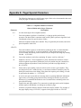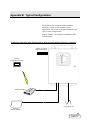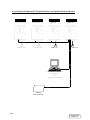
1
DISCONTINUED
PRODUCT
S I T E
M O N I T O R I N G
RCM8CE & RCM8DO
Remote Contact Module
INSTALLATION &
USER MANUAL
DISCONTINUED
PRODUCT
DISCONTINUED
PRODUCT
TABLE OF CONTENTS
NOTE..........................................................................................................................................5
Section 1: INTRODUCTION......................................................................................................1
Specifications................................................................................................................................................ 1
Display and Controls .................................................................................................................................... 2
Communications Ports .................................................................................................................................. 4
Common Alarm Relay Output ...................................................................................................................... 4
Alarm Relay Outputs (RCM8DO only)........................................................................................................ 4
Section 2: Installation..............................................................................................................5
Unpacking and Inspection............................................................................................................................. 5
Mounting Instructions................................................................................................................................... 5
Physical Connections.................................................................................................................................... 5
Settings and Connections.............................................................................................................................. 7
Modem Settings .......................................................................................................................................... 12
Terminal Parameters ................................................................................................................................... 12
Section 3: RCM8 Menus ........................................................................................................15
Accessing the Setup Menus ........................................................................................................................ 15
Configuration..................................................................................................................................... 17
Setup Input Options Menu................................................................................................................. 18
Alarms Review .................................................................................................................................. 20
Alarms Clear...................................................................................................................................... 21
Set Clock............................................................................................................................................ 21
Set Modem Options ........................................................................................................................... 22
Set Terminal Options......................................................................................................................... 25
Set 485 Options ................................................................................................................................. 26
Display SS Alarm Block.................................................................................................................... 27
Set New Password ............................................................................................................................. 27
Exit..................................................................................................................................................... 27
Section 4: Operation..............................................................................................................29
Receive Alarms........................................................................................................................................... 29
Silence Alarms............................................................................................................................................ 29
View Input Status........................................................................................................................................ 29
Review Alarms............................................................................................................................................ 30
Pager Operation .......................................................................................................................................... 30
Section 5: RCM8 Equipment Maintenance...........................................................................31
Safety Instructions ...................................................................................................................................... 31
Battery......................................................................................................................................................... 31
Fuse............................................................................................................................................................. 31
Appendix A: Pager Special Characters .............................................................................. A-1
Appendix B: Typical Configurations................................................................................... B-1
DISCONTINUED
PRODUCT
NOTE
This equipment has been tested and found to
comply with the limits for a Class A digital device,
pursuant to part 15 of the FCC rules. These limits
are designed to provide reasonable protection
against harmful interference when the equipment is
operated in a commercial environment.
This
equipment generates, uses, and can radiate radio
frequency energy and, if not installed and used in
accordance with the instruction manual, may cause
harmful interference to radio communications.
Operation of this equipment in a residential area is
likely to cause harmful interference in which case
the user will be required to correct the interference
at his own expense.
DISCONTINUED
PRODUCT
DISCONTINUED
PRODUCT
Section 1: INTRODUCTION
Contact Liebert Environmental
Service & Support at
800-543-2778 regarding
installation, operation, or
warranty issues.
The Liebert RCM8CE and RCM8DO Remote Contact Monitors
annunciate alarms by monitoring eight contact-closure points,
each point wired directly to the RCM8.
When the RCM8 receives an alarm signal, a piezoelectric siren
sounds and the LED illuminates for the corresponding contact
point (1 through 8). A text interface to a video terminal or PC
emulating a terminal session is used to configure the operating
parameters, and can remain connected to receive userprogrammed alarms messages.
In addition to monitoring alarm signals from locally-connected
equipment, the RCM8 can also dial out via modem to: remote
computer; another RCM8 acting as a repeater; numeric pager; or
alphanumeric pager. The RCM8DO features 8 additional
contact-closure outputs that mimic the state of the alarm LEDs.
Up to four RCM8 units can be connected in a local, multi-point
monitoring configuration. This gives added flexibility to monitor
up to 32 contact points. The RCM8 also communicates with the
Liebert SiteScan centralized monitoring system.
Specifications
Electrical Specifications:
Installation Category (Overvoltage Category): II
Transient Overvoltage: 2500 Volts Maximum
Voltage: 120 VAC/240 VAC, +/-10% of nominal
Current: 0.07/0.04 Amperes
Power: 8.5 VA
Phase: 1
Frequency: 50/60 Hz
Battery Backup: 1-hour nominal
Communications:
2 standard 25-pin, EIA-232 modem and terminal
Proprietary EIA-422 protocol to Liebert SiteScan system
Proprietary EIA-485 protocol to multiple RCM8 units
Common alarm output, Form-C dry-contacts
Piezo-electric alarm: 100 dB at 30 cm, 2900 +/-500 Hz
Liebert RCM8 • 1
DISCONTINUED
PRODUCT
Environmental Conditions:
Operating Temp: 5°C to 40°C
Operating Relative Humidity: 0%-95% (non-condensing)
Operating Altitude: up to 2,000 meters
Pollution Degree: 2
Enclosure Type: NEMA 1 (for indoor use only)
Enclosure Protection: IP30 (protection against solid foreign
objects 2.5mm or greater, no protection from water)
Display and Controls
Alarm LEDs (Red)
For all unit configurations except Master Repeater units, each
alarm LED corresponds to an input and illuminates on alarm
(after the programmable alarm delay expires). For Master
Repeaters, its LEDs illuminate with the corresponding alarm
point from the unit in alarm: ie, Master Repeater alarm 1 will
illuminate when any of points 1, 9, 17 or 25 is in alarm. When a
connected unit goes off-line from the EIA-485 bus, all eight
LEDs flash, indicating a problem.
Normal LED (Green)
When input power is OK, the Normal LED illuminates (solid). If
the RCM8 is running on the NiCad backup battery, the Normal
LED blinks.
Audible Alarm
You can disable the audible
beeper by removing the P1
connector on the RCM8
circuit board. See Figure 3
in Chapter 2.
When any alarm is active, an audible alarm sounds. If alarms are
non-latching (not requiring acknowledgment to reset), the beeper
stops when the alarm situation no longer exists. If the alarm is
latching, the beeper continues to sound until an operator
acknowledges the alarm condition and resets the beeper.
2 • User Manual (7/99)
DISCONTINUED
PRODUCT
Section 1: INTRODUCTION
Silence/Reset Switch
The Silence/Reset switch turns OFF the audible alarm. If DIP
Switch SW1-8 is ON, the common alarm relay output will reset
with the Silence/Reset switch.
ON/OFF Switch
The RCM8 has a power ON/OFF switch located inside the
enclosure. Refer to Figure 1 below. When wiring the dry contact
connections, this switch should be in the OFF position. For
normal operation, the switch should be in the ON position.
Figure 1. Component Arrangement
Liebert RCM8 • 3
DISCONTINUED
PRODUCT
Communications Ports
The RCM8 has five physical connection ports:
Refer to Chapter 2 of this
manual and the section
immediately following for
information on installation and
configuration using these
communications ports.
•
EIA-232 (PC/Terminal) Port (DCE)—Accommodates a
personal computer or VDT for setup and message display
•
EIA-232 Modem Port (DTE)—Accommodates a modem
for alarm reception and remote message transmission
•
EIA-485 Port—Allows multiple RCM8 units to be "daisychained" together using twisted-pair wires
•
EIA-422 SiteScan Port—Accommodates a Liebert
SiteScan connection
•
Common Alarm Relay Output—Accommodates a
secondary warning device
Refer to Figure 1 Component Arrangement, and Figure 3
Physical Connections and DIP Switches.
Common Alarm Relay
Output
Alarm Relay Outputs
(RCM8DO only)
The common alarm relay output is used to connect to a
secondary warning device -- such as a horn or light, up to 3
Ampere @ 24 Volts DC -- that activates on alarm. When an
alarm is present, the contacts close and the external warning
device is activated. The common alarm relay may be reset using
the Silence/Reset switch.
On RCM8DO models, one relay output corresponding to each
alarm channel is provided. There is no additional programming
logic or setup involved: each Form-A Normally Open (N.O.)
relay will energize when the corresponding channel goes into
alarm and the front panel LED is illuminated. The relays are
rated for up to 1 Ampere @ 24Volts DC.
4 • User Manual (7/99)
DISCONTINUED
PRODUCT
Section 2: Installation
This section describes the installation procedure for monitoring
systems using the RCM8. Installation includes:
Unpacking and
Inspection
Mounting Instructions
•
Unpacking and Inspection
•
Mounting the RCM8 at the designated site
•
Making RCM8 physical connections based on application
needs
•
Configuring the modem
Inspect the package when delivered by the freight carrier. If the
shipping container is damaged, check for internal damage and
file a claim with the carrier if necessary. If the container is
undamaged, unpack the RCM8 and inspect it for obvious
damage. If it is necessary to ship the RCM8, use the original
shipping container if possible to ensure safe transportation.
After the DIP switches and jumpers are set correctly (as
described in the section entitled Settings and Connections),
mount the RCM8 on a wall at the selected location. THIS
DEVICE IS FOR INDOOR USE ONLY!
Mounting Requirements:
Enclosure Type: NEMA 1
Hole Pattern: 15.44" x 7.00" (392.23mm x 177.80mm)
Fasteners: Use four 1/4" (6mm) bolts
Weight: 15 lbs. 8 ozs. (7.2kg)
Figure 2 describes the physical dimensions of the RCM8.
Physical Connections
The RCM8 can be installed and configured at the hardware level
to your specific application according to several configurations:
•
A single RCM8 (with or without a PC or video display
terminal connected)
•
Multiple RCM8 units (Master, Slaves, and Repeaters) in a
local configuration
•
RCM8 with SiteScan central monitoring system
Liebert RCM8 • 5
DISCONTINUED
PRODUCT
•
RCM8 with local, short-haul modems
•
RCM8 with dial-up modems to remote locations and pagers
•
RCM8 monitoring multiple remote locations from a central
location
Diagrams in Appendix B at the end of this manual describe
possible RCM8 configurations.
Dwg No. 154559, Sheet 1 of 3
8/21/97
Figure 2. Exterior and Mounting Dimensions
6 • User Manual (7/99)
DISCONTINUED
PRODUCT
Section 2: Installation
Settings and
Connections
To connect the RCM8:
1. Set the SW1 DIP Switches as described in the tables below:
Refer to Figure 3 when
making physical connections
to the RCM8. Refer also to
Appendix B to define the
application you wish to install.
EIA-485
Master/Slave
3
OFF
ON
M
S
EIA-485
Baud
4
OFF
ON
9600
1200
Switch
RCM8 (Input #)
1 (1-8)
2 (9-16)
3 (17-24)
4 (25-32)
Latching
Alarms
5
OFF
ON
OFF
ON
SW1 Switches 1 and 2—Address
1
2
OFF
ON
OFF
ON
X
X
X
X
X
X
X
X
Repeater
6
OFF
ON
OFF
ON
Terminal
Baud Rate
7
OFF
ON
1200
2400
Alarm Relay
(Silence/Reset)
8
OFF
ON
OFF
ON
DIP Switch SW1 Descriptions
•
Address (1 and 2)—Addressing allows up to four RCM8
units to be linked together. Overlapped addresses are
allowed only for dial-up operation without SiteScan.
•
EIA-485 Master or Slave (3)—If ON, the Master unit polls
the EIA-485 Slaves and has dial-out capability for the
connected units. For Slave units at the ends of each EIA-485
string, set P4 jumper to IN. For all other units, set the P4
jumper to OUT. Modems do not directly attach to slave
units.
•
EIA-485 Baud (4)—9600 baud works for most multipleunit applications. If communications are not working: check
cable distance; check for a noisy communications
environment; or try using 1200 baud.
•
Latching Alarms (5)—When ON, alarms will not clear
until the Silence/Reset switch is pressed and held for two
seconds.
•
Repeater (6)—A repeater RCM8 unit is connected at a
different location to echo alarms received by the primary
unit(s). When ON, the eight inputs of the repeater unit are
disabled and the display echoes incoming alarms. Master
repeaters display all alarms. Slave repeaters display alarms
only from RCM8 with a matching address.
Liebert RCM8 • 7
DISCONTINUED
PRODUCT
Figure 3a. Physical Connections and DIP Switches (RCM8CE)
8 • User Manual (7/99)
DISCONTINUED
PRODUCT
Section 2: Installation
Figure 3b. Physical Connections and DIP Switches (RCM8DO)
Liebert RCM8 • 9
DISCONTINUED
PRODUCT
•
Terminal Baud Rate (7)—1200 or 2400 baud selectable.
7 data bits, even parity, 1 stop bit are fixed.
•
Common Alarm Relay (Silence/Reset) (8)—The common
alarm relay energizes with any input alarm or received
alarm. If Silence Reset is ON, the relay de-energizes when
the audible alarm is silenced. If OFF, the common alarm
relay remains energized until the input alarm is cleared.
2. Make the following physical connections as applicable.
Refer to Figures 1 and 3.
Power
The RCM8 is shipped with the
backup battery disconnected.
To connect the battery during
installation: plug the 2-wire
connector to P5; then set the
P10 jumper to IN.
Refer to Figure 3.
Connect power to a 120 VAC or 240 VAC source, 50 or
60 Hz. Select the proper input voltage using the voltage
switch located next to the ON/OFF switch.
Be sure to provide proper earth grounding for the unit by
connecting the clearly marked earth grounding conductor to
earth ground on the input power source. Caution: failure
to connect earth grounding conductor may result in
operator injury.
This monitoring device requires an equipment switch or
circuit breaker employed in the building installation as a
circuit-disconnecting device. The disconnecting device shall
be located in close proximity to the monitoring device and
within easy reach of the operator. The disconnecting device
shall be marked as the disconnecting device for the monitor
panel.
Alarm Input Connections
Liebert recommends a
maximum cable length of 300
feet with 22 AWG wiring.
Use 18-22 AWG stranded pair cable for each input channel.
The cable is terminated at the appropriate terminal block
number (1-8). Make connections to the common alarm relay
output if necessary.
Computer or Terminal
Liebert recommends a
maximum cable length of 50
feet or use of a short-haul
modem for any device
connected to the PC EIA-232
port.
The PC or terminal port is a standard EIA-232 (DCE 25-pin
female, 1200 or 2400 baud) connection for a personal
computer, video display terminal connection, short-haul
modems or other device utilizing a serial port.
A PC must be connected to an RCM8 to configure it. You
do not need the PC after the initial configuration unless you
want to change the setup or view alarms on-screen as they
occur. A serial printer can be connected to this port if you
wish to print and retain a hard-copy of alarms.
10 • User Manual (7/99)
DISCONTINUED
PRODUCT
Section 2: Installation
Proprietary EIA-485
Liebert recommends a
maximum cable length of 3280
feet. Use a twisted-pair wire
and maintain polarity (+/−). The
slave unit at the end of the
string (the last RCM8) must
have the P4 jumper set to IN.
The P4 jumper on all other
units must be set to OUT.
The EIA-485 port is a proprietary connection that allows
you to network multiple RCM8 units in a "daisy-chain"
configuration. Multiple unit configurations must include a
"master" unit to which three or four "slave" units can be
connected; repeaters may also be daisy-chained.
Use 18-22 AWG stranded, twisted-pair wires. Run the EIA485 cable from the EIA-485 terminal block to other EIA-485
terminal blocks in the same string. Set the P4 jumper on the
last slave unit IN: set the P4 jumper on all other units OUT.
Maintain +/− polarity.
Proprietary EIA-422
The EIA-422 is a proprietary connection to a Liebert
SiteScan system. The SiteScan system data file must include
the RCM8 as a contact closure module. Alarm text for
RCM8 units connected to SiteScan is entered through the
RCM8 using a PC or terminal. In multiple RCM8
configurations, each slave unit transmits only its own
alarms; the master unit transmits all alarms.
Liebert recommends a
maximum cable length of 3280
feet. Maintain polarity (+/−).
Run the EIA-422 cable from the EIA-422 terminal block on
the master unit to the appropriate terminal block number of
the SiteScan system.
3. Apply power to the system and configure the unit
parameters as described in Section 3 of this manual.
Modem
Liebert recommends a
maximum cable length of 50
feet for any device connected
to the modem EIA-232 port.
The modem port is a standard EIA-232 (DTE 25-pin male,
1200 or 2400 baud) connection for a dial-up modem, null
modem cable, short haul modem, or leased line. Alarms that
are configured to transmit use this port.
First, connect the modem, power, and phone cables as
directed in the documentation that came with your modem.
Next, using a standard 25-conductor EIA-232 cable, connect
one end to the 25-pin Modem port on the RCM8. Connect
the other end to the 25-pin EIA-232 port on the modem. Be
sure all connections are secure to ensure proper operation.
Communications parameters for this port are fixed 7 data
bits, even parity, and 1 stop bit. Refer to the dial-up
modem setup information later in this Section for other
settings related to the modem.
Liebert RCM8 • 11
DISCONTINUED
PRODUCT
Modem Settings
Data compression needs to be disabled on external modems used
with RCM8. On U.S. Robotics Sportster® modems, the modem
command to disable data compression is AT&K0.
Error correction may or may not need to be disabled, depending
on your application and premise equipment. The modem
command AT&M4 allows the modem to select the error
correction mode; AT&M0 will manually disable error
correction.
Modem commands can be directly issued via the Modem PassThru mode in the RCM8 Modem Configuration menu. Refer to
Section 3.
® Sportster is a registered trademark of 3Com Corporation
Terminal Parameters
A personal computer (PC) or video display terminal (VDT) is
necessary to configure the RCM8. On PC’s, a terminal
emulation package is typically included with the operating
system: on Windows 3.1, Terminal is located in the Accessories
program group; on Windows 95/98, the Hyperterminal
application is typically located in its own folder Accessories.
The steps below outline the typical configuration needed to
connect PC running Hyperterminal to RCM8, using a regular
serial cable direct connection.
Windows 95 / 98
1. Start HyperTerminal by clicking
Start/Programs/Accessories/HyperTerminal. Double click
the HyperTerminal icon.
2. Press ESC (escape key) to exit out of new connection dialog
box.
3. To establish a new session for communicating to RCM8, go
to File / Properties. Select Direct to Com* where Com* is
the appropriate Com port for your PC. Any information in
the Area Code and Phone Number fields will be greyed-out
and will not be used.
12 • User Manual (7/99)
DISCONTINUED
PRODUCT
Section 2: Installation
4. Click on the Configure button. Select the corresponding
baud rate as set on RCM8 DIP Switch 1-7; select 7 data bits;
Even parity; 1 stop bit; No flow control. Click on OK to
confirm entry and return to previous dialog box.
5. Click on the Settings tab, and the ASCII Setup button.
Ensure the Send line ends with line feeds check box is
selected, and that the Echo typed characters locally check
box is de-selected. Click on OK to confirm entries and exit
from dialog box.
6. IMPORTANT: Save the connection information at this
time by going to File / Save As.
7. Once the communication parameters are set and saved,
connect with the RCM8 by selecting Call / Connect, or click
on the telephone icon in the menu bar.
Liebert RCM8 • 13
DISCONTINUED
PRODUCT
DISCONTINUED
PRODUCT
Section 3: RCM8 Menus
The RCM8 Main Menu has 12 options that let you set
configuration parameters.
Accessing the Setup
Menus
After you have installed your RCM8 system you must set the
software parameters using the RCM8 Main Menu and Submenus. The diagram on the following page describes the RCM8
menu system.
You can access the Main Menu from a local computer connected
to the RCM8 or remotely via computer/modem.
To access the RCM8 Main Menu from a LOCAL
COMPUTER:
1. Turn on the computer and the RCM8.
2. Press Space Bar to begin the login process.
3. Type the RCM8 password, then press ENTER to access the
Main Menu. The factory-set password is “RCM8”.
4. At any time during the configuration, press Esc to back up
through the menus to return to the Main Menu:
LOG ON:****
RCM8 TERMINAL MENU
1. Configuration
2. Setup Input Options Menu
3. Alarms Review
4. Alarms Clear
5. Set Clock
6. Set Modem Options
7. Set Terminal Options
8. Set 485 Options
A. Display SS Alarm Block
B. PCMCIA Menu
P. Set New Password
X. Exit
Liebert RCM8 • 15
DISCONTINUED
PRODUCT
Figure 4. Menu Structure
16 • User Manual (7/99)
DISCONTINUED
PRODUCT
Chapter 3: Main Menu and SubMenus
To access the RCM8 Main Menu VIA MODEM:
1. Make sure RCM8 and attached modem are turned on and
properly configured.
2. On the remote PC, set up terminal emulation session for
dial-out access – Connect Using an attached modem, rather
than direct connect to a com port.
3. Once a connection has been established with the RCM8,
press Space Bar to initiate the log-in process.
4. Type the RCM8 password, then press Enter to gain access to
the RCM8. The factory-default password for modem access
is also “RCM8”.
5. From here, continue to Step 3 of the local login process.
Configuration
The Configuration option from the Main Menu lets you view the
current RCM8 settings.
1. Press 1 to display the Configuration menu:
RCM8 V4.0 CONFIGURATION - MON 07-05-99 18:03:20
SITE ID = WEST WING COMPUTER ROOM
PAGER ID - 5551149
IN DELAY NO DIAL ALT
DIAL
MESSAGE
MM:SS NC
A
CODE
B
------------------------------------------01 00:00 NO
1
0
0
WATER UNDER FLOOR
02 00:00 NO
1
0
0
HIGH TEMP
03 05:00 NC
2
&
1
DOOR HELD OPEN
04 00:00 NO
0
0
0
CLOGGED FILTER
05 00:00 NO
0
0
0
HIGH HUMIDITY
06 00:00 NO
0
0
0
CONTACT #6
07 00:00 NO
0
0
0
CONTACT #7
08 00:00 NO
0
0
0
CONTACT #8
RCM8 Phone Number =
Phone Number 1
= 9,5551212,,,,,911##
Phone Number 2
= A9,18007596366
Dial Prefix
= ATE1X4DT
Redial Tries
= 2
Redial Interval
= 30
Modem
= CONNECTED
Modem Baud Rate
= 1200
EIA-485 Online Units =
This is a view-only screen. Use the remaining Main Menu
options to make changes or reset the values shown in this
screen.
2. Press Esc to return to the Main Menu.
Liebert RCM8 • 17
DISCONTINUED
PRODUCT
Setup Input Options
Menu
The Setup Input Options item lets you configure RCM8
information governing alarm delays, contact status, dial codes,
alarm messages, site and pager IDs.
To configure input options:
1. From the Main Menu, press 2 to display the RCM8 Setup
menu:
RCM8 SETUP MENU
1. Set Delays
2. Set NO or NC or BAT
3. Set Dial Code A
4. Set Alternate Dial Option
5. Set Dial Code B
6. Set Alarm Messages
7. Set Site Id
8. Set Pager Id
<ESC> to Quit
2. Press the number corresponding to the parameter you wish
to configure, then enter the appropriate data as follows:
Set Delays (1)
Set the period of time that must expire before an alarm
condition will trigger the alarm.
Press 1 to access the input (dry contact point) delays setup
option, then enter the specific contact point (01 - 08) for
which you will set a delay. Next, enter the time delay in
minutes and seconds (00:00 to 99:59) for this contact point.
Press Enter to return to the Setup menu.
Set NO or NC or BAT (2)
Configure the contacts as Normally Open (NO), Normally
Closed (NC), or Battery (BT). Battery disables the contact
closure and monitors RCM8 battery operation. If the RCM8
loses AC power and reverts to battery, the alarm is turned
ON.
Press 2 to configure the contact status. Enter the specific
contact point to configure (01 - 08), then type NO, NC, or
BT. Press Enter to return to the Setup menu.
18 • User Manual (7/99)
DISCONTINUED
PRODUCT
Chapter 3: Main Menu and SubMenus
Set Dial Code A (3)
Select an alarm option for transmission through the modem
port.
•
0=Disabled, do not transmit via modem
•
R=Transmit alarm to another RCM8
•
1=Transmit alarm to remote device via PHONE
NUMBER 1
•
2=Transmit alarm to remote device via PHONE
NUMBER 2
Remote devices connected to Phone Numbers 1 and 2 can be
RCM8s, terminals, or (regular or numeric) pagers.
Press 3 to select a modem port transmission code. Enter the
specific contact point to configure (01 - 08), then type the
desired transmission option. Press Enter to return to the
Setup menu.
Set Alternate Dial Option (4)
Configure instructions for alarm transmission to a second
phone number.
•
0=Disabled, do not transmit to second phone number
•
&=Dial and transmit alarm to both dial codes A and B.
(See Set Dial Code B below)
•
#=Dial and transmit alarm to either dial code A or B
Press 4 to select an alternate dial option. Enter the specific
contact point to configure (01 - 08), then type the desired
transmission option. Press Enter to return to the Setup menu.
Set Dial Code B (5)
Select an option for alarm transmission to a secondary phone
number.
•
0=Disabled, do not transmit
•
R=Transmit alarm to another RCM8
•
1=Transmit alarm to another device via PHONE
NUMBER 1
•
2=Transmit alarm to another device via PHONE
NUMBER 2
Press 5 to the Dial Code B option. Enter the specific contact
point to configure (01 - 08), then type the desired
transmission option. Press Enter to return to the Setup menu.
Liebert RCM8 • 19
DISCONTINUED
PRODUCT
Set Alarm Messages (6)
Enter a custom alarm message to display each time its
associated input alarm is triggered. You can enter up to 25
characters.
For example, you might wish to
enter the alarm text for input 01
as "Call Maint. Jim at x9999".
Each time an alarm occurs on
contact point 01, the RCM8
displays the message to call
Jim.
Press 6, then enter the specific contact point to configure
(01 - 08). The existing message is displayed with a prompt
to enter the new message. Type the desired alarm text, then
press Enter to return to the Setup menu.
Set Site ID (7)
Enter a descriptive header for all alarms transmitted through
this RCM8 unit. This message is not unique to a contact
point. The Site ID is a convenient way to identify the source
of the alarm. Site ID can be a maximum of 30 characters.
Press 7 to access the Site ID configuration parameter. The
existing Site ID is displayed with a prompt to enter a new
ID. Type the desired text, then press Enter to return to the
Setup menu.
A reference of special
characters commonly used
when inputting a pager key
sequence is included in
Appendix A at the end of this
manual.
Set Pager ID (8)
The RCM8 is designed to work with alpha-numeric pagers.
Enter the pager key sequence if the RCM8 is to
communicate alarm messages to an alpha-numeric pager. Be
sure to include any special characters such as commas when
entering the pager key sequence. The Set Pager ID field
specifies the actual pager phone number; it should not
include the access phone number for the alpha-numeric
paging company. Only one (1) alpha-numeric pager is
supported.
Press 8, then enter the pager key sequence. The existing
pager ID is displayed with a prompt to enter the new pager
key sequence. Type the desired number (including special
characters), then press Enter to return to the Setup menu.
Press Esc to exit the Setup menu and return to the Main
Menu. Changes made to this parameter are saved when you
press Esc.
Alarms Review
The Alarms Review option from the Main Menu displays recent
alarm history. The history stores up to
The Alarms Review option for
a master unit displays local
alarms only.
•
100 local alarms transmitted from non-repeater units
•
16 alarms transmitted from connected repeater units
20 • User Manual (7/99)
DISCONTINUED
PRODUCT
Chapter 3: Main Menu and SubMenus
To view the alarm history:
1. From the Main Menu, press 3 to display the alarm history.
Alarms Last Cleared at 08-15-97 13:41:37
07-05-99 13:05:21 WATER UNDER FLOOR
07-04-99 05:45:32 HIGH HUMIDITY
07-03-99 23:57:16 HIGH HUMIDITY
End - Press Space Bar for Menu
This is a view-only screen indicating when the alarms were
last cleared and listing the first 20 recorded alarms (by input
contact number).
2. If the history contains more than 20 alarms, press the
spacebar to view the next screen of 20 alarms.
3. When you are finished viewing the alarms, press Space Bar
or Esc to return to the Main Menu.
Alarms Clear
The Alarms Clear option from the Main Menu lets you clear the
alarm history log and reset each alarm input. If the RCM8 is a
master unit, this option clears the alarm history logs for each
connected slave unit.
From the Main Menu, press 4 to clear the alarm history log.
When the log is clear, the RCM8 returns to the Main Menu and
does not display any indication that the alarm history is cleared.
You can verify that the alarm history is cleared by pressing 3.
Alarms History from the Main Menu.
Set Clock
The Set Clock option from the Main Menu lets you reset the
internal date and time clock of the RCM8.
To set the clock:
If the RCM8 is a master unit, it
transmits its current date and
time to each connected slave
unit at the beginning of each
hour.
1. From the Main Menu, press 5. The RCM8 displays the date
and time as it is currently set in the unit and prompts you to
enter the new date and time.
Current Date/Time is MON 07-05-99 18:03:20
Enter New Date/Time (MM-DD-YY HH:MM)
2. Type the correct date and time (in a single string). The
format is MM-DD-YY HH:MM. The RCM8 automatically
sets the seconds count to 00.
3. Press Enter to change the date and time and return to the
Main Menu.
Liebert RCM8 • 21
DISCONTINUED
PRODUCT
Set Modem Options
Modem options are not
available for slave or repeater
units. The Master unit is
responsible for dial-out
operations for all slaves
connected on the EIA-485
network.
The Set Modem Options item from the Main Menu lets you
configure the telephone numbers and dialing parameters for
modem connected to the unit. You can also perform a test on the
communications port where the modem and phone are connected
to verify proper operation.
To set modem options:
1. From the Main Menu, press 6 to display RCM8 Modem
Setup Sub-menu:
RCM8 MODEM SETUP MENU
1. Set RCM8 Phone Number =
2. Set Phone Number 1
= 9,5551212,,,,,911##
3. Set Phone Number 2
= A9,18007596366
4. Set Modem Baud Rate
= 1200
5. Set Dial Prefix
= ATE1X4DT
6. Set Redial Tries
= 2
7. Set Redial Interval
= 30
8. Set Modem Messages
= Y
9. Set RCM8 Comm Check
= OFF
A. Set PH1 Comm Check
= OFF
B. Set PH2 Comm Check
= OFF
C. Set Modem Init String = AT&C1&D3S0=1&W0
I. Send Modem Init String
M. Enable Modem Pass-Thru Mode
<ESC> to Quit
This menu also shows the current configuration.
2. Press the number or letter corresponding to the parameter
you wish to configure, then enter the appropriate data as
follows:
If you are using a leased line
(or short-haul modem) for
alarm communication, enter
LEASED as RCM8 Phone
Number.
Set RCM8 Phone Number (1)
Enter the phone number of another RCM8 that will be
notified when an alarm occurs. You can use up to 40
characters in a phone number. Press Enter to return to the
Modem Setup menu.
Set Modem Phone Number 1 (2)
If two RCM8 units are
connected to a generic EIA232 device, enter LEASED as
Modem Phone Number 1.
Enter the telephone number (including any required special
characters) for the modem that will receive the alarm
indication. This modem can be in another RCM8 or in a
personal computer. You can use up to 40 characters in a
phone number. Press Enter to return to the Modem Setup
menu.
22 • User Manual (7/99)
DISCONTINUED
PRODUCT
Chapter 3: Main Menu and SubMenus
Set Modem Phone Number 2 (3)
Modem Phone Number 2 is not
a leased-line option.
Enter a phone number for another receiving modem (if
applicable). Press Enter to return to the Modem Setup menu.
Using an Alpha-Numeric Pager
When using an alpha-numeric pager, you must enter the
letter "A" before the pager access code phone number.
Refer to the sample screen on page 17 of this manual.
Note: most alpha-numeric paging services do not yet
support 2400 baud modem connections: use 1200 baud.
Using a Numeric Pager
When using a numeric page, an example of the pager
number that you enter is:
Phone Number 1 = 9,5551212,,,,,911##
Each comma forces the mode to pause for two seconds.
The 911 is the user-arranged “code” that identifies the
page as being from the RCM8. The ## signify the end of
the pager number and alarm code.
(See Appendix A on Page A-1 for additional
modem/pager characters.)
When using numeric pagers, you will have to experiment
with the number of commas that you need to enter in
order to get the correct delay before the message is sent.
The Set Pager ID field is left blank when using numeric
pagers.
Set Modem Baud Rate (4)
Enter 1 for 1200 or 2 for 2400. Press Enter to return to the
Modem Setup menu.
Set Dial Prefix (5)
Press 5 if you need to change the dial prefix. From the
factory, the Dial Prefix is entered as ATE1X4DT. Do not
change this dial prefix unless you are thoroughly familiar
with the Hayes command set. Press Esc to return to the
Modem Setup menu.
Set Redial Tries (6)
Enter a number (0-99) representing the number of times the
RCM8 will attempt to redial a phone number should the first
attempt fail. Press Enter to return to the Modem Setup
menu.
Liebert RCM8 • 23
DISCONTINUED
PRODUCT
Set Redial Interval (7)
Enter a number (0-99) representing the number of minutes
between redial attempts. Press Enter to return to the Modem
Setup menu.
Set Modem Messages (8)
Type Y(es) to enable, or N(o) to disable modem messages. If
enabled, all communications to the RCM8 are echoed to the
computer monitor, printer, or terminal connected to the EIA232 terminal port. This feature is useful to verify proper
modem operation. Press Enter to return to the Modem Setup
menu.
Set RCM8 Comm Check (9)
Enter the time (HH:MM) at which the RCM8 will send a
communications port check message. Type OFF to disable
this feature. If enabled, at the designated time, the RCM8
dials the RCM8 phone number (defined under Modem
Option 1) and transmits the date/time, Site ID, and the words
"COMM CHECK". Press Enter to return to the Modem
Setup menu.
Set PH 1 Comm Check (A)
Enable or disable the Phone Number 1 Comm check option
as described above. Press Enter to return to the Modem
Setup menu.
Set PH 2 Comm Check (B)
Enable or disable the Phone Number 2 Comm check option
as described above. Press Enter to return to the Modem
Setup menu.
Set Modem Init String (C)
This modem string is set correctly at the factory. Do not
change the Set Modem Init String.
Enable Modem Pass-Thru Mode (M)
This parameter lets you configure the modem through the
PC (if necessary). All of the modem commands are passed
through or displayed on the PC monitor.
3. When you are finished setting modem options, press Esc to
exit the Modem Setup menu and return to the Main Menu.
Changes made to this parameter are saved when you press
Esc.
24 • User Manual (7/99)
DISCONTINUED
PRODUCT
Chapter 3: Main Menu and SubMenus
Set Terminal Options
The Set Terminal Options Main Menu item lets you configure
the audible beep characteristics that are annunciated when an
alarm occurs and terminal/modem parity. This option also lets
you enable a communications check that sends a date and time
message at a specified hour each day.
To set terminal options:
1. From the Main Menu, press 7 to display the terminal options
Sub-menu:
RCM8 TERMINAL OPTIONS MENU
1. Set Number of Beeps = 5
2. Set Beeper Interval = 0
3. Set Terminal Comm Check = OFF
4. Set Term/Modem Parity = 7E
<ESC> to Quit
This menu also shows the current configuration for each
item.
2. Press the number corresponding to the parameter you wish
to configure, then enter the appropriate data as follows:
Set Number of Beeps (1)
Enter the number of times the RCM8 will beep per second
(0 to 5) on receipt of an alarm. Press Enter to return to the
Terminal Options menu.
Set Beeper Interval (2)
Enter the number of seconds (0 to 5) to elapse between
alarm beeps. (0=disabled). Press Enter to return to the
Terminal Options menu.
Set Terminal Comm Check (3)
Enter the time (HH:MM) at which the RCM8 will send a
communications check message to the monitor, printer, or
terminal connected to the EIA-232 Terminal port. Type OFF
to disable this feature. If enabled, at the designated time, the
RCM8 transmits the date/time, Site ID, and the words
"COMM CHECK". Press Enter to return to the Terminal
Options menu.
Set Term/Modem Parity (4)
Type 7E for seven data bits/even parity or 8N for eight data
bits/no parity. Seven data bits/even parity is the proper
setting for most applications.
3. When you are finished, press Esc to exit the Terminal
Options menu and return to the Main Menu. Changes made
to this parameter are saved when you press Esc.
Liebert RCM8 • 25
DISCONTINUED
PRODUCT
Set 485 Options
The Set 485 Options item from the Main Menu lets you address
slave units connected to a master through the EIA-485 port. If a
connected slave unit loses communication, the master RCM8
dials out to report the communication loss.
To set EIA-485 port parameters:
1. From the Main Menu, press 8 to display the Terminal
Options Sub-menu:
RCM8 EIA-485 OPTIONS MENU
* Master Unit Address = 1
1. Set Online Units =
2. Set Offline Units = 2 3 4
<ESC> to Quit
This menu also shows the current configuration for each
item.
2. Press the number corresponding to the parameter you wish
to configure, then enter the appropriate data as follows:
Master Unit Address
This address must always be 1 when master and slave units
are connected.
Set Online Units (1)
Add an address for a new active slave unit.
Set Offline Units (2)
Do not add an address for an offline unit.
3. When you are finished, press Esc to exit the EIA-485
Options menu and return to the Main Menu. Changes made
to this parameter are saved when you press Esc.
26 • User Manual (7/99)
DISCONTINUED
PRODUCT
Chapter 3: Main Menu and SubMenus
Display SS Alarm
Block
The Display SS Alarm Block option from the Main Menu sends
RCM8 information to a SiteScan alarm block. Alarm
information on up to 4 RCM8 units can be displayed by the
SiteScan.
To display the SiteScan alarm block:
1. From the Main Menu, press A to display the SiteScan alarm
block:
00 00 00 00 00 00 00 01
00 01 00 00 00 00 00 00
00 00 00 00 00 00 00 00
00 00 00 00 00 00 00 00
This is a view-only screen. The first eight sets of 00 in the
top row indicate the eight alarm points of RCM8 unit 1, and
so forth for 32 alarm points on four RCM8 units. The
example above shows an alarm on contact point number 8
on the first RCM8 unit and contact point number 2 on the
third RCM8 unit.
2. When you are finished viewing the information, press Esc to
return to the Main Menu.
Set New Password
The Set New Password option lets you assign a security
password protecting the RCM8 setup menu from unauthorized
changes.
To set a new password:
1. From the Main Menu, press P to access the new password
setup screen.
The factory-set password is
“RCM8.”
2. Type the desired new password then press Enter.
3. At the next prompt, retype the password exactly as you
entered it in step 2, then press Enter to confirm the
password. The new password is saved automatically.
4. Press Esc to exit the password setup screen and return to the
Main Menu.
Exit
The Exit option returns the system to the initial prompts for
Main Menu, Status, or Alarms.
Liebert RCM8 • 27
DISCONTINUED
PRODUCT
DISCONTINUED
PRODUCT
Section 4: Operation
When the RCM8 is installed and configured correctly, the unit
basically operates on its own receiving and responding to
incoming alarms. While the RCM8 is fully functional on its
own, it is more convenient to connect a computer or monitor to
facilitate operator interaction. This section describes the RCM8
operator functions.
Receive Alarms
The green and red LED lights on the RCM8 front panel indicate
normal operation and receipt of alarms. A computer, video
monitor, or printer also indicates incoming alarms by displaying
the alarm text configured in Setup.
Audible indication of alarms is given by a series of beeps
(configured in Setup) through the RCM8 or computer speaker.
Beeping continues until the alarm is silenced.
Silence Alarms
Alarms can be silenced and reset using the RCM8 front panel or
the computer keyboard.
To silence alarms from the RCM8, press the Silence/Reset
button on the front panel. This procedure also resets the input
contact that was involved with the alarm.
To silence the alarm at the PC and at the RCM8 from the
computer keyboard, press any key. This procedure does not reset
the input contact if it is latching.
View Input Status
You can view input status only if a computer or monitor is
connected.
To view input status:
1. Access the RCM8 logon screen by turning the RCM8 and
monitor ON or by dialing to the RCM8 via modem.
2. Type Space Bar to begin the login process.
The factory-set password is
“RCM8.”
3. Type the RCM8 password, then press Enter.
4. Press S to display the current input status (ON/OFF). If the
RCM8 unit you are polling is a master unit with slave units
connected, all inputs (including slave inputs) are displayed.
5. Press Esc to return to the log on screen.
Liebert RCM8 • 29
DISCONTINUED
PRODUCT
Review Alarms
The Alarms Review option for
a master unit displays local
alarms only.
The RCM8 maintains a history of alarms that have been received
by the unit. This alarm history can be accessed through the
RCM8 Terminal menu, or by accessing the RCM8 logon screen
and pressing A.
The alarm history log stores up to 100 local alarms transmitted
from non-repeater units or 16 alarms transmitted from connected
repeater units.
The RCM8 can display up to 20 alarms on a screen at a time. If
more than 20 alarms are logged, press the spacebar to view the
next screen.
Press Esc to return to the logon screen.
You can also view the alarm history log using the RCM8
Terminal menu as described previously in this manual.
Pager Operation
An integral feature of the RCM8 is its capability to
communicate alarm occurrence and alarm text to a pager.
The pager telephone number is entered in setup using the RCM8
Setup menu (accessed from the Terminal menu).
If the RCM8 is configured to dial a pager on alarm, the unit dials
the number entered in setup. Depending on your pager
capabilities, you may receive a beep and a phone number to call
or you may receive the alarm text transmitted from the RCM8.
Refer to your pager manual for its capabilities, configuration,
and operating instructions.
30 • User Manual (7/99)
DISCONTINUED
PRODUCT
Section 5: RCM8 Equipment Maintenance
Safety Instructions
CAUTION: DEVICE MUST BE ISOLATED OR DISCONNECTED
FROM THE HAZARDOUS LIVE VOLTAGE
BEFORE ACCESS.
NOTE:
CIRCUIT BREAKER/SWITCH DOES NOT OPEN
BATTERY CIRCUIT. OPEN CIRCUIT
BREAKER/SWITCH AND DISCONNECT BATTERY
PACK BEFORE SERVICING DEVICE.
NOTE:
WHEN THE FOLLOWING SYMBOLS ARE
DISPLAYED, THEY INDICATE:
CAUTION:
a.
Earth grounding conductor
b. .
Alternating Current
FAILURE TO CONNECT EARTH GROUNDING
CONDUCTOR MAY RESULT IN OPERATOR
INJURY.
CAUTION:
FAILURE TO ISOLATE OR DISCONNECT DEVICE
FROM THE HAZARDOUS LIVE VOLTAGE
BEFORE ACCESS MAY RESULT IN OPERATOR
INJURY SERVICING DEVICE.
Battery
Type:
Replacement:
Rechargeable Ni-Cad battery pack
Liebert P/N 133455P1
Disposal: CAUTION. DO NOT incinerate, short circuit,
or mutilate. May burst and
cause burns or release toxic
materials. Must be disposed of
in an EPA approved manner.
Fuse
Replacement:
Replace "F1" fuse with 1A, 250V F-M-T
(AGC-1 or ABC-1)
Liebert P/N G12-4000
Liebert RCM8 • 31
DISCONTINUED
PRODUCT
DISCONTINUED
PRODUCT
Appendix A: Pager Special Characters
The following characters are valid for most pagers. Refer to the documentation that came
with your pager for additional information.
Table A–1 Telephone Number Characters
Remote Modem and/or Pager Characters
Character
0–9
Description
Are the actual digits of the telephone number.
!
Forces the modem to perform a “hook flash” (i.e. hang up quickly and release)
operation. The hook-flash is sometimes used in office phone systems to signal the local
switchboard to listen for special codes to follow.
-
Make the telephone number more readable. They are ignored by the modem, and can be
placed anywhere in the field.
()
<SPACE>
,
Forces the modem to pause 2 seconds before continuing to dial. A comma should be
used when you must dial “9” to get an outside line. If the modem must pause for
several seconds after dialing 9 for an outside line, the complete dial string may looking
like this: 9,,555-8243.
W
Causes the modem to wait before continuing. W means “wait for a dial tone.”
R
Stands for “Reverse.” The R command is a prefix which tells the modem to connect
with an originate-only modem. Without the prefix, the modem may not communicate
with an originate-only modem. If used, R must be prefixed to any digits dialed, i.e.
R 9, 555-8325.
T, P
Selects tone or pulse dialing. Only one of these can be used in a given number. They
are both prefixes, the T stands for tone (i.e. touch tone) and the P stands for pulse. By
default, the modem uses tone dialing. If the phone line requires pulse dialing, a P must
be prefixed to the number, i.e. P 555-8325.
@
Is used to wait past a recorded voice message that is requesting additional information
input such as a recording giving instructions for entering an extension or password.
When used, @ commands the modem to wait 5 seconds before continuing to the next
part of the dial string.
#
Signifies the end of the number. Two consecutive pound signs at the end of telephone
number signify to RCM8 that it is dialing-out to numeric pager.
*
Generates a separator character between fields in the display window. For example, if
the pager display string is 555*8325, it appears in the pager window as 555-8325.
A-1
DISCONTINUED
PRODUCT
DISCONTINUED
PRODUCT
Appendix B: Typical Configurations
The RCM8 can be configured with tremendous
flexibility, in order to accommodate various
applications. The following diagrams illustrate some
typical system configurations.
Refer to Chapter 2 for complete explanation of DIP
Switch settings.
Standalone Operation with Optional Pager Dial-out and Optional SiteScan Connection
Master #1 Typical
DIP Switch Setting
Numeric
or Alphanumeric Pager
External Modem
SiteScan
SiteLink Module
Alarm Inputs 1-8
B-1
DISCONTINUED
PRODUCT
Local String with Optional PC/Terminal Interface and Optional SiteScan Interface
Optional Slave #4
Optional Slave #3
Inputs 25-32
Inputs 17-24
Slave #2
Inputs 9-16
Master #1
Inputs 1-8
PC with Terminal Emulation
Application
Or
Video Display Terminal
SiteScan
SiteLink Module
B-2
DISCONTINUED
PRODUCT
Local String with Master Repeater, and Optional Pager Dial-out
Optional Slave #4
Optional Slave #3
Inputs 25-32
Inputs 17-24
Slave #2
Inputs 9-16
Master #1
Inputs 1-8
“Main Computer Room”
Master Repeater
“24-Hour Attended
Security Station”
B-3
DISCONTINUED
PRODUCT
Liebert Global Services Remote Monitoring
Master #1
Optional
Additional
Slave Units
Liebert Global Services
24 x 7 x 365
Customer Response
Center
Inputs 1-8
SiteScan Remote Dial-Up Monitoring
Master #1
Optional
Additional
Slave Units
Master Repeater
Inputs 1-8
SiteScan
SiteLink Module
“Remote Facility”
“Central Monitoring Site”
B-4
DISCONTINUED
PRODUCT
Multiple Remote Sites Monitored from Central Location
Location #1
Master
Repeater
Location #2
Location #3
Location #4
SiteScan
SiteLink Module
B-5
DISCONTINUED
PRODUCT
RCM8CE & RCM8DO
Remote Contact Module
LIEBERT CORPORATION
With more than 500,000 installations around the globe, Liebert
is the world leader in computer protection systems. Since its
founding in 1965, Liebert has developed a complete range of
support and protection systems for sensitive electronics:
•
Environmental systems: precision air conditioning from
1.5 to 60 tons.
•
Power conditioning and UPS with power ranges from 250
VA to more than 1000 kVA.
•
Integrated systems that provide both environmental and
power protection in a single, flexible package.
•
Monitoring and control – on-site or remote – from systems
of any size or location.
•
Service and support, through more than 100 service
centers around the world, and a 24-hour Customer
Response Center.
LIEBERT EUROPE
LIEBERT ASIA
GLOBE PARK
1
MARLOW
BUCKINGHAMSHIRE SL7 1YG
UNITED KINGDOM
+44.1628.403200 PHONE
+44.1628.403203 FAX
19/F, CAUSEWAY BAY PLAZA
489 HENNESSY ROAD
CAUSEWAY BAY
HONG KONG
852.2.572.2201 PHONE
852.2.831.0114 FAX
LIEBERT W EB SITE
http://www.liebert.com
While every precaution has been taken to ensure accuracy and
completeness in this literature, Liebert Corporation assumes no
responsibility, and disclaims all liability for damages resulting from use of
this information or for any errors or omissions.
© 1999 Liebert Corporation. All rights reserved throughout the world.
Specifications subject to change without notice.
All names referred to are trademarks or registered trademarks of their
respective owners.
SL-31024 (12/99)
Printed in U.S.A.
DISCONTINUED
PRODUCT
THE COMPANY BEHIND
THE PRODUCTS
1050 DEARBORN DRIVE
P.O. BOX 29186
COLUMBUS, OHIO 43229
800.877.9222 PHONE
614.841.6022 FAX