1
Paulson-Cheek Mechanical
6145 Northbelt Parkway
Suite F
Norcross, GA 30071
770. 729. 0076
770. 729. 1076 Fax
Pinewood Atlanta – Phase 1A
Building 3
Fayetteville, GA
HVAC O&M Manuals
6/5/2014
General Contractor:
Group VI Construction, LLC.
Mechanical Engineer:
Paulson-Cheek Mechanical, Inc.
Mechanical Contractor:
Paulson-Cheek Mechanical, Inc.
Section 1
Rooftop Units
Section 2
Exhaust Fans
Section 3
Electric Heaters
Section 4
Variable Frequency Drives
Section 5
Starters
O&M COVER SHEET
SECTION: 1
PRODUCT: ROOFTOP UNITS
Paulson-Cheek Mechanical, Inc.
6145 Norhtbelt Parkway, Suite F
Norcross, GA 30071
PROJECT: Pinewood Atlanta - Building 3
PHONE: 770-729-0076
FAX:
770-729-1076
LOCATION: Fayetteville, GA
Paulson-Cheek Mechanical, Inc.
ARCHITECT'S/ENGINEER'S STAMP
Paulson-Cheek Mechanical, Inc.
DATE RECEIVED:
MANUFACTURER:
SUPPLIER:
SUBMITTED DATE:
X
06/05/14
JCI
JCI
06/05/14
NO ERRORS DETECTED
CORRECT EXCEPTIONS NOTED
THIS APPROVAL OF SHOP DRAWINGS DOES
NOT RELIEVE THE SUBCONTRACTOR OR VENDOR
FROM THE REQUIREMENTS OF THE CONTRACT
DOCUMENTS.
CHECKED BY:
DATE CHECKED:
O&M Section Sheets
WILLIAM HAGLER
06/05/14
6/5/2014
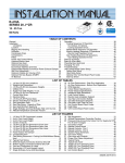
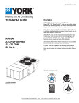
R-410A
SERIES 20 J**ZJ
15 - 25 Ton
60 Hertz
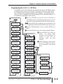
TABLE OF CONTENTS
General . . . . . . . . . . . . . . . . . . . . . . . . . . . . . . . . . . . . . . . . . . 2
Installation . . . . . . . . . . . . . . . . . . . . . . . . . . . . . . . . . . . . . . . . 5
Limitations . . . . . . . . . . . . . . . . . . . . . . . . . . . . . . . . . . . . 5
Location. . . . . . . . . . . . . . . . . . . . . . . . . . . . . . . . . . . . . . . . 7
Rigging And Handling . . . . . . . . . . . . . . . . . . . . . . . . . . . . . 7
Ductwork . . . . . . . . . . . . . . . . . . . . . . . . . . . . . . . . . . . . . . 12
Condensate Drain . . . . . . . . . . . . . . . . . . . . . . . . . . . . . . . 13
Compressors. . . . . . . . . . . . . . . . . . . . . . . . . . . . . . . . . . . 13
Filters . . . . . . . . . . . . . . . . . . . . . . . . . . . . . . . . . . . . . . . . 13
Power And Control Wiring. . . . . . . . . . . . . . . . . . . . . . . . . 14
Optional Electric Heat . . . . . . . . . . . . . . . . . . . . . . . . . . . . 26
Optional Gas Heat. . . . . . . . . . . . . . . . . . . . . . . . . . . . . . . 27
Options/Accessories . . . . . . . . . . . . . . . . . . . . . . . . . . . . . 29
Economizer And Power Exhaust Set Point Adjustments . 29
Optional BAS-Ready Economizer Power Exhaust
Damper Set Point Adjustment. . . . . . . . . . . . . . . . . . . . . . 30
Optional Variable Air Volume (VAV) . . . . . . . . . . . . . . . . . 30
Optional Hot Gas Bypass (HGBP) . . . . . . . . . . . . . . . . . . 32
Air Balance . . . . . . . . . . . . . . . . . . . . . . . . . . . . . . . . . . . .
Operation . . . . . . . . . . . . . . . . . . . . . . . . . . . . . . . . . . . . . . . .
Cooling Sequence Of Operation . . . . . . . . . . . . . . . . . . . .
No Outdoor Air Options . . . . . . . . . . . . . . . . . . . . . . . . .
Cooling Operation Errors . . . . . . . . . . . . . . . . . . . . . . . .
Electric Heating Sequence Of Operations. . . . . . . . . . . . .
Electric Heat Operation Errors . . . . . . . . . . . . . . . . . . . .
Gas Heating Sequence Of Operations . . . . . . . . . . . . . . .
Gas Heating Operation Errors . . . . . . . . . . . . . . . . . . . .
Start-Up (Cooling) . . . . . . . . . . . . . . . . . . . . . . . . . . . . . . . . .
Start-Up (Gas Heat) . . . . . . . . . . . . . . . . . . . . . . . . . . . . . . .
Checking Gas Heat Input . . . . . . . . . . . . . . . . . . . . . . . . . . .
Charging The Unit . . . . . . . . . . . . . . . . . . . . . . . . . . . . . . . . .
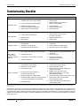
Troubleshooting . . . . . . . . . . . . . . . . . . . . . . . . . . . . . . . . . . .
Unit Control Board Option Setup . . . . . . . . . . . . . . . . . . . . . .
Option Byte Setup . . . . . . . . . . . . . . . . . . . . . . . . . . . . . . .
Heat Delay Setup . . . . . . . . . . . . . . . . . . . . . . . . . . . . . . .
Optional VAV Control Board Flash Codes . . . . . . . . . . . .
43
45
45
45
46
48
48
49
50
51
51
52
54
55
62
62
62
62
LIST OF TABLES
1
2
3
4
5
6
7
8
9
10
11
12
13
14
J15 thru 25 ZJ Unit Limitations . . . . . . . . . . . . . . . . . . . . . 7
Weights and Dimensions . . . . . . . . . . . . . . . . . . . . . . . . . 8
J15 thru 25 ZJ Unit Accessory Weights . . . . . . . . . . . . . . 9
Utilities Entry . . . . . . . . . . . . . . . . . . . . . . . . . . . . . . . . . . . 9
Supply Fan VFD Weights, In Lbs. . . . . . . . . . . . . . . . . . . . 9
J15 thru 25 ZJ Unit Clearances . . . . . . . . . . . . . . . . . . . . 11
Control Wire Sizes . . . . . . . . . . . . . . . . . . . . . . . . . . . . . . 15
Electrical Data . . . . . . . . . . . . . . . . . . . . . . . . . . . . . . . . . 16
J15 thru 25 ZJ Physical Data . . . . . . . . . . . . . . . . . . . . . 25
Electric Heat Minimum Supply Air . . . . . . . . . . . . . . . . . . 26
Gas Application Data . . . . . . . . . . . . . . . . . . . . . . . . . . . 27
Gas Pipe Sizing - CapacIty of Pipe . . . . . . . . . . . . . . . . . 27
Gas Heat Minimum Supply Air . . . . . . . . . . . . . . . . . . . . 27
Altitude/Temperature Correction Factors . . . . . . . . . . . . 35
1
2
3
4
5
6
7
8
9
10
11
J15 thru 25 ZJ Component Location . . . . . . . . . . . . . . . . 6
Unit 4 Point Load Weight . . . . . . . . . . . . . . . . . . . . . . . . . 8
Unit 6 Point Load Weight . . . . . . . . . . . . . . . . . . . . . . . . . 8
Center of Gravity . . . . . . . . . . . . . . . . . . . . . . . . . . . . . . . 8
J15 thru 25 ZJ Unit Dimensions Front View . . . . . . . . . . . 9
J15 thru 25 ZJ Unit Dimensions Rear View . . . . . . . . . . 10
J15 thru 25 ZJ Unit Dimensions Rain Hood . . . . . . . . . . 11
J15 thru 25 ZJ Roof Curb . . . . . . . . . . . . . . . . . . . . . . . . 12
Fixed Outdoor Air Damper . . . . . . . . . . . . . . . . . . . . . . . 13
Condensate Drain . . . . . . . . . . . . . . . . . . . . . . . . . . . . . 13
Field Wiring Disconnect - Cooling Unit With/
Without Electric Heat . . . . . . . . . . . . . . . . . . . . . . . . . . . 14
Typical Field Wiring 24 Volt Thermostat . . . . . . . . . . . . 15
External Supply Connection External Shut-Off . . . . . . . 27
Bottom Supply Connection External Shut-Off . . . . . . . . 27
Vent and Combustion Air Hood . . . . . . . . . . . . . . . . . . . 29
15
16
17
18
19
20
21
22
23
24
25
26
27
Air Flow Performance - Side Duct Application . . . . . . . .
Air Flow Performance - Bottom Duct Application . . . . . .
RPM Selection . . . . . . . . . . . . . . . . . . . . . . . . . . . . . . . .
Indoor Blower Specifications . . . . . . . . . . . . . . . . . . . . . .
Power Exhaust Specifications . . . . . . . . . . . . . . . . . . . . .
Limit Control Setting . . . . . . . . . . . . . . . . . . . . . . . . . . . .
Electric Heat Anticipator Setpoint . . . . . . . . . . . . . . . . . .
Gas Heat Limit Control Setting . . . . . . . . . . . . . . . . . . . .
Gas Heat Anticipator Setpoints . . . . . . . . . . . . . . . . . . . .
Gas Rate Cubic Feet Per Hour . . . . . . . . . . . . . . . . . . . .
Unit Control Board Flash Codes . . . . . . . . . . . . . . . . . . .
Heat Delay . . . . . . . . . . . . . . . . . . . . . . . . . . . . . . . . . . .
VAV Control Board Flash Codes . . . . . . . . . . . . . . . . . .
37
40
43
43
43
48
49
50
51
52
61
62
62
LIST OF FIGURES
12
13
14
15
16
17
18
19
20
21
22
23
24
25
26
27
28
29
30
Enthalpy Set Point Chart . . . . . . . . . . . . . . . . . . . . . . . .
Economizer Control . . . . . . . . . . . . . . . . . . . . . . . . . . . .
Belt Adjustment . . . . . . . . . . . . . . . . . . . . . . . . . . . . . . .
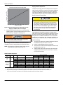
Altitude/Temperature Correction Factors . . . . . . . . . . . .
Pressure Drop Across A Dry Indoor Coil Vs. Supply
Air CFM For All Unit Tonnages . . . . . . . . . . . . . . . . . . .
Gas Valve Piping . . . . . . . . . . . . . . . . . . . . . . . . . . . . . .
Gas Valve and Controls . . . . . . . . . . . . . . . . . . . . . . . . .
Proper Pilot Flame Adjustment . . . . . . . . . . . . . . . . . . .
Typical Flame . . . . . . . . . . . . . . . . . . . . . . . . . . . . . . . . .
Typical Gas Valve . . . . . . . . . . . . . . . . . . . . . . . . . . . . .
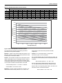
J15ZJ (15 Ton) Charging Chart . . . . . . . . . . . . . . . . . . .
J18ZJ (17.5 Ton) Charging Chart . . . . . . . . . . . . . . . . .
J20ZJ (20 Ton) Charging Chart . . . . . . . . . . . . . . . . . . .
J25ZJ (25 Ton) Charging Chart . . . . . . . . . . . . . . . . . . .
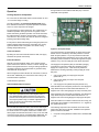
Unit Control Board . . . . . . . . . . . . . . . . . . . . . . . . . . . . .
33
33
34
35
44
50
51
53
53
53
54
54
54
54
61
860261-JIM-B-0612
860261-JIM-B-0612
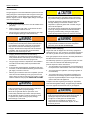
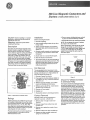
General
Johnson Controls Series 20 J**ZJ models are either single
package air conditioners equipped with optional factory
installed electric heaters, or single package gas-fired central
heating furnaces with cooling unit. Both are designed for
outdoor installation on a rooftop or slab.
The units are completely assembled on rigid, permanently
attached base rails. All piping, refrigerant charge, and electrical
wiring is factory installed and tested. The units require electric
power, gas connection, duct connections, installation of
combustion air inlet hood, flue gas outlet hoods and fixed
outdoor air intake damper (units without economizer or
motorized damper option only) at the point of installation.
The supplemental electric heaters have nickel-chrome
elements and utilize single point power connection.
These gas-fired heaters have aluminized-steel or optional
stainless steel, tubular heat exchangers with spark ignition with
proven pilot. All gas heaters are shipped from the factory equipped
for natural gas use, but can be field converted to L.P./Propane with
Kit Model # 1NP0418. See Gas Heat Application Data Table.
Before performing service or maintenance operations on
unit, turn off main power switch to unit. Electrical shock
could cause personal injury. Improper installation,
adjustment, alteration, service or maintenance can
cause injury or property damage. Refer to this manual.
For assistance or additional information consult a
qualified installer, service agency or the gas supplier.
This system uses R-410A Refrigerant which operates at
higher pressures than R-22. No other refrigerant may be
used in this system. Gage sets, hoses, refrigerant
containers and recovery systems must be designed to
handle R-410A. If you are unsure, consult the equipment
manufacturer. Failure to use R-410A compatible servicing
equipment may result in property damage or injury.
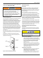
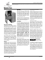
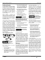
Safety Considerations
This is a safety alert symbol. When you see this symbol on
labels or in manuals, be alert to the potential for personal injury.
Understand and pay particular attention the signal words
DANGER, WARNING or CAUTION.
DANGER indicates an imminently hazardous situation, which,
if not avoided, will result in death or serious injury.
WARNING indicates a potentially hazardous situation, which,
if not avoided, could result in death or serious injury.
CAUTION indicates a potentially hazardous situation, which, if
not avoided may result in minor or moderate injury. It is also
used to alert against unsafe practices and hazards involving
only property damage.
If the information in this manual is not followed exactly, a
fire or explosion may result causing property damage,
personal injury or loss of life.
Do not store or use gasoline or other flammable vapors
and liquids in the vicinity of this or any other appliance.
WHAT TO DO IF YOU SMELL GAS:
a. Do not try to light any appliance.
b. Do not touch any electrical switch; do not use any
phone in your building.
c. Immediately call your gas supplier from a neighbor’s
phone. Follow the gas supplier’s instructions.
d. If you cannot reach your gas supplier, call the fire
department.
Improper installation may create a condition where the
operation of the product could cause personal injury or
property damage. Improper installation, adjustment,
alteration, service or maintenance can cause injury or
property damage. Refer to this manual for assistance or
for additional information, consult a qualified contractor,
installer or service agency.
This product must be installed in strict compliance with
the installation instructions and any applicable local,
state and national codes including, but not limited to
building, electrical, and mechanical codes.
2
Installation and service must be performed by a qualified
installer, service agency or the gas supplier.
Due to system pressure, moving parts, and electrical
components, installation and servicing of air conditioning
equipment can be hazardous. Only qualified, trained service
personnel should install, repair, or service this equipment.
Untrained personnel can perform basic maintenance functions
of cleaning coils and filters and replacing filters.
Observe all precautions in the literature, labels, and tags
accompanying the equipment whenever working on air
conditioning equipment. Be sure to follow all other applicable
safety precautions and codes including ANSI Z223.1 or CSAB149.1- latest edition.
Johnson Controls Unitary Products
860261-JIM-B-0612
Wear safety glasses and work gloves. Use quenching cloth and
have a fire extinguisher available during brazing operations.
Inspection
As soon as a unit is received, it should be inspected for possible
damage during transit. If damage is evident, the extent of the
damage should be noted on the carrier’s freight bill. A separate
request for inspection by the carrier’s agent should be made in
writing.
Renewal Parts
For authorized replacement parts call Johnson Controls, Inc.
National Source 1 Parts outlet at 1-866-523-9670.
Approvals
Design certified by CSA as follows:
1.
For use as a cooling only unit, cooling unit with
supplemental electric heat or a forced air furnace.
2.
For outdoor installation only.
3.
For installation on combustible material.
4.
For use with natural gas (convertible to LP with kit).
This product must be installed in strict compliance with
the enclosed installation instructions and any applicable
local, state and national codes including, but not limited
to, building, electrical, and mechanical codes.
The furnace and its individual shut-off valve must be
disconnected from the gas supply piping system during
any pressure testing at pressures in excess of 1/2 PSIG.
Pressures greater than 1/2 PSIG will cause gas valve
damage resulting in a hazardous condition. If it is
subjected to a pressure greater than 1/2 PSIG, the gas
valve must be replaced.
The furnace must be isolated from the gas supply piping
system by closing its individual manual shut-off valve
during any pressure testing of the gas supply piping
system at test pressures equal to or less than 1/2 PSIG.
This product must be installed in strict compliance with
the enclosed installation instructions and any applicable
local, state, and national codes including, but not limited
to, building, electrical, and mechanical codes.
Improper installation may create a condition where the
operation of the product could cause personal injury or
property damage.
Reference
Additional information is available in the following reference
forms:
• Technical Guide - J15 thru 25 ZJ/ZR/ZF, 349690
• General Installation - J15 thru 25 ZJ, 860261
Johnson Controls Unitary Products
This system uses R-410A Refrigerant which operates at
higher pressures than R-22. No other refrigerant may be
used in this system.
3
860261-JIM-B-0612
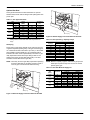
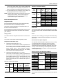
Nomenclature
15-25 Ton Series 20 Model Number Nomenclature
J15 Z J N24 A 2 A AA 1 0 1 2 4 A
Nominal Cooling Capacity
Product Style
J15 = 15 Ton
J18 = 17.5 Ton
J20 = 20 Ton
J25 = 25 Ton
A = Style A
Configuration Options (not required for all units)
These four digits will not be assigned until a quote is requested, or an order placed.
SS Drain Pan
Product Category
Johnson UNT 1126 Controller (N2 protocol), DFS, APS
Z = A/C, Single Pkg., R-410A
Johnson Commercial Controls System (CCS) Rtu Controller
Johnson Controller Metasys FEC-2611 (BACnet MS/TP Protocol), SAS, RAS, OAS, DFS, APS
CPC Controller, DFS, APS
Product Identifier
Honeywell Controller, DFS, APS
J = 11.0+ EER A/C
Novar Controller, DFS, APS
Simplicity IntelliComfort II Controller
Heat Type and Nominal Heat Capacity
Simplicity IntelliComfort II Controller w/Simplicity™LINC
Hot Gas Bypass (Standard on VAV, Optional on CV)
C00 = Cooling Only. No field installed
electric heat
Variable Air Volume, VFD
Variable Air Volume, VFD and Manual Bypass
Variable Air Volume, VFD (BAS ready - for customer provided VFD controller)
Gas Heat Options
Variable Air Volume, VFD and Manual Bypass (BAS ready)
N24 = 240 MBH Output Aluminized Steel
N32 = 320 MBH Output Aluminized Steel
S24 = 240 MBH Output Stainless Steel
S32 = 320 MBH Output Stainless Steel
Variable Air Volume, VFD Ready (for customer provided, field installed drive)
2" Pleated Filters, MERV 7
4" Pleated Filters, MERV 13
BAS Ready Economizer (2-10 V.D.C. Actuator without a controller)
Double Wall Construction
Electric Heat Options
For valid combinations of the above; see the equipment price pages or
the Unitary Sales Tool program; all combinations are not available
E18 = 18 KW
E36 = 36 KW
E54 = 54 KW
E72 = 72 KW
Product Generation
1 = First Generation
Airflow
A = Std. Motor
B = Std. Motor/Economizer
C = Std. Motor/Economizer/Power Exhaust
(Downflow Only)
D = Std. Motor/Motorized Damper
E = Std. Motor/Motorized Damper/Barometric Relief
J = Std. Motor/Economizer/Barometric Relief
N = Hi Static
P = Hi Static/Economizer
Q = Hi Static/Economizer/Power Exhaust
(Downflow Only)
R = Hi Static/Motorized Damper
K = Hi Static/Motorized Damper/Barometric Relief
S = Hi Static/Economizer/Barometric Relief
2 = Low Static
3 = Low Static/Economizer
4 = Low Static/Economizer/Power Exhaust
(Downflow Only)
5 = Low Static/Motorized Damper
6 = Low Static/Motorized Damper/Barometric Relief
7 = Low Static/Economizer/Barometric Relief
Additional Options
Standard Cabinet
Hinged Filter Door & Tool Free Access Cabinet
AA = None
AB = Phase Monitor
AC = Coil Guard
AD = Dirty Filter Switch
AE = Phase Monitor & Coil Guard
AF = Phase Monitor & Dirty Filter Switch
AG = Coil Guard & Dirty Filter Switch
AH = Phase Monitor, Coil Guard & Dirty Filter Switch
RC = Coil Guard & American Flag
TA = Technicoat Condenser Coil
TJ = Technicoat Evaporator Coil
TS = Technicoat Evaporator & Condenser Coils
EA = ElectroFin Condenser Coil
EJ = ElectroFin Evaporator Coil
ES = ElectroFin Cond & Evap Coils
BA = Hinged Filter Door & Tool Free Access Panels
BB = Phase Monitor, Hinged Filter Door & Tool Free
Access Panels
BC = Coil Guard, Hinged Filter Door & Tool Free
Access Panels
BD = Dirty Filter Switch, Hinged Filter Door &
Tool Free Access Panels
BE = Phase Monitor & Coil Guard, Hinged Filter
Door & Tool Free Access Panels
BF = Phase Monitor & Dirty Filter Switch, Hinged
Filter Door & Tool Free Access Panels
BG = Coil Guard & Dirty Filter Switch, Hinged Filter
Door & Tool Free Access Panels
BH = Phase Monitor, Coil Guard & Dirty Filter Switch,
Hinged Filter Door & Tool Free Access Panels
ZZ = If desired option combination is not listed above, ZZ will be assigned and configuration options will be
located in digits 15-18.
Voltage
2 = 208/230-3-60
4 = 460-3-60
5 = 575-3-60
Installation Options
A = No Options Installed
B = Option 1
C = Option 2
D = Options 1 & 2
E = Option 3
F = Option 4
G = Options 1 & 3
H = Options 1 & 4
J = Options 1, 2 & 3
K = Options 1, 2, & 4
L = Options 1,3 & 4
M = Options 1, 2, 3, & 4
N = Options 2 & 3
P = Options 2 & 4
Q = Options 2, 3, & 4
R = Options 3 & 4
S = Option 5
T = Options 1 & 5
U = Options 1, 3, & 5
V = Options 1, 4, & 5
W = Options 1, 3, 4, & 5
X = Options 3 & 5
Y = Options 4 & 5
Z = Options 3, 4 & 5
Options
1 = Disconnect
2 = Non-Pwr'd Conv. Outlet
3 = Smoke Detector S.A.
4
4 = Smoke Detector R.A.
5 = Pwr'd Conv. Outlet
Johnson Controls Unitary Products
860261-JIM-B-0612
Installation
Installation Safety Information
Read these instructions before continuing this appliance
installation. This is an outdoor combination heating and cooling
unit. The installer must assure that these instructions are made
available to the consumer and with instructions to retain them
for future reference.
1.
Refer to the unit rating plate for the approved type of gas
for this product.
2.
Install this unit only in a location and position as specified
on Page 7 of these instructions.
3.
4.
5.
Limitations
These units must be installed in accordance with the following:
In U.S.A.:
1.
National Electrical Code, ANSI/NFPA No. 70 - Latest
Edition
2.
National Fuel Gas Code, ANSI Z223.1 - Latest Edition
3.
Gas-Fired Central Furnace Standard, ANSI Z21.47a. Latest Edition
4.
Local building codes, and
5.
Local gas utility requirements
Never test for gas leaks with an open flame. Use
commercially available soap solution made specifically for
the detection of leaks when checking all connections, as
specified on Pages 5, 28 and 52 of these instructions.
In Canada:
Always install furnace to operate within the furnace's
intended temperature-rise range with the duct system
and within the allowable external static pressure range,
as specified on the unit name/rating plate, specified on
Page 27 of these instructions.
This equipment is not to be used for temporary heating of
buildings or structures under construction.
1.
Canadian Electrical Code, CSA C22.1
2.
Installation Codes, CSA - B149.1.
3.
Local plumbing and waste water codes, and
4.
Other applicable local codes.
Refer to unit application data found in this document.
After installation, gas fired units must be adjusted to obtain a
temperature rise within the range specified on the unit rating
plate.
If components are to be added to a unit to meet local codes,
they are to be installed at the dealer’s and/or customer’s
expense.
FIRE OR EXPLOSION HAZARD
Failure to follow the safety warning exactly could result
in serious injury, death or property damage.
Never test for gas leaks with an open flame. use a
commercially available soap solution made specifically
for the detection of leaks to check all connections. A fire
or explosion may result causing property damage,
personal injury or loss of life.
6.
If a factory option convenience outlet is installed, the
weatherproof outlet cover must be field installed. The cover
shall be located in the unit control box. To install the cover,
remove the shipping label covering the convenience outlet,
follow the instructions on the back of the weatherproof
cover box, and attach the cover to the unit using the (4)
screws provided.
Size of unit for proposed installation should be based on heat
loss/heat gain calculation made according to the methods of Air
Conditioning Contractors of America (ACCA).
This furnace is not to be used for temporary heating of buildings
or structures under construction.
.
The control board used in this product will effectively
operate the cooling system down to 0°F when this
product is applied in a comfort cooling application for
people. An economizer is typically included in this type
of application. When applying this product for process
cooling applications (computer rooms, switchgear, etc.),
please reference applications bulletin AE-011-07 or call
the applications department for Unitary Products @ 1877-UPG-SERV for guidance. Additional accessories
may be needed for stable operation at temperatures
below 30°F.
208/230-3-60 and 380/415-3-50 units with factory
installed Powered Convenience Outlet Option are wired
for 230v and 415v power supply respectively. Change
tap on transformer for 208-3-60 or 380-3-50 operation.
See unit wiring diagram.
Johnson Controls Unitary Products
5
860261-JIM-B-0612
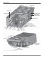
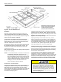
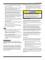
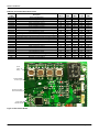
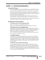
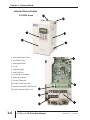
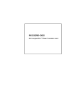
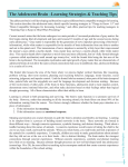
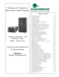
Unit Control Board
Slide In/ Plug In
Internal Economizer
(Optional)
110 Volt Convenience
Outlet (“Powered” or
“Non-Powered” Optional)
2” Disposable Filters
(4” Filters Optional)
Disconnect Location
(Optional Disconnect Switch)
Bottom Power and
Control Wiring Entry
Power Ventor Motor
Electric Heater Location
(Optional Electric/Electric Units)
Location of VFD (Optional)
Location of VFD Bypass (Optional)
Belt Drive
Blower Motor
Copper Tube/
Aluminum Fin Thermal
1” NPT
Evaporator Expansion
Valve
Condensate Drain
Coils
Filter Drier
(Solid Core)
14 Gauge
Base Rails
with Lifting Holes
Outdoor Fan #2
Outdoor Fan #1
Outdoor Fan #4
Outdoor Fan #3
Copper Tube/Aluminum Fin
Condenser Coils
Compressor #4
Compressor #3
Compressor #2 Compressor #1
High Efficiency Scroll Compressors
Figure 1: J15 thru 25 ZJ Component Location
6
Johnson Controls Unitary Products
860261-JIM-B-0612
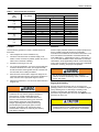
Table 1: J15 thru 25 ZJ Unit Limitations
Unit Limitations
Size
(Tons)
J15
(15)
J18
(17.5)
J20
(20)
J25
(25)
Unit Voltage
Applied Voltage
Outdoor DB Temp
Min
Max
Max (°F)
208/230-3-60
187
252
125
460-3-60
432
504
125
575-3-60
540
630
125
208/230-3-60
187
252
125
460-3-60
432
504
125
575-3-60
540
630
125
208/230-3-60
187
252
125
460-3-60
432
504
125
575-3-60
540
630
125
208/230-3-60
187
252
125
460-3-60
432
504
125
575-3-60
540
630
125
Location
Clearances
Use the following guidelines to select a suitable location for
these units:
All units require particular clearances for proper operation and
service. Installer must make provisions for adequate
combustion and ventilation air in accordance with section 5.3 of
Air for Combustion and Ventilation of the National Fuel Gas
Code, ANSI Z223.1 – Latest Edition (in U.S.A.), or Sections 7.2,
7.3, or 7.4 of Gas Installation Codes, CSA-B149.1 (in Canada) Latest Edition, and/or applicable provisions of the local building
codes. Refer to Table 6 for clearances required for combustible
construction, servicing, and proper unit operation.
1.
Unit is designed for outdoor installation only.
2.
Condenser coils must have an unlimited supply of air.
Where a choice of location is possible, position the unit on
either north or east side of building.
3.
Suitable for mounting on roof curb.
4.
For ground level installation, use a level concrete slab with
a minimum thickness of 4 inches. The length and width
should be at least 6 inches greater than the unit base rails.
Do not tie slab to the building foundation.
5.
Roof structures must be able to support the weight of the
unit and its options/accessories. Unit must be installed on a
solid, level roof curb or appropriate angle iron frame.
6.
Maintain level tolerance to 1/2” across the entire width and
length of unit.
Excessive exposure of this furnace to contaminated
combustion air may result in equipment damage or
personal injury. Typical contaminates include:
permanent wave solution, chlorinated waxes and
cleaners, chlorine based swimming pool chemicals,
water softening chemicals, carbon tetrachloride,
Halogen type refrigerants, cleaning solvents (e.g.
perchloroethylene), printing inks, paint removers,
varnishes, hydrochloric acid, cements and glues,
antistatic fabric softeners for clothes dryers, masonry
acid washing materials.
Johnson Controls Unitary Products
Do not permit overhanging structures or shrubs to
obstruct condenser air discharge outlet, combustion air
inlet or vent outlets.
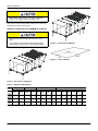
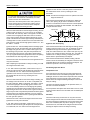
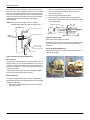
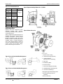
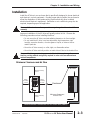
Rigging And Handling
Exercise care when moving the unit. Do not remove any
packaging until the unit is near the place of installation. Rig the
unit by attaching chain or cable slings to the lifting holes
provided in the base rails. Spreader bars, whose length
exceeds the largest dimension across the unit, MUST be used
across the top of the unit.
If a unit is to be installed on a roof curb other than a
Unitary Products roof curb, gasketing must be applied to
all surfaces that come in contact with the unit underside.
7
860261-JIM-B-0612
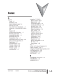
Before lifting, make sure the unit weight is distributed
equally on the rigging cables so it will lift evenly.
Units may be moved or lifted with a forklift, from the side only,
providing an accessory skid is used.
C
LENGTH OF FORKS MUST BE A MINIMUM OF 90 INCHES.
B
E
D
A
All panels must be secured in place when the unit is
lifted.
F
The condenser coils should be protected from rigging
cable damage with plywood or other suitable material.
Figure 3: Unit 6 Point Load Weight
Y
X
FRONT
LEFT
Figure 4: Center of Gravity
B
C
A
D
Figure 2: Unit 4 Point Load Weight
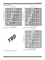
Table 2: Weights and Dimensions
Weight (lbs.)
Center of Gravity
Size
(Tons) Shipping Operating
X
Y
J15ZJ
2614
2609
85.25
44
(15)
J18ZJ
TBD
TBD
TBD
TBD
(17.5)
J20ZJ
2702
2697
85.05
44
(20)
J25ZJ
2788
2783
85.25
44
(25)
8
4 Point Load Location (lbs.)
A
B
C
D
A
6 Point Load Location (lbs.)
B
C
D
E
F
467
781
852
510
287
392
568
620
428
313
TBD
TBD
TBD
TBD
TBD
TBD
TBD
TBD
TBD
TBD
485
805
878
529
298
406
585
638
443
326
498
833
908
544
306
419
606
661
457
334
Johnson Controls Unitary Products
860261-JIM-B-0612
Table 3: J15 thru 25 ZJ Unit Accessory Weights
Weight (lbs.)
Unit Accessory
Shipping
165
90
40
240
260
150
50
60
95
220
190
10
Economizer
Power Exhaust
Electric Heat1
Gas Heat2
Double Wall
Motorized Damper
Barometric Damper
Econ./Motorized Damper Rain Hood
Econ./Power Exhaust Rain Hood
Wood Skid
Roof Curb
Hot Gas Bypass
Supply Fan VFD
Operating
160
85
40
240
260
150
45
55
90
220
185
10
See Table 5
1. Weight given is for the maximum heater size available (54KW).
2. Weight given is for the maximum number of tube heat exchangers available (8 tube).
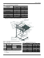
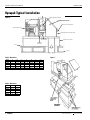
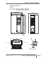
ECONOMIZER / MOTORIZED DAMPER
FIXED OUTDOOR INTAKE AIR AND
POWER EXHAUST RAIN HOODS
(See detail Y)
BLOWER MOTOR
ACCESS (Location
of Optional VFD Bypass)
BLOWER
COMPARTMENT
ACCESS
(Auxiliary)
DOT PLUG
(For pressure
drop reading)
BLOWER ACCESS
(Location of
Optional VFD)
COMPRESSOR ACCESS
180-19/32
52-5/8
GAS OR ELECTRIC
HEAT
ACCESS
COIL
GUARD
KIT
VENT AIR
OUTLET
HOODS
COMBUSTION
AIR INLET HOOD
21.00
(C) GAS
SUPPLY
ENTRY
9-3/4
CONDENSER
COILS
7-1/8
136-1/4
(A) CONTROL WIRING
ENTRY
92
6-3/8
5
DISCONNECT
SWITCH
LOCATION
46-5/8
11-1/2
CONTROL BOX
ACCESS
5-7/8
(B) POWER
WIRING
ENTRY
35
BOTTOM SUPPLY
AND RETURN
AIR OPENINGS
(See Note)
35-1/4
33
2-3/4
RETURN
AIR
SUPPLY
AIR
3-3/4
21-1/2
UNIT BASE RAILS
Shown separately to illustrate
Bottom Duct openings. Power
and Gas Piping Connection
location.
(D)
GAS SUPPLY
ENTRY
(B) POWER WIRING
ENTRY
11-1/8
NOTE:
For curb mounted units, refer to the curb hanger
dimensions of the curb for proper size of the
supply and return air duct connections.
8-1/8
12-1/2
(A) CONTROL WIRING
ENTRY
46-5/8
9-1/4
9-3/4
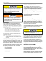
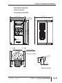
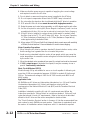
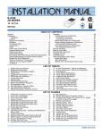
Figure 5: J15 thru 25 ZJ Unit Dimensions Front View
Table 5: Supply Fan VFD Weights, In Lbs.
Table 4: Utilities Entry
Hole
A
B
C
D
Opening Size
Diameter
1-1/8” KO
3/4” NPS (Fem.)
3-5/8” KO
3” NPS (Fem.)
2-3/8” KO
1-11/16” Hole
Used For
Front
Bottom
Front
Power Wiring
Bottom
Gas Piping (Front)1
Gas Piping (Bottom)1,2
Control Wiring
1. One-inch Gas Piping NPT Required.
2. Opening in the bottom to the unit can be located by the slice in the
insulation.
230V
460V
575V
W/O Manual Bypass
5.0 hp
7.5 hp
10.0 hp
15.0 hp
Supply Fan Motor
25
30
30
30
25
30
30
30
30
30
35
40
W/Manual Bypass
5.0 hp
7.5 hp
10.0 hp
15.0 hp
30
35
35
40
30
35
35
35
35
35
40
45
Note: All entry holes should be sealed to prevent rain water entry
into building.
Johnson Controls Unitary Products
9
860261-JIM-B-0612
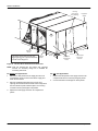
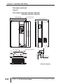
Dot Plug
(for Pressure
Drop Reading)
Evaporator
Section
40-3/8”
Supply
Air
Outdoor
Air
Return
Air
18-5/8”
Supply Air
Access
40-1/2”
27-3/4”
Filter
Access
5-1/8”
Dimensions listed are for side duct
flange opening; see Field Accessories
for Side Duct Flange Kit.
39-5/8”
Return Air
Access
Outdoor Air
Compartment
Access
1” NPT Female
Cond. Drain
Connector
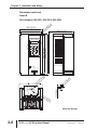
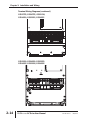
Figure 6: J15 thru 25 ZJ Unit Dimensions Rear View
NOTE: Units are shipped with the bottom duct openings
covered. An accessory flange kit is available for
connecting side ducts.
For bottom duct applications:
For side duct applications:
1.
Remove the side panels from the supply and return air
compartments to gain access to the bottom supply and
return air duct covers.
1.
Replace the side panels on the supply and return air
compartments with the accessory flange kit panels.
2.
Connect ductwork to the flanges on those panels.
2.
Remove and discard the bottom duct covers. Duct
openings are closed with sheet metal covers except when
the unit includes a power exhaust option. The covering
consists of a heavy black paper composition.
3.
Replace the side supply and return air compartment
panels.
10
Johnson Controls Unitary Products
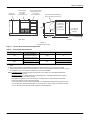
860261-JIM-B-0612
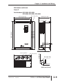
Supply Air
Compartment
Power Exhaust
Rain Hood
(on Return
Air Compartment)
Economizer Motorized
Damper Rain Hood
(on Outdoor
Air Compartment)
Economizer/Motorized Damper
and Power Exhaust Rain Hood
Fixed
Outdoor Air
Intake Hood
(Located on
Return Air
Compartment)
36-5/8”
1” Condensate
Drain (Must be
Trapped)
16-1/8”
5”
28-3/16”
92”
Rear View
LH View
Detail “Y”
Unit with Rain Hoods
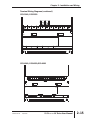
Figure 7: J15 thru 25 ZJ Unit Dimensions Rain Hood
Table 6: J15 thru 25 ZJ Unit Clearances
Direction
Top1
Front
Rear
Distance (in.)
72 With 36 Maximum
Horizontal Overhang (For
Condenser Air Discharge)
36
24 (W/O Economizer)
49 (W/Economizer)
Direction
Distance (in.)
Right
36
Bottom2
0
24 (W/O Economizer)
36 (W/Economizer)3
Left
1. Units must be installed outdoors. Over hanging structure or shrubs should not obscure condenser air discharge
outlet.
2. Units may be installed on combustable floors made from wood or class A, B or C roof covering materials.
3. If economizer is factory installed, the unassembled rain hood must be removed from its ride along position in front of
the evaporator coil, or in the outdoor air compartment, prior to final installation.
Note: ELEC/ELEC Models: Units and ductwork are approved for zero clearance to combustible material when
equipped with electric heaters.
GAS/ELEC Models: A 1" clearance must be provided between any combustible material and the supply air
ductwork for a distance of 3 feet from the unit.
The products of combustion must not be allowed to accumulate within a confined space and recirculate.
Locate unit so that the vent air outlet hood is at least:
• Three (3) feet above any force air inlet located within 10 horizontal feet (excluding those integral to the unit).
• Four (4) feet below, four horizontal feet from, or one foot above any door or gravity air inlet into the building.
• Four (4) feet from electric and gas meters, regulators and relief equipment.
Johnson Controls Unitary Products
11
860261-JIM-B-0612
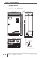
25-1/4"
Figure 8: J15 thru 25 ZJ Roof Curb
Ductwork
Ductwork should be designed and sized according to the
methods in Manual D of the Air Conditioning Contractors of
America (ACCA) or as recommended by any other recognized
authority such as ASHRAE or SMACNA.
A closed return duct system should be used. This will not
preclude use of economizers or outdoor fresh air intake. The
supply and return air duct connections at the unit should be
made with flexible joints to minimize noise.
The supply and return air duct systems should be designed for
the CFM and static pressure requirements of the job. They
should NOT be sized to match the dimensions of the duct
connections on the unit.
Refer to Figure 5 for bottom air duct openings. Refer to Figure 6
for side air duct openings.
NOTE: It is recommended that, in Canada, the outlet duct be
provided with a removable access panel. It is
recommended that this opening be accessible when
the unit is installed in service, and of a size such that
smoke or reflected light may be observed inside the
casing to indicate the presence of leaks in the heat
exchanger. The cover should be attached in a
manner adequate to prevent leakage.
Gasketing and mounting screws are provided in a parts bag
attached to the hood assembly. Apply gasketing to the three
flange surfaces on the hood prior to installing the hood. Extend
gasketing 1/4 inch beyond the top and bottom of the two side
flanges to insure adequate sealing.
Adjusting the damper to the desired air flow may be done
before mounting the hood into position or after installation by
removing the front hood panel or the screen on the bottom of
the hood. Damper baffle in position 1 will allow approximately
10% outdoor air flow, position 2 approximately 15% and, to
allow approximately 25%, remove the damper baffle.
On units with bottom return air application install the damper
assembly over the opening in the side return air access panel.
Remove and discard the opening cover and the covering over
the hood mounting holes (used for shipping) before installing.
Secure with the screws provided.
On units with side return air applications, install the damper
assembly on the return air ductwork as close to the unit as
possible. Cut an opening 16 inches high by 18 inches wide in the
ductwork to accommodate the damper. Using the holes in the
hood flanges as a template, drill 9/64 inch diameter (#26 drill)
holes into the ductwork and secure with the screws provided.
Fixed Outdoor Air Intake Damper
This damper is shipped inside the return air compartment. It is
completely assembled and ready for installation. A damper
baffle inside of the hood is adjustable to provide variable
amounts of outdoor air intake on units that are not provided with
an economizer or a motorized damper option. Refer to the
Fixed Outdoor Damper Figure 9.
12
If outdoor air intake will not be required on units with
bottom return air applications, the damper assembly
should still be mounted on the side return air access
panel, per the instructions above, to insure moisture is
not drawn into the unit during operation. The covering
over the mounting holes only need be removed. Do not
remove the opening cover.
Johnson Controls Unitary Products
860261-JIM-B-0612
The compressor also uses a polyolester (POE oil), Mobil 3MA
POE. This oil is extremely hygroscopic, meaning it absorbs water
readily. POE oil can absorb 15 times as much water as other oils
designed for HCFC and CFC refrigerants. Take all necessary
precautions to avoid exposure of the oil to the atmosphere.
Side Supply
Air Access
Panel
*
Damper
Baffle
Hood
Screen
Do not leave the system open to the atmosphere. Unit
damage could occur due to moisture being absorbed by
the POE oil in the system. This type of oil is highly
susceptible to moisture absorption
Side Return Air
Access Panel
Outdoor Air
Opening Cover
Rear View
1
2
* Gasketed
Flange
POE (polyolester) compressor lubricants are known to cause
long term damage to some synthetic roofing materials.
Figure 9: Fixed Outdoor Air Damper
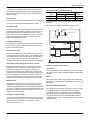
Condensate Drain
Plumbing must conform to local codes. Use a sealing compound
on male pipe threads. Install a condensate drain line from the
one-inch NPT female connection on the unit to an open drain.
NOTE: The condensate drain operates in a negative pressure
in the cabinet. The condensate drain line MUST be
trapped to provide proper drainage. See Figure 10.
Base
Pan
Unit Condensate
Connection
Exposure, even if immediately cleaned up, may cause
embrittlement (leading to cracking) to occur in one year
or more. When performing any service that may risk
exposure of compressor oil to the roof, take precautions
to protect roofing.
Procedures which risk oil leakage include, but are not limited to,
compressor replacement, repairing refrigerant leaks, replacing
refrigerant components such as filter drier, pressure switch,
metering device or coil.
Units are shipped with compressor mountings which are
factory-adjusted and ready for operation.
3” Min.
2”
Base
Rails
Drain
Plug
Do not loosen compressor mounting bolts.
Figure 10: Condensate Drain
Filters
Compressors
Two-inch filters are supplied with each unit, but units can be
converted easily to four-inch filters. Filters must always be
installed ahead of the evaporator coil and must be kept clean or
replaced with same size and type. Dirty filters will reduce the
capacity of the unit and will result in frosted coils or safety
shutdown. Minimum filter area and required sizes are shown in
Physical Data Table 9.
The scroll compressor used in this product is specifically
designed to operate with R-410A Refrigerant and cannot be
interchanged.
This system uses R-410A Refrigerant which operates at
higher pressures than R-22. No other refrigerant may be
used in this system.
Johnson Controls Unitary Products
Make sure that panel latches are properly positioned on
the unit to maintain an airtight seal.
13
860261-JIM-B-0612
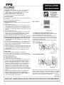
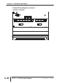
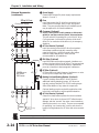
Power And Control Wiring
Field wiring to the unit, fuses, and disconnects must conform to
provisions of National Electrical Code (NEC), ANSI/NFPA No.
70 – Latest Edition (in U.S.A.), current Canadian Electrical
Code C221, and/or local ordinances. The unit must be
electrically grounded in accordance with NEC and CEC as
specified above and/or local codes.
208/230-3-60 and 380/415-3-50 units control
transformers are factory wired for 230v and 415v power
supply respectively. Change tap on transformer for 2083-60 or 380-3-50 operation. See unit wiring diagram.
Voltage tolerances which must be maintained at the
compressor terminals during starting and running conditions are
indicated on the unit Rating Plate and Table 1.
The internal wiring harnesses furnished with this unit are an
integral part of the design certified unit. Field alteration to
comply with electrical codes should not be required. If any of
the wire supplied with the unit must be replaced, replacement
wire must be of the type shown on the wiring diagram and the
same minimum gauge as the replaced wire.
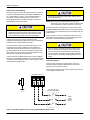
A disconnect must be utilized for these units. Factory installed
disconnects are available. If installing a disconnect (field supplied
or Unitary Products supplied accessory), refer to Figure 1 for the
recommended mounting location.
Avoid damage to internal components if drilling holes for
disconnect mounting.
NOTE: Since not all local codes allow the mounting of a
disconnect on the unit, please confirm compliance with
local code before mounting a disconnect on the unit.
Electrical line must be sized properly to carry the load. USE
COPPER CONDUCTORS ONLY. Each unit must be wired with
a separate branch circuit fed directly from the meter panel and
properly fused.
Refer to Figures 11 and 12 for typical field wiring and to the
appropriate unit wiring diagram mounted inside control doors
for control circuit and power wiring information.
When connecting electrical power and control wiring to
the unit, water-proof connectors must be used so that
water or moisture cannot be drawn into the unit during
normal operation. The above water-proofing conditions
will also apply when installing a field supplied disconnect
switch.
Power Wiring Detail
Units are factory wired for the voltage shown on the unit
nameplate. Refer to Electrical Data Table 8 to size power
wiring, fuses, and disconnect switch.
Power wiring is brought into the unit through the side of the unit
or the basepan inside the curb.
TERMINAL BLOCK TB1
GROUND
LUG
FACTORY OR FIELD
SUPPLIED DISCONNECT
THREE
PHASE
POWER
SUPPLY
Figure 11: Field Wiring Disconnect - Cooling Unit With/Without Electric Heat
14
Johnson Controls Unitary Products
860261-JIM-B-0612
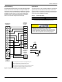
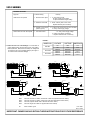
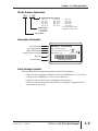
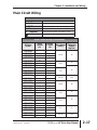
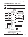
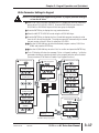
Thermostat Wiring
Space Sensor
The thermostat should be located on an inside wall approximately
56 inch above the floor where it will not be subject to drafts, sun
exposure or heat from electrical fixtures or appliances. Follow the
manufacturer's instructions enclosed with thermostat for general
installation procedure. Seven (7) color-coded, insulated wires
should be used to connect the thermostat to the unit. Refer to
Table 7 for control wire sizing and maximum length.
The space sensor, if used, should be located on an inside wall
approximately 56 inches above the floor where it will not be
subject to drafts, sun exposure or heat from electrical fixtures or
appliances. Follow manufacturer's instructions enclosed with
sensor for general installation procedure.
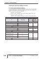
Table 7: Control Wire Sizes
Wire Size
18 AWG
Maximum Length1
150 Feet
1. From the unit to the thermostat and back to the unit.
CONTROL
TERMINAL
BLOCK
THERMOSTAT
TERMINALS
W1
W1
W2
208/230-3-60 and 380/415-3-50 units control
transformers are factory wired for 230v and 415v power
supply respectively. Change tap on transformer for 2083-60 or 380-3-50 operation. See unit wiring diagram.
W2
Y1
1
G
Y1
OCC
Y2
P
Y3
P1
Y4
Y2
X
G
Smoke
Detector
R
R
SD
C
C
R
Jumper
2
SD
EXPANSION
BOARD
TERMINAL
BLOCK
3
RC
4
OCC
X
SD
C
24 VAC
Class 2
Y3
5
Y4
TERMINALS ON
A LIMITED
NUMBER OF
THERMOSTATS
1
Second stage heating not required on single stage heating units.
2
Jumper is required if there is no Smoke Detector circuit.
3
Jumper is required for any combination of R, RC, or RH.
4
OCC is an output from the thermostat to indicate the Occupied condition.
5
X is an input to the thermostat to display Error Status conditions.
Figure 12: Typical Field Wiring 24 Volt Thermostat
Johnson Controls Unitary Products
15
860261-JIM-B-0612
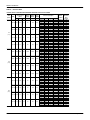
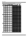
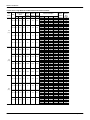
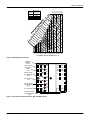
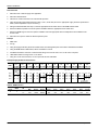
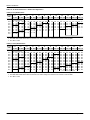
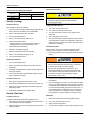
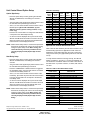
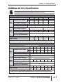
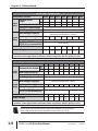
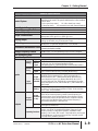
Table 8: Electrical Data
J15 thru 25 ZJ - Standard Drive Without Powered Convenience Outlet
Size
(Tons)
Volt
Compressors
(each)
RLA LRA
MCC
OD Fan
Motors
(each)
FLA
Supply
Blower
Motor
FLA
Pwr
Conv
Outlet
FLA
208-3-60 13.1
83
20.5
2.1
15.4
0.0
230-3-60 13.1
83
20.5
2.1
14.4
0.0
460-3-60 6.1
41
9.5
1.1
7.2
0.0
575-3-60 4.4
33
6.8
0.9
5.9
0.0
J15
(15)
TBD
TBD
TBD
TBD
TBD
TBD
TBD
TBD
TBD
TBD
TBD
TBD
TBD
TBD
TBD
TBD
TBD
TBD
TBD
TBD
TBD
TBD
TBD
TBD
TBD
TBD
TBD
TBD
208-3-60 17.9
120
28.0
3.7
15.4
0.0
230-3-60 17.9
120
28.0
3.7
14.4
0.0
460-3-60 9.6
70
15.0
1.9
7.2
0.0
575-3-60 7.4
53
11.5
1.5
5.9
0.0
J18
(17.5)
J20
(20)
16
MCA1
(Amps)
Electric Heat Option
Model
None
E18
E36
E54
E72
None
E18
E36
E54
E72
None
E18
E36
E54
E72
None
E18
E36
E54
E72
TBD
TBD
TBD
TBD
TBD
TBD
TBD
TBD
TBD
TBD
TBD
TBD
TBD
TBD
TBD
TBD
TBD
TBD
TBD
TBD
None
E18
E36
E54
E72
None
E18
E36
E54
E72
None
E18
E36
E54
E72
None
E18
E36
E54
E72
kW
-13.5
27
40.6
54.1
-18.0
36.0
54.0
72.0
-18.0
36.0
54.0
72.0
-18.0
36.0
54.0
72.0
TBD
TBD
TBD
TBD
TBD
TBD
TBD
TBD
TBD
TBD
TBD
TBD
TBD
TBD
TBD
TBD
TBD
TBD
TBD
TBD
13.5
27.0
40.6
54.1
18.0
36.0
54.0
72.0
18.0
36.0
54.0
72.0
18.0
36.0
54.0
72.0
Stages
-1
2
2
2
-1
2
2
2
-1
2
2
2
-1
2
2
2
TBD
TBD
TBD
TBD
TBD
TBD
TBD
TBD
TBD
TBD
TBD
TBD
TBD
TBD
TBD
TBD
TBD
TBD
TBD
TBD
1
2
2
2
1
2
2
2
1
2
2
2
1
2
2
2
Amps
-37.5
74.9
112.7
150.2
-43.3
86.6
129.9
173.2
-21.7
43.3
65.0
86.6
-17.3
34.6
52.0
69.3
TBD
TBD
TBD
TBD
TBD
TBD
TBD
TBD
TBD
TBD
TBD
TBD
TBD
TBD
TBD
TBD
TBD
TBD
TBD
TBD
37.5
74.9
112.7
150.2
43.3
86.6
129.9
173.2
21.7
43.3
65.0
86.6
17.3
34.6
52.0
69.3
80.1
80.1
112.9
160.1
169.4
78.8
78.8
126.3
147.9
191.2
37.8
37.8
63.1
74.0
95.6
28.6
29.0
50.7
59.3
76.7
TBD
TBD
TBD
TBD
TBD
TBD
TBD
TBD
TBD
TBD
TBD
TBD
TBD
TBD
TBD
TBD
TBD
TBD
TBD
TBD
106.3
106.3
112.9
160.1
169.4
105.3
105.3
126.3
147.9
191.2
55.6
55.6
63.1
74.0
95.6
43.4
43.4
50.7
59.3
76.7
Max Fuse2/
Breaker3
Size
(Amps)
90
90
125
175
200
90
90
150
175
225
45
45
70
90
110
30
30
60
70
90
TBD
TBD
TBD
TBD
TBD
TBD
TBD
TBD
TBD
TBD
TBD
TBD
TBD
TBD
TBD
TBD
TBD
TBD
TBD
TBD
110
110
125
175
200
110
110
150
175
225
60
60
70
90
110
50
50
60
70
90
Johnson Controls Unitary Products
860261-JIM-B-0612
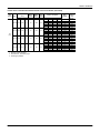
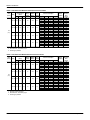
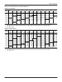
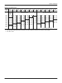
J15 thru 25 ZJ - Standard Drive Without Powered Convenience Outlet (Continued)
Size
(Tons)
Volt
Compressors
(each)
RLA LRA
MCC
OD Fan
Motors
(each)
FLA
Supply
Blower
Motor
FLA
Pwr
Conv
Outlet
FLA
208-3-60 22.4
149
35.0
3.7
28.0
0.0
230-3-60 22.4
149
35.0
3.7
26.0
0.0
460-3-60 10.6
75
16.5
1.9
13.0
0.0
575-3-60 7.7
54
12.0
1.5
10.3
0.0
J25
(25)
MCA1
(Amps)
Electric Heat Option
Model
None
E18
E36
E54
E72
None
E18
E36
E54
E72
None
E18
E36
E54
E72
None
E18
E36
E54
E72
kW
-13.5
27.0
40.6
54.1
-18.0
36.0
54.0
72.0
-18.0
36.0
54.0
72.0
-18.0
36.0
54.0
72.0
Stages
-1
2
2
2
-1
2
2
2
-1
2
2
2
-1
2
2
2
Amps
-37.5
74.9
112.7
150.2
-43.3
86.6
129.9
173.2
-21.7
43.3
65.0
86.6
-17.3
34.6
52.0
69.3
139.4
139.4
139.4
175.9
185.2
136.9
136.9
140.8
162.4
205.7
66.3
66.3
70.4
81.2
102.9
49.7
49.7
56.2
64.8
82.2
Max Fuse2/
Breaker3
Size
(Amps)
150
150
150
200
200
150
150
150
175
225
70
70
80
90
110
50
50
60
70
90
1. Minimum Circuit Ampacity.
2. Dual Element, Time Delay Type.
3. HACR type per NEC.
Johnson Controls Unitary Products
17
860261-JIM-B-0612
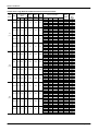
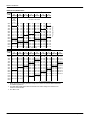
J15 thru 25 ZJ - Standard Drive With Powered Convenience Outlet
Size
(Tons)
Volt
Compressors
(each)
RLA LRA
MCC
OD Fan
Motors
(each)
FLA
Supply
Blower
Motor
FLA
Pwr
Conv
Outlet
FLA
208-3-60 13.1
83
20.5
2.1
15.4
10.0
230-3-60 13.1
83
20.5
2.1
14.4
10.0
460-3-60 6.1
41
9.5
1.1
7.2
5.0
575-3-60 4.4
33
6.8
0.9
5.9
4.0
J15
(15)
TBD
TBD
TBD
TBD
TBD
TBD
TBD
TBD
TBD
TBD
TBD
TBD
TBD
TBD
TBD
TBD
TBD
TBD
TBD
TBD
TBD
TBD
TBD
TBD
TBD
TBD
TBD
TBD
208-3-60 17.9
120
28.0
3.7
15.4
10.0
230-3-60 17.9
120
28.0
3.7
14.4
10.0
460-3-60 9.6
70
15.0
1.9
7.2
5.0
575-3-60 7.4
53
11.5
1.5
5.9
4.0
J18
(17.5)
J20
(20)
18
Electric Heat Option
Model
None
E18
E36
E54
E72
None
E18
E36
E54
E72
None
E18
E36
E54
E72
None
E18
E36
E54
E72
TBD
TBD
TBD
TBD
TBD
TBD
TBD
TBD
TBD
TBD
TBD
TBD
TBD
TBD
TBD
TBD
TBD
TBD
TBD
TBD
None
E18
E36
E54
E72
None
E18
E36
E54
E72
None
E18
E36
E54
E72
None
E18
E36
E54
E72
kW
-13.5
27
40.6
54.1
-18.0
36.0
54.0
72.0
-18.0
36.0
54.0
72.0
-18.0
36.0
54.0
72.0
TBD
TBD
TBD
TBD
TBD
TBD
TBD
TBD
TBD
TBD
TBD
TBD
TBD
TBD
TBD
TBD
TBD
TBD
TBD
TBD
13.5
27.0
40.6
54.1
18.0
36.0
54.0
72.0
18.0
36.0
54.0
72.0
18.0
36.0
54.0
72.0
Stages
-1
2
2
2
-1
2
2
2
-1
2
2
2
-1
2
2
2
TBD
TBD
TBD
TBD
TBD
TBD
TBD
TBD
TBD
TBD
TBD
TBD
TBD
TBD
TBD
TBD
TBD
TBD
TBD
TBD
1
2
2
2
1
2
2
2
1
2
2
2
1
2
2
2
Amps
-37.5
74.9
112.7
150.2
-43.3
86.6
129.9
173.2
-21.7
43.3
65.0
86.6
-17.3
34.6
52.0
69.3
TBD
TBD
TBD
TBD
TBD
TBD
TBD
TBD
TBD
TBD
TBD
TBD
TBD
TBD
TBD
TBD
TBD
TBD
TBD
TBD
37.5
74.9
112.7
150.2
43.3
86.6
129.9
173.2
21.7
43.3
65.0
86.6
17.3
34.6
52.0
69.3
MCA1
(Amps)
90.1
90.1
125.4
172.6
181.9
88.8
88.8
138.8
160.4
203.7
42.8
42.8
69.4
80.2
101.9
32.6
34.0
55.7
64.3
81.7
TBD
TBD
TBD
TBD
TBD
TBD
TBD
TBD
TBD
TBD
TBD
TBD
TBD
TBD
TBD
TBD
TBD
TBD
TBD
TBD
116.3
116.3
125.4
172.6
181.9
115.3
115.3
138.8
160.4
203.7
60.6
60.6
69.4
80.2
101.9
47.4
47.4
55.7
64.3
81.7
Max Fuse2/
Breaker3
Size
(Amps)
100
100
150
175
200
100
100
150
175
225
50
50
70
90
110
35
35
60
70
90
TBD
TBD
TBD
TBD
TBD
TBD
TBD
TBD
TBD
TBD
TBD
TBD
TBD
TBD
TBD
TBD
TBD
TBD
TBD
TBD
125
125
150
175
200
125
125
150
175
225
70
70
70
90
110
50
50
60
70
90
Johnson Controls Unitary Products
860261-JIM-B-0612
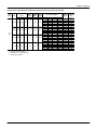
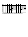
J15 thru 25 ZJ - Standard Drive With Powered Convenience Outlet (Continued)
Size
(Tons)
Volt
Compressors
(each)
RLA LRA
MCC
OD Fan
Motors
(each)
FLA
Supply
Blower
Motor
FLA
Pwr
Conv
Outlet
FLA
208-3-60 22.4
149
35.0
3.7
28.0
10.0
230-3-60 22.4
149
35.0
3.7
26.0
10.0
460-3-60 10.6
75
16.5
1.9
13.0
5.0
575-3-60 7.7
54
12.0
1.5
10.3
4.0
J25
(25)
Electric Heat Option
Model
None
E18
E36
E54
E72
None
E18
E36
E54
E72
None
E18
E36
E54
E72
None
E18
E36
E54
E72
kW
-13.5
27.0
40.6
54.1
-18.0
36.0
54.0
72.0
-18.0
36.0
54.0
72.0
-18.0
36.0
54.0
72.0
Stages
-1
2
2
2
-1
2
2
2
-1
2
2
2
-1
2
2
2
Amps
-37.5
74.9
112.7
150.2
-43.3
86.6
129.9
173.2
-21.7
43.3
65.0
86.6
-17.3
34.6
52.0
69.3
MCA1
(Amps)
149.4
149.4
149.4
188.4
197.7
146.9
146.9
153.3
174.9
218.2
71.3
71.3
76.6
87.5
109.1
53.7
53.7
61.2
69.8
87.2
Max Fuse2/
Breaker3
Size
(Amps)
175
175
175
200
200
150
150
175
175
225
80
80
80
90
110
60
60
70
70
90
1. Minimum Circuit Ampacity.
2. Dual Element, Time Delay Type.
3. HACR type per NEC.
Johnson Controls Unitary Products
19
860261-JIM-B-0612
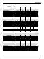
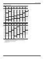
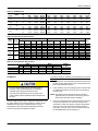
J15 thru 25 ZJ - High Static Drive Without Powered Convenience Outlet
Size
(Tons)
Volt
Compressors
(each)
RLA LRA
MCC
OD Fan
Motors
(each)
FLA
Supply
Blower
Motor
FLA
Pwr
Conv
Outlet
FLA
208-3-60 13.1
83
20.5
2.1
15.4
0.0
230-3-60 13.1
83
20.5
2.1
14.4
0.0
460-3-60 6.1
41
9.5
1.1
7.2
0.0
575-3-60 4.4
33
6.8
0.9
5.9
0.0
J15
(15)
TBD
TBD
TBD
TBD
TBD
TBD
TBD
TBD
TBD
TBD
TBD
TBD
TBD
TBD
TBD
TBD
TBD
TBD
TBD
TBD
TBD
TBD
TBD
TBD
TBD
TBD
TBD
TBD
208-3-60 17.9
120
28.0
3.7
20.0
0.0
230-3-60 17.9
120
28.0
3.7
20.0
0.0
460-3-60 9.6
70
15.0
1.9
10.0
0.0
575-3-60 7.4
53
11.5
1.5
8.2
0.0
J18
(17.5)
J20
(20)
20
MCA1
(Amps)
Electric Heat Option
Model
None
E18
E36
E54
E72
None
E18
E36
E54
E72
None
E18
E36
E54
E72
None
E18
E36
E54
E72
TBD
TBD
TBD
TBD
TBD
TBD
TBD
TBD
TBD
TBD
TBD
TBD
TBD
TBD
TBD
TBD
TBD
TBD
TBD
TBD
None
E18
E36
E54
E72
None
E18
E36
E54
E72
None
E18
E36
E54
E72
None
E18
E36
E54
E72
kW
-13.5
27
40.6
54.1
-18.0
36.0
54.0
72.0
-18.0
36.0
54.0
72.0
-18.0
36.0
54.0
72.0
TBD
TBD
TBD
TBD
TBD
TBD
TBD
TBD
TBD
TBD
TBD
TBD
TBD
TBD
TBD
TBD
TBD
TBD
TBD
TBD
13.5
27.0
40.6
54.1
18.0
36.0
54.0
72.0
18.0
36.0
54.0
72.0
18.0
36.0
54.0
72.0
Stages
-1
2
2
2
-1
2
2
2
-1
2
2
2
-1
2
2
2
TBD
TBD
TBD
TBD
TBD
TBD
TBD
TBD
TBD
TBD
TBD
TBD
TBD
TBD
TBD
TBD
TBD
TBD
TBD
TBD
1
2
2
2
1
2
2
2
1
2
2
2
1
2
2
2
Amps
-37.5
74.9
112.7
150.2
-43.3
86.6
129.9
173.2
-21.7
43.3
65.0
86.6
-17.3
34.6
52.0
69.3
TBD
TBD
TBD
TBD
TBD
TBD
TBD
TBD
TBD
TBD
TBD
TBD
TBD
TBD
TBD
TBD
TBD
TBD
TBD
TBD
37.5
74.9
112.7
150.2
43.3
86.6
129.9
173.2
21.7
43.3
65.0
86.6
17.3
34.6
52.0
69.3
80.1
80.1
112.9
160.1
169.4
78.8
78.8
126.3
147.9
191.2
37.8
37.8
63.1
74.0
95.6
28.6
29.0
50.7
59.3
76.7
TBD
TBD
TBD
TBD
TBD
TBD
TBD
TBD
TBD
TBD
TBD
TBD
TBD
TBD
TBD
TBD
TBD
TBD
TBD
TBD
111.4
111.4
118.7
165.9
175.2
111.4
111.4
133.3
154.9
198.2
58.5
58.5
66.6
77.5
99.1
45.9
45.9
53.6
62.2
79.5
Max Fuse2/
Breaker3
Size
(Amps)
90
90
125
175
200
90
90
150
175
225
45
45
70
90
110
30
30
60
70
90
TBD
TBD
TBD
TBD
TBD
TBD
TBD
TBD
TBD
TBD
TBD
TBD
TBD
TBD
TBD
TBD
TBD
TBD
TBD
TBD
125
125
125
175
200
125
125
150
175
225
60
60
70
90
110
50
50
60
70
90
Johnson Controls Unitary Products
860261-JIM-B-0612
J15 thru 25 ZJ - High Static Drive Without Powered Convenience Outlet (Continued)
Size
(Tons)
Volt
Compressors
(each)
RLA LRA
MCC
OD Fan
Motors
(each)
FLA
Supply
Blower
Motor
FLA
Pwr
Conv
Outlet
FLA
208-3-60 22.4
149
35.0
3.7
38.6
0.0
230-3-60 22.4
149
35.0
3.7
38.6
0.0
460-3-60 10.6
75
16.5
1.9
19.3
0.0
575-3-60 7.7
54
12.0
1.5
15.4
0.0
J25
(25)
MCA1
(Amps)
Electric Heat Option
Model
None
E18
E36
E54
E72
None
E18
E36
E54
E72
None
E18
E36
E54
E72
None
E18
E36
E54
E72
kW
-13.5
27.0
40.6
54.1
-18.0
36.0
54.0
72.0
-18.0
36.0
54.0
72.0
-18.0
36.0
54.0
72.0
Stages
-1
2
2
2
-1
2
2
2
-1
2
2
2
-1
2
2
2
Amps
-37.5
74.9
112.7
150.2
-43.3
86.6
129.9
173.2
-21.7
43.3
65.0
86.6
-17.3
34.6
52.0
69.3
152.7
152.7
152.7
189.1
198.4
152.7
152.7
156.5
178.2
221.5
74.1
74.1
78.3
89.1
110.7
56.1
56.1
62.6
71.2
88.5
Max Fuse2/
Breaker3
Size
(Amps)
175
175
175
200
225
175
175
175
200
250
90
90
90
100
125
70
70
70
80
100
1. Minimum Circuit Ampacity.
2. Dual Element, Time Delay Type.
3. HACR type per NEC.
Johnson Controls Unitary Products
21
860261-JIM-B-0612
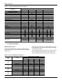
J15 thru 25 ZJ - High Static Drive With Powered Convenience Outlet
Size
(Tons)
Volt
Compressors
(each)
RLA LRA
MCC
OD Fan
Motors
(each)
FLA
Supply
Blower
Motor
FLA
Pwr
Conv
Outlet
FLA
208-3-60 13.1
83
20.5
2.1
15.4
10.0
230-3-60 13.1
83
20.5
2.1
14.4
10.0
460-3-60 6.1
41
9.5
1.1
7.2
5.0
575-3-60 4.4
33
6.8
0.9
5.9
4.0
J15
(15)
TBD
TBD
TBD
TBD
TBD
TBD
TBD
TBD
TBD
TBD
TBD
TBD
TBD
TBD
TBD
TBD
TBD
TBD
TBD
TBD
TBD
TBD
TBD
TBD
TBD
TBD
TBD
TBD
208-3-60 17.9
120
28.0
3.7
20.0
10.0
230-3-60 17.9
120
28.0
3.7
20.0
10.0
460-3-60 9.6
70
15.0
1.9
10.0
5.0
575-3-60 7.4
53
11.5
1.5
8.2
4.0
J18
(17.5)
J20
(20)
22
MCA1
(Amps)
Electric Heat Option
Model
None
E18
E36
E54
E72
None
E18
E36
E54
E72
None
E18
E36
E54
E72
None
E18
E36
E54
E72
TBD
TBD
TBD
TBD
TBD
TBD
TBD
TBD
TBD
TBD
TBD
TBD
TBD
TBD
TBD
TBD
TBD
TBD
TBD
TBD
None
E18
E36
E54
E72
None
E18
E36
E54
E72
None
E18
E36
E54
E72
None
E18
E36
E54
E72
kW
-13.5
27
40.6
54.1
-18.0
36.0
54.0
72.0
-18.0
36.0
54.0
72.0
-18.0
36.0
54.0
72.0
TBD
TBD
TBD
TBD
TBD
TBD
TBD
TBD
TBD
TBD
TBD
TBD
TBD
TBD
TBD
TBD
TBD
TBD
TBD
TBD
13.5
27.0
40.6
54.1
18.0
36.0
54.0
72.0
18.0
36.0
54.0
72.0
18.0
36.0
54.0
72.0
Stages
-1
2
2
2
-1
2
2
2
-1
2
2
2
-1
2
2
2
TBD
TBD
TBD
TBD
TBD
TBD
TBD
TBD
TBD
TBD
TBD
TBD
TBD
TBD
TBD
TBD
TBD
TBD
TBD
TBD
1
2
2
2
1
2
2
2
1
2
2
2
1
2
2
2
Amps
-37.5
74.9
112.7
150.2
-43.3
86.6
129.9
173.2
-21.7
43.3
65.0
86.6
-17.3
34.6
52.0
69.3
TBD
TBD
TBD
TBD
TBD
TBD
TBD
TBD
TBD
TBD
TBD
TBD
TBD
TBD
TBD
TBD
TBD
TBD
TBD
TBD
37.5
74.9
112.7
150.2
43.3
86.6
129.9
173.2
21.7
43.3
65.0
86.6
17.3
34.6
52.0
69.3
90.1
90.1
125.4
172.6
181.9
88.8
88.8
138.8
160.4
203.7
42.8
42.8
69.4
80.2
101.9
32.6
34.0
55.7
64.3
81.7
TBD
TBD
TBD
TBD
TBD
TBD
TBD
TBD
TBD
TBD
TBD
TBD
TBD
TBD
TBD
TBD
TBD
TBD
TBD
TBD
121.4
121.4
131.2
178.4
187.7
121.4
121.4
145.8
167.4
210.7
63.5
63.5
72.9
83.7
105.4
49.9
49.9
58.6
67.2
84.5
Max Fuse2/
Breaker3
Size
(Amps)
100
100
150
175
200
100
100
150
175
225
50
50
70
90
110
35
35
60
70
90
TBD
TBD
TBD
TBD
TBD
TBD
TBD
TBD
TBD
TBD
TBD
TBD
TBD
TBD
TBD
TBD
TBD
TBD
TBD
TBD
125
125
150
200
200
125
125
150
175
225
70
70
80
90
110
50
50
60
70
90
Johnson Controls Unitary Products
860261-JIM-B-0612
J15 thru 25 ZJ - High Static Drive With Powered Convenience Outlet (Continued)
Size
(Tons)
Volt
Compressors
(each)
RLA LRA
MCC
OD Fan
Motors
(each)
FLA
Supply
Blower
Motor
FLA
Pwr
Conv
Outlet
FLA
208-3-60 22.4
149
35.0
3.7
38.6
10.0
230-3-60 22.4
149
35.0
3.7
38.6
10.0
460-3-60 10.6
75
16.5
1.9
19.3
5.0
575-3-60 7.7
54
12.0
1.5
15.4
4.0
J25
(25)
MCA1
(Amps)
Electric Heat Option
Model
None
E18
E36
E54
E72
None
E18
E36
E54
E72
None
E18
E36
E54
E72
None
E18
E36
E54
E72
kW
-13.5
27.0
40.6
54.1
-18.0
36.0
54.0
72.0
-18.0
36.0
54.0
72.0
-18.0
36.0
54.0
72.0
Stages
-1
2
2
2
-1
2
2
2
-1
2
2
2
-1
2
2
2
Amps
-37.5
74.9
112.7
150.2
-43.3
86.6
129.9
173.2
-21.7
43.3
65.0
86.6
-17.3
34.6
52.0
69.3
162.7
162.7
162.7
201.6
210.9
162.7
162.7
169.0
190.7
234.0
79.1
79.1
84.5
95.3
117.0
60.1
60.1
67.6
76.2
93.5
Max Fuse2/
Breaker3
Size
(Amps)
200
200
200
225
225
200
200
200
225
250
90
90
90
110
125
70
70
70
90
100
1. Minimum Circuit Ampacity.
2. Dual Element, Time Delay Type.
3. HACR type per NEC.
Johnson Controls Unitary Products
23
860261-JIM-B-0612
J25ZJ - Low Static Drive Without Powered Convenience Outlet
Size
(Tons)
Volt
Compressors
(each)
RLA LRA
MCC
OD Fan
Motors
(each)
FLA
Supply
Blower
Motor
FLA
Pwr
Conv
Outlet
FLA
208-3-60 22.4
149
35.0
3.7
20.0
0.0
230-3-60 22.4
149
35.0
3.7
20.0
0.0
460-3-60 10.6
75
16.5
1.9
10.0
0.0
575-3-60 7.7
54
12.0
1.5
8.2
0.0
J25
(25)
MCA1
(Amps)
Electric Heat Option
Model
None
E18
E36
E54
E72
None
E18
E36
E54
E72
None
E18
E36
E54
E72
None
E18
E36
E54
E72
kW
-13.5
27.0
40.6
54.1
-18.0
36.0
54.0
72.0
-18.0
36.0
54.0
72.0
-18.0
36.0
54.0
72.0
Stages
-1
2
2
2
-1
2
2
2
-1
2
2
2
-1
2
2
2
Amps
-37.5
74.9
112.7
150.2
-43.3
86.6
129.9
173.2
-21.7
43.3
65.0
86.6
-17.3
34.6
52.0
69.3
130.0
130.0
130.0
165.9
175.2
130.0
130.0
133.3
154.9
198.2
62.7
62.7
66.6
77.5
99.1
47.1
47.1
53.6
62.2
79.5
Max Fuse2/
Breaker3
Size
(Amps)
150
150
150
175
200
150
150
150
175
225
70
70
70
90
110
50
50
60
70
90
1. Minimum Circuit Ampacity.
2. Dual Element, Time Delay Type.
3. HACR type per NEC.
J25ZJ - Low Static Drive With Powered Convenience Outlet
Size
(Tons)
Volt
Compressors
(each)
RLA LRA
MCC
OD Fan
Motors
(each)
FLA
Supply
Blower
Motor
FLA
Pwr
Conv
Outlet
FLA
208-3-60 22.4
149
35.0
3.7
20.0
10.0
230-3-60 22.4
149
35.0
3.7
20.0
10.0
460-3-60 10.6
75
16.5
1.9
10.0
5.0
575-3-60 7.7
54
12.0
1.5
8.2
4.0
J25
(25)
MCA1
(Amps)
Electric Heat Option
Model
None
E18
E36
E54
E72
None
E18
E36
E54
E72
None
E18
E36
E54
E72
None
E18
E36
E54
E72
kW
-13.5
27.0
40.6
54.1
-18.0
36.0
54.0
72.0
-18.0
36.0
54.0
72.0
-18.0
36.0
54.0
72.0
Stages
-1
2
2
2
-1
2
2
2
-1
2
2
2
-1
2
2
2
Amps
-37.5
74.9
112.7
150.2
-43.3
86.6
129.9
173.2
-21.7
43.3
65.0
86.6
-17.3
34.6
52.0
69.3
140.0
140.0
140.0
178.4
187.7
140.0
140.0
145.8
167.4
210.7
67.7
67.7
72.9
83.7
105.4
51.1
51.1
58.6
67.2
84.5
Max Fuse2/
Breaker3
Size
(Amps)
150
150
150
200
200
150
150
150
175
225
70
70
80
90
110
60
60
60
70
90
1. Minimum Circuit Ampacity.
2. Dual Element, Time Delay Type.
3. HACR type per NEC.
24
Johnson Controls Unitary Products
860261-JIM-B-0612
Table 9: J15 thru 25 ZJ Physical Data
Component
Nominal Tonnage
AHRI COOLING PERFORMANCE
Gross Capacity @ AHRI A point (Btu)
AHRI net capacity (Btu)
EER
SEER
IEER
Nominal CFM
System power (KW)
Refrigerant type
Refrigerant charge (lb-oz)
System 1
System 2
System 3
System 4
AHRI HEATING PERFORMANCE
Heating model
Heat input (K Btu)
Heat output (K Btu)
AFUE%
Steady state efficiency (%)
No. burners
No. stages
Temperature Rise Range (ºF)
Gas Limit Setting (ºF)
Gas piping connection (in.)
DIMENSIONS (inches)
Length
Width
Height
OPERATING WT. (lbs.)
COMPRESSORS
Type
Quantity
Unit Capacity Steps (%)
CONDENSER COIL DATA
Face area (Sq. Ft.)
Rows
Fins per inch
Tube diameter (in.)
Circuitry Type
EVAPORATOR COIL DATA
Face area (Sq. Ft.)
Rows
Fins per inch
Tube diameter
Circuitry Type
Refrigerant control
Johnson Controls Unitary Products
Models
J20ZJ
20
J25ZJ
25
TBD
TBD
TBD
TBD
TBD
TBD
TBD
TBD
242000
235000
11.5
13.0
6200
20.10
R-410a
290000
280000
10.5
10.6
7000
26.67
R-410a
TBD
TBD
TBD
TBD
12-0
12-0
12-0
12-0
12-4
12-8
12-8
12-8
J15ZJ
15
J18ZJ
17.5
181400
172000
12.2
12.3
4500
14.10
R-410a
12-0
11-12
12-4
13-8
24
300
240
80
6
2
20-50
195
1
32
400
320
80
8
2
30-60
195
1
TBD
TBD
TBD
TBD
TBD
TBD
TBD
TBD
TBD
TBD
TBD
TBD
TBD
TBD
TBD
TBD
TBD
TBD
TBD
TBD
24
300
240
80
6
2
20-50
195
1
32
400
320
80
8
2
30-60
195
1
180-19/32
92
52-5/8
2697
24
300
240
80
6
2
20-50
195
1
32
400
320
80
8
2
30-60
195
1
2609
TBD
2783
Scroll
4
25 / 50 / 75 / 100
TBD
TBD
TBD
Scroll
4
25 / 50 / 75 / 100
Scroll
4
25 / 50 / 75 / 100
63.8
2
20
3/8
Split-face
TBD
TBD
TBD
TBD
TBD
63.8
2
20
3/8
Split-face
63.8
2
20
3/8
Split-face
25
4
13.5
3/8
Split-face
TXV
TBD
TBD
TBD
TBD
TBD
TBD
25
4
13.5
3/8
Split-face
TXV
25
4
13.5
3/8
Split-face
TXV
25
860261-JIM-B-0612
Table 9: J15 thru 25 ZJ Physical Data (Continued)
Component
Nominal Tonnage
CONDENSER FAN DATA
Quantity
Fan diameter (Inch)
Type
Drive type
No. speeds
Number of motors
Motor HP each
RPM
Nominal total CFM
BELT DRIVE EVAP FAN DATA
Quantity
Fan Size (Inch)
Type
Motor Sheave
Blower Sheave
Belt
Motor HP each
RPM
Frame size
FILTERS
Quantity - Size
Models
J20ZJ
20
J25ZJ
25
TBD
TBD
TBD
TBD
TBD
TBD
TBD
TBD
TBD
4
30
Prop
Direct
1
4
1/3
870
5000
4
30
Prop
Direct
1
4
1/3
870
5000
TBD
TBD
TBD
1
18 X 15
Centrifugal
1VP60
1VP60
BK110
BK090
BX78
BX75
5
7.5
1725
1725
184T
213T
J15ZJ
15
J18ZJ
17.5
4
24
Prop
Direct
1
4
1/3
850
4000
1
15 X 15
Centrifugal
1VP65
1VP65
BK110
BK090
BX85
BX81
5
5
1725
1725
184T
184T
TBD
TBD
TBD
TBD
TBD
TBD
TBD
TBD
TBD
TBD
TBD
TBD
12 - (12 x 24 x 2)1,2
TBD
2 - (20 x 24 x 4),
4 - (24 x 24 x 4)3
TBD
12 - (12 x 24 x 2)1,2
2 - (20 x 24 x 4),
4 - (24 x 24 x 4)3
1VP60
1B5V94
BX78
7.5
1725
213T
1
18 X 15
Centrifugal
1VP75X 1VP75X
1B5V110 1B5V94
5VX840 5VX860
10
15
1725
1725
215T
254T
12 - (12 x 24 x 2)1,2
2 - (20 x 24 x 4),
4 - (24 x 24 x 4)3
1. 2 In. Throwaway, Standard, MERV (Minimum Efficiency Reporting Value) 3.
2. 2 In. Pleated, Optional, MERV 7.
3. 4 In. Pleated, Optional, MERV 13.
Optional Electric Heat
The factory-installed heaters are wired for single point power
supply. Power supply need only be brought into the single point
terminal block.
These CSA approved heaters are located within the central
compartment of the unit with the heater elements extending in
to the supply air chamber.
Fuses are supplied, where required, by the factory. Some kW
sizes require fuses and others do not. refer to Table 10 for
minimum CFM limitations and to Table 8 for electrical data.
Table 10: Electric Heat Minimum Supply Air
Size
(Tons)
J15ZJ
(15)
J18ZJ
(17.5)
J20ZJ
(20)
J25ZJ
(25)
26
Voltage
208/230-3-60
460-3-60
600-3-60
208/230-3-60
460-3-60
600-3-60
208/230-3-60
460-3-60
600-3-60
208/230-3-60
460-3-60
600-3-60
9
4500
4500
4500
6000
6000
6000
6000
6000
6000
7500
7500
7500
Minimum Supply Air (CFM)
Heater kW
18
54
4500
5000
4500
5000
4500
4500
6000
6000
6000
6000
6000
6000
6000
6000
6000
6000
6000
6000
7500
7500
7500
7500
7500
7500
72
5000
4500
4500
6000
6000
6000
6000
6000
6000
7500
7500
7500
Johnson Controls Unitary Products
860261-JIM-B-0612
Optional Gas Heat
These gas-fired heaters have aluminized-steel or optional
stainless steel, tubular heat exchangers with spark ignition with
proven pilot.
Table 11: Gas Application Data
Unit
Size
J15ZJ
J18ZJ
J20ZJ
J25ZJ
Opt.
24
32
24
32
24
32
24
32
Input
(MBH)
300
400
300
400
300
400
300
400
Output (MBH)
240
320
240
320
240
320
240
320
Temp Rise
(°F)1
20-50
30-60
20-50
30-60
20-50
30-60
20-50
30-60
1. On VAV units, individual VAV boxes must be full open in
heating mode to insure airflow falls within temperature rise
range.
Gas Piping
Proper sizing of gas piping depends on the cubic feet per hour
of gas flow required, specific gravity of the gas and the length of
run. “National Fuel Gas Code” Z223.1 (in U.S.A.) or the current
Gas Installation Codes CSA-B149.1 (in Canada) should be
followed in all cases unless superseded by local codes or gas
utility requirements. Refer to the Pipe Sizing Table 12. The
heating value of the gas may differ with locality. The value
should be checked with the local gas utility.
NOTE: There may be a local gas utility requirement specifying
a minimum diameter for gas piping. All units require a
one-inch pipe connection at the entrance fitting.
Main
Manual
Shut-off
Valve
Drip Leg
Figure 14: Bottom Supply Connection External Shut-Off
Table 12: Gas Pipe Sizing - CapacIty of Pipe
Nominal Iron Pipe Size
1 in.
1-1/4 in.
520
1050
350
730
285
590
245
500
215
440
195
400
180
370
170
350
160
320
150
305
Length of
Pipe (ft.)
10
20
30
40
50
60
70
80
90
100
NOTE: Maximum capacity of pipe in cubic feet of gas per hour
based upon a pressure drop of 0.3 inch W.C. and 0.6
specific gravity gas.
Table 13: Gas Heat Minimum Supply Air
Main
Manual
Shut-off
Valve
Size
(Tons)
Heat Size
J15ZJ
(15)
J18ZJ
(17.5)
J20ZJ
(20)
J25ZJ
(25)
24
32
24
32
24
32
24
32
Supply Air (CFM)
Cooling
Heating
Min
Max
Min
Max
4500
7000
4500
7000
4500
7000
4500
7000
6000
8750
6000
8750
6000
8750
6000
8750
6000
9400
6000
9400
6000
9400
6000
9400
7500
12500
7500
12500
7500
12500
7500
12500
Drip Leg
Figure 13: External Supply Connection External Shut-Off
Johnson Controls Unitary Products
27
860261-JIM-B-0612
Gas Connection
The gas supply line can be routed within the space and roof curb,
exiting through the unit’s basepan. Refer to Figure 5 for the gas
piping inlet location. Typical supply piping arrangements are
shown in Figures 13 and 14. All pipe nipples, fittings, and the gas
cock are field supplied.
The furnace and its individual shut-off valve must be
disconnected from the gas supply piping system during
any pressure testing at pressures in excess of 1/2 PSIG.
Pressures greater than 1/2 PSIG will cause gas valve
damage resulting in a hazardous condition. If it is
subjected to a pressure greater than 1/2 PSIG, the gas
valve must be replaced.
Gas piping recommendations:
1.
A drip leg and a ground joint union must be installed in the
gas piping.
2.
Where required by local codes, a manual shut-off valve
must be installed outside of the unit.
3.
Use wrought iron or steel pipe for all gas lines. Pipe dope
should be applied sparingly to male threads only.
Natural gas may contain some propane. Propane is an
excellent solvent and will quickly dissolve white lead and
most standard commercial compounds. A special pipe
dope must be used when assembling wrought iron or
steel pipe. Shellac based compounds such as Gaskolac
or Stalastic, and compounds such as Rectorseal #5,
Clydes’s or John Crane may be used.
4.
All piping should be cleaned of dirt and scale by
hammering on the outside of the pipe and blowing out
loose particles. Before initial start-up, be sure that all gas
lines external to the unit have been purged of air.
5.
The gas supply should be a separate line and installed in
accordance with all safety codes as prescribed under
“Limitations”.
6.
A 1/8-inch NPT plugged tapping, accessible for test gage
connection, must be installed immediately upstream of the
gas supply connection to the unit.
7.
After the gas connections have been completed, open the
main shut-off valve admitting normal gas pressure to the
mains. Check all joints for leaks with soap solution or other
material suitable for the purpose. NEVER USE A FLAME.
FIRE OR EXPLOSION HAZARD
The furnace must be isolated from the gas supply piping
system by closing its individual manual shut-off valve
during any pressure testing of the gas supply piping
system at test pressures equal to or less than 1/2 PSIG.
Threaded joints should be coated with a sealing
compound that is resistant to the action of liquefied
petroleum gases. Do not use Teflon tape.
Lp Units, Tanks And Piping
All gas heat units are shipped from the factory equipped for
natural gas use only. The unit may be converted in the field for
use with LP gas with accessory kit model number 1NP0418.
All LP gas equipment must conform to the safety standards of
the National Fire Protection Association.
For satisfactory operation, LP gas pressure must be 10.0 inch
W.C. at the unit under full load. Maintaining proper gas
pressure depends on three main factors:
1.
The vaporization rate which depends on the temperature of
the liquid and the “wetted surface” area of the container(s).
2.
The proper pressure regulation. (Two-stage regulation is
recommended).
3.
The pressure drop in the lines between regulators and
between the second stage regulator and the appliance.
Pipe size required will depend on the length of the pipe run
and the total load of all appliances.
Complete information regarding tank sizing for vaporization,
recommended regulator settings, and pipe sizing is available
from most regulator manufacturers and LP gas suppliers.
Failure to follow the safety warning exactly could result
in serious injury, death or property damage.
Never test for gas leaks with an open flame. use a
commercially available soap solution made specifically
for the detection of leaks to check all connections. A fire
or explosion may result causing property damage,
personal injury or loss of life.
28
LP gas is an excellent solvent and will quickly dissolve
white lead and most standard commercial compounds. A
special pipe dope must be used when assembling
wrought iron or steel pipe for LP. Shellac base
compounds such as Gaskolac or Stalastic, and
compounds such as Rectorseal #5, Clyde’s, or John
Crane may be used.
Johnson Controls Unitary Products
860261-JIM-B-0612
Check all connections for leaks when piping is completed using
a soap solution. NEVER USE A FLAME.
Options/Accessories
Electric Heat
FIRE OR EXPLOSION HAZARD
Failure to follow the safety warning exactly could result
in serious injury, death or property damage.
Never test for gas leaks with an open flame. use a
commercially available soap solution made specifically
for the detection of leaks to check all connections. A fire
or explosion may result causing property damage,
personal injury or loss of life.
Vent And Combustion Air
Two vent hoods and a combustion air hood (with screens) are
shipped attached to the blower housing in the blower
compartment. For units with factory installed VFD option, the
hoods and accompanying hardware are shipped inside the
gas heat section. These hoods must be installed to assure
proper unit function. All hoods must be fastened to the
outside of the gas heat access panel with the screws
provided in the bag also attached to the blower housing.
The screen for the combustion air intake hood is secured to
the inside of the access panel opening with four fasteners and
the screws used for mounting the hood to the panel. The top
flange of this hood slips in under the top of the access panel
opening when installing. Refer to Vent and Combustion Air
Hood Figure 15.
Electric heaters are available as a factory-installed option.
These heaters mount in the heat compartment with the
heating elements extending into the supply air chamber. All
electric heaters are fused and intended for use with single
point power supply.
Economizer/Motorized Outdoor Damper Rain Hood
The instruction for the optional economizer/motorized damper
rain hood can be found in the rain hood kit. Use these
instructions when field assembling an economizer rain hood
onto a unit. The outdoor and return air dampers, the damper
actuator, the damper linkage, the outdoor and return air divider
baffles, and all the control sensors are factory mounted as part
of the “Factory installed” economizer option.
Power Exhaust/Barometric Relief Damper and Rain Hood
The instructions for the power exhaust/barometric relief damper
and rain hood can be found in the rain hood kit. The exhaust
fan, all supporting brackets, angles, and the wiring are factory
installed as part of the power exhaust option.
Economizer And Power Exhaust Set Point
Adjustments
Remove the top rear access panel from the unit. Locate the
economizer control module, where the following adjustments
will be made.
Each vent hood is installed by inserting the top flange of the
hood into the slotted opening in the access panel and securing
in place.
The products of combustion are discharged horizontally
through these two screened, hooded vent openings on the
upper gas heat access panel.
Extreme care must be exercised in turning all set point,
maximum and minimum damper positioning adjustment
screws to prevent twisting them off.
Minimum Position Adjustment
Slotted Openings in
Access Panel
Vent Air
Outlet Hoods
• Check that the damper blades move smoothly without
binding; carefully turn the Minimum Position Adjust screw
(found on the damper control module) fully clockwise and
then set the thermostat indoor fan switch to the ON
position and then OFF or energize and de-energize
terminals “R” to “G”.
• With the thermostat set to the indoor fan ON position or
terminals “R” to “G” energized, turn the Minimum Position
Adjusting screw (located on the damper control module)
counterclockwise until the desired minimum damper
position has been attained.
Combustion Air
Intake Hood
Gas Heat
Access Panels
Enthalpy Set Point Adjustment
• The enthalpy set point may now be set by selecting the
desired set point shown in the Enthalpy Set Point
Adjustment Figure 16. Adjust as follows:
Figure 15: Vent and Combustion Air Hood
Johnson Controls Unitary Products
• For a single enthalpy operation carefully turn the set
point adjusting screw (found on the damper control
29
860261-JIM-B-0612
module) to the “A”, “B”, “C” or “D” setting corresponding
to the lettered curve of the Enthalpy Set Point
Adjustment Figure 17.
• For a dual enthalpy operation, carefully turn the set point
adjusting screw fully clockwise past the "D" setting.
Power Exhaust Damper Set Point
With power exhaust option, each building pressurization
requirement will be different. The point at which the power
exhaust comes on is determined by the economizer damper
position (Percent Open). The Exhaust Air Adjustment Screw
should be set at the Percent Open of the economizer damper at
which the power exhaust is needed. It can be set from 0 to
100% damper open.
Indoor Air Quality AQ
Indoor Air Quality (indoor sensor input): Terminal AQ accepts a
+2 to +10 Vdc signal with respect to the (AQ1) terminal. When
the signal is below it's set point, the actuator is allowed to
modulate normally in accordance with the enthalpy and mixed
air sensor inputs. When the AQ signal exceeds it's set point
setting and there is no call for free cooling, the actuator is
proportionately modulated from the 2 to 10 Vdc signal, with 2
Vdc corresponding to full closed and 10 Vdc corresponding to
full open. When there is no call for free cooling, the damper
position is limited by the IAQ Max damper position setting.
When the signal exceeds it's set point (Demand Control
Ventilation Set Point) setting and there is a call for free cooling,
the actuator modulates from the minimum position to the full
open position based on the highest call from either the mixed
air sensor input or the AQ voltage input.
• Optional CO2 Space Sensor Kit Part # 2AQ04700324
• Optional CO2 Sensor Kit Part # 2AQ04700424
Replace the top rear access panel on the unit.
Optional BAS-Ready Economizer Power Exhaust
Damper Set Point Adjustment
Remove the economizer access panel from the unit. Loosen,
but do not remove the two panel latches. Locate the
economizer actuator, where the following adjustment can be
made.
With power exhaust option, each building pressurization
requirement will be different. The point at which the power
exhaust comes on is determined by the economizer's outdoor
damper position. The actuator's auxiliary switch adjustment
screw should be set at the damper position at which the power
exhaust is needed. The adjustment screw can be set between
25 to 85 degrees open.
Replace the economizer access panel.
Optional Variable Air Volume (VAV)
A variable air volume (VAV) option using a variable frequency
drive (VFD) is available for applications requiring a constant
supply duct static pressure. A differential pressure transducer is
used to monitor supply duct static pressure and return a speed
30
reference signal to the VFD to control the output of the indoor
blower motor.
Duct Static Pressure Transducer
A 0-5" WC pressure transducer, located in the control box
compartment, is used to sense static (gauge) pressure in the
supply air duct and convert this pressure measurement to a
proportional 0-5 VDC electrical output.
Pressure-transmitting plastic tubing (1/4" diameter) must be
field supplied and installed from the transducer to both the
ductwork and to the atmosphere. Connect the tubing from the
'HIGH' pressure tap of the transducer to a static pressure tap
(field supplied) in the supply duct located at a point where
constant pressure is expected. To prevent an unstable signal
due to air turbulence, there should be no obstructions, turns or
VAV terminal boxes up- or down-stream of the sensing tube
location for at least a distance of 6-10 times the duct diameter.
Tubing must also be run between the 'LOW' pressure tap of the
transducer and atmospheric pressure (outside of the unit).
Do not run plastic tubing in the supply or return air ducts
as air movement could cause erroneous pressure
measurements. If the tubing penetrates through the
bottom of the unit be sure openings are sealed to
prevent air and water leakage.
Vav Control Board
A VAV control board, located in the top-left corner of the control
box, is used to convert the pressure transducer input signal into
a speed reference signal that the drive uses to control the
speed of the blower motor. This modulating speed reference
signal is generated using an internal algorithm which
continuously calculates an output value.
A brief description of the VAV board's I/O terminals that are
used follows:
Inputs:
• DUCT PRES - a 0-5 VDC analog input provided by a
factory-installed duct static pressure transducer located in
the unit's control box.
• SAT - analog input provided by a factory-installed
10k-ohm, type 3 thermistor located in the unit's supply
air compartment.
• RAT - analog input provided by a factory-installed 10k-ohm,
type 3 thermistor located in the unit's return air compartment.
• OAT - analog input provided by a factory-installed 10k-ohm,
type 3 thermistor located in the outdoor air compartment or
mounted within the evaporator base rail for units without the
installed economizer option.
• ST - analog input provided by field-installed space
temperature sensor.
Johnson Controls Unitary Products
860261-JIM-B-0612
• OH - a 0-10 VDC analog input provided by a field-installed
outdoor air relative humidity sensor for single enthalpy
economizer configuration.
• RH - a 0-10 VDC analog input provided by a field-installed
return air relative humidity sensor for dual enthalpy
economizer configuration (used with OH).
NOTE: Either of the set points described above can be
changed through the unit control board (UCB) with the
use of a USB-to-RS485 converter, personal computer
or PDA and a down-loaded copy of the Simplicity®
software available at the UPGnet Commercial Product
Catalog website.
• IAQ - a 0-10 VDC analog input provided by a field-installed
carbon dioxide sensor which monitors indoor air quality
(CO2 concentration) and enables call for Demand
Ventilation mode for units installed with economizer option.
• OAQ - a 0-10 VDC analog input provided by a fieldinstalled carbon dioxide sensor which monitors outdoor air
quality (CO2 concentration) and, along with IAQ, enables
call for Differential Demand Ventilation mode for units
installed with economizer option.
• APS - a 24 VAC binary input provided by a field-installed
air proving switch which monitors the pressure difference
across the indoor blower.
• PUR - a 24 VAC binary input for building purge calls from
an external source.
• OCC - a 24 VAC binary input used to set the building
occupancy status for the control.
• LIMIT 2 - a 24 VAC binary input which either confirms
2nd-stage gas heat operation or receives an error signal
from the variable frequency drive.
Outputs:
• FAN - a 2-10 VDC analog output signal sent to the VFD to
modulate the speed of the indoor blower motor.
• ECON - a 2-10 VDC analog output signal sent to the
economizer actuator to modulate position of the return air
and outdoor air dampers (optional).
• EXH ~ - a 24 VAC binary output signal used to turn on/off
the power exhaust relay (optional).
• VAV BOX (gas/electric heat only) - a normally open
relay contact connected to a terminal block, used to drive
the building's VAV boxes to full-open during heating
operation.
Programmable set points:
The duct static set point is the pressure that the drive will
maintain when operating the unit in VAV mode. The set-point is
adjustable between 0" WC and 5" WC with the default setting of
1.5" WC.
The duct static high-limit set point is the maximum allowable
duct pressure to prevent damage from over-pressurization of
the ductwork in the event of either a drive or damper failure.
The high-limit set-point is adjustable between 0" WC and 5" WC
with the factory default setting of 4.5" WC. If the duct static
pressure reaches the high-limit set point, then the supply fan
motor will be shutdown.
Johnson Controls Unitary Products
The customer must be aware of the duct pressure
design limit, and what the duct pressure sensor is
reading when the peak pressure is reached (i.e. the
pressure transducer sensing tube may not be located at
the place of highest pressure in the system).
Factory-installed VFD
The factory-installed VFD is mounted in the Blower Access
Compartment above the blower assembly. The drive comes
wired from the factory to include both 3-phase power and
control connections (run permit signal, speed reference signal &
fault signal).
All required drive parameters are pre-programmed at the factory,
except in the case of 208-volt applications, in which the
parameter that defines motor nameplate voltage must be
changed to a value of 208.00 and the parameter that defines
motor-rated current must be changed to the appropriate value
appearing on the motor's nameplate. Refer to the enclosed drive
material or access the UPGnet Commercial Product Catalog
website for instructions on changing parameter settings.
For units also equipped with gas/electric heat, a terminal block
located in the unit's control box and connected to the VAV
board's "VAV BOX" terminal, must be field wired to the
building's VAV boxes to ensure fully open dampers during
heating operation.
Manual Bypass
An optional, factory-installed manual bypass switch available
with factory-installed VFD can be found in the Blower Motor
Access compartment and has the following three positions:
• DRIVE - routes power through the VFD for modulating
control of the indoor blower motor.
• LINE (or BYPASS) - routes power directly to the motor
which provides full-speed motor operation and complete
electrical isolation of the drive.
• TEST - routes power to the VFD but not to the motor to
allow for drive programming and/or diagnostics.
If a drive failure occurs, the unit does not automatically switch to
bypass mode. The LINE/DRIVE/TEST switch must be manually
switched to the LINE (BYPASS) position. If there is a call for the
fan, the indoor blower motor will run at full-speed while in the
bypass mode.
31
860261-JIM-B-0612
'VFD-Ready' For Customer-installation
If the unit is operated with the manual bypass switch in
the LINE (BYPASS) position and there are VAV boxes
present in the duct system, then boxes must be driven to
the full-open position using a customer-supplied power
source to prevent over-pressurizing and possible
damage to the ductwork.
Before beginning any service, disconnect all power to
the drive. Be aware that high voltages are present in the
drive even after power has been disconnected.
Capacitors within the drive must be allowed to discharge
before beginning service.
BAS-Ready VFD
Factory-installed VFD is also available with 'BAS-ready'
models. Terminal blocks are provided in the control box (in
place of the VAV control board) for field wiring of a customerinstalled BAS to receive 24 VAC power and to connect to the
following control signals:
Units configured as 'VFD-ready' provide provisions for a
customer-installed drive. The physical dimensions of VFDs can
vary greatly among manufacturers, horsepower ratings and
voltage requirements. Keep in mind that drive manufacturers
also require various minimum clearances to allow for adequate
internal cooling of the drive during operation.
The unit comes with a mounting bracket installed in the Blower
Access compartment which may accommodate other vendor's
drives depending on their size. In order to utilize the unit's
mounting bracket, the maximum recommended drive
dimensions are as follows:
For 5-hp motor applications ....................... 13" H x 6" W x 7" D
For 7.5 thru 15-hp motor applications ........ 13" H x 8" W x 8" D
If the drive will not fit in the allotted space, then it will need to be
mounted elsewhere; either within the building on a perpendicular
wall which is not subjected to excessive temperature, vibration,
humidity, dust, corrosive gas, explosive gas, etc., or within an
appropriate enclosure rated for outside installation to safeguard
against moisture, dust and excessive heat.
The power leads to the drive (L1, L2, L3) and from the motor
(T1, T2, T3) along with the respective ground wires are supplied
with the unit and need to be connected after the drive is
installed.
• a duct static pressure transducer input signal (0-5 VDC)
• an economizer actuator input signal (2-10 VDC)
• an economizer actuator output signal (2-10 VDC)
• a VFD speed reference output signal (2-10 VDC)
The use of shielded cable is recommended for the above
control wiring connections.
NOTE: Factory-installed VFD is not available with factoryinstalled BAS options due to space limitations in the
control box.
A solid-state, lock-out relay (LR) and 100-F, 50 VDC capacitor
must be field-supplied and installed to provide a means to
transmit a potential fault signal back to the BAS controller. The
specific relay part number required will depend upon the need
for either AC-output or DC-output. See price pages for further
details.
Once the appropriate relay and capacitor are obtained, install
the capacitor across LR terminals '3' & '4' and make the
following wiring connections:
• LR '1' to BAS controller
• LR '2' to BAS controller
• LR '3' to UCB 'X'
• LR '4' to UCB 'C'
32
Do not connect AC power to the T1, T2, T3 drive
terminals to prevent damage to the VFD.
A terminal block located in the control box is provided for field
connection of the VFD speed reference signal (2-10 VDC) and
to the normally-open, run-permit auxiliary contact. The use of
shielded cable is recommended for the above control wiring
connections.
For VFD-ready units also equipped with gas/electric heat, a
terminal block located in the unit's control box and connected to
the VAV board's "VAV BOX" terminal, must be field wired to the
building's VAV boxes to ensure fully open dampers during
heating operation.
Optional Hot Gas Bypass (HGBP)
To allow for low cooling load operation, a direct-acting,
pressure-modulating bypass control valve installed on the
system #1 discharge line is used to divert high temperature,
high pressure refrigerant around the TXV in order to maintain a
desired minimum evaporator pressure.
The opening pressure of the bypass valve is fully adjustable
between 0 and 80 psig with a factory-setting of 60 psig. HGBP
is standard on all units with VAV and optional with CV units.
Johnson Controls Unitary Products
860261-JIM-B-0612
CONTROL
CURVE
CONTROL POINT
APPROX. 0F (0C)
AT 50% RH
A
73 (23)
B
C
70 (21)
67 (19)
D
63 (17)
85 90 95 100 105 110
(29) (32) (35) (38) (41) (43)
80
(27)
75
(24)
70
(21)
65
(18)
60
(16)
55
(13)
50
(10)
45
(7)
35
(2)
A
B
C
D
40
(4)
B A
D C
35
(2)
40 45 50 55 60 65 70 75 80 85 90 95 100 105 110
(4) (7) (10) (13) (16) (18) (21) (24) (27) (29) (32) (35) (38) (41) (43)
APPROXIMATE DRY BULB TEMPERATURE - 0F (0C)
Figure 16: Enthalpy Set Point Chart
Exhaust Air
Adjustment
Screw
Exhaust Air LED
Damper Min.
Position
Screw
Indoor Air Quality
Max. Adjustment
Screw
N1
N
EXH
Set
TR
P1
P
EXH
24
Vac
HOT
T1
T
Min
Pos
IAQ
Max
Indoor Air Quality
LED
AQ1
AQ
IAQ
SO
IAQ
Min
TR1
24
Vac
COM
+
1
2
5
Indoor Air Quality
Min. Adjustment
Screw
Free Cooling LED
SO+
3
4
EF
EF1
Free
Cool
SR+
SR
B
A
C
D
Economizer Enthalpy
Set Point Adjustment
Screw
Figure 17: Economizer Control (Excludes VFD and BAS Options)
Johnson Controls Unitary Products
33
860261-JIM-B-0612
Phasing
Johnson Controls Model J**ZJ units are properly phased at the
factory. Check for proper compressor rotation. If the blower or
compressors rotate in the wrong direction at start-up, the
electrical connection to the unit is misphased. Change the
phasing of the Field Line Connection at the factory or field
supplied disconnect to obtain proper rotation. (Scroll
compressors operate in only one direction. If the scroll is
drawing low amperage, has similar suction and discharge
pressures, or producing a high noise level, the scroll is
misphased.)
Scroll compressors require proper rotation to operate
correctly. Units are properly phased at the factory. Do
not change the internal wiring to make the blower
condenser fans, or compressor rotate correctly.
Blower Rotation
Procedure for adjusting belt tension:
1. Loosen six nuts (top and bottom) A.
2. Adjust by turning (B).
3. Never loosen nuts (C).
4. Use belt tension checker to apply a perpendicular
force to one belt at the midpoint of the span as
shown. Deflection distance of 4mm (5/32”) is
obtained.
To determine the deflection distance from normal
position, use a straight edge from sheave to sheave as
reference line. The recommended deflection force is as
follows:
Tension new belts at the max. deflection force
recommended for the belt section. Check the belt
tension at least two times during the first 24 hours of
operation. Any retensioning should fall between the min.
and max. deflection force values.
5. After adjusting retighten nuts (A).
Check for proper supply air blower rotation. If the blower is
rotating backwards, the line voltage at the unit point of power
connection is misphased (See ‘PHASING’).
CFM Static Pressure and Power-Altitude and Temperature
Corrections
Belt Tension
The information below should be used to assist in application of
product when being applied at altitudes at or exceeding 1000
feet above sea level.
The tension on the belt should be adjusted as shown in Figure 18.
The air flow rates listed in the standard blower performance
tables are based on standard air at sea level. As the altitude or
temperature increases, the density of air decreases. In order to
use the indoor blower tables for high altitude applications,
certain corrections are necessary.
Span Length
Defl Force
(B)
A centrifugal fan is a “constant volume” device. This means
that, if the rpm remains constant, the CFM delivered is the
same regardless of the density of the air. However, since the air
at high altitude is less dense, less static pressure will be
generated and less power will be required than a similar
application at sea level. Air density correction factors are shown
in Table 14 and Figure 19.
*Never Loosen
(A)
(C)*
Figure 18: Belt Adjustment
34
Johnson Controls Unitary Products
860261-JIM-B-0612
Table 14: Altitude/Temperature Correction Factors
Air
Temp.
40
50
60
70
80
90
100
0
1.060
1.039
1.019
1.000
0.982
0.964
0.946
1000
1.022
1.002
0.982
0.964
0.947
0.929
0.912
2000
0.986
0.966
0.948
0.930
0.913
0.897
0.880
3000
0.950
0.931
0.913
0.896
0.880
0.864
0.848
4000
0.916
0.898
0.880
0.864
0.848
0.833
0.817
Altitude (Ft.)
5000
0.882
0.864
0.848
0.832
0.817
0.802
0.787
6000
0.849
0.832
0.816
0.801
0.787
0.772
0.758
7000
0.818
0.802
0.787
0.772
0.758
0.744
0.730
8000
0.788
0.772
0.757
0.743
0.730
0.716
0.703
9000
0.758
0.743
0.729
0.715
0.702
0.689
0.676
10000
0.729
0.715
0.701
0.688
0.676
0.663
0.651
1.100
1.050
Correction Factor
1.000
Sea Level
0.950
1000 ft
0.900
2000 ft
3000 ft
0.850
4000 ft
0.800
5000 ft
0.750
6000 ft
7000 ft
8000 ft
0.700
9000 ft
10000 ft
0.650
0.600
40
50
60
70
80
90
100
Air Temperature (ºF)
Figure 19: Altitude/Temperature Correction Factors
The examples below will assist in determining the airflow
performance of the product at altitude.
blower tables to select the blower speed and the BHP
requirement.
Example 1: What are the corrected CFM, static pressure, and
BHP at an elevation of 5,000 ft. if the blower performance data
is 6,000 CFM, 1.5 IWC and 4.0 BHP?
Solution: As in the example above, no temperature
information is given so 70°F is assumed.
Solution: At an elevation of 5,000 ft. the indoor blower will still
deliver 6,000 CFM if the rpm is unchanged. However, Table 14
must be used to determine the static pressure and BHP. Since
no temperature data is given, we will assume an air temperature
of 70°F. Table 14 shows the correction factor to be 0.832.
Corrected static pressure = 1.5 x 0.832 = 1.248 IWC
Corrected BHP = 4.0 x 0.832 = 3.328
Example 2: A system, located at 5,000 feet of elevation, is to
deliver 6,000 CFM at a static pressure of 1.5". Use the unit
Johnson Controls Unitary Products
The 1.5" static pressure given is at an elevation of 5,000 ft. The
first step is to convert this static pressure to equivalent sea level
conditions.
Sea level static pressure = 1.5 / .832 = 1.80"
Enter the blower table at 6000 sCFM and static pressure of
1.8". The rpm listed will be the same rpm needed at 5,000 ft.
Suppose that the corresponding BHP listed in the table is 3.2.
This value must be corrected for elevation.
BHP at 5,000 ft. = 3.2 x .832 = 2.66
35
860261-JIM-B-0612
Drive Selection
1.
Determine side or bottom supply duct application.
2.
Determine desired airflow
3.
Calculate or measure the amount of external static pressure.
4.
Using the operating point determined from steps 1, 2 & 3, locate this point on the appropriate supply air blower performance
table. (Linear interpolation may be necessary.)
5.
Noting the RPM and BHP from step 4, locate the appropriate motor and/or drive on the RPM selection table.
6.
Review the BHP compared to the motor options available. Select the appropriate motor and/or drive.
7.
Review the RPM range for the motor options available. Select the appropriate drive if multiple drives are available for the
chosen motor.
8.
Determine turns open to obtain the desired operation point.
Example
1.
6800 CFM
2.
2.0 iwg
3.
Using the supply air blower performance table below, the following data point was located: 1020 RPM & 5.92 BHP.
4.
Using the RPM selection table below, Size X and Model Y is found.
5.
5.92 BHP exceeds the maximum continuous BHP rating of the 5.0 HP motor. The 7.5 HP motor is required.
6.
1020 RPM is within the range of the 7.5 HP drives.
7.
Using the 7.5 HP motor and drive, 3.5 turns open will achieve 1020 RPM.
Example Supply Air Blower Performance
Air Flow
(CFM)
6400
6800
7200
7600
Available External Static Pressure - IWG
0.4
0.6
0.8
1.0
1.2
1.4
1.6
1.8
2.0
2.2
2.4
2.6
RPM BHP RPM BHP RPM BHP RPM BHP RPM BHP RPM BHP RPM BHP RPM BHP RPM BHP RPM BHP RPM BHP RPM BHP
Standard
5 HP & Field
Supplied
Drive
719 2.55
742 3.02
765 3.54
790 4.11
Standard 5 HP & Drive
756
778
802
827
3.03
3.51
4.03
4.60
792
814
838
863
3.49
3.97
4.49
5.06
828
850
874
899
3.92
4.40
4.92
5.49
864
886
910
935
High Static 7.5 HP & Drive
4.32
4.79
5.32
5.88
899
921
945
970
4.67 933
5.15 955
5.67 979
6.24 1004
4.98 966 5.24 998 5.45 1028
5.46 988 5.72 1020 5.92 1050
5.98 1012 6.24 1044 6.44 1074
6.55 1037 6.81 1069 7.01 1099
5.59
6.07
6.59
7.16
1056 5.67 1083 5.68
1078 6.15 1105 6.16
1102 6.67 1129 6.68
1127 7.24 1154 7.25
7.5 HP & Field
Supplied Drive
Table X: RPM Selection
Size
(Tons)
Model
HP
X
Y
5
7.5
36
Max
BHP
5.75
8.63
Motor
Sheave
1VP60
1VP60
Blower
Sheave
BK110
BK090
6 Turns
Open
730
905
5 Turns
Open
765
950
4 Turns
Open
800
990
3 Turns
Open
835
1035
2 Turns
Open
870
1075
1 Turn
Open
905
1120
Fully
Closed
N/A
N/A
Johnson Controls Unitary Products
860261-JIM-B-0612
Table 15: Air Flow Performance - Side Duct Application
J15ZJ (15 Ton) Side Duct
Air Flow
(CFM)
4000
4400
4800
5200
5600
6000
6400
6800
7200
Available External Static Pressure - IWG1
0.4
0.6
0.8
1.0
1.2
1.4
1.6
1.8
2.0
2.2
2.4
2.6
RPM BHP RPM BHP RPM BHP RPM BHP RPM BHP RPM BHP RPM BHP RPM BHP RPM BHP RPM BHP RPM BHP RPM BHP
Standard 5 HP & Field Supplied Drive
727 1.14 765 1.47 806 1.77
753 1.51 792 1.84 832 2.14
781 1.92 820 2.25 861 2.55
812 2.37 850 2.70 891 3.00
844 2.86 882 3.19 923 3.49
877 3.39 916 3.72 957 4.02
912 3.96 951 4.29 992 4.59
949 4.56 988 4.89 1028 5.19
986 5.20 1025 5.53
-
848
874
903
933
965
999
1034
1070
-
2.04
2.41
2.82
3.27
3.76
4.29
4.86
5.46
-
Standard 5 HP & Drive
891 2.29 934 2.52
917 2.66 960 2.88
946 3.06 989 3.29
976 3.52 1019 3.74
1008 4.01 1051 4.23
1042 4.54 1085 4.76
1077 5.10 1120 5.33
1113 5.71
-
977
1004
1032
1062
1094
1128
1163
-
2.73
3.09
3.50
3.95
4.45
4.98
5.54
-
1020
1046
1074
1105
1137
1170
1205
-
2.93
3.29
3.70
4.15
4.64
5.17
5.74
-
1061
1087
1116
1146
1178
1212
-
High Static 5 HP & Drive
3.12 1101 3.30 1138 3.48 1174 3.67
3.48 1127 3.67 1165 3.85 1200 4.03
3.89 1155 4.08 1193 4.26 1228 4.44
4.34 1186 4.53 1223 4.71 1259 4.89
4.83 1218 5.02 1255 5.20 1291 5.39
5.36 1251 5.55 1289 5.73
5 HP & Field Supplied Drive
1. Blower performance includes gas heat exchangers and 2” filters. See STATIC RESISTANCE table for additional applications.
2. See RPM SELECTION table to determine desired motor sheave setting and to determine the maximum continuous BHP.
3. kW = BHP x 0.898.
J18ZJ (17.5 Ton) Side Duct
Air Flow
(CFM)
4400
4800
5200
5600
6000
6400
6800
7200
7600
8000
8400
8800
Available External Static Pressure - IWG1
0.4
0.6
0.8
1.0
1.2
1.4
1.6
1.8
2.0
2.2
2.4
2.6
RPM BHP RPM BHP RPM BHP RPM BHP RPM BHP RPM BHP RPM BHP RPM BHP RPM BHP RPM BHP RPM BHP RPM BHP
Standard 5 HP & Field Supplied Drive
TBD TBD TBD TBD TBD TBD
TBD TBD TBD TBD TBD TBD
TBD TBD TBD TBD TBD TBD
TBD TBD TBD TBD TBD TBD
TBD TBD TBD TBD TBD TBD
TBD TBD TBD TBD TBD TBD
TBD TBD TBD TBD TBD TBD
TBD TBD TBD TBD TBD TBD
TBD TBD TBD TBD TBD TBD
TBD TBD TBD TBD TBD TBD
TBD TBD TBD TBD TBD TBD
TBD TBD TBD TBD TBD TBD
TBD
TBD
TBD
TBD
TBD
TBD
TBD
TBD
TBD
TBD
TBD
TBD
TBD
TBD
TBD
TBD
TBD
TBD
TBD
TBD
TBD
TBD
TBD
TBD
TBD
TBD
TBD
TBD
TBD
TBD
TBD
TBD
TBD
TBD
TBD
TBD
Standard 5 HP & Drive
TBD TBD TBD TBD
TBD TBD TBD TBD
TBD TBD TBD TBD
TBD TBD TBD TBD
TBD TBD TBD TBD
TBD TBD TBD TBD
TBD TBD TBD TBD
TBD TBD TBD TBD
TBD TBD TBD TBD
TBD TBD TBD TBD
TBD TBD TBD TBD
TBD TBD TBD TBD
TBD
TBD
TBD
TBD
TBD
TBD
TBD
TBD
TBD
TBD
TBD
TBD
TBD
TBD
TBD
TBD
TBD
TBD
TBD
TBD
TBD
TBD
TBD
TBD
TBD
TBD
TBD
TBD
TBD
TBD
TBD
TBD
TBD
TBD
TBD
TBD
TBD
TBD
TBD
TBD
TBD
TBD
TBD
TBD
TBD
TBD
TBD
TBD
TBD
TBD
TBD
TBD
TBD
TBD
TBD
TBD
TBD
TBD
TBD
TBD
High Static 7.5 HP & Drive
TBD TBD TBD TBD TBD TBD
TBD TBD TBD TBD TBD TBD
TBD TBD TBD TBD TBD TBD
TBD TBD TBD TBD TBD TBD
TBD TBD TBD TBD TBD TBD
TBD TBD TBD TBD TBD TBD
TBD TBD TBD TBD TBD TBD
TBD TBD TBD TBD TBD TBD
TBD TBD TBD TBD TBD TBD
TBD TBD TBD TBD TBD TBD
TBD TBD TBD TBD TBD TBD
TBD TBD TBD TBD TBD TBD
7.5 HP & Field Supplied Drive
1. Blower performance includes gas heat exchangers and 2” filters. See STATIC RESISTANCE table for additional applications.
2. See RPM SELECTION table to determine desired motor sheave setting and to determine the maximum continuous BHP.
3. kW = BHP x 0.838.
Johnson Controls Unitary Products
37
860261-JIM-B-0612
J20ZJ (20 Ton) Side Duct
Air Flow
(CFM)
5200
5600
6000
6400
6800
7200
7600
8000
8400
8800
9200
9600
10000
Available External Static Pressure - IWG1
0.4
0.6
0.8
1.0
1.2
1.4
1.6
1.8
2.0
2.2
2.4
2.6
RPM BHP RPM BHP RPM BHP RPM BHP RPM BHP RPM BHP RPM BHP RPM BHP RPM BHP RPM BHP RPM BHP RPM BHP
Standard 5 HP & Field
Supplied Drive
663 1.34 700 1.83 736
680 1.71 717 2.20 753
699 2.11 735 2.60 772
719 2.55 756 3.03 792
742 3.02 778 3.51 814
765 3.54 802 4.03 838
790 4.11 827 4.60 863
817 4.72 853 5.21 890
845 5.38 881 5.87 918
874 6.09 911 6.58 947
905 6.85 941 7.33 977
936 7.65 973 8.13 1009
969 8.49
-
Standard 5 HP & Drive
2.29 772
2.66 789
3.06 808
3.49 828
3.97 850
4.49 874
5.06 899
5.67 926
6.33 954
7.04 983
7.79 1014
8.59
-
2.72 808 3.11 843 3.47
3.09 825 3.48 860 3.84
3.49 844 3.88 879 4.24
3.92 864 4.32 899 4.67
4.40 886 4.79 921 5.15
4.92 910 5.32 945 5.67
5.49 935 5.88 970 6.24
6.10 962 6.50 997 6.85
6.76 990 7.16 1025 7.51
7.47 1019 7.86 1054 8.22
8.22 1049 8.62
-
High Static 7.5 HP & Drive
877
894
913
933
955
979
1004
1031
1059
1088
-
3.78
4.15
4.55
4.98
5.46
5.98
6.55
7.16
7.82
8.53
-
910
927
946
966
988
1012
1037
1064
1092
-
4.04
4.41
4.80
5.24
5.72
6.24
6.81
7.42
8.08
-
942
959
977
998
1020
1044
1069
1095
1123
-
4.24
4.61
5.01
5.45
5.92
6.44
7.01
7.62
8.28
-
972 4.39 1000 4.47 1027 4.48
989 4.76 1017 4.84 1044 4.85
1007 5.15 1036 5.24 1062 5.25
1028 5.59 1056 5.67 1083 5.68
1050 6.07 1078 6.15 1105 6.16
1074 6.59 1102 6.67 1129 6.68
1099 7.16 1127 7.24 1154 7.25
1125 7.77 1154 7.85 1180 7.86
1153 8.43 1182 8.51 1208 8.52
7.5 HP & Field Supplied Drive
1. Blower performance includes gas heat exchangers and 2” filters. See STATIC RESISTANCE table for additional applications.
2. See RPM SELECTION table to determine desired motor sheave setting and to determine the maximum continuous BHP.
3. kW = BHP x 0.838.
38
Johnson Controls Unitary Products
860261-JIM-B-0612
J25ZJ (25 Ton) Side Duct
Air Flow
(CFM)
Air Flow
(CFM)
6600
7000
7400
7800
8200
8600
9000
9400
9800
10200
10600
11000
11400
11800
12200
12600
Low Static 7.5 HP &
Field Supplied Drive
760 2.51 793 3.11
775 2.99 808 3.60
792 3.51 824 4.11
809 4.07 841 4.67
826 4.66 859 5.27
845 5.30 877 5.90
864 5.97 896 6.57
884 6.68 916 7.28
905 7.43 937 8.04
926 8.22 958 8.83
948 9.05 980 9.66
970 9.92 1003 10.52
993 10.82 1025 11.43
1017 11.76 1049 12.37
1040 12.74 1073 13.34
1065 13.75 1097 14.35
Low Static 7.5 HP & Drive
824
839
856
873
890
909
928
948
969
990
1012
1034
1057
1081
1104
1129
3.68
4.17
4.69
5.24
5.84
6.47
7.14
7.86
8.61
9.40
10.23
11.09
12.00
12.94
13.91
14.92
856 4.23 887 4.74 919
871 4.71 902 5.22 934
887 5.23 918 5.74 950
904 5.78 935 6.30 967
922 6.38 953 6.89 985
940 7.01 972 7.53 1003
960 7.69 991 8.20 1022
980 8.40 1011 8.91 1042
1000 9.15 1032 9.67 1063
1021 9.94 1053 10.46 1084
1043 10.77 1075 11.29 1106
1066 11.64 1097 12.15 1128
1089 12.54 1120 13.06 1151
1112 13.48 1143 14.00 1175
1136 14.46 1167 14.97 1199
1160 15.47 1192 15.98 1223
High Static 15 HP & Drive
5.23
5.72
6.24
6.79
7.39
8.02
8.69
9.41
10.16
10.95
11.78
12.64
13.55
14.49
15.46
16.47
950
966
982
999
1016
1035
1054
1074
1095
1116
1138
1160
1183
1207
1231
1255
5.70
6.19
6.70
7.26
7.86
8.49
9.16
9.88
10.63
11.42
12.25
13.11
14.02
14.96
15.93
16.94
983
998
1014
1031
1049
1067
1087
1107
1127
1148
1170
1193
1216
1239
1263
-
6.15
6.64
7.16
7.71
8.31
8.94
9.61
10.33
11.08
11.87
12.70
13.56
14.47
15.41
16.38
-
Standard 10 HP & Drive
6600
7000
7400
7800
8200
8600
9000
9400
9800
10200
10600
11000
11400
11800
12200
12600
Available External Static Pressure - IWG1
0.4
0.6
0.8
1.0
1.2
1.4
1.6
1.8
RPM BHP RPM BHP RPM BHP RPM BHP RPM BHP RPM BHP RPM BHP RPM BHP
Available External Static Pressure - IWG1
2.0
2.2
2.4
2.6
2.8
3.0
3.2
3.4
RPM BHP RPM BHP RPM BHP RPM BHP RPM BHP RPM BHP RPM BHP RPM BHP
1016
1031
1047
1064
1082
1101
1120
1140
1160
1182
1204
1226
1249
1272
1296
-
6.59
7.07
7.59
8.14
8.74
9.37
10.05
10.76
11.51
12.30
13.13
14.00
14.90
15.84
16.82
-
1050
1065
1081
1098
1116
1135
1154
1174
1195
1216
1238
1260
1283
1306
1330
-
Standard 10 HP & Drive
7.00 1086 7.41 1123
7.49 1101 7.89 1138
8.01 1117 8.41 1154
8.56 1134 8.97 1171
9.16 1152 9.56 1189
9.79 1170 10.20 1207
10.46 1189 10.87 1226
11.18 1209 11.58 1246
11.93 1230 12.33 1267
12.72 1251 13.12 1288
13.55 1273 13.95 1310
14.41 1296 14.82 1332
15.32 1318 15.72 1355
16.26 1342 16.66 1379
17.23 -
7.81
8.29
8.81
9.36
9.96
10.59
11.27
11.98
12.73
13.52
14.35
15.22
16.12
17.06
-
High Static 15 HP & Drive
1161 8.19 1202 8.58 1244 8.95 1289 9.33
1176 8.68 1217 9.06 1259 9.44 1304 9.82
1192 9.20 1233 9.58 1275 9.96 1320 10.34
1209 9.75 1250 10.13 1292 10.51 1337 10.89
1227 10.35 1268 10.73 1310 11.11 1355 11.49
1246 10.98 1286 11.36 1329 11.74 1374 12.12
1265 11.65 1305 12.04 1348 12.41 1393 12.79
1285 12.37 1325 12.75 1368 13.13 1413 13.51
1306 13.12 1346 13.50 1389 13.88 1434 14.26
1327 13.91 1367 14.29 1410 14.67 1455 15.05
1349 14.74 1389 15.12 1432 15.50 1477 15.88
1371 15.60 1412 15.99 1454 16.36 1499 16.74
1394 16.51 1434 16.89 15 HP & Field Supplied Drive
1. Blower performance includes gas heat exchangers and 2” filters. See STATIC
RESISTANCE table for additional applications.
2. See RPM SELECTION table to determine desired motor sheave setting and to
determine the maximum continuous BHP.
3. kW = BHP x 0.82.
Johnson Controls Unitary Products
39
860261-JIM-B-0612
Table 16: Air Flow Performance - Bottom Duct Application
J15ZJ (15 Ton) Bottom Duct
Air Flow
(CFM)
4000
4400
4800
5200
5600
6000
6400
6800
7200
Available External Static Pressure - IWG1
0.4
0.6
0.8
1.0
1.2
1.4
1.6
1.8
2.0
2.2
2.4
2.6
RPM BHP RPM BHP RPM BHP RPM BHP RPM BHP RPM BHP RPM BHP RPM BHP RPM BHP RPM BHP RPM BHP RPM BHP
Standard 5 HP &
Standard 5 HP & Drive
Field Supplied Drive
768 1.24 806 1.55 846 1.83 888 2.09 930 2.32
797 1.65 835 1.96 875 2.24 916 2.49 959 2.72
828 2.09 866 2.40 906 2.68 947 2.93 989 3.16
860 2.57 898 2.88 938 3.16 980 3.41 1022 3.65
894 3.09 932 3.40 972 3.68 1014 3.93 1056 4.16
930 3.64 968 3.95 1008 4.23 1049 4.48 1091 4.71
966 4.22 1005 4.53 1045 4.81 1086 5.06 1128 5.30
1005 4.84 1043 5.14 1083 5.42 1124 5.68
1044 5.48
-
High Static 5 HP & Drive
972
1001
1032
1064
1098
1134
1171
-
2.53
2.93
3.38
3.86
4.38
4.93
5.51
-
1015
1043
1074
1107
1141
1176
1213
-
2.73
3.13
3.58
4.06
4.57
5.12
5.71
-
1056
1085
1116
1148
1182
1218
-
2.91
3.32
3.76
4.24
4.76
5.31
-
1097
1126
1157
1189
1223
1259
-
3.09
3.50
3.94
4.42
4.94
5.49
-
1136 3.27 1173 3.44 1208
1165 3.67 1202 3.84 1237
1196 4.11 1233 4.28 1267
1228 4.59 1265 4.77 1300
1262 5.11 1299 5.28 1334
1298 5.66
5 HP & Field Supplied Drive
3.61
4.02
4.46
4.94
5.46
-
1. Blower performance includes gas heat exchangers and 2” filters. See STATIC RESISTANCE table for additional applications.
2. See RPM SELECTION table to determine desired motor sheave setting and to determine the maximum continuous BHP.
3. kW = BHP x 0.898.
J18ZJ (17.5 Ton) Bottom Duct
Air Flow
(CFM)
4400
4800
5200
5600
6000
6400
6800
7200
7600
8000
8400
8800
Available External Static Pressure - IWG1
0.4
0.6
0.8
1.0
1.2
1.4
1.6
1.8
2.0
2.2
2.4
2.6
RPM BHP RPM BHP RPM BHP RPM BHP RPM BHP RPM BHP RPM BHP RPM BHP RPM BHP RPM BHP RPM BHP RPM BHP
Standard 5 HP &
Field Supplied Drive
TBD TBD TBD TBD
TBD TBD TBD TBD
TBD TBD TBD TBD
TBD TBD TBD TBD
TBD TBD TBD TBD
TBD TBD TBD TBD
TBD TBD TBD TBD
TBD TBD TBD TBD
TBD TBD TBD TBD
TBD TBD TBD TBD
TBD TBD TBD TBD
TBD TBD TBD TBD
Standard 5 HP & Drive
TBD
TBD
TBD
TBD
TBD
TBD
TBD
TBD
TBD
TBD
TBD
TBD
TBD
TBD
TBD
TBD
TBD
TBD
TBD
TBD
TBD
TBD
TBD
TBD
TBD
TBD
TBD
TBD
TBD
TBD
TBD
TBD
TBD
TBD
TBD
TBD
TBD
TBD
TBD
TBD
TBD
TBD
TBD
TBD
TBD
TBD
TBD
TBD
TBD
TBD
TBD
TBD
TBD
TBD
TBD
TBD
TBD
TBD
TBD
TBD
TBD
TBD
TBD
TBD
TBD
TBD
TBD
TBD
TBD
TBD
TBD
TBD
TBD
TBD
TBD
TBD
TBD
TBD
TBD
TBD
TBD
TBD
TBD
TBD
TBD
TBD
TBD
TBD
TBD
TBD
TBD
TBD
TBD
TBD
TBD
TBD
High Static 7.5 HP & Drive
TBD
TBD
TBD
TBD
TBD
TBD
TBD
TBD
TBD
TBD
TBD
TBD
TBD
TBD
TBD
TBD
TBD
TBD
TBD
TBD
TBD
TBD
TBD
TBD
TBD
TBD
TBD
TBD
TBD
TBD
TBD
TBD
TBD
TBD
TBD
TBD
TBD
TBD
TBD
TBD
TBD
TBD
TBD
TBD
TBD
TBD
TBD
TBD
TBD TBD TBD TBD TBD TBD
TBD TBD TBD TBD TBD TBD
TBD TBD TBD TBD TBD TBD
TBD TBD TBD TBD TBD TBD
TBD TBD TBD TBD TBD TBD
TBD TBD TBD TBD TBD TBD
TBD TBD TBD TBD TBD TBD
TBD TBD TBD TBD TBD TBD
TBD TBD TBD TBD TBD TBD
TBD TBD TBD TBD TBD TBD
TBD TBD TBD TBD TBD TBD
TBD TBD TBD TBD TBD TBD
7.5 HP & Field Supplied Drive
TBD
TBD
TBD
TBD
TBD
TBD
TBD
TBD
TBD
TBD
TBD
TBD
TBD
TBD
TBD
TBD
TBD
TBD
TBD
TBD
TBD
TBD
TBD
TBD
1. Blower performance includes gas heat exchangers and 2” filters. See STATIC RESISTANCE table for additional applications.
2. See RPM SELECTION table to determine desired motor sheave setting and to determine the maximum continuous BHP.
3. kW = BHP x 0.838.
40
Johnson Controls Unitary Products
860261-JIM-B-0612
J20ZJ (20 Ton) Bottom Duct
Air Flow
(CFM)
5200
5600
6000
6400
6800
7200
7600
8000
8400
8800
9200
9600
Available External Static Pressure - IWG1
0.4
0.6
0.8
1.0
1.2
1.4
1.6
1.8
2.0
2.2
2.4
2.6
RPM BHP RPM BHP RPM BHP RPM BHP RPM BHP RPM BHP RPM BHP RPM BHP RPM BHP RPM BHP RPM BHP RPM BHP
Standard 5
HP & Field
Supplied
Drive
694 1.43 730
713 1.82 749
734 2.25 770
757 2.71 793
781 3.22 817
807 3.78 843
834 4.38 870
862 5.02 898
892 5.71 928
923 6.45 959
955 7.23 991
988 8.05 1024
Standard 5 HP & Drive
1.89 766
2.27 785
2.70 806
3.17 829
3.68 853
4.23 878
4.83 905
5.48 934
6.17 963
6.91 994
7.68 1026
8.51
-
2.32 801 2.72 836 3.09 871
2.71 820 3.11 856 3.48 890
3.13 841 3.53 877 3.90 911
3.60 864 4.00 899 4.37 934
4.11 888 4.51 923 4.88 958
4.66 914 5.07 949 5.44 983
5.26 941 5.67 976 6.04 1010
5.91 969 6.31 1004 6.68 1039
6.60 999 7.00 1034 7.37 1069
7.34 1030 7.74 1065 8.11 1099
8.11 1062 8.52
-
High Static 7.5 HP & Drive
3.42
3.81
4.23
4.70
5.21
5.77
6.37
7.01
7.70
8.44
-
904
923
944
967
991
1017
1044
1072
1102
-
3.71
4.10
4.52
4.99
5.50
6.06
6.66
7.30
7.99
-
937
956
977
1000
1024
1049
1076
1105
1134
-
3.95
4.34
4.77
5.23
5.74
6.30
6.90
7.55
8.24
-
968 4.14 997 4.28 1025 4.35
987 4.53 1017 4.67 1045 4.74
1008 4.96 1038 5.09 1066 5.17
1031 5.42 1060 5.56 1088 5.64
1055 5.94 1085 6.07 1112 6.15
1081 6.49 1110 6.63 1138 6.70
1108 7.09 1137 7.23 1165 7.30
1136 7.74 1166 7.87 1194 7.95
1166 8.43 1195 8.56
7.5 HP & Field Supplied Drive
1051
1071
1092
1114
1139
1164
1191
1220
-
4.37
4.75
5.18
5.65
6.16
6.71
7.31
7.96
-
1. Blower performance includes gas heat exchangers and 2” filters. See STATIC RESISTANCE table for additional applications.
2. See RPM SELECTION table to determine desired motor sheave setting and to determine the maximum continuous BHP.
3. kW = BHP x 0.838.
Johnson Controls Unitary Products
41
860261-JIM-B-0612
J25ZJ (25 Ton) Bottom Duct
Air Flow
(CFM)
Air Flow
(CFM)
6600
7000
7400
7800
8200
8600
9000
9400
9800
10200
10600
11000
11400
11800
12200
12600
Low Static
7.5 HP &
Field
Supplied
Drive
787 2.67
804 3.18
821 3.72
839 4.30
858 4.92
877 5.58
898 6.28
918 7.01
940 7.78
962 8.58
984 9.42
1007 10.30
1031 11.20
1055 12.14
1080 13.11
1104 14.12
Low Static 7.5 HP & Drive
819
835
853
871
890
909
929
950
972
994
1016
1039
1063
1087
1111
1136
3.23
3.74
4.28
4.86
5.48
6.14
6.84
7.57
8.34
9.14
9.98
10.86
11.76
12.70
13.68
14.68
850
867
884
902
921
940
960
981
1003
1025
1047
1070
1094
1118
1142
1167
3.76 881 4.27 912 4.75
4.27 898 4.78 928 5.26
4.82 915 5.32 946 5.80
5.40 933 5.90 964 6.39
6.02 952 6.52 983 7.01
6.68 971 7.18 1002 7.66
7.37 991 7.88 1022 8.36
8.10 1012 8.61 1043 9.09
8.87 1034 9.38 1064 9.86
9.68 1056 10.18 1086 10.67
10.52 1078 11.02 1109 11.51
11.39 1101 11.90 1132 12.38
12.30 1125 12.80 1156 13.29
13.24 1149 13.74 1180 14.23
14.21 1173 14.72 1204 15.20
15.21 1198 15.72 1229 16.20
High Static 15 HP & Drive
943
959
977
995
1013
1033
1053
1074
1095
1117
1140
1163
1187
1211
1235
1260
5.21
5.72
6.26
6.85
7.47
8.12
8.82
9.55
10.32
11.13
11.96
12.84
13.75
14.69
15.66
16.66
974
991
1008
1026
1045
1064
1084
1105
1127
1149
1171
1194
1218
1242
1266
1291
5.65
6.16
6.70
7.28
7.90
8.56
9.26
9.99
10.76
11.56
12.40
13.28
14.18
15.12
16.10
17.10
Standard 10 HP & Drive
6600
7000
7400
7800
8200
8600
9000
9400
9800
10200
10600
11000
11400
11800
12200
12600
Available External Static Pressure - IWG1
0.4
0.6
0.8
1.0
1.2
1.4
1.6
RPM BHP RPM BHP RPM BHP RPM BHP RPM BHP RPM BHP RPM BHP
Available External Static Pressure - IWG1
1.8
2.0
2.2
2.4
2.6
2.8
3.0
3.2
3.4
RPM BHP RPM BHP RPM BHP RPM BHP RPM BHP RPM BHP RPM BHP RPM BHP RPM BHP
1006
1023
1040
1058
1077
1096
1116
1137
1159
1181
1203
1226
1250
1274
1298
-
6.07
6.58
7.12
7.71
8.33
8.98
9.68
10.41
11.18
11.99
12.82
13.70
14.61
15.55
16.52
-
1039
1055
1072
1090
1109
1129
1149
1170
1191
1213
1236
1259
1282
1307
1331
-
Standard 10 HP & Drive
6.48 1072 6.87 1107
6.98 1089 7.37 1124
7.53 1106 7.92 1141
8.11 1124 8.50 1159
8.73 1143 9.12 1178
9.39 1162 9.78 1197
10.08 1183 10.47 1218
10.82 1203 11.21 1238
11.59 1225 11.98 1260
12.39 1247 12.78 1282
13.23 1269 13.62 1304
14.10 1293 14.49 1327
15.01 1316 15.40 1351
15.95 1340 16.34 1375
16.92 -
7.25
7.75
8.30
8.88
9.50
10.16
10.85
11.59
12.35
13.16
14.00
14.87
15.78
16.72
-
1144
1160
1177
1195
1214
1234
1254
1275
1296
1318
1341
1364
1387
1411
-
High Static 15 HP & Drive
7.62 1182 7.98 1221 8.33 1263 8.68 1307
8.12 1198 8.48 1238 8.84 1280 9.19 1324
8.67 1215 9.03 1255 9.38 1297 9.74 1341
9.25 1233 9.61 1273 9.97 1315 10.32 1359
9.87 1252 10.23 1292 10.59 1334 10.94 1378
10.53 1272 10.89 1311 11.24 1353 11.60 1397
11.22 1292 11.58 1332 11.94 1373 12.29 1418
11.95 1313 12.32 1352 12.67 1394 13.02 1438
12.72 1334 13.09 1374 13.44 1416 13.79 1460
13.53 1356 13.89 1396 14.25 1438 14.60 1482
14.37 1379 14.73 1418 15.08 1460 15.44 1504
15.24 1402 15.60 1441 15.96 1483 16.31 1528
16.15 1425 16.51 1465 16.87 1507 17.22 17.09 15 HP & Field Supplied Drive
9.04
9.54
10.09
10.67
11.29
11.95
12.64
13.37
14.14
14.95
15.79
16.66
-
1. Blower performance includes gas heat exchangers and 2” filters. See STATIC RESISTANCE table
for additional applications.
2. See RPM SELECTION table to determine desired motor sheave setting and to determine the
maximum continuous BHP.
3. kW = BHP x 0.82.
42
Johnson Controls Unitary Products
860261-JIM-B-0612
Table 17: RPM Selection
Size
(Tons)
J15
(15)
J18
(17.5)
J20
(20)
Model
HP
5
5
5
7.5
5
7.5
7.5
10
15
ZJ
ZJ
ZJ
J25
(25)
ZJ
Max
BHP
5.75
5.75
5.75
8.63
5.75
8.63
8.63
11.50
17.25
Motor
Sheave
1VP65
1VP65
1VP60
1VP60
1VP60
1VP60
1VP60
1VP75X
1VP75X
Blower
Sheave
BK110
BK090
BK110
BK090
BK110
BK090
1B5V94
1B5V110
1B5V94
6 Turns
Open
815
1010
730
905
730
905
810
975
1140
5 Turns
Open
850
1055
765
950
765
950
850
1005
1180
4 Turns
Open
885
1095
800
990
800
990
885
1040
1215
3 Turns
Open
920
1135
835
1035
835
1035
920
1070
1255
2 Turns
Open
950
1180
870
1075
870
1075
960
1100
1290
1 Turn
Open
985
1220
905
1120
905
1120
1000
1135
1330
Fully
Closed
N/A
N/A
N/A
N/A
N/A
N/A
N/A
1165
1365
Table 18: Indoor Blower Specifications
Size
(Tons)
Motor
Model
J15
(15)
J18
(17.5)
J20
(20)
J25
(25)
ZJ
ZJ
ZJ
ZJ
HP
RPM
Eff.
SF
5
5
5
7.5
5
7.5
7.5
10
15
1725
1725
1725
1725
1725
1725
1725
1725
1725
0.89
0.89
0.89
0.91
0.89
0.91
0.91
0.89
0.91
1.15
1.15
1.15
1.15
1.15
1.15
1.15
1.15
1.15
Motor Sheave
Blower Sheave
Belt
Datum Dia.
Datum Dia.
Frame
Bore (in.) Model
Bore (in.) Model
(in.)
(in.)
184T
5.2 - 6.4
1 1/8
1VP65
10.4
1
BK110
BX83
184T
5.2 - 6.4
1 1/8
1VP65
8.4
1
BK090
BX81
184T
4.2 - 5.5
1 1/8
1VP60
10.4
1 3/16
BK110
BX78
213T
4.2 - 5.5
1 3/8
1VP60
8.4
1 3/16
BK090
BX75
184T
4.2 - 5.5
1 1/8
1VP60
10.4
1 3/16
BK110
BX78
213T
4.2 - 5.5
1 3/8
1VP60
8.4
1 3/16
BK090
BX75
213T
4.2 - 5.5
1 3/8
1VP60
9.5
1 7/16
1B5V94
BX78
215T
5.8 - 7.0
1 3/8
1VP75X
11.1
1 7/16 1B5V110 5VX840
254T
6.2 - 7.4
1 5/8
1VP75X
9.5
1 7/16
1B5V94 5VX860
Table 19: Power Exhaust Specifications
Voltage
208/230-1-60
460-1-60
575-1-60
HP
3/4
3/4
3/4
Motor
RPM1
1075
1075
1050
QTY
1
1
1
LRA
7.7
4.1
2.84
Motor
FLA
5.0
2.2
1.5
MCA
6.25
2.75
1.875
CFM @
0.1 ESP
5250
5250
5250
1. Motors are multi-tapped and factory wired for high speed.
Air Balance
To check the supply air CFM after the initial balancing has been
completed:
1.
Remove the two 5/16” dot plugs from the blower motor and
the filter access panels shown in the Unit Dimensions and
Rear View Clearances Figure 6.
On VAV units be certain that the VFD drive is set to
maximum output, exhaust dampers are closed and
individual space damper boxes are full open.
2.
Insert at least 8" of 1/4 inch tubing into each of these holes
for sufficient penetration into the air flow on both sides of
the indoor coil.
VFD units with bypass must not be in bypass mode
(‘LINE’ position) unless all individual space dampers are
full open.
NOTE: The tubes must be inserted and held in a position
perpendicular to the air flow so that velocity pressure
will not affect the static pressure readings.
Start the supply air blower motor. Adjust the resistances in both
the supply and the return air duct systems to balance the air
distribution throughout the conditioned space. The job
specifications may require that this balancing be done by
someone other than the equipment installer.
Johnson Controls Unitary Products
3.
Using an inclined manometer, determine the pressure drop
across a dry evaporator coil. Since the moisture on an
evaporator coil may vary greatly, measuring the pressure
drop across a wet coil under field conditions would be
inaccurate. To assure a dry coil, the compressors should
be deactivated while the test is being run.
43
860261-JIM-B-0612
Supply Air Drive Adjustment
Pressure Drop Across A Dry Indoor Coil VS Supply Air CFM
0.45
The RPM of the supply air blower will depend on the required
CFM, the unit accessories or options and the static resistances
of both the supply and the return air duct systems. With this
information, the RPM for the supply air blower and the motor
pulley adjustment (turns open) can be determined from the
Blower Performance Data Tables.
Pressure Drop (IWG)
0.4
0.35
0.3
0.25
0.2
0.15
0.1
Belt drive blower systems MUST be adjusted to the
specific static and CFM requirements for the application.
The belt drive blowers are NOT set at the factory for any
specific static or CFM. Adjustments of the blower speed
and belt tension are REQUIRED. Tighten blower pulley
and motor sheave set screws after these adjustments.
Re-checking set screws after 10-12 hours run time is
recommended.
0.05
0
4000
5000
6000
7000
8000
9000
10000
11000
12000
Nominal Air Flow (CFM)
Figure 20: Pressure Drop Across A Dry Indoor Coil Vs.
Supply Air CFM For All Unit Tonnages
4.
Knowing the pressure drop across a dry coil, the actual
CFM through the unit can be determined from the curve in
Pressure Drop vs. Supply Air CFM Figure 20.
Failure to properly adjust the total system air quantity
can result in extensive blower damage.
High speed drive accessories (containing a smaller blower
pulley and a shorter belt) are available for applications requiring
the supply air blower to produce higher CFM's and/or higher
static pressures. Use Model 1LD0460 for 15 ton units, Model
1LD0417 for 17.5 and 20 ton units, and Model 1LD0435 for 25
ton units. Refer to the Blower Motor and Drive Data Table 18.
Note the following:
After readings have been obtained, remove the tubes and
reinstall the two 5/16” dot plugs that were removed in Step 1.
NOTE: De-energize the compressors before taking any test
measurements to assure a dry indoor coil.
1.
The supply air CFM must be within the limitations shown in
the Blower Performance Tables 15 and 16.
2.
Pulleys can be adjusted in half turn increments.
3.
The tension on the belt should be adjusted as shown in the
Bet Adjustment, Figure 18.
4.
Tighten blower pulley and motor sheave set screws after
any adjustments. Re-check set screws after 10-12 hours
run time recommended.
Additional Static Resistance
Size
(Tons)
Model
J15
(15)
ZJ
J18 (17.5)
J20 (20)
J25 (25)
ZJ
CFM
Cooling Only1
Economizer2 3
4500
6000
7500
6000
7500
9000
10500
12000
0.10
0.10
0.10
0.10
0.10
0.15
0.15
0.20
0.10
0.10
0.10
0.10
0.10
0.15
0.15
0.20
18
0.10
0.10
0.10
0.10
0.10
0.10
0.20
0.30
Electric Heat kW2
36
54
0.10
0.20
0.20
0.30
0.30
0.40
0.10
0.20
0.20
0.30
0.30
0.40
0.40
0.60
0.50
0.70
72
0.20
0.40
0.60
0.20
0.40
0.60
0.80
0.90
1. Add these values to the available static resistance in the respective Blower Performance Tables.
2. Deduct these values from the available external static pressure shown in the respective Blower Performance Tables.
3. The pressure drop through the economizer is greater for 100% outdoor air than for 100% return air. If the resistance of the
return air duct is less than 0.25 IWG, the unit will deliver less CFM during full economizer operation.
44
Johnson Controls Unitary Products
860261-JIM-B-0612
Operation
through network communications with Simplicity™ PC and
other BAS control systems.
Cooling Sequence Of Operation
For J**ZJ units, the thermostat makes a circuit between “R” and
“Y1” for the first stage of cooling.
The call is passed to the Unit Control Board (UCB), which
then determines whether the requested operation is available
and, if so, which components to energize.
For gas heating, the UCB monitors the "W1" call but does not
handle the operation of the gas furnace. An ignition control
board controls the gas heater operation. For electric heat units,
the UCB passes the call to the electric heater. In both cases,
when the "W1" call is sensed, the indoor air blower is energized
following a specified heating delay.
If at any time a call for both heating and cooling are present, the
heating operation will be performed. If operating, the cooling
system is halted as with a completion of a call for cooling.
Heating always takes priority.
Continuous Blower
By setting the room thermostat fan switch to "ON," the supply
air blower will operate continuously.
Intermittent Blower
With the room thermostat fan switch set to "AUTO" and the
system switch set to either the "AUTO" or "HEAT" settings, the
blower is energized whenever a cooling or heating operation is
requested. The blower is energized after any specified delay
associated with the operation.
When energized, the indoor blower has a minimum run time of
30 seconds. Additionally, the indoor blower has a delay of 10
seconds between operations.
econds between operations.
Optional VAV Startup and Control
Figure 21: Occupied Jumper
Once placed into the Occupied Mode, the speed of the indoor
blower motor is controlled by duct static pressure. The Duct
Static set point (default = 1.5") is the pressure that the VFD
drive will maintain when operating the unit in VAV mode. If the
duct static pressure reaches or exceeds the high-limit set-point
(default = 4.5"), then the supply fan motor will be shutdown.
The Supply Air Temperature (SAT) is controlled by staging
compressors on and off to satisfy the "Operating Cooling
Supply Air Temp Set point". There are 3 set points that
determine the resulting "Operating Cooling Supply Air Temp
Set point".
1.
VAV Cooling Supply Air Temp Upper Set point
(default 60° F)
2.
VAV Cooling Supply Air Temp Lower Set point
(default 55° F)
3.
VAV Supply Air Temp Reset Set point (default 72° F)
When the Return Air Temp (RAT) is above the "VAV Supply Air
Temp Reset Set point" the SAT will be maintained at +/- 5
degrees of the "VAV Cooling Supply Air Temp Lower Set point".
If the unit is operated with the manual bypass switch in
the LINE (BYPASS) position and there are VAV boxes
present in the duct system, then boxes must be driven to
the full-open position using a customer-supplied power
source to prevent over-pressurizing and possible
damage to the ductwork.
For units with VFD and VAV control, the unit must first be put
into the Occupied Mode to start operation. The default setting
for all VAV units is 'Unoccupied', therefore the installer must
add a jumper wire between terminals R - OCC on the VAV addon board to put the unit into 'Occupied' Mode. Additionally, the
unit can be switched between Unoccupied/Occupied mode
Johnson Controls Unitary Products
When the Return Air Temp (RAT) is below the "VAV Supply Air
Temp Reset Set point" the SAT will be maintained at +/- 5
degrees of the "VAV Cooling Supply Air Temp Upper Set point".
When the Outdoor air condition is sufficient for free cooling, the
economizer will modulate to control the SAT to +/- 1 degrees of
the operational set point.
The following components are needed to access the control
points in the Simplicity® controller. Installation and operation
guide is located on UPGNET.
1.
Computer running Windows software with a standard USB
port.
45
860261-JIM-B-0612
2.
Simplicity® PC Software (http://www.yorkupg.com/
software.asp)
3.
Freenet USB adapter driver, (http://www.yorkupg.com/
software.asp)
4.
Simplicity® Freenet USB Adapter (S1-03101967000)
5.
Freenet service cable (S1-02538682000)
No Outdoor Air Options
When the thermostat calls for the first stage of cooling, the lowvoltage control circuit from “R” to “Y1” and “G” is completed.
The UCB energizes the economizer (if installed and free cooling
is available) or the first available compressor* and the
condenser fans. For first stage cooling, compressor #1 is
energized. If compressor #1 is unavailable, compressor #2 is
energized. After completing the specified fan on delay for
cooling, the UCB will energize the blower motor.
When the thermostat calls for the second stage of cooling, the
low-voltage control circuit from “R” to “Y2” is completed.
Compressor #2 is energized, provided it has not been locked
out, and condenser fan motor #1, and condenser fan motor #2
remain energized. (If the ambient temperature is above 60ºF.)
If there is an initial call for more than one stage of cooling, the
UCB will delay energizing compressors #2, #3 & #4 by 30
seconds each, depending on how many stages are called for, in
order to avoid a power in-rush.
Once the thermostat has been satisfied, it will de-energize Y1,
Y2, Y3 and Y4. If the compressors have satisfied their minimum
run times, the compressors and condenser fans are deenergized. Otherwise, the unit operates each cooling system
until the minimum run times for the compressors have been
completed. Upon the final compressor de-energizing, the
blower is stopped following the elapse of the fan off delay for
cooling.
To be available, a compressor must not be locked-out due to a
high or low-pressure switch or freezestat trip and the AntiShort Cycle Delay (ASCD) must have elapsed.
These units utilize a lead-lag feature that results in an equal
amount of run hours on all compressors, thereby extending the
life of the compressors. This feature works as follows: If the
thermostat requires for more than one stage of cooling, the
currently off compressor with the least number of run hours will
be the next to be energized. When the thermostat requires
fewer stages of cooling, the currently running compressor with
the most run hours will be the first to be de-energized.
Economizer With Single Enthalpy Sensor
When the room thermostat calls for “first-stage” cooling, the low
voltage control circuit from “R” to “G” and “Y1” is completed.
The UCB energizes the blower motor (if the fan switch on the
room thermostat is set in the “AUTO” position) and drives the
economizer dampers from fully closed to their minimum
position. If the enthalpy of the outdoor air is below the set point
of the enthalpy controller (previously determined), “Y1”
46
energizes the economizer. The dampers will modulate to
maintain a constant supply air temperature as monitored by the
discharge air sensor. If the outdoor air enthalpy is above the set
point, “Y1” energizes compressor #1.
When the thermostat calls for “second-stage” cooling, the low
voltage control circuit from “R” to “Y2” is completed. The UCB
energizes the first available compressor. If the enthalpy of the
outdoor air is below the set point of the enthalpy controller (i.e.
first stage has energized the economizer), “Y2” will energize
compressor #1. If the outdoor air is above the set point, “Y2” will
energize compressor #2. If Y2 brings on compressor #1 and
this condition remains for more than 20 minutes, then
compressor #2 will be energized until the thermostat is
satisfied.
Once the thermostat has been satisfied, it will de-energize “Y1”
and “Y2”. If the compressors have satisfied their minimum run
times, the compressors and condenser fans are de-energized.
Otherwise, the unit operates each cooling system until the
minimum run times for the compressors have been completed.
Upon the final compressor de-energizing, the blower is stopped
following the elapse of the fan off delay for cooling, and the
economizer damper goes to the closed position. If the unit is in
continues fan operation, the economizer damper goes to the
minimum position.
Economizer With Dual Enthalpy Sensors
The operation with the dual enthalpy sensors is identical to the
single sensor except that a second enthalpy sensor is mounted
in the return air. This return air sensor allows the economizer to
choose between outdoor air and return air, whichever has the
lowest enthalpy value, to provide maximum operating
efficiency.
Economizer With Power Exhaust
A unit equipped with an economizer (single or dual enthalpy)
and a power exhaust operates as specified above with one
addition. The power exhaust motor is energized 45 seconds
after the actuator position exceeds the exhaust fan set point on
the economizer control. When the power exhaust is operating,
the second stage of mechanical cooling will not operate. As
always, the "R" to "G" connection provides minimum position
but does not provide power exhaust operation.
Economizer With Optional VAV Or Intelli-comfort II™
Control
The position of the outside air and return air dampers are
controlled through a 2-10 VDC signal from the VAV or IntelliComfort II™ control board. The economizer is enabled only in
Occupied or Recovery mode. When the control is not powered
or is in Unoccupied mode, the outside air dampers will be
closed. When the supply fan is powered and there is no Y1 call,
or if free-cooling is unavailable, the control opens the
economizer dampers to the minimum position setting.
Free-cooling is available if the outdoor air temperature meets
one of the three criteria discussed below, based upon the unit's
configuration.
Johnson Controls Unitary Products
860261-JIM-B-0612
• Dry Bulb: The control refers to input from the Outside Air
Temperature sensor and will allow free-cooling when the
outdoor temperature is less than both the First-Stage SAT
Control setpoint plus 5 °F, and the Economizer OAT
Enable setpoint.
damper position at which to activate power exhaust, and can be
set between 25 to 85 degrees open. The outlet pressure of the
power exhaust fan forces the barometric relief dampers open;
gravity closes the dampers when the exhaust fan is off.
• Single Enthalpy (optional): A field-installed, Outdoor Air
Humidity sensor is connected to the control. When the
measured outdoor enthalpy is below the Outside Air
Enthalpy setpoint, and the outdoor temperature is less
than the First-Stage SAT Control setpoint plus 5 °F, freecooling is available.
Motorized Outdoor Air Dampers
• Dual Enthalpy (optional): Both the field-installed
Outdoor Air Humidity and the Return Air Humidity sensors
are connected to the control. When the measured outdoor
air enthalpy is less than the measured return air enthalpy,
and the outdoor temperature is less than the First-Stage
SAT Control setpoint plus 5 °F, free-cooling is available.
If free-cooling is available with a Y1 call, then the control
modulates the economizer dampers to maintain the First-Stage
SAT Control setpoint, plus or minus one degree. If free-cooling
is unavailable, then 1st-stage mechanical cooling is initiated.
If at anytime the outdoor air temperature rises above the FirstStage SAT Control setpoint plus 5 °F, while free-cooling is
available, then a Y1 call will also initiate 1st-stage mechanical
cooling.
For a Y2 call, free-cooling is available based upon the criteria
described above, except a Second-Stage SAT Control setpoint
is used in the determination.
Once the call for cooling has been satisfied, it will de-energize
any compressors and condenser fans, after the minimum
compressor run times have been satisfied. Otherwise, the unit
operates each cooling system until the minimum run times for
the compressors have been completed.
Upon de-energizing the final compressor, the blower will
continue to run with the economizer damper in its minimum
position if in the Occupied mode; otherwise, the blower will stop
following the elapse of the fan-off delay for cooling, and the
economizer outdoor damper will close.
Economizer With Optional VAV Blower With Power
Exhaust
The power exhaust motor is energized via the controller's EXH~
terminal and the ER relay, based on the position of the
economizer damper parameter settings in the VAV control.
Minimum run time is 10 seconds; minimum off time is 60
seconds. The outlet pressure of the power exhaust fan forces
the barometric relief dampers open; gravity closes the dampers
when the exhaust fan is off.
Economizer With Optional Intelli-comfort II™ With Power
Exhaust
The power exhaust motor is energized via the exhaust relay based
on the position of the economizer actuator's auxiliary switch
adjustment screw. The adjustment screw represents the outdoor
Johnson Controls Unitary Products
This system operation is the same as the units with no outdoor
air options with one exception. When the “R” to “G” circuit is
complete, the motorized damper drives open to a position set
by the thumbwheel on the damper motor. When the “R” to “G”
circuit is opened, the damper spring returns fully closed.
Cooling Operation Errors
Each cooling system is monitored for operation outside of the
intended parameters. Errors are handled as described below.
All system errors override minimum run times for compressors.
High-Pressure Limit Switch
During cooling operation, if a high-pressure limit switch opens,
the UCB will de-energize the associated compressor, initiate
the ASCD (Anti-short cycle delay), and, if the other compressor
is idle, stop the condenser fans. If the call for cooling is still
present at the conclusion of the ASCD, the UCB will re-energize
the halted compressor.
Should a high-pressure switch open three times within two
hours of operation, the UCB will lock-out the associated
compressor and flash a code (see Table 25). If the other
compressor is inactive, the condenser fans will be deenergized.
Low-Pressure Limit Switch
The low-pressure limit switch is not monitored during the initial
30 seconds of a cooling system's operation. For the following
30 seconds, the UCB will monitor the low-pressure switch to
ensure it closes. If the low-pressure switch fails to close after
the 30-second monitoring phase, the UCB will de-energize the
associated compressor, initiate the ASCD, and, if the other
compressor is idle, stop the condenser fans. If the LPS is still
open after the ASCD, the compressor will not be energized for
30 seconds. The second and third times that the UCB sees an
open LPS will count towards the three occurrences that will
cause a UCB lock-out.
Once the low-pressure switch has been proven (closed during
the 30-second monitor period described above), the UCB will
monitor the low-pressure limit switch for any openings. If the
low-pressure switch opens for greater than 5 seconds, the UCB
will de-energize the associated compressor, initiate the ASCD,
and, if the other compressor is idle, stop the condenser fans.
If the call for cooling is still present at the conclusion of the
ASCD, the UCB will re-energize the halted compressor.
Should a low-pressure switch open three times within one hour
of operation, the UCB will lock-out the associated compressor
and flash a code (Table 25). If the other compressor is inactive,
the condenser fans will be de-energized.
47
860261-JIM-B-0612
Freezestat
Compressor Protection
During cooling operation, if a freezestat opens, the UCB will deenergize the associated compressor, initiate the ASCD, and, if
the other compressor is idle, stop the condenser fans. If the call
for cooling is still present at the conclusion of the ASCD, the
UCB will re-energize the halted compressor.
In addition to the external pressure switches, the compressors
also have inherent (internal) protection. If there is an abnormal
temperature rise in a compressor, the protector will open to shut
down the compressor. The UCB incorporates features to
minimize compressor wear and damage. An Anti-Short Cycle
Delay (ASCD) is utilized to prevent operation of a compressor
too soon after its previous run. Additionally, a minimum run time
is imposed any time a compressor is energized.
Should a freezestat open three times within two hours of
operation, the UCB will lock-out the associated compressor and
flash a code (Table 25). If the other compressor is inactive, the
condenser fans will be de-energized.
The ASCD is initiated on unit start-up and on any compressor
reset or lock-out.
Low Ambient Cooling
To determine when to operate in low ambient mode, the UCB
has a pair of terminals connected to a temperature-activated
switch set at 45ºF. When the low ambient switch is closed and
the thermostat is calling for cooling, the UCB will operate in the
low ambient mode.
Flash Codes
The UCB will initiate a flash code associated with errors within
the system. Refer to UNIT CONTROL BOARD FLASH CODES
Table 25.
Reset
Low ambient mode operates the compressors in this manner:
10 minutes on, 5 minutes off. The indoor blower is operated
throughout the cycle. The 5-minute off period is necessary to
defrost the indoor coil.
Low ambient mode always begins with compressor operation.
Compressor minimum run time may extend the minutes of
compressor operation. The defrost cycle will begin immediately
following the elapse of the minimum run time.
When operating in low ambient mode, the UCB will not lockout
the compressors due to a freezestat trip. However, a freezestat
trip will de-energize the associated compressor. If the call for
cooling is still present at the end of the ASCD and the freezestat
has closed, the unit will resume operation.
Safety Controls
The unit control board monitors the following inputs for each
cooling system:
1.
2.
3.
A suction line freezestat to protect against low evaporator
temperatures due to a low airflow or a low return air
temperature, (opens at 26 ± 5 °F and resets at 38 ± 5°F).
A high-pressure switch to protect against excessive
discharge pressures due to a blocked condenser coil or a
condenser motor failure, (opens at 625 ± 25 psig and
resets 500 ± 25 psig).
A low-pressure switch to protect against loss of refrigerant
charge, (opens at 50 ± 5 psig and resets at 71 ± 5 psig).
The above pressure switches are hard-soldered to the unit. The
refrigeration systems are independently monitored and
controlled. On any fault, only the associated system will be
affected by any safety/preventive action. The other refrigerant
system will continue in operation unless it is affected by the
fault as well.
The unit control board monitors the temperature limit switch of
electric heat units and the temperature limit switch and the gas
valve of gas furnace units.
48
Remove the call for cooling, by raising thermostat setting higher
than the conditioned space temperature. This resets any
pressure or freezestat flash codes.
Electric Heating Sequence Of Operations
The following sequence describes the operation of the electric
heat section.
For units with VFD and electric heat, the speed of the
indoor blower motor continues to be controlled by duct
static pressure via the VAV control board.
If there are VAV boxes present in the duct system, the
boxes must be driven to the full-open position using a
customer-supplied power source to assure adequate
airflow across the heating elements.
Single-stage heating: (applies only to 18 KW heater, all other
heaters MUST use a two-stage thermostat)
a. Upon a call for heat by the thermostat, the heater
contactor (6M) will be energized. After completing the
specified fan on delay for heating, the UCB will energize
the blower motor.
b The thermostat will cycle the electric heat to satisfy the
heating requirements of the conditioned space.
Two-stage heating: (applies to all heaters except 18 KW)
a. Upon a call for first-stage heat by the thermostat, the
heater contactor (6M) (6M & 7M on 72 KW, 240V) will be
energized. After completing the specified fan on delay for
heating, the UCB will energize the blower motor.
If the second stage of heat is required, heater contactor
(7M) will be energized. Note that on the 54 KW, 240V
heater, heater contactors (7M & 8M) will be energized and
Johnson Controls Unitary Products
860261-JIM-B-0612
on the 72 KW, 240V heater, heater contactors (8M & 9M)
will be energized. After completing the specified fan on
delay for heating, the UCB will energize the blower motor.
b The thermostat will cycle the electric heat to satisfy the
heating requirements of the conditioned space.
NOTE: All 240 & 480V heaters are provided with manual reset
backup protection limits. These will de-energize the
heaters should the primary limit fail to open or the
contactors fail to open in a failure mode.
Electric Heat Operation Errors
Table 20: Limit Control Setting
Unit
(Tons)
Voltage
17.5, 20
and 25
240
15, 17.5,
20 and 25
460
15, 17.5,
20 and 25
600
Temperature Limit
If the UCB senses zero volts from the high temperature limit,
the indoor blower motor is immediately energized.
Heater
Kw
18
36
54
72
18
36
54
72
18
36
54
72
Temperature,
Limit Switch
1, 2
Opens, °F
140
140
140
140
120
120
120
120
120
120
120
120
Temperature,
Limit Switch
3, 4, 5, 6
Opens, °F
200
200
200
200
170
170
170
170
-
This limit is monitored regardless of unit operation status, i.e.
the limit is monitored at all times.
Flash Codes
If the temperature limit opens three times within one hour, it will
lock-on the indoor blower motor and a flash code is initiated
(See Table 25).
The UCB will initiate a flash code associated with errors within
the system. Refer to UNIT CONTROL BOARD FLASH CODES
Table 25.
Safety Controls
Reset
The UCB monitors the temperature limit switch of electric heat
units.
Remove the call for heating by lowering the thermostat setting
lower than the conditioned space temperature.This resets any
flash codes.
The control circuit includes the following safety controls:
Electric Heat Anticipator Setpoints
Temperature Limit Switch (TLs)
1.
Temperature Limit Switch (TLS 1, 2).
This control is located inside the heater compartment and
is set to open at the temperature indicated in the Limit
Control Setting Table 20. It resets automatically. The limit
switch operates when a high temperature condition,
caused by inadequate supply air flow occurs, thus shutting
down the heater and energizing the blower.
2.
It is important that the anticipator setpoint be correct. Too high
of a setting will result in longer heat cycles and a greater
temperature swing in the conditioned space. Reducing the
value below the correct setpoint will give shorter “ON” cycles
and may result in the lowering of the temperature within the
conditioned space. Refer to Table 21 for the required electric
heat anticipator setting.
Table 21: Electric Heat Anticipator Setpoint
Temperature Limit Switch (TLS 3, 4, 5 and 6).
This control is located inside the heater compartment and
is set to open at the temperature indicated in the Limit
Control Setting Table 20. It is a manual reset limit. These
limit switches will de-energize the heaters should the
primary limit fail to open or the contactors fail to open in a
failure mode.
Table 20: Limit Control Setting
Unit
(Tons)
15
Voltage
Heater
Kw
240
18
36
54
72
Temperature,
Limit Switch
1, 2
Opens, °F
120
120
120
120
Temperature,
Limit Switch
3, 4, 5, 6
Opens, °F
170
170
170
170
Heater
Kw
18
36
54
72
18
36
54
72
18
36
54
72
Voltage
208/230-3-60
460-3-60
575-3-60
Th1
0.29
0.29
0.29
0.29
0.29
0.29
0.29
0.29
0.29
0.29
0.29
0.29
Setting, Amps
Th2
0.29
0.58
0.58
0.29
0.29
0.29
0.29
0.29
0.29
Gas Heating Sequence Of Operations
The following sequence describes the operation of the gas heat
section.
Johnson Controls Unitary Products
49
860261-JIM-B-0612
operation for five minutes or until 24V power is removed from
the module either at the unit or by resetting the room
thermostat.
For units with VFD and gas heat, the speed of the indoor
blower motor continues to be controlled by duct static
pressure via the VAV control board.
If there are VAV boxes present in the duct system, the
boxes must be driven to the full-open position using a
customer-supplied power source to assure adequate
airflow across the heat exchanger tubes.
NOTE: That the second stage furnace can operate even if first
stage has locked out.
When the thermostat satisfies de-energizing the “RW2”and
“RW1”, thus opening all gas valves. The blower motor will
continue to run after the furnace is shut down until the specified
fan off delay for heating has been satisfied. The UCB will deenergize the blower motor.
Redundant valve
Main valve
When the thermostat calls for the first stage of heating, the lowvoltage control circuit from “R” to “W1” and “G” is completed,
thru the UCB. The heat relay “RW1” is energized. The “RW1-2”
contacts close energizing the draft motor control. The draft
motor control contacts close and start the draft motor. As the
speed of the draft motor reaches approximately 2500 RPM, the
centrifugal switch contact, located on the end of the draft motor
shaft, closes to power the first stage ignition module “IC1”, thru
the “RW1-1” contacts.
Figure 22: Gas Valve Piping
Ignition module “IC1” will immediately start the first stage igniter
sparking and will open the redundant valve located inside the
first stage main gas valve “GV1” to allow a flow of gas to only
the first stage carryover tube. Only after the pilot flame has
been ignited and the presence of pilot flame detected at the
“IC1” by a signal sent back through the flame sensor is sparking
terminated and the first stage main gas valve opened.
When the thermostat calls for the first stage of heating, the lowvoltage control circuit from “R” to “W1” is completed. A call for
heat passes through the UCB to the ignition control board
(ICB). The UCB monitors the “W1” call and acts upon any call
for heat. Once voltage has been sensed at “W1”, the UCB will
initiate the fan on delay for heating, energizing the indoor
blower after the specified delay has elapsed.
Gas flows into each of the main burners and is ignited from the
carryover tube flame.
When the thermostat has been satisfied, heating calls are
ceased. The GV is immediately de-energized. The blower is deenergized after the fan off delay for heating has elapsed. The
draft motor performs a 25-second post purge.
After completing the specified fan on delay for heating, the UCB
will energize the blower motor.
Gas main
To main burner
Gas Valve
To pilot burner
Gas Heating Operation Errors
If “IC1” fails to detect a pilot flame, it will continue to try for a
maximum of 85 seconds to ignite the pilot tube. If the pilot flame
is not detected, then “IC1” will lock out first stage furnace
operation for five minutes or until 24V power is removed from
the module either at the unit or by resetting the room
thermostat.
When the thermostat calls for the second stage of heating, the
low-voltage control circuit from “R” to “W2” is completed, thru
the UCB. Heat relay “RW2” is energized. The “RW2-1” contact
is closed energizing the second stage ignition module “IC2”.
“IC2” will immediately start the second stage igniter sparking
and will open the redundant valve located inside the second
stage main gas valve “GV2” to allow a flow of gas to the second
stage carryover tube. Only after the pilot flame has been ignited
and the presence of pilot flame detected at “IC2” by a signal
sent back through the flame sensor is sparking terminated and
the main gas valve opened.
Gas flows into each of the second stage main burners and is
ignited from the carryover tube flame.
If “IC2” fails to detect a pilot flame, it will continue to try for a
maximum of 85 seconds to ignite the pilot tube. If the pilot flame
is not detected, then “IC2” will lock out first stage furnace
50
Temperature Limit
If the UCB senses zero volts from the high temperature limit,
the indoor blower motor is immediately energized. When the
UCB again senses 24 volts from the temperature limit, the draft
motor will perform a 25-second post-purge and the indoor
blower will be de-energized following the elapse of the fan off
delay for heating.
This limit is monitored regardless of unit operation status, i.e.
this limit is monitored at all times.
If the temperature limit opens three times within one hour, it will
lock-on the indoor blower motor and flash code is initiated (See
Table 25).
Gas Valve
The UCB continuously monitors the GV. Any time the UCB
senses voltage at the GV without a call for heat for a continuous
five-minute period, the UCB will lock-on the indoor blower and a
flash code is initiated (Table 25). When voltage is no longer
sensed at the GV, the UCB will de-energize the indoor blower
following the elapse of the fan off delay for heating.
Johnson Controls Unitary Products
860261-JIM-B-0612
If voltage has been sensed at the GV for at least 15 seconds
during the fan on delay for heating and GV voltage or “W1” is
lost, the indoor blower is forced on for the length of the fan off
delay for heating.
Safety Controls
The UCB monitors the temperature limit switch of gas heat units.
The control circuit includes the following safety controls:
Table 22: Gas Heat Limit Control Setting
Capacity, MBH
Input
Output
300
240
400
320
Units
(Tons)
15, 17.5, 20 & 25
15, 17.5, 20 & 25
Limit Control
Opens, ºF
195
195
The ICB monitors the Pressure and Rollout switches of gas
heat units.
The control circuit includes the following safety controls:
Limit Switch (LS)
This control is located inside the gas heat compartment and is
set to open at the temperature indicated in the Gas Heat Limit
Control Settings Table 22. It resets automatically. The limit
switch operates when a high temperature condition, caused by
inadequate supply air flow occurs, thus shutting down the
heater and energizing the blower.
Ignitor Control #2
Ignitor Control #1
Centrifugal Switch (CS)
If the draft motor should fail, the centrifugal switch attached to
the shaft of the motor prevents the ignition controls and gas
valves from being energized.
Redundant Gas Valve
This switch is located above the main burners in the control
compartment, which in the event of a sustained main burner
rollout shuts off and locks out both ignition controls closing both
gas valves. The ignition controls lock out furnace operation until
24V power is removed from the controls either at the unit or by
resetting the room thermostat.
Auxiliary Limit Switch (AUX)
This control is located inside the heat exchanger compartment
and is set to open at 190°F. It is a manual reset switch. If AUX
trips, then the primary limit has not functioned correctly.
Replace the primary limit.
Johnson Controls Unitary Products
Ignitor #1
Sensor #2
Ignitor #2
Burner Compartment
Flame Sensor Rod / 100% Ignition Control Lock-Out.
Rollout Switch
GV1
Gas
Valve
GV2
Gas
Valve
There are two separate gas valves in the furnace. Each valve
contains a main and a redundant valve. The redundant valves
are located upstream of the main gas valves. Should either or
both of the main gas valves fail in the open position the
redundant valves serve as back-ups and shut off the flow of gas.
The flame rods and controls are located per Proper Flame
Adjustment Figure 24. If an ignition control fails to detect a
signal from the flame sensor indicating the pilot flame is
properly ignited, then the main gas valve will not open. It will
continue to try and ignite the pilot for a maximum of 85 seconds,
then if the pilot flame is not detected, the ignition control will
lock out furnace operation until 24V power is removed from the
module either at the unit or by resetting the room thermostat.
Rollout
Switch
Sensor #1
Figure 23: Gas Valve and Controls
Flash Codes
The UCB will initiate a flash code associated with errors within
the system. Refer to UNIT CONTROL BOARD FLASH CODES
Table 25.
Resets
Remove the call for heating by lowering the thermostat setting
lower than the conditioned space temperature. This resets any
flash codes.
Gas Heat Anticipator Setpoints
It is important that the anticipator setpoint be correct. Too high
of a setting will result in longer heat cycles and a greater
temperature swing in the conditioned space. Reducing the
value below the correct setpoint will give shorter “ON cycles
and may result in the lowering of the temperature within the
conditioned space. Refer to Table 23 for the required gas heat
anticipator setting.
51
860261-JIM-B-0612
Operating Instructions
Table 23: Gas Heat Anticipator Setpoints
Gas Valve
VR8440
36C68
Anticipator Setpoint
1st Stage
2nd Stage
0.30 amp
0.11 amp
This furnace is equipped with an intermittent pilot and
automatic re-ignition system. DO NOT attempt to
manually light the pilot.
Start-Up (Cooling)
Prestart Check List
Lighting The Main Burners
After installation has been completed:
1.
Turn “OFF” electric power to unit.
1.
Check the electrical supply voltage being supplied. Be sure
that it is the same as listed on the unit nameplate.
2.
Turn room thermostat to lowest setting.
2.
Set the room thermostat to the off position.
3.
Turn gas valve knob or switch to “ON” position (See
Figure 26).
3.
Turn unit electrical power on.
4.
Turn “ON” electric power to unit.
4.
Set the room thermostat fan switch to on.
5.
5.
Check indoor blower rotation.
• If blower rotation is in the wrong direction. Refer to
Phasing Section in general information section.
Check blower drive belt tension.
Set room thermostat to desired temperature (If thermostat
“set” temperature is above room temperature, pilot burner
ignition will occur and, after an interval to prove pilot flame,
main burners will ignite).
Post Start Checklist
6.
Check the unit supply air (CFM).
7.
Measure evaporator fan motor's amp draw.
8.
Set the room thermostat fan switch to off.
9.
Turn unit electrical power off.
After the entire control circuit has been energized and the
heating section is operating, make the following checks:
1. Check for gas leaks in the unit piping as well as the supply
piping.
Operating Instructions
1.
Turn unit electrical power on.
2.
Set the room thermostat setting to lower than the room
temperature.
3.
First stage compressors will energize after the built-in time
delay (five minutes).
4.
The second stage of the thermostat will energize second
stage compressor if needed.
Post Start Check List
1.
Verify proper system pressures for both circuits.
2.
Measure the temperature drop across the evaporator coil.
3.
Measure the system amperage draw across all legs of 3
phase power wires.
4.
Measure the condenser fan amperage draw.
FIRE OR EXPLOSION HAZARD
Failure to follow the safety warning exactly could result
in serious injury, death or property damage.
Never test for gas leaks with an open flame. use a
commercially available soap solution made specifically
for the detection of leaks to check all connections. A fire
or explosion may result causing property damage,
personal injury or loss of life.
2.
Check for correct manifold gas pressures. (See CHECKING
GAS INPUT.)
3.
Check the supply gas pressure. It must be within the limits
shown on the rating nameplate. Supply pressure should be
checked with all gas appliances in the building at full fire. At
no time should the standby gas pressure exceed 13 in. or
the operating pressure drop below 5.0 in for natural gas
units. If gas pressure is outside these limits, contact the
local gas utility or propane supplier for corrective action.
Start-Up (Gas Heat)
Pre-Start Check List
Complete the following checks before starting the unit.
1. Check the type of gas being supplied. Be sure that it is the
same as listed on the unit nameplate.
2.
52
Make sure that the vent and combustion hoods have been
properly installed.
Shut Down
1.
Set the thermostat to the lowest temperature setting.
2.
Turn “OFF” all electric power to unit.
3.
Open gas heat access panel.
4.
Turn gas valve clockwise to “OFF” position (See Figure 26).
Johnson Controls Unitary Products
860261-JIM-B-0612
Checking Gas Heat Input
EXAMPLE
1.
Turn off all other gas appliances connected to the gas meter.
2.
With the furnace turned on, measure the time needed for
one revolution of the hand on the smallest dial on the
meter. A typical gas meter usually has a 1/2 or a 1 cubic
foot test dial.
3.
Using the number of seconds for each revolution and the
size of the test dial increment, find the cubic feet of gas
consumed per hour from the Gas Rate - Cubic Feet Per
Hour Table 24.
If the actual input is not within 5% of the furnace rating (with
allowance being made for the permissible range of the regulator
setting), replace the orifice spuds with spuds of the proper size.
By actual measurement, it takes 13 seconds for the hand on the
1-cubic foot dial to make a revolution with just a 300,000 Btuh
furnace running. Read across to the column in the table above,
headed “1 Cubic Foot”, where you will see that 278 cubic feet of
gas per hour are consumed by the furnace at that rate. Multiply
278 x 1050 (the Btu rating of the gas obtained from the local
gas company). The result is 292,425 Btuh, which is close to the
300,000 Btuh rating of the furnace.
Manifold Gas Pressure Adjustment
Small adjustments to the high-fire gas flow may be made by
turning the pressure regulator adjusting screw on the automatic
gas valve.
Adjust as follows:
NOTE: To find the Btu input, multiply the number of cubic feet
of gas consumed per hour by the Btu content of the gas
in your particular locality (contact your gas company for
this information - it varies widely from city to city.).
Table 24: Gas Rate Cubic Feet Per Hour
Seconds for
One Rev.
4
6
8
10
12
14
16
18
20
22
24
26
28
Size of Test Dial
1/2 cu. ft.
1 cu. ft.
450
300
228
180
150
129
113
100
90
82
75
69
64
Johnson Controls Unitary Products
900
600
450
360
300
257
225
200
180
164
150
138
129
1.
Remove the cap on the regulator. It's located next to the
push-on electrical terminals.
2.
To decrease the gas pressure, turn the adjusting screw
counterclockwise.
3.
To increase the gas pressure, turn the adjusting screw
clockwise.
NOTE: The correct manifold pressure for these furnaces is
3.65 IWG ± 0.3.
Adjustment Of Temperature Rise
The temperature rise (the difference of temperature between the
return air and the heated air from the furnace) must lie within the
range shown on the CSA rating plate and the data in Table 11.
After the temperature rise has been determined, the CFM can
be calculated as follows:
53
860261-JIM-B-0612
After about 20 minutes of operation, determine the furnace
temperature rise. Take readings of both the return air and the
heated air in the ducts (about 6 feet from the furnace) where
they will not be affected by radiant heat. Increase the blower
CFM to decrease the temperature rise; decrease the blower
CFM to increase the rise (See SUPPLY AIR DRIVE
ADJUSTMENT).
NOTE: Each gas heat exchanger size has a minimum
allowable CFM. Below this CFM, the limit will open.
2.
Open the union fitting in the gas supply line just upstream
of the unit gas valve and downstream from the main
manual shut-off valve.
3.
Remove the gas piping closure panel.
4.
Disconnect wiring to the gas valves and spark ignitors.
Remove the manifold-burner gas valve assembly by lifting
up and pulling back.
Burner
Heat Tube
Exchanger
Pilot Tube
Burner Flame
(Blue Only)
Adjustable Shutter
Burner Assembly Bracket
Flame Sensor Bulb
Gas Supply Pipe
Figure 25: Typical Flame
Burners are now accessible for service.
1/8” Gap Between
Carry-over Tube
and Flame Sensor Bulb
Carry-over Tube
Reverse the above procedure to replace the assemblies. Make
sure that burners are level and seat at the rear of the heat
exchanger.
Burner Air Shutter Adjustment
Adjust burner shutters so no yellow flame is observed in the
heat exchanger tubes.
Figure 24: Proper Pilot Flame Adjustment
Pilot Checkout
The pilot flame should envelope the end of the flame sensor. To
adjust pilot flame, (1) remove pilot adjustment cover screw, (2)
increase or decrease the clearance for air to the desired level,
(3) be sure to replace cover screw after adjustment to prevent
possible gas leakage.
Put the system into operation and observe through complete
cycle to be sure all controls function properly.
Burner Instruction
To check or change burners, pilot or orifices, CLOSE MAIN
MANUAL SHUT-OFF VALVE AND SHUT OFF ALL ELECTRIC
POWER TO THE UNIT.
1.
54
Figure 26: Typical Gas Valve
Remove the screws holding either end of the manifold to
the burner supports.
Johnson Controls Unitary Products
860261-JIM-B-0612
Charging The Unit
20 Ton Charging Chart
15 Ton Charging Chart
500
500
480
460
460
440
440
Discharge Pressure (psig)
400
380
95°F
Outdoor
360
340
85°F
Outdoor
320
300
260
240
220
105°F
Outdoor
420
Discharge Pressure (psig)
105°F
Outdoor
420
280
115°F
Outdoor
480
115°F
Outdoor
400
380
95°F
Outdoor
360
340
85°F
Outdoor
320
300
75°F
Outdoor
280
75°F
Outdoor
260
65°F
Outdoor
240
65°F
Outdoor
220
200
110 115 120 125 130 135 140 145 150 155 160 165 170
Suction Pressure (psig)
200
110 115 120 125 130 135 140 145 150 155 160 165 170
Suction Pressure (psig)
Figure 27: J15ZJ (15 Ton) Charging Chart
Figure 29: J20ZJ (20 Ton) Charging Chart
25 Ton Charging Chart
530
115°F
Outdoor
510
490
470
T
Discharge Pressure (psig)
D
B
105°F
Outdoor
450
430
410
95°F
Outdoor
390
370
85°F
Outdoor
350
330
75°F
Outdoor
310
290
270
65°F
Outdoor
250
230
95
100 105 110 115 120 125 130 135 140 145 150 155
Suction Pressure (psig)
Figure 30: J25ZJ (25 Ton) Charging Chart
Figure 28: J18ZJ (17.5 Ton) Charging Chart
Johnson Controls Unitary Products
55
860261-JIM-B-0612
Troubleshooting
Troubleshooting of components may require opening
the electrical control box with the power connected to
the unit. Use extreme care when working with live
circuits! Check the unit nameplate for the correct line
voltage and set the voltmeter to the correct range before
making any connections with line terminals.
the drive and for any fault/warning messages displayed on
the drive's digital display (refer to the drive user manual for
full descriptions, if necessary). Clear any fault by pressing
'RESET' on the drive's keypad and take any corrective
action as needed. If the motor still does not operate,
replace the motor.
6.
If 24 volts is not present at M3, check that 24 volts is
present at the UCB supply air blower motor terminal,
“FAN”. If 24 volts is present at the FAN, check for loose
wiring between the UCB and M3.
7.
If 24 volts is not present at the “FAN” terminal, check for 24
volts from the room thermostat. If 24 volts are not present
from the room thermostat, check for the following:
a. Proper operation of the room thermostat (contact
between R and G with the fan switch in the ON position
and in the AUTO position during operation calls).
b. Proper wiring between the room thermostat and the
UCB, and
c. Loose wiring from the room thermostat to the UCB
8.
If 24 volts is present at the room thermostat but not at the
UCB, check for proper wiring between the thermostat and
the UCB, i.e. that the thermostat G terminal is connected to
the G terminal of the UCB, and for loose wiring.
9.
If the thermostat and UCB are properly wired, replace the
UCB.
For troubleshooting of optional VFD, disconnect all
power to the drive. Be aware that high voltages are
present in the drive even after power has been
disconnected. Capacitors within the drive must be
allowed to discharge before beginning service.
When not necessary, shut off all electric power to the
unit prior to any of the following maintenance
procedures so as to prevent personal injury.
Label all wires prior to disconnection when servicing
controls. Wiring errors can cause improper and
dangerous operation which could cause injury to person
and/or damage unit components. Verify proper
operation after servicing.
Cooling Troubleshooting Guide
On calls for cooling, the supply air blower motor is operating but
compressor #1 is not (the room thermostat fan switch is in the
“AUTO” position):
1.
If installed, check the position of the economizer blades. If
the blades are open, the economizer is providing free
cooling and the compressors will not immediately operate. If
both stages of cooling are requested simultaneously and the
economizer provides free cooling, following a short delay
compressor #1 will be energized unless it is locked out. If
compressor #1 is locked out, compressor #2 is energized.
Compressor #2 is always energized in place of compressor
#1 when compressor #1 is requested but locked out.
2.
If no economizer is installed or the economizer is not
opening to provide free cooling and compressor #1 does
not energize on a call for cooling, check for line voltage at
the compressor contactor, M1, and that the contactor is
pulled in. Check for loose wiring between the contactor and
the compressor.
3.
If M1 is pulled in and voltage is supplied at M1, lightly touch
the compressor housing. If it is hot, the compressor may be
off on inherent protection. Cancel any calls for cooling and
wait for the internal overload to reset. Test again when cool.
4.
If M1 is not pulled in, check for 24 volts at the M1 coil. If 24
volts are present and M1 is not pulled in, replace the
contactor.
On calls for cooling, if the compressors are operating but the
supply air blower motor does not energize after a short delay
(the room thermostat fan switch is in the “AUTO” position):
1.
Turn the thermostat fan switch to the ON position. If the
supply air blower motor does not energize, go to Step 2.
2.
If the supply air blower motor does not energize when the
fan switch is set to ON, check that line voltage is being
supplied to the contacts of the M3, contactor, and that the
contactor is pulled in. For units with VFD, check that line
voltage is being supplied to the M3-Auxiliary contacts.
Check for loose wiring between the contactor and the
supply air blower motor.
3.
If M3 is pulled in and voltage is supplied to M3, lightly touch
the supply air blower motor housing. If it is hot, the motor
may be off on internal protection. Cancel any thermostat
calls and set the fan switch to AUTO. Wait for the internal
overload to reset. Test again when cool.
4.
If M3 is not pulled in, check for 24 volts at the M3 coil. If 24
volts are present at M3 but M3 is not pulled in, replace the
contactor.
5.
Failing the above, if there is line voltage supplied at M3, M3
is pulled in, and the supply air blower motor still does not
operate, replace the motor.
5.
Failing the above, if voltage is supplied at M1, M1 is pulled
in, and the compressor still does not operate, replace the
compressor.
For units with VFD, if there is line voltage supplied at M3,
M3 is pulled in, and the blower motor does not operate,
check all power & control wiring connections to and from
6.
If 24 volts is not present at M1, check for 24 volts at the
UCB terminal, C1. If 24 volts is present, check for loose
wiring between C1 and the compressor contactor.
56
Johnson Controls Unitary Products
860261-JIM-B-0612
7.
8.
9.
If 24 volts is not present at the C1 terminal, check for 24
volts from the room thermostat at the UCB Y1 terminal. If
24 volts is not present from the room thermostat, check for
the following:
a. 24 volts at the thermostat Y1 terminal
b. Proper wiring between the room thermostat and the
UCB, i.e. Y1 to Y1, Y2 to Y2, and
c. Loose wiring from the room thermostat to the UCB
If 24 volts is present at the UCB Y1 terminal, the
compressor may be out due to an open high-pressure
switch, low-pressure switch, or freezestat. Check for 24
volts at the HPS1, LPS1, and FS1 terminals of the UCB. If
a switch has opened, there should be a voltage potential
between the UCB terminals, e.g. if LPS1 has opened, there
will be a 24-volt potential between the LPS1 terminals.
If 24 volts is present at the UCB Y1 terminal and none of the
protection switches have opened, the UCB may have locked
out the compressor for repeat trips. The UCB should be
flashing an alarm code. If not, press and release the
ALARMS button on the UCB. The UCB will flash the last five
alarms on the LED. If the compressor is locked out, cancel
any call for cooling. This will reset any compressor lock outs.
If the LPS is still open after the ASCD, the compressor will
not be energized for 30 seconds. The second and third
times that the UCB sees an open LPS will count towards the
three occurrences that will cause a UCB lock-out.
NOTE: While the above step will reset any lockouts,
compressor #1 may be held off for the ASCD. See the
next step.
10. If 24 volts is present at the UCB Y1 terminal and none of
the switches are open and the compressor is not locked
out, the UCB may have the compressor in an ASCD.
Check the LED for an indication of an ASCD cycle. The
ASCD should time out within 5 minutes. Press and release
the TEST button to reset all ASCDs.
11. If 24 volts is present at the UCB Y1 terminal and the
compressor is not out due to a protective switch trip, repeat
trip lock out, or ASCD, the economizer terminals of the UCB
may be improperly wired. Check for 24 volts at the Y1 “OUT”
terminal of the UCB. If 24 volts is present, trace the wiring
from Y1 “OUT” for incorrect wiring. If 24 volts is not present
at the Y1 “OUT” terminal, the UCB must be replaced.
12. For units without economizers: If 24 volts is present at the
Y1 OUT terminal, check for 24 volts at the Y1 “ECON”
terminal. If 24 volts is not present, check for loose wiring
from the Y1 “OUT” terminal to the Mate-N-Lock plug, the
jumper in the Mate-N-Lock plug, and in the wiring from the
Mate-N-Lock plug to the Y1 “ECON” terminal.
13. For units with economizers: If 24 volts is present at the Y1
“OUT” terminal, check for 24 volts at the Y1 “ECON”
terminal. If 24 volts is not present, check for loose wiring
from the Y1 “OUT” terminal to the Mate-N-Lock plug, a
poor connection between the UCB and economizer MateN-Lock plugs, loose wiring from the Mate-N-Lock plug to
the economizer, back to the Mate-N-Lock plug, and from
the Mate-N-Lock plug to the Y1 “ECON” terminal. If nothing
is found, the economizer control may have faulted and is
Johnson Controls Unitary Products
failing to return the 24-volt “call” to the Y1 “ECON” terminal
even though the economizer is not providing free cooling.
To test, disconnect the Mate-N-Locks and jumper between
the WHITE and YELLOW wires of the UCB’s Mate-N-Lock
plug. If compressor #1 energizes, there is a fault in the
economizer wiring or the economizer control.
14. The UCB can be programmed to lock out compressor
operation during free cooling and in low ambient
conditions. These options are not enabled by default. Local
distributors can test the UCB for this programming.
For units with factory installed economizers, the UCB is
programmed to lock out compressor operation when the
LAS set point is reached.
For units without factory installed or with field installed
economizers, the UCB allows compressor operation all the
time. This programming can be checked or changed by the
local distributor.
15. If none of the above corrected the error, test the integrity of
the UCB. Disconnect the C1 terminal wire and jumper it to
the Y1 terminal. DO NOT jump the Y1 to C1 terminals. If
the compressor engages, the UCB has faulted.
16. If none of the above correct the error, replace the UCB.
On calls for the second stage of cooling, the supply air blower
motor and compressor #1 are operating but compressor #2 is
not (the room thermostat fan switch is in the “AUTO” position):
1.
If installed, check the position of the economizer blades. If
the blades are open, the economizer is providing free
cooling. If the second stage of cooling is requested,
following a short delay, compressor #1 will be energized
unless it is locked out. Typically, compressor #2 is
energized only during free cooling if the call for the second
stage of cooling persists for 20 minutes.
2.
Compressor #2 will not energize simultaneously with
compressor #1 if a call for both stages of cooling is
received. The UCB delays compressor #2 by 30 seconds
to prevent a power surge. If after the delay compressor #2
does not energize on a second stage call for cooling, check
for line voltage at the compressor contactor, M2, and that
the contactor is pulled in. Check for loose wiring between
the contactor and the compressor.
3.
If M2 is pulled in and voltage is supplied at M2, lightly touch
the compressor housing. If it is hot, the compressor may be
off on inherent protection. Cancel any calls for cooling and
wait for the internal overload to reset. Test again when cool.
4.
If M2 is not pulled in, check for 24 volts at the M2 coil. If 24
volts is present and M2 is not pulled in, replace the
contactor.
5.
Failing the above, if voltage is supplied at M2, M2 is pulled
in, and the compressor still does not operate, replace the
compressor.
6.
If 24 volts is not present at M2, check for 24 volts at the
UCB terminal, C2. If 24 volts are present, check for loose
wiring between C2 and the compressor contactor.
7.
If 24 volts is not present at the C2 terminal, check for 24
volts from the room thermostat at the UCB Y2 terminal. If
57
860261-JIM-B-0612
24 volts is not present from the room thermostat, check for
the following:
a. 24 volts at the thermostat Y2 terminal
b. Proper wiring between the room thermostat and the
UCB, i.e. Y1 to Y1, Y2 to Y2, and
c. Loose wiring from the room thermostat to the UCB
8.
9.
the UCB for alarms indicating that compressor #1 is locked
out. Press and release the ALARMS button if the LED is
not flashing an alarm.
2.
Check for line voltage at the compressor contactor, M1,
and that the contactor is pulled in. Check for loose wiring
between the contactor and the compressor.
If 24 volts is present at the UCB Y2 terminal, the
compressor may be out due to an open high-pressure
switch, low-pressure switch, or freezestat. Check for 24
volts at the HPS2, LPS2, and FS2 terminals of the UCB. If
a switch has opened, there should be a voltage potential
between the UCB terminals, e.g. if LPS2 has opened, there
will be 24 volts of potential between the LPS2 terminals.
3.
If M1 is pulled in and voltage is supplied at M1, lightly touch
the compressor housing. If it is hot, the compressor may be
off on inherent protection. Cancel any calls for cooling and
wait for the internal overload to reset. Test again when cool.
4.
If M1 is not pulled in, check for 24 volts at the M1 coil. If 24
volts is present and M1 is not pulled in, replace the
contactor.
If 24 volts is present at the UCB Y2 terminal and none of
the protection switches have opened, the UCB may have
locked out the compressor for repeat trips. The UCB
should be flashing a code. If not, press and release the
ALARMS button on the UCB. The UCB will flash the last
five alarms on the LED. If the compressor is locked out,
5.
Failing the above, if voltage is supplied at M1, M1 is pulled
in, and the compressor still does not operate, replace the
compressor.
6.
If 24 volts is not present at M1, check for 24 volts at the
UCB terminal, C1. If 24 volts is present, check for loose
wiring between C1 and the compressor contactor.
remove any call for cooling at the thermostat or by
disconnecting the thermostat wiring at the Y1, Y2, Y3 and
Y4 on the UCB terminal. This will reset any compressor
lock outs, except LPS lockouts these can only be reset by
cycling power to UCB.
7.
If 24 volts is not present at the C1 terminal, check for 24
volts from the room thermostat at the UCB Y1 terminal. If
24 volts are not present at the UCB Y1 terminal, the UCB
may have faulted. Check for 24 volts at the Y1 ECON
terminal. If 24 volts is not present at Y1 “ECON”, the UCB
has faulted. The UCB should de-energize all compressors
on a loss of call for the first stage of cooling, i.e. a loss if 24
volts at the Y1 terminal.
8.
If 24 volts are present at the UCB Y1 terminal, the
compressor may be out due to an open high-pressure
switch, low-pressure switch, or freezestat. Check for 24
volts at the HPS1, LPS1, and FS1 terminals of the UCB. If
a switch has opened, there should be a voltage potential
between the UCB terminals, e.g. if LPS1 has opened, there
will be a 24-volt potential between the LPS1 terminals.
9.
If 24 volts is present at the UCB Y1 terminal and none of
the protection switches have opened, the UCB may have
locked out the compressor for repeat trips. The UCB
should be flashing a code. If not, press and release the
ALARMS button on the UCB. The UCB will flash the last
five alarms on the LED. If the compressor is locked out,
remove any call for cooling. This will reset any compressor
lock outs, except LPS lockouts. These can only be reset by
cycling power to the UCB.
NOTE: While the above step will reset any lock outs,
compressor #1 will be held off for the ASCD, and
compressor #2 may be held off for a portion of the
ASCD. See the next step.
10. If 24 volts is present at the UCB Y2 terminal and none of
the switches are open and the compressor is not locked
out, the UCB may have the compressor in an ASCD.
Check the LED for an indication of an ASCD cycle. The
ASCD should time out within 5 minutes. Press and release
the TEST button to reset all ASCDs.
11. The UCB can be programmed to lock out compressor
operation during free cooling and in low ambient
conditions. These options are not enabled by default. Local
distributors can test the UCB for this programming.
For units with factory installed economizers, the UCB is
programmed to lock out compressor operation when the
LAS set point is reached.
For units without factory installed or with field installed
economizers, the UCB allows compressor operation all the
time. This programming can be checked or changed by the
local distributor.
12. If none of the above corrected the error, test the integrity of
the UCB. Disconnect the C2 terminal wire and jumper it to
the Y2 terminal. DO NOT jump the Y2 to C2 terminals. If
the compressor engages, the UCB has faulted.
13. If none of the above correct the error, replace the UCB.
On a call for cooling, the supply air blower motor and
compressor #2 are operating but compressor #1 is not (the
room thermostat fan switch is in the “AUTO” position):
1.
58
Compressor #2 is energized in place of compressor #1
when compressor #1 is unavailable for cooling calls. Check
NOTE: While the above step will reset any lock outs,
compressor #2 will be held off for the ASCD, and
compressor #1 may be held off for a portion of the
ASCD. See the next step.
10. If 24 volts is present at the UCB Y1 terminal and none of
the switches are open and the compressor is not locked
out, the UCB may have the compressor in an ASCD.
Check the LED for an indication of an ASCD cycle. The
ASCD should time out within 5 minutes. Press and release
the TEST button to reset all ASCDs.
11. If 24 volts is present at the UCB Y1 terminal and the
compressor is not out due to a protective switch trip, repeat
trip lock out, or ASCD, the economizer terminals of the UCB
may be improperly wired. Check for 24 volts at the Y1 “OUT”
Johnson Controls Unitary Products
860261-JIM-B-0612
terminal of the UCB. If 24 volts is present, trace the wiring
from Y1 “OUT” for incorrect wiring. If 24 volts is not present
at the Y1 “OUT” terminal, the UCB must be replaced.
12. For units without economizers: If 24 volts is present at the
Y1 “OUT” terminal, check for 24 volts at the Y1 “ECON”
terminal. If 24 volts is not present, check for loose wiring
from the Y1 “OUT” terminal to the Mate-N-Lock plug, the
jumper in the Mate-N-Lock plug, and in the wiring from the
Mate-N-Lock plug to the Y1 “ECON” terminal.
For units with economizers: If 24 volts is present at the Y1
“OUT” terminal, check for 24 volts at the Y1 “ECON”
terminal. If 24 volts is not present, check for loose wiring
from the Y1 “OUT” terminal to the Mate-N-Lock plug, a
poor connection between the UCB and economizer MateN-Lock plugs, loose wiring from the Mate-N-Lock plug to
the economizer, back to the Mate-N-Lock plug, and from
the Mate-N-Lock plug to the Y1 “ECON” terminal. The
economizer control may have faulted and is not returning
the 24 volts to the Y1 “ECON” terminal even though the
economizer is not providing free cooling. To test the
economizer control, disconnect the Mate-N-Locks and
jumper between the WHITE and YELLOW wires of the
UCB’s Mate-N-Lock plug.
13. The UCB can be programmed to lock out compressor
operation during free cooling and in low ambient
conditions. These options are not enabled by default. They
can be checked by local distributors.
The furnace may shut down on a high temperature
condition during the procedure. If this occurs, the UCB
energize the supply air blower motor until the high
temperature limit has reset. Caution should be used at
all times as the supply air blower may energize
regardless of the room thermostat fan switch position.
For troubleshooting of optional VFD, disconnect all
power to the drive. Be aware that high voltages are
present in the drive even after power has been
disconnected. Capacitors within the drive must be
allowed to discharge before beginning service.
1.
Place the thermostat fan switch in the “ON” position. If the
supply air blower motor energizes, go to Step 9.
2.
If the supply air blower motor does not energize when the
fan switch is set to “ON,” check that line voltage is being
supplied to the contacts of the M3 contactor, and that the
contactor is pulled in. For units with VFD, check that line
voltage is being supplied to the M3-Auxiliary contacts.
Check for loose wiring between the contactor and the
supply air blower motor.
3.
If M3 is pulled in and voltage is supplied at M3, lightly touch
the supply air blower motor housing. If it is hot, the motor
may be off on inherent protection. Cancel any thermostat
calls and set the fan switch to “AUTO”, wait for the internal
overload to reset. Test again when cool.
4.
If M3 is not pulled in, check for 24 volts at the M3 coil. If 24
volts is present at M3 but M3 is not pulled in, replace the
contactor.
5.
Failing the above, if there is line voltage supplied at M3, M3
is pulled in, and the supply air blower motor still does not
operate, replace the motor.
For units with factory installed economizers, the UCB is
programmed to lock out compressor operation when the
LAS set point is reached.
For units without factory installed or with field installed
economizers, the UCB allows compressor operation all the
time. This programming can be checked or changed by the
local distributor.
14. If none of the above corrected the error, test the integrity of
the UCB. Disconnect the C1 terminal wire and jumper it to
the Y1 terminal. DO NOT jump the Y1 to C1 terminals. If
the compressor engages, the UCB has faulted.
15. If none of the above correct the error, replace the UCB.
Gas Heat Troubleshooting Guide
On calls for heating, the draft motor operates and the furnace
lights but the supply air blower motor does not energize after a
short delay (the room thermostat fan switch is in “AUTO”
position).
Johnson Controls Unitary Products
For units with VFD, if there is line voltage supplied at M3,
M3 is pulled in, and the blower motor does not operate,
check all power & control wiring connections to and from
the drive and for any fault/warning messages displayed on
the drive's digital display (refer to the drive user manual for
full descriptions, if necessary). Clear any fault by pressing
'RESET' on the drive's keypad and take any corrective
action as needed. If the motor still does not operate,
replace the motor.
59
860261-JIM-B-0612
6.
If 24 volts is not present at M3, check that 24 volts is
present at the supply air blower motor terminal on the UCB.
If 24 volts is present at the UCB terminal, check for loose
wiring between the UCB and M3.
a. If 24 volts is not present at the UCB supply air blower
motor terminal, check for 24 volts from the room
thermostat. If 24 volts is not present from the room
thermostat, check for the following:
• Proper operation of the room thermostat (contact
between R and G with the fan switch in the “ON” position
and in the “AUTO” position during operation calls.)
• Proper wiring between the room thermostat and the
UCB, and
• Loose wiring from the room thermostat to the UCB
7.
If 24 volts is present at the room thermostat but not at the
UCB, check for proper wiring between the thermostat and
the UCB, i.e. that the thermostat G terminal is connected to
the G terminal of the UCB, and for loose wiring.
8.
If the thermostat and UCB are properly wired, replace the
UCB.
9.
If the blower motor runs with the fan switch in the “ON”
position but does not run shortly after the furnace has
ignited when the fan switch is in the “AUTO” position,
check the room thermostat for contact between R and G
during “W1” calls.
2.
Check all 24 volt connections from the relay board to and in
the gas heat section. Check low voltage connections to the
(ETD) located in the control box.
3.
If the furnace is hot, it may be out on an over-temperature
condition, wait for limit reset.
4.
If the furnace is cold, check for 24 volts at wire 241
attached to the electrical time delay (ETD) located in the
main control box. If 24 volts is not found, replace the ETD.
5.
24 volts is found at wire 241, remove the wires attached to the
(TDR) and with a VOM, check for continuity across contacts 1
and 2. If none is found, the (TDR) is open and must be
replaced. If there is continuity, re-attach the wires.With the
draft motor running, check for 24 volts at terminal 4 of (RW12) and (RW2-1). If 24 volts is not present, the centrifugal
switch (CS) has not closed or has gone bad. Check the line
voltage to the unit - if it is correct, replace the draft motor. If
line voltage is low, call the power company.
6.
Check for 24V at terminal 2 of (RW1-2 and RW2-1). If 24V
is not present, check for 24V at (RW1 and RW2) relay
coils. If these relays are pulled in, then check for a loose
connection at terminal 2 and terminal 4 of each relay. If no
problem is found, then replace (RW1 and/or RW2) as
required.
7.
If 24 volts is present at the ignitor controls, check all control
wiring at the ignitor controls and the high tension wire to
the ignitors. Check that the ground wires from the ignitor
controls, the gas valves and pilot burners are all intact and
making good electrical connection. Check to make sure
that the ceramic insulator on the pilot ignitors or sensors is
not broken or cracked, if all are intact, replace the ignition
control IC1 or IC2.
On calls for heating, the supply air blower operates but the draft
motor does not (the room thermostat fan switch is in the
“AUTO” position).
1.
The draft motor has inherent protection. If the motor shell is
hot to the touch, wait for the internal overload to reset.
2.
If the motor shell is cold with the room thermostat calling
for heat, check for line voltage at the motor's Mate-N-Lok
connector attached to the evaporator partition. If line
voltage is present, replace the draft motor.
3.
If line voltage is not present, check for line voltage at the
heat relay (RW1) contacts in the main control box and
check to see if the (RW1) is pulled in.
4.
If the (RW1) relay is pulled in, check for a loose line voltage
connection.
5.
If the (RW1) relay is not pulled in, check for 24 volts at the
(RW1) coil. If 24 volts is present, replace the (RW1) relay. If
24 volts is not present, check for a loose 24 volt connection
back to the relay board and check the connections from the
room thermostat to the relay board. If all connections are
correct, replace the relay board.
The draft motor runs and the ignitor sparks at the pilot burner
but the pilot does not ignite and a gas odor is not detected at
the draft motor outlet.
1.
Check to make sure gas is being supplied to the unit. Make
sure that the gas pressure to the unit is within the proper
limits as described in the “POST START CHECK LIST”
page 52 and that the pilot adjust screw is allowing some
flow of gas as described in “PILOT CHECKOUT” page 54.
2.
Check all wiring between the ignitor control and the gas
valve. Check to make sure the ground connections are
intact.
3.
If the wiring is intact, check for 24 volts across terminals
“PV” and “COMMON” on the ignitor control. If 24 volts is
not present, replace the ignitor control.
4.
If 24 volts is present, remove the pilot burner and remove
the pilot orifice from the pilot burner. The orifice is removed
in the direction opposite the flow of gas. Inspect the orifice
for obstruction. If it is clear, replace the main gas valve.
The draft motor runs but the furnace does not light and the
sparker does not spark.
1.
60
The ignition control (IC1, IC2) may be locked out due to
either a flame roll out or 100% shut off. These safety features
are described above. If lock-out has occurred, 24V must be
removed from the ignition controls. This is done at the unit or
by resetting the room thermostat. After resetting 24V, check
for proper furnace operation. If lock-out continues to occur,
locate the source of the problem and correct.
The ignitor sparks at the pilot burner but the pilot does not ignite
and a gas odor is detected at the draft motor outlet.
1.
Adjust the pilot adjust screw on the gas valve as described
in “PILOT CHECKOUT” page 54.
2.
Check the supply pressure as described in “POST START
CHECK LIST” page 52. Make adjustments as necessary.
Johnson Controls Unitary Products
860261-JIM-B-0612
3.
Check the pilot orifice for obstruction as described in
paragraph above. Clean as needed but the problem should
not be the gas valve.
The pilot burner ignites but the ignitor continues to spark and
the main burners do not ignite.
1.
Make the same checks and adjustment as described in
“PILOT CHECKOUT” page 54.
2.
Check the supply pressure as described in “POST START
CHECK LIST” page 52. Make adjustments as necessary.
3.
Make sure that the pilot burner is not bent or damaged.
4.
Make sure that the ground connections at the pilot burner,
gas valve and ignitor control are intact. Check the high
tension wire for good electrical connection. If all are intact,
replace the ignitor module.
The pilot burner lights and the spark stops but the main burners
do not light.
1.
Check electrical connections between the ignitor control
and the gas valve. If intact, check for 24 volts across
terminals “MV” and “COMMON” terminals. If no voltage
detected, replace ignitor control. If voltage is present,
replace gas valve.
Furnace lights with roll-out or one burner has delayed ignition.
1.
Make sure that the pilot burner is aligned properly with the
carryover as described in “PILOT CHECKOUT” page 54.
2.
Make sure that the carryovers on adjoining burners are
screwed fast and are level with respect to one another.
Main burners light but exhibit erratic flame characteristics.
1.
Adjust air shutters as described in “BURNER AIR
SHUTTER ADJUSTMENT” page 54.
Johnson Controls Unitary Products
2.
Check the main burner orifices for obstruction and
alignment. Removal procedure is described in BURNER
INSTRUCTIONS page 54. Clean or replace burner orifices
and burners as needed.
Unit Control Board Flash Codes
Various flash codes are utilized by the unit control board (UCB)
to aid in troubleshooting. Flash codes are distinguished by the
short on and off cycle used (approximately 200ms on and
200ms off). To show normal operation, the control board
flashes a 1 second on, 1 second off “heartbeat” during normal
operation. This is to verify that the UCB is functioning correctly.
Do not confuse this with an error flash code. To prevent
confusion, a 1-flash, flash code is not used.
Alarm condition codes are flashed on the UCB lower left Red
LED, See Figure 31. While the alarm code is being flashed, it
will also be shown by the other LEDs: lit continuously while the
alarm is being flashed. The total of the continuously lit LEDs
equates to the number of flashes, and is shown in the table.
Pressing and releasing the LAST ERROR button on the UCB
can check the alarm history. The UCB will cycle through the last
five (5) alarms, most recent to oldest, separating each alarm
flash code by approximately 2 seconds. Flash code 21 is a nonalarm condition but due to the space constraints of the UCB,
will be indicated by the Red LED. In all other cases, a flashing
Green LED will be used to indicate non-alarm conditions.
In some cases, it may be necessary to “zero” the ASCD for the
compressors in order to perform troubleshooting. To reset all
ASCDs for one cycle, press and release the UCB TEST/
RESET button once.
Flash codes that do and do not represent alarms are listed in
Table 25.
61
860261-JIM-B-0612
Table 25: Unit Control Board Flash Codes
Flash
Codes
On Steady
1 Flash
2 Flashes
3 Flashes
4 Flashes
5 Flashes
6 Flashes
7 Flashes
8 Flashes
9 Flashes
10 Flashes
11 Flashes
12 Flashes
13 Flashes
14 Flashes
15 Flashes
16 Flashes
17 Flashes
18 Flashes
19 Flashes
20 Flashes
21 Flashes
OFF
Description
This is a Control Failure
Not Applicable
Control waiting ASCD1
HPS1 Compressor Lockout
HPS2 Compressor Lockout
LPS1 Compressor Lockout
LPS2 Compressor Lockout
FS1 Compressor Lockout
FS2 Compressor Lockout
Ignition Control Locked Out / Ignition Control Failure
Compressors Locked Out on Low Outdoor Air Temperature1
Compressors locked out because the Economizer is using free Cooling1
Unit Locked Out due to Fan Overload Switch Failure
Compressor Held Off due to Low Voltage1
EEPROM Storage Failure
HPS3 Compressor Lockout
HPS4 Compressor Lockout
LPS3 Compressor Lockout
LPS4 Compressor Lockout
FS3 Compressor Lockout
FS4 Compressor Lockout
Compressor Off due to Low SAT1
No Power or Control Failure
Green
LED 16
Flashing
Off
Off
Off
Off
Off
Off
Off
Flashing
Flashing
Off
Flashing
Off
Off
On
On
On
On
On
On
Off
Red
LED 8
Off
Off
Off
Off
Off
Off
On
On
On
On
On
On
On
On
Off
Off
Off
Off
Off
Off
Off
Red
LED 4
Off
Off
On
On
On
On
Off
Off
Off
Off
On
On
On
On
Off
Off
Off
Off
On
On
Off
Red
Led 2
On
On
Off
Off
On
On
Off
Off
On
On
Off
Off
On
On
Off
Off
On
On
Off
Off
Off
Red
LED 1
Off
On
Off
On
Off
On
Off
On
Off
On
Off
On
Off
On
Off
On
Off
On
Off
On
Off
1. Non-alarm conditions.
Check
Alarm
History
Reset All ASCDs
For One Cycle
Non Alarm Condition
Green LED Flashing
Current Alarm
Flashed Red LED
Figure 31: Unit Control Board
62
Johnson Controls Unitary Products
Unit Control Board Option Setup
Table 26: Heat Delay
Option Byte Setup
• Enter the Option Setup mode by pushing the OPTION
SETUP / STORE button, and holding it for at least 2
seconds.
• The green status LED (Option Byte) will be turned on and
the red status LED (Heat Delay) is turned off.
• The 8, 4, 2 and 1 LEDs will then show the status of the 4
labeled options ((8) Fan Off at Heat Start, (4) Low
Ambient Lockout, (2) Free Cooling Lockout, and (1)
Lead / Lag).
• Press the UP or Down button to change the LED status to
correspond to the desired Option Setup.
• To save the current displayed value, push the OPTION
SETUP / STORE button and hold it for at least 2 seconds.
When the value is saved, the green LED will flash a few
times and then normal display will resume.
NOTE: While in either Setup mode, if no buttons are pushed for
60 seconds, the display will revert to its normal display,
exiting the Option Setup mode. When saving, the
control board only saves the parameters for the
currently displayed mode (Option Byte or Heat
Delay).
Heat Delay Setup
• Enter the Option Setup mode by pushing the OPTION
SETUP / STORE button, and holding it for at least 2
seconds.
• The green status LED (Option Byte) will be turned on and
the red status LED (Heat Delay) is turned off.
• Press the COMM SETUP / SELECT button to toggle into
the Heat Delay Setup, the green LED will turn off and the
red LED for Heat Delay will turn on.
• The 8, 4, 2 and 1 LEDs will then show the status of the
Heat Delay, (See Table 26). Press the UP or Down button
to change the LED status to correspond to the desired
Heat Delay Value.
• To save the current displayed value, push the OPTION
SETUP / STORE button and hold it for at least 2 seconds.
When the value is saved, the red LED will flash a few
times and then normal display will resume.
NOTE: While in either Setup mode, if no buttons are pushed for
60 seconds, the display will revert to its normal display,
exiting the Option Setup mode. When saving, the
control board only saves the parameters for the
currently displayed mode (Option Byte or Heat
Delay).
Heat
Fan On
Delay
60
60
60
60
45
45
45
45
30
30
30
30
0
0
0
Non-std
Heat
Fan Off
Delay
180
90
60
30
180
90
60
30
180
90
60
30
60
30
10
Non-std
Red
LED 8
Red
LED 4
Red
LED 2
Red
LED 1
On
On
On
On
On
On
On
On
Off
Off
Off
Off
Off
Off
Off
Off
On
On
On
On
Off
Off
Off
Off
On
On
On
On
Off
Off
Off
Off
On
On
Off
Off
On
On
Off
Off
On
On
Off
Off
On
On
Off
Off
On
Off
On
Off
On
Off
On
Off
On
Off
On
Off
On
Off
On
Off
Optional VAV Control Board Flash Codes
Flash codes are also utilized by the VAV add-on board to aid in
troubleshooting optional VAV applications. Flash codes are
displayed by a red LED located near the center of the board
using a short on/off cycle (approximately 200-ms on and 200ms off).
To verify that the board is functioning correctly, the LED will
display a repetitive 1 second on, 1 second off "heartbeat". Do
not confuse this "heartbeat" with the error flash codes shown in
the table below. To prevent confusion, a 1-flash, flash code is
not used.
Table 27: VAV Control Board Flash Codes
FLASH CODE
On Steady
1 Flash
2 Flashes
3 Flashes
4 Flashes
5 Flashes
6 Flashes
7 Flashes
8 Flashes
9 Flashes
10 Flashes
11 Flashes
12 Flashes
13 Flashes
14 Flashes
15 Flashes
OFF
Subject to change without notice. Printed in U.S.A.
Copyright © 2012 by Johnson Controls, Inc. All rights reserved.
Johnson Controls Unitary Products
5005 York Drive
Norman, OK 73069
DESCRIPTION
Control Failure
Not Applicable
Loss of Communication with UCB
Space Sensor Failure
SAT Sensor Failure
RAT Sensor Failure
OAT Sensor Failure
OH Sensor Failure
RH Sensor Failure
IAQ Sensor Failure
OAQ Sensor Failure
APS Sensor Failure
Limit 2 Switch Open
Purge
VFD Input Failure
Dirty Filter Switch
No Power or Control Failure
860261-JIM-B-0612
Supersedes: 860261-JIM-A-0612
O&M COVER SHEET
SECTION: 2
PRODUCT: EXHAUST FANS
Paulson-Cheek Mechanical, Inc.
6145 Norhtbelt Parkway, Suite F
Norcross, GA 30071
PROJECT: Pinewood Atlanta - Building 3
PHONE: 770-729-0076
FAX:
770-729-1076
LOCATION: Fayetteville, GA
Paulson-Cheek Mechanical, Inc.
ARCHITECT'S/ENGINEER'S STAMP
Paulson-Cheek Mechanical, Inc.
DATE RECEIVED:
MANUFACTURER:
SUPPLIER:
SUBMITTED DATE:
X
06/05/14
PENN BARRY
GAA
06/05/14
NO ERRORS DETECTED
CORRECT EXCEPTIONS NOTED
THIS APPROVAL OF SHOP DRAWINGS DOES
NOT RELIEVE THE SUBCONTRACTOR OR VENDOR
FROM THE REQUIREMENTS OF THE CONTRACT
DOCUMENTS.
CHECKED BY:
DATE CHECKED:
O&M Section Sheets
WILLIAM HAGLER
06/05/14
6/5/2014
Operation & Maintenance Manual
Please read and save these instructions. Read carefully before attempting to assemble, install, operate or maintain the product described. Protect
yourself and others by observing all safety information. Failure to comply with instructions could result in personal injury and/or property damage! Retain
instructions for future reference.
Dynamo Fans
Unpacking
Place the carton in an upright position
and remove the staples or use a sharp
(knife edge) tool to carefully cut or scribe
the sealing tape on both sides at the top
of the carton. Open carton flaps. Remove
any cardboard and wooden filler pieces,
as well as loose components or accessories shipped with the unit.
Carefully remove the unit from the carton.
Inspect the unit for any damage that may
have occurred during transit and check
for loose, missing or damaged parts.
Installation
Receiving and Handling
PennBarry fans are carefully inspected
before leaving the factory. When the unit
is received, inspect the carton for any
signs of tampering. Inspect the unit for
any damage that may have occurred during transit and check for loose, missing or
damaged parts. Mishandled units can
void the warranty provisions. If units are
damaged in transit, it is the responsibility
of the receiver to make all claims against
the carrier. PennBarry is not responsible
for damages incurred during shipment.
Avoid severe jarring and/or dropping.
Handle units with care to prevent damage
to components or finishes. If the unit
is scratched due to mishandling, the
protective coating may be damaged.
Incorrect lifting may damage the fan and
void the warranty.
Storage
Long-term storage requires special attention. Store units on a level, solid surface,
preferably indoors. If outside storage is
necessary, protect the units against moisture and dirt by encasing the cartons in
plastic or in some similar weatherproof
material. Periodically inspect units and
rotate wheels to spread bearing lubricant.
Failure to rotate wheels results in reduced
bearing life and may void the manufacturer’s warranty. If the unit will be stored for
an extended time, remove belts. Belts
which remain under tension in a stationary position for extended periods are likely to have a reduced operating life.
1401 North Plano Road, Richardson, Texas 75081
Phone: 972-234-3202
Fax: 972-497-0468
For all units, determine the minimum safe
floor or roof loading requirement for proper support, minimally by multiplying the
total weight of the unit by two. Follow local
codes and good practices to ensure proper anchoring of roof top units. A minimum
of 12" clearance should be provided for
adequate heat dissipation. For Dynamos,
flex pads, etc. are available to reduce the
transmission of vibration to the surrounding areas. See suggested ductwork installations. See dimensional information following. Blowers suitable for Restaurant
Exhaust Appliances (YZHW) are
accordingly labeled. These units
require installation according to
NFPA96 Standards, local codes and
general practices. For curb mounting, to
assure a positive seal, apply a high temperature gasket material on the roof curb.
INSTALLING DAMPERS
When required, install dampers prior to
mounting the unit on the curb or frame.
Secure dampers to the inside of the curb
without undue twisting, which may distort
the damper frame. Damper frame must
be reasonably level on all sides. Check
for free operation. If dampers are motor
operated type, ascertain that proper voltage is impressed on motor terminals.
POSITIONING AND RUNNING
POWER LINES
Power is normally brought from within the
building and placed inside one corner of
the curb. Feed power line through the
clearance hole provided in the damper
and in turn through the electrical conduit
hole provided in the base of the exhauster
(fed through rubber grommets on smaller
units). If local codes require special electrical wire of unusually large size, then
remove and discard the electrical conduit
(or grommets).
INSTALLING THE FAN
For access to motor and drive assembly,
simply remove or lift access hood and
make necessary power connections to
motor (through disconnect switch if
required). Provide a generous amount of
slack in power line between motor and
disconnect switch to allow for motor
deflections, and to permit movement or
motor for belt tension adjustments.
ANCHORING OR SECURING THE UNIT
Whenever possible, anchor the fan by
fastening through the vertical portion of
the mounting flange. The type of fastener
depends upon curb construction and
using two fasteners per side constitutes
adequate anchoring under normal conditions. If code or specification prescribes
fastening through the top (horizontal portion) of the mounting flange, use neoprene or lead washers under the head of
each fastener to prevent water leaks.
Guy down large
units installed in
areas subject to high winds or unusual
field conditions.
To complete the re-assembly of the unit
secure hood to frame by replacing all
spacers, washers and nuts exactly as
they were found prior to removal. The unit
is now ready for service. Apply power and
check rotation as indicated by arrow in
motor compartment. The rotation of all
centrifugal ventilators is counterclockwise
when viewing the unit from above the
motor compartment.
Printed in the USA Jan 2005
PART #59652-0
Dynamo Fans
Operation & Maintenance Manual
Start-Up and Operation
Carefully inspect the unit before start-up.
All motor bearings should be properly
lubricated and all fasteners should
be securely tightened. Rotate blower
wheels by hand to insure free movement.
Make sure the inlets and approaches
to the exhauster are clean and free
from obstruction. To assure maximum
air movement, adequate supply air
must be available.
Rough shipping or handling may
cause the wheel or propeller to move
away from the venturi inlet. That condition
can cause the fan to move less air. If
that occurs, loosen set screws and adjust
the impeller closer to the inlet. Retighten
all hardware securely.
Check condition of belts and the amount
of tension prior to start-up. When
it becomes necessary to adjust belt
tension, do not overtighten as bearing
damage will occur. Recommended
belt tension should permit deflection
of 1/64" per inch of span of the belt on
each side of the belt measured halfway
between the pulley centerline. Exercise
extreme care when adjusting belts as not
to misalign the pulleys. Any misalignment
will cause a sharp reduction in belt life
and produce squeaky, annoying noises
(See figure 1). On units equipped with two
or three groove pulleys, adjust all belts
with equal tension.
Figure 1: Pulley Alignment & Tension
:521*
:521*
&255(&7
1RW WR H[FHHG ´ SHU LQFK RI VSDQ
Whenever belts
are removed or
installed, never force belts over
pulleys without loosening motor first
to relieve belt tension.
Before applying power to the motor,
check the following:
a. Check line voltage with
motor nameplate.
b. On single phase motors, set-up the
terminal blocks in accordance with
the nameplate instructions (or wiring
diagram). The set up must match
the line voltage.
2
PENNBARRY
c. If the motor is three phase, group
and connect the winding leads as
shown on the wiring diagram. The
line voltage must correspond with
proper grouping of motor leads.
d. On two speed motors, follow the
wiring diagram explicitly or serious
motor damage will occur.
e. Activate the blower and
allow it to operate.
f.
Carefully check the rotation
of the wheel to insure operation
in the proper direction.
Incorrect rotation
overloads motor
severely and results in serious motor
damage. To change rotation of three phase
units simply interchange any two of the
three line leads. On single phase units
change the terminal block set-up following
the wiring diagram.
g. Check that bearing temperatures
are not excessively hot.
h. Check that all bolts and hangers are
secure after one (1) hour of continuous operation.
NOTE: Take care to follow all local electrical, safety and
building codes. Follow provisions of the National Electrical
Code as well as the Occupational Safety and Health Act.
Always disconnect
power source before
working on the unit.
GUARD AND PROTECT
ALL MOVING PARTS
All motors are checked prior to shipment.
However, if motor defects should develop,
prompt service can be obtained from
the nearest authorized service station
of the motor manufacturer under the
warranty. Exchange, repair or replacement will be provided on a no charge
basis if the motor is defective within
the warranty period. Do not return defective motors to PennBarry. Motor guarantee is void unless overload protection is
provided in motor wiring circuit.
Maintenance
Do not attempt maintenance on fan until
the electrical supply has been completely
disconnected. If a disconnect switch has
not been provided, remove all fuses from
the circuit and lock the fuse panel so they
cannot be accidentally replaced.
Lubrication is a primary maintenance
responsibility. Check all bearings periodically. Inspect belts for tightness. If the fan
is installed in a corrosive or dirty atmosphere, periodically clean the centrifugal
wheel, inlet, motor housing and other
moving parts.
FAN SHAFT LUBRICATION
Fan shaft bearing pillow blocks are
furnished in either the prelubricated
sealed-for-life type or the greasable
type depending on what was ordered.
The prelubricated type requires no
servicing for 7 to 10 years of normal
use and the greasable type are factory
greased eliminating the need for greasing
initially. Follow the lubricating schedule
recommended by the factory. This
practice should not supersede any
safety considerations.
Use low pressure
grease guns only. High
pressure guns tend to blow out or unseat
bearing seals, leaving the bearing open to
collect grime, dust and foreign particles.
LUBRICATION SCHEDULE
Always follow the bearing manufacturer’s
recommended lubrication schedule. If
none is available us the following
general schedule.
a. Under average conditions where
ambient temperatures do not
exceed 120°F., lubrication is
required 1 to 2 times a year.
b. Under dirt laden atmosphere where
there is a temperature range of
120°F to 150°F, lubrication is
required from 3 to 6 times a year.
c. Under extreme temperature conditions and extremely dirty atmospheres, lubrication should be scheduled at least once or twice a month.
d. Belt drive units maximum temperature should not exceed 160°F. Direct
driven models have temperature
range stamped on motor.
MOTOR LUBRICATION
In general, standard motors are furnished
with prelubricated, sealed-for-life ball
bearings which require no lubrication for 7
to 10 years of normal service. Where
motors have been ordered with greasable
bearings, these bearings are factory lubricated and require no attention for one
year under normal conditions. If grease
relief fittings are provided, remove them
when performing maintenance to allow
grease to flow out. Whenever possible,
apply grease while the motor is running.
This practice should not supersede any
safety considerations. DO NOT OVERGREASE, as most lubricants deteriorate
motor windings, thereby reducing
motor life.
1401 North Plano Road, Richardson, Texas 75081
Phone: 972-234-3202
Fax: 972-497-0468
Dynamo Fans
Operation & Maintenance Manual
Table 1: Recommended Lubricants
Manufacturer
Product
BP
LG-#P-1
Gulf
Gulfcrown EP-1
Imperial Oil
Unirex EP-1
Shell
Alvania R-1
BP
Energrease,
MPMK11
Gulf
Gulfcrown EP-2
Imperial Oil
Unirex EP-2
Shell
Alvania R-3
Sun Oil
Sun Prestige 42
Texaco
Regal AFB2
Figure 2: Dynamo Centrifugal Blower Class 1, S.W.S.I.
Temp. Range
Below 32°F
(0°C)
32°F to 150°F
(0°C to 66°C)
Replacement Parts
Replace parts with components which
duplicate
original
parts
correctly.
Incorrectly sized shafts, belts, pulleys, etc.
can damage the fan.
Figure 3: Blower Accessories
Spare or replacement parts and prices are
available upon request. Please supply the
following information: Factory Order
Number, Customer’s Name and Order
Number and Date. If this information is not
available, furnish a complete description
of the part required. Names of parts are
shown on the following drawing. To order
motors provide the HP, RPM, voltage,
phase, hertz and type of enclosure.
PARTS LISTS
1. Blower Scroll Housing
Figure 4: Correct Inlet & Outlet Duct Arrangements
1wheel diameter
2. Outlet Duct Flange (optional)
3. Centrifugal Wheel
(aluminum non-overloading)
4. Spun Inlet
5. Ball Bearing Motor
6. Belt and Pulleys
7. Drive Frame Support Assembly
Figure 5: Incorrect Inlet & Outlet Duct Arrangements
8. Adjustable Motor Mouthing Plate
9. Fan Shaft and Bearings
10. Support Legs with Mounting Holes
11. Belt and Bearing Enclosure
(optional)
12. Round Inlet Ring
1401 North Plano Road, Richardson, Texas 75081
Phone: 972-234-3202
Fax: 972-497-0468
PENNBARRY
3
Dynamo Fans
Operation & Maintenance Manual
Dynapak Typical Installation
Figure 6
Discharge
Hinged & latched access door
Positively sealed access door
(adjustable tension latches)
Continuously welded plenum
Vented weather cover
Exhaust termination plate (by others)
Grease drain
and downspout
Vented curb (by others)
Disconnect
switch box
Roof
From hood
Ceiling
Figure 7
Table 2: Dimensions
Model
A
B
C
D
E
F
G
D10DP
3/4
14 1/4
26 1/8
52 1/8
24 1/8
17 9/16
5 1/32
D13DP
1
17 7/16
28 1/8
56 1/8
28 5/16
17 5/16
4 31/32
D16DP
1 3/16
20 15/16
34 1/8
68 1/8
34 5/16 20 13/16
6 1/32
D20DP
1 3/16
24 1/2
40 3/16
80 3/16
40 5/16
24 5/16
6 1/32
D24DP
1 7/16
29 5/16
44 3/16
88 3/16
48 3/4
29 1/16
5 31/32
Table 3: Dimensions
4
Model
S
T
D10DP
8 1/4
11 1/4
D13DP
10 1/2
14 3/8
D16DP
12 3/4
17 1/2
D20DP
14 3/4
21 3/4
D24DP
19
26
PENNBARRY
1401 North Plano Road, Richardson, Texas 75081
Phone: 972-234-3202
Fax: 972-497-0468
Dynamo Fans
Operation & Maintenance Manual
Troubleshooting Checklist
Symptom
Excessive noise
Fan inoperative
Insufficient airflow
Possible Cause(s)
1. Defective or loose motor bearings
2. Ventilator base not securely anchored
3. Loose or unbalanced wheel/propeller
3. Tighten screws, remove build-up,
balance wheel/propeller
4. Misaligned pulleys or shaft
5. Loose or damaged wheel/propeller
6. Wheel running in wrong direction
4. correct alignment
4. Replace wheel/propeller
6. Reverse direction
1. Blown fuse or open circuit breaker
1. Replace fuses or circuit breaker
2. Loose or disconnected wiring
2. Shut off power and check wiring
for proper connections
3. Defective motor
4. Broken belts
3. Repair or replace motor
4. Replace belts
1.
2.
3.
4.
1.
2.
3.
4.
Open access doors or loose sections of ducts
Clogged filters
Operation in wrong direction
Insufficient make-up air direction
1. Fan installed with slope in the wrong direction
Water leaking
into ductwork or
collection of grease
under fan
Motor overheating
Corrective Action
1. Replace motor with same frame size, RPM, HP
2. Reset properly
2. Clogged drain spout
Check for leakage
Clean filters
Correct rotation of wheel/propeller
Add make-up fan or louver opening
1. Slope should be fitted in the direction of the
drainage opening or grease collection box and
drain spout
2. Clean drain spout
3. Cooling tube or motor dome top removed
3. Install new cooling tube
with gasket and dome top
4. Grease container full
4. Empty grease box
1. Belt slippage
2. Overvoltage or under voltage
3. Operation in wrong direction
1. Adjust tension or replace bad belts
2. Contact power supply company
3. Reverse direction of motor
4. Fan speed too high
4. Slow down fan by opening variable pitch
pulley on motor shaft
6. Blocked cooling tube or leaky gasket
5. Replace motor with correct open,
NEMA service factors (1.15 or higher)
with 40 degrees ambient
6. Remove blockage and seal cooling tube in place
7. Insufficient airflow to kitchen hood fan operating
on low speed with kitchen in full operation
7. Check airflow under hood and adjust
kitchen equipment output
8. Undersized motor
8. Check motor ratings with catalog speed
and air capacity chart
5. Incorrect motor (service factor 1.0,
low ambient temperature)
Note: Care should be taken to follow all local electrical, safety and building codes. Provisions of the National Electric Code (NEC), as wells as the Occupational Safety and Health Act (OSHA)
should be followed.
All motors are checked prior to shipment. If motor defects should develop, prompt service can be obtained from the nearest authorized service station of the motor manufacturer while under warranty. Exchange, repair or replacement will be provided on a no
charge basis if the motor is defective within the warranty period. The PennBarry representative in your area will provide a name and
address of an authorized service station if requested. WARNING: Motor guarantee is void unless overload protection is provided in
motor wiring circuit.
1401 North Plano Road, Richardson, Texas 75081
Phone: (972) 234-3202
Fax: (972) 497-0468
PENNBARRY
5
Dynamo Fans
Operation & Maintenance Manual
Limited One Year Warranty
What Products Are Covered
PennBarry Fans and Ventilators (each, a "PennBarry Product")
One Year Limited Warranty For PennBarry Products
PennBarry warrants to the original commercial purchaser that the PennBarry Products will be free from defects in material and
workmanship for a period of one (1) year from the date of shipment.
Exclusive Remedy
PennBarry will, at its option, repair or replace (without removal or installation) the affected components of any defective PennBarry
Product; repair or replace (without removal or installation) the entire defective PennBarry Product; or refund
the invoice price of the PennBarry Product. In all cases, a reasonable time period must be allowed for warranty
repairs to be completed.
What You Must Do
In order to make a claim under these warranties:
1. You must be the original commercial purchaser of the PennBarry Product.
2. You must promptly notify us, within the warranty period, of any defect and provide us with any substantiation
that we may reasonably request.
3. The PennBarry Product must have been installed and maintained in accordance with good industry practice
and any specific PennBarry recommendations.
Exclusions
These warranties do not cover defects caused by:
1. Improper design or operation of the system into which the PennBarry Product is incorporated.
2. Improper installation.
3. Accident, abuse or misuse.
4. Unreasonable use (including any use for non-commercial purposes, failure to provide reasonable and necessary
maintenance as specified by PennBarry, misapplication and operation in excess of stated performance characteristics).
5. Components not manufactured by PennBarry.
Limitations
1. In all cases, PennBarry reserves the right to fully satisfy its obligations under the Limited Warranties by
refunding the invoice price of the defective PennBarry Product (or, if the PennBarry Product has been discontinued,
of the most nearly comparable current product).
2. PennBarry reserves the right to furnish a substitute or replacement component or product in the event a PennBarry
Product or any component of the product is discontinued or otherwise unavailable.
3. PennBarry's only obligation with respect to components not manufactured by PennBarry shall be to pass through
the warranty made by the manufacturer of the defective component.
General
The foregoing warranties are exclusive and in lieu of all other warranties except that of title, whether written, oral or
implied, in fact or in law (including any warranty of merchantability or fitness for a particular purpose).
PennBarry hereby disclaims any liability for special, punitive, indirect, incidental or consequential damages, including
without limitation lost profits or revenues, loss of use of equipment, cost of capital, cost of substitute products, facilities
or services, downtime, shutdown or slowdown costs.
The remedies of the original commercial purchaser set forth herein are exclusive and the liability of PennBarry
with respect to the PennBarry Products, whether in contract, tort, warranty, strict liability or other legal theory shall not exceed
the invoice price charged by PennBarry to its customer for the affected PennBarry Product at the time the claim is made.
Inquiries regarding these warranties should be sent to: PennBarry, 1401 North Plano Road, Richardson, TX 75081.
6
PENNBARRY
1401 North Plano Road, Richardson, Texas 75081
Phone: 972-234-3202
Fax: 972-497-0468
O&M COVER SHEET
SECTION: 3
PRODUCT: ELECTRIC HEATERS
Paulson-Cheek Mechanical, Inc.
6145 Norhtbelt Parkway, Suite F
Norcross, GA 30071
PROJECT: Pinewood Atlanta - Building 3
PHONE: 770-729-0076
FAX:
770-729-1076
LOCATION: Fayetteville, GA
Paulson-Cheek Mechanical, Inc.
ARCHITECT'S/ENGINEER'S STAMP
Paulson-Cheek Mechanical, Inc.
DATE RECEIVED:
MANUFACTURER:
SUPPLIER:
SUBMITTED DATE:
X
06/05/14
RAYWALL
GAA
06/05/14
NO ERRORS DETECTED
CORRECT EXCEPTIONS NOTED
THIS APPROVAL OF SHOP DRAWINGS DOES
NOT RELIEVE THE SUBCONTRACTOR OR VENDOR
FROM THE REQUIREMENTS OF THE CONTRACT
DOCUMENTS.
CHECKED BY:
DATE CHECKED:
O&M Section Sheets
WILLIAM HAGLER
06/05/14
6/5/2014
FPQ
INSTALLATION INSTRUCTIONS 3310 SERIES 1. LOCATION OF HEATER: A. Heater is mounted on the wall near ceiling or floor, air flow down. CAUTION: Do not obstruct the front grille of the heater with curtains, furniture, etc., since the proper operation of the heater requires a free flow intake and exhaust of air. B. Minimum mounting height is 8” above finished floor. C. For surface mounting use adapter FQP/3310EX33. 2. BEFORE MOUNTING: A. Insure that the supply voltage matches voltage rating on the label of the heater. B. Turn off electrical power to heater circuit. 3. MOUNTING INSTRUCTIONS: A. Disassemble heater by removing 7 screws “C” as shown in Figure 1 and 2. B. Flush mounting, see Fig. 1. Place roughin box “A” between studs at desired height: secure to studs through holes “M”. The flanges on the roughin box must rest on the surface of the finished wall; if the box is installed prior to the application of the finished wall, allowance must be made for the wall thickness. C. Surface mounting, See Fig. 2. Insert roughin box “A” into surface adapter “E”. Secure the heater roughin box to wall at desired height through holes “X”. Be sure that the rough in box is centered in surface adapter. For surface mounting, bring wiring through bottom knockout “K” only. D. Place assembly “B” into roughin box “A”. Secure with six screws “C”. 4. WIRING INSTRUCTIONS REF: Diagrams WD1, WD2, WD3, WD4. A. Field Conversion for Lower Wattage: All units are factory wired for higher wattage rating. (See paragraph 9 for conversion to lower wattage rating). B. Bring service leads through knockout “K” on top or bottom of rough in box for flush or semirecessed mounting, bottom knockout “K” only for surface mounting. When wiring from the bottom, install wire through cover “G” by removing screw “H”. C. Attach service leads to two black leads on 208240 volt models and to black and white leads on 120277 volt models, attach ground lead to green wire with approved connectors. Comply with all national and local codes. D. Attach wiring compartment cover “D” to assembly with screw “C”. 5. FINAL STEPS: A. Clean all construction dirt and debris from inside heater. B. Attach front grille “F” with four screws “L”. A parts bag containing the cover screws and the thermostat knob is located inside of heater. C. Attach thermostat knob “T”. 6. OPERATING INSTRUCTIONS: A. Turn on power at the circuit breaker panel. B. If there are two controls on the front grille of the heater; the one on your left “T” is the thermostat control and should be set to the position to give the desired comfort heat in the room. The switch on your right is the mode selection switch. Two modes of heating operation are available: CONSTANT: Fan runs continuously while thermostat cycles heating elements on and off as required by setting; and AUTO: Fan and heating elements cycle on and off simultaneously on thermostat control. The fan can be operated separately to circulate room temperature air by turning thermostat to its lowest setting and placing fan selector switch in the “CONSTANT” position. C. After the desired temperature is reached, turn thermostat stem counter clockwise until a click is heard from the thermostat. D. Models with double pole thermostats: Turn thermostat adjustment knob fully counterclockwise to the “OFF” position . This will deenergize the heating element and fan.
Wall Installation 7. CLEANING AND MAINTENANCE INSTRUCTIONS: A. At the beginning of each heating season, disconnect electrical power at circuit breaker panel. Remove front grille. B. Use the narrow (crevice” suction attachment of the vacuum cleaner to remove dust and lint from heater and heating element. C. Lubricate the motor with SAE No. 10 oil. Two (2) oil spouts are located on front and back of motor. D. Reinstall front grille with previously removed screws. Restore power to the heater. FIG. 1 FLUSH MOUNT 14 1/4 (362 mm) 19 3/16 (490.5mm) FIG. 2 SURFACE MOUNT 8” (203.2)Minimum To Finished Floor SERVICE CABLE OR CONDUIT 8” (203.2)Minimum To Finished Floor Note: This heater employs a visual alarm (light) to warn that parts of the heater are getting excessively hot. If the alarm illuminates, immediately disconnect power from heater and inspect for any objects on or adjacent to the heater that may cause high temperatures. DO NOT OPERATE HEATER WITH THE ALARM (LIGHT) ILLUMINATED. Form 9821 ECO 15340 IMPORTANT: OWNER SHOULD RETAIN THESE INSTRUCTIONS FOR FUTURE REFERENCE 3310 SERIES TROUBLE SHOOTING Symptom Possible Fault(s) Heater Does Not Operate 1. Electrical Circuit Open 1. A. Close electric circuit. B. Verify correct supply voltage. C. Adjust thermostat to higher setting. 2. Defective Thermostat 2. Check continuity with an ohm meter. Replace defective part if necessary. 3. Thermal Cut Out Open (Alarm Light On) 3. A. Remove any obstruction from front of heater B. Verify correct supply voltage. Heat On But Fan Does Not Operate Remedy 1. Fan Motor Failure 1. A. Verify correct supply voltage. B. Check motor wiring connections. C. Replace defective motor if necessary. FIGURE 3
MODEL NO. 9. Field Conversion For Lower Wattage: To convert heater to a lower wattage rating. Remove (Red Jumper) from heating element (See WD1, WD2, WD3 and WD4). The wattage will be reduced to half of the nameplate wattage. (See Figure 3 for model numbers rated dual wattage). VOLTAGE 120 120 240/208 240/208 240/208 240/208 E3313RP HF3315RP HF3316RP ELEMENT RED JUMPER ELEMENT WATTAGE 1500 750 3000/2250 1500/1125 4000/3000 2000/1500 AMPERAGE 12.5 6.25 12.5/10.8 6.2/5.4 16.7/14.4 8.3/7.2 RED JUMPER MOTOR MOTOR GND GND 120277V WHITE 208240V BLACK THERMAL PROTECTOR THERMAL PROTECTOR 120277V WHITE 208240V BLACK THERMOSTAT AIL AIL LINE LINE WD1 ELEMENT THERMOSTAT WD2 BLACK DISCON NECT OPTIONAL BLACK DISCONN ECT OPTIONAL RED JUMPER ELEMENT RED JUMPER MOTOR MOTOR GND GND 120 277V WHITE 208240V BLACK THERMAL PROTECTOR 120 277V WHITE 208240V BLACK THERMAL PROTECTOR THERMOSTAT AIL LINE WD3 THERMOSTAT OPTIONAL DISCONNECT OPTIONAL BLACK AIL LINE WD4 WD1 WD2 WD3 WD4 3310 with Summer Fan Switch, Double Pole TStat and (Optional Disconnect Switch) 3310 with Summer Fan Switch, Single Pole TStat and (Optional Disconnect Switch) 3310 with (Optional Double Pole TStat and Disconnect Switch) 3310 with Single Pole TStat and (Optional Disconnect Switch) AIL Alarm Indicator Lights DISCONNECT OPTIONAL BLACK Form 9821 ECO 15340 IMPORTANT: OWNER SHOULD RETAIN THESE INSTRUCTIONS FOR FUTURE REFERENCE O&M COVER SHEET
SECTION: 4
PRODUCT: VARIABLE FREQUENCY DRIVES
Paulson-Cheek Mechanical, Inc.
6145 Norhtbelt Parkway, Suite F
Norcross, GA 30071
PROJECT: Pinewood Atlanta - Building 3
PHONE: 770-729-0076
FAX:
770-729-1076
LOCATION: Fayetteville, GA
Paulson-Cheek Mechanical, Inc.
ARCHITECT'S/ENGINEER'S STAMP
Paulson-Cheek Mechanical, Inc.
DATE RECEIVED:
MANUFACTURER:
SUPPLIER:
SUBMITTED DATE:
X
06/05/14
GE
GAA
06/05/14
NO ERRORS DETECTED
CORRECT EXCEPTIONS NOTED
THIS APPROVAL OF SHOP DRAWINGS DOES
NOT RELIEVE THE SUBCONTRACTOR OR VENDOR
FROM THE REQUIREMENTS OF THE CONTRACT
DOCUMENTS.
CHECKED BY:
DATE CHECKED:
O&M Section Sheets
WILLIAM HAGLER
06/05/14
6/5/2014
AC Drive
User Manual
230V Class:
1 - 50 Hp
460V Class:
1 - 100 Hp
WARNING Thank you for purchasing automation equipment from Automationdirect.com®, doing business as
AutomationDirect. We want your new automation equipment to operate safely. Anyone who installs
or uses this equipment should read this publication (and any other relevant publications) before
installing or operating the equipment.
To minimize the risk of potential safety problems, you should follow all applicable local and national
codes that regulate the installation and operation of your equipment. These codes vary from area to
area and usually change with time. It is your responsibility to determine which codes should be
followed, and to verify that the equipment, installation, and operation is in compliance with the
latest revision of these codes.
At a minimum, you should follow all applicable sections of the National Fire Code, National
Electrical Code, and the codes of the National Electrical Manufacturer's Association (NEMA). There
may be local regulatory or government offices that can also help determine which codes and
standards are necessary for safe installation and operation.
Equipment damage or serious injury to personnel can result from the failure to follow all applicable
codes and standards. We do not guarantee the products described in this publication are suitable for
your particular application, nor do we assume any responsibility for your product design,
installation, or operation.
Our products are not fault-tolerant and are not designed, manufactured or intended for use or resale
as on-line control equipment in hazardous environments requiring fail-safe performance, such as in
the operation of nuclear facilities, aircraft navigation or communication systems, air traffic control,
direct life support machines, or weapons systems, in which the failure of the product could lead
directly to death, personal injury, or severe physical or environmental damage ("High Risk
Activities"). AutomationDirect specifically disclaims any expressed or implied warranty of fitness for
High Risk Activities.
For additional warranty and safety information, see the Terms and Conditions section of our catalog.
If you have any questions concerning the installation or operation of this equipment, or if you need
additional information, please call us at 770-844-4200.
This publication is based on information that was available at the time it was printed. At
AutomationDirect we constantly strive to improve our products and services, so we reserve the right
to make changes to the products and/or publications at any time without notice and without any
obligation. This publication may also discuss features that may not be available in certain revisions
of the product.
Trademarks
This publication may contain references to products produced and/or offered by other companies.
The product and company names may be trademarked and are the sole property of their respective
owners. AutomationDirect disclaims any proprietary interest in the marks and names of others.
Copyright 2003, 2004, 2007, 2009, 2011, 2013 Automationdirect.com® Incorporated
All Rights Reserved
No part of this manual shall be copied, reproduced, or transmitted in any way without the prior,
written consent of Automationdirect.com® Incorporated. AutomationDirect retains the exclusive
rights to all information included in this document.
1st Ed. Rev. D
05/2013
DURAPULSE AC Drive User Manual
w–1
AVERTISSEMENT Nous vous remercions d'avoir acheté l'équipement d'automatisation de Automationdirect.com®, en
faisant des affaires comme AutomationDirect. Nous tenons à ce que votre nouvel équipement
d'automatisation fonctionne en toute sécurité. Toute personne qui installe ou utilise cet équipement
doit lire la présente publication (et toutes les autres publications pertinentes) avant de l'installer ou
de l'utiliser.
Afin de réduire au minimum le risque d'éventuels problèmes de sécurité, vous devez respecter tous
les codes locaux et nationaux applicables régissant l'installation et le fonctionnement de votre
équipement. Ces codes diffèrent d'une région à l'autre et, habituellement, évoluent au fil du temps. Il
vous incombe de déterminer les codes à respecter et de vous assurer que l'équipement, l'installation
et le fonctionnement sont conformes aux exigences de la version la plus récente de ces codes.
Vous devez, à tout le moins, respecter toutes les sections applicables du Code national de
prévention des incendies, du Code national de l'électricité et des codes de la National Electrical
Manufacturer's Association (NEMA). Des organismes de réglementation ou des services
gouvernementaux locaux peuvent également vous aider à déterminer les codes ainsi que les normes
à respecter pour assurer une installation et un fonctionnement sûrs.
L'omission de respecter la totalité des codes et des normes applicables peut entraîner des dommages
à l'équipement ou causer de graves blessures au personnel. Nous ne garantissons pas que les produits
décrits dans cette publication conviennent à votre application particulière et nous n'assumons aucune
responsabilité à l'égard de la conception, de l'installation ou du fonctionnement de votre produit.
Nos produits ne sont pas insensibles aux défaillances et ne sont ni conçus ni fabriqués pour
l'utilisation ou la revente en tant qu'équipement de commande en ligne dans des environnements
dangereux nécessitant une sécurité absolue, par exemple, l'exploitation d'installations nucléaires, les
systèmes de navigation aérienne ou de communication, le contrôle de la circulation aérienne, les
équipements de survie ou les systèmes d'armes, pour lesquels la défaillance du produit peut
provoquer la mort, des blessures corporelles ou de graves dommages matériels ou
environnementaux («activités à risque élevé»). La société AutomationDirect nie toute garantie
expresse ou implicite d'aptitude à l'emploi en ce qui a trait aux activités à risque élevé.
Pour des renseignements additionnels touchant la garantie et la sécurité, veuillez consulter la section
Modalités et conditions de notre documentation. Si vous avez des questions au sujet de l'installation
ou du fonctionnement de cet équipement, ou encore si vous avez besoin de renseignements
supplémentaires, n'hésitez pas à nous téléphoner au 770-844-4200.
Cette publication s'appuie sur l'information qui était disponible au moment de l'impression. À la
société AutomationDirect, nous nous efforçons constamment d'améliorer nos produits et services.
C'est pourquoi nous nous réservons le droit d'apporter des modifications aux produits ou aux
publications en tout temps, sans préavis ni quelque obligation que ce soit. La présente publication
peut aussi porter sur des caractéristiques susceptibles de ne pas être offertes dans certaines versions
révisées du produit.
Marques de commerce
La présente publication peut contenir des références à des produits fabriqués ou offerts par d'autres
entreprises. Les désignations des produits et des entreprises peuvent être des marques de commerce
et appartiennent exclusivement à leurs propriétaires respectifs. AutomationDirect nie tout intérêt
dans les autres marques et désignations.
Copyright 2003, 2004, 2007, 2009, 2011, 2013 Automationdirect.com® Incorporated
Tous droits réservés
Nulle partie de ce manuel ne doit être copiée, reproduite ou transmise de quelque façon que ce soit
sans le consentement préalable écrit de la société Automationdirect.com® Incorporated.
AutomationDirect conserve les droits exclusifs à l'égard de tous les renseignements contenus dans le
présent document.
DURAPULSE AC Drive User Manual
1st Ed. Rev. D
05/2013
WARNING WARNING: Read this manual thoroughly before using DURAPULSE Series AC Motor Drives.
WARNING: AC input power must be disconnected before performing any maintenance.
Do not connect or disconnect wires or connectors while power is applied to the
circuit. Maintenance must be performed only by a qualified technician.
WARNING: There are highly sensitive MOS components on the printed circuit boards,
and these components are especially sensitive to static electricity. To avoid damage to
these components, do not touch these components or the circuit boards with metal
objects or your bare hands.
WARNING: A charge may still remain in the DC-link capacitor with hazardous
voltages, even if the power has been turned off. To avoid personal injury, do not
remove the cover of the AC drive until all "DISPLAY LED" lights on the digital keypad
are off. Please note that there are live components exposed within the AC drive. Do
not touch these live parts.
WARNING: Ground the DURAPULSE AC Drive using the ground terminal. The
grounding method must comply with the laws of the country where the AC drive is to
be installed. Refer to “Basic Wiring Diagram” in CHAPTER 2.
WARNING: The mounting enclosure of the AC drive must comply with EN50178. Live
parts shall be arranged in enclosures or located behind barriers that meet at least the
requirements of the Protective Type IP20. The top surface of the enclosures or barrier
that is easily accessible shall meet at least the requirements of the Protective Type
IP40. Users must provide this environment for DURAPULSE Series AC Drive.
WARNING: The AC drive may be destroyed beyond repair if incorrect cables are
connected to the input/output terminals. Never connect the AC drive output
terminals T1, T2, and T3 directly to the AC main circuit power supply.
All DURApulse drives require a symmetrical 3-phase power source.
Do not connect them to grounded, center-tapped delta transformers of the type
typically used for lighting circuits.
1st Ed. Rev. D
05/2013
DURAPULSE AC Drive User Manual
w–3
w–4
DURAPULSE AC Drive User Manual
1st Ed. Rev. D
05/2013
DURAPULSE AC DRIVE
USER MANUAL
REVISION HISTORY
Please include the Manual Number and the Manual Issue, both shown below, when
communicating with Technical Support regarding this publication.
Manual Number:
GS3-M
Issue:
First Edition, Revision D
Issue Date:
05/2013
Publication History
Issue
Date
Description of Changes
First Edition
12/08/2003 Original
First Edition,
Revision A
2/26/2004
First Edition,
Revision B
06/2007
First Edition,
Revision C
First Edition,
Revision D
Corrected Watt loss information in Chapter One.
Minor changes, corrections, and addtn’l information throughout.
Minor changes and corrections throughout;
Ch4 - New parameters & revised parameter explanations;
Ch5 - New PLC program.
Minor changes and corrections throughout.
Ch2 – Wiring diagram & terminal spec modifications.
Ch4 – Parameter description modifications
(P2.10, P3.11-3.14, P6.00, P6.18, P9.04).
06/24/2011
Ch5 – PLC communication cable notes.
AppxA – New accessories: LR-xxxx line reactors; 1-phase EMI filters; 1-phase
fuses & blocks; GS-EDRV100; GS replacement cooling fans.
AppxB – CLICK PLCs & connections.
05/2013
Minor changes and corrections throughout.
Ch1 – New info for “Selecting the Proper Drive Rating.”
Ch2 – Storage conditions, capacitor recharge, and short-circuit information.
Ch3 – Clarification of P4.00 in examples.
Ch4 – New parameter info, especially for firmware v1.05; new analog input
example.
Ch5 – New and revised info regarding parameters, wiring and cabling, and
CLICK and DirectLOGIC PLC programming.
Ch6 – Storage conditions; capacitor recharge info.
AppxA – Fusing and SCCR specs; ZIPLink™ GS cables.
AppxB – New PLC components.
h–1
Revision History
BLANK
PAGE
h–2
DURAPULSE AC Drive User Manual
TABLE OF CONTENTS
WARNINGS . . . . . . . . . . . . . . . . . . . . . . . . . . . . . . . . . . .w–1
Trademarks . . . . . . . . . . . . . . . . . . . . . . . . . . . . . . . . . . . . . . .w–1
AVERTISSEMENT . . . . . . . . . . . . . . . . . . . . . . . . . . . . . . . . . . .w–2
Marques de commerce . . . . . . . . . . . . . . . . . . . . . . . . . . . . . .w–2
WARNING . . . . . . . . . . . . . . . . . . . . . . . . . . . . . . . . . . . . . . .w–3
DURAPULSE AC Drive User Manual Revision History . . . . . .h–1
Chapter 1: Getting Started . . . . . . . . . . . . . . . . . . . . . . . .1–1
Manual Overview . . . . . . . . . . . . . . . . . . . . . . . . . . . . . . . . . .1–2
Overview of this Publication . . . . . . . . . . . . . . . . . . . . . . . . . . . . . .1–2
Who Should Read This Manual . . . . . . . . . . . . . . . . . . . . . . . . . . . .1–2
Supplemental Publications . . . . . . . . . . . . . . . . . . . . . . . . . . . . . . .1–2
Technical Support . . . . . . . . . . . . . . . . . . . . . . . . . . . . . . . . . . . . . .1–2
Special Symbols . . . . . . . . . . . . . . . . . . . . . . . . . . . . . . . . . . . . . . .1–2
DURAPULSE AC Drive Introduction . . . . . . . . . . . . . . . . . . . . . . .1–3
Purpose of AC Drives . . . . . . . . . . . . . . . . . . . . . . . . . . . . . . . . . . .1–3
Selecting the Proper Drive Rating . . . . . . . . . . . . . . . . . . . . . . . . . .1–3
Model Number Explanation . . . . . . . . . . . . . . . . . . . . . . . . . . . . . .1–5
Nameplate Information . . . . . . . . . . . . . . . . . . . . . . . . . . . . . . . . . .1–5
Drive Package Contents . . . . . . . . . . . . . . . . . . . . . . . . . . . . . . . . .1–5
External Parts and Labels . . . . . . . . . . . . . . . . . . . . . . . . . . . . . . . . .1–6
DURAPULSE AC Drive Specifications . . . . . . . . . . . . . . . . . . . . . .1–7
Table of Contents
Chapter 2: Installation and Wiring . . . . . . . . . . . . . . . . . .2–1
Ambient Conditions . . . . . . . . . . . . . . . . . . . . . . . . . . . . . . . .2–2
Storage Conditions . . . . . . . . . . . . . . . . . . . . . . . . . . . . . . . . .2–2
Installation . . . . . . . . . . . . . . . . . . . . . . . . . . . . . . . . . . . . . . .2–3
Minimum Clearances and Air Flow . . . . . . . . . . . . . . . . . . . . . . . . .2–3
Dimensions . . . . . . . . . . . . . . . . . . . . . . . . . . . . . . . . . . . . . . .2–4
Circuit Connections . . . . . . . . . . . . . . . . . . . . . . . . . . . . . . . .2–11
DANGER! – Warning Notes . . . . . . . . . . . . . . . . . . . . . . . . . .2–11
Terminal Wiring Diagrams . . . . . . . . . . . . . . . . . . . . . . . . . . .2–13
Main Circuit Wiring . . . . . . . . . . . . . . . . . . . . . . . . . . . . . . . .2–17
Power Wiring Diagrams . . . . . . . . . . . . . . . . . . . . . . . . . . . . .2–18
Control Terminal Designations . . . . . . . . . . . . . . . . . . . . . . .2–20
Control Wiring Diagram – Sinking Inputs . . . . . . . . . . . . . . .2–21
Control Wiring Diagram – Sourcing Inputs . . . . . . . . . . . . . .2–22
External Accessories . . . . . . . . . . . . . . . . . . . . . . . . . . . . . . . .2–23
Chapter 3: Keypad Operation and Quickstart . . . . . . . . . .3–1
The DURAPULSE Digital Keypad . . . . . . . . . . . . . . . . . . . . . . . . .3–2
LCD Display . . . . . . . . . . . . . . . . . . . . . . . . . . . . . . . . . . . . . . . . . .3–2
LED Indicators . . . . . . . . . . . . . . . . . . . . . . . . . . . . . . . . . . . . . . . . .3–2
Function Keys . . . . . . . . . . . . . . . . . . . . . . . . . . . . . . . . . . . . . . . . .3–3
Displaying the Status of the DURAPULSE AC Drive . . . . . . . . . . . . . . .3–4
Programming the DURAPULSE AC Drive . . . . . . . . . . . . . . . . . . . . . .3–5
DURAPULSE Quickstart . . . . . . . . . . . . . . . . . . . . . . . . . . . . . . . .3–6
Example 1: Constant torque (e.g. conveyors, compressors, etc.) . . .3–6
Example 2: Variable torque (e.g. fans, centrifugal pumps, etc.) . . .3–10
Auto-Tune Procedure . . . . . . . . . . . . . . . . . . . . . . . . . . . . . . .3–14
Copy Keypad Function . . . . . . . . . . . . . . . . . . . . . . . . . . . . .3–16
Enable Copy Keypad Function . . . . . . . . . . . . . . . . . . . . . . . . . . .3–16
Write Parameter Settings to Keypad . . . . . . . . . . . . . . . . . . . . . . .3–17
Write Parameter Settings to Drive . . . . . . . . . . . . . . . . . . . . . . . . .3–18
c–2
DURAPULSE AC Drive User Manual
1st Ed. Rev. D
05/2013
Table of Contents
Chapter 4: AC Drive Parameters . . . . . . . . . . . . . . . . . . . .4–1
DURAPULSE Parameter Summary . . . . . . . . . . . . . . . . . . . . . . . .4–2
Parameters available only in later firmware versions
of DURAPULSE AC drives . . . . . . . . . . . . . . . . . . . . . . . . . . . . . . . . . .4–2
Detailed Parameter Listings . . . . . . . . . . . . . . . . . . . . . . . . . .4–15
Motor Parameters . . . . . . . . . . . . . . . . . . . . . . . . . . . . . . . . . . . . .4–15
Ramp Parameters . . . . . . . . . . . . . . . . . . . . . . . . . . . . . . . . . . . . .4–18
Volts/Hertz Parameters . . . . . . . . . . . . . . . . . . . . . . . . . . . . . . . . .4–24
Digital Parameters . . . . . . . . . . . . . . . . . . . . . . . . . . . . . . . . . . . . .4–29
Analog Parameters . . . . . . . . . . . . . . . . . . . . . . . . . . . . . . . . . . . .4–40
Presets Parameters . . . . . . . . . . . . . . . . . . . . . . . . . . . . . . . . . . . .4–55
Protection Parameters . . . . . . . . . . . . . . . . . . . . . . . . . . . . . . . . . .4–57
PID Parameters . . . . . . . . . . . . . . . . . . . . . . . . . . . . . . . . . . . . . . .4–66
Display Parameters . . . . . . . . . . . . . . . . . . . . . . . . . . . . . . . . . . . .4–72
Communications Parameters . . . . . . . . . . . . . . . . . . . . . . . . . . . . .4–73
Encoder Feedback Parameters . . . . . . . . . . . . . . . . . . . . . . . . . . . .4–78
1st Ed. Rev. D
05/2013
DURAPULSE AC Drive User Manual
c–3
Table of Contents
Chapter 5: DURAPULSE MODBUS Communications . . . . . .5–1
Communications Parameters Summary . . . . . . . . . . . . . . . . . .5–2
DURAPULSE Parameter Memory Addresses . . . . . . . . . . . . . . . . . . . . .5–4
DURAPULSE Status Addresses . . . . . . . . . . . . . . . . . . . . . . . . . .5–11
Communicating with AutomationDirect PLCs . . . . . . . . . . . .5–14
Step
Step
Step
Step
1:
2:
3:
4:
Choose the Appropriate CPU . . . . . . . . . . . . . . . . . . . . . .5–14
Make the Connections . . . . . . . . . . . . . . . . . . . . . . . . . . .5–14
Set AC Drive Parameters . . . . . . . . . . . . . . . . . . . . . . . . .5–19
Configure the PLC CPU . . . . . . . . . . . . . . . . . . . . . . . . . .5–19
CLICK Modbus Ladder Programming . . . . . . . . . . . . . . . . . .5–23
Separate Run Command Write Instruction . . . . . . . . . . . . . . . . . .5–23
Block Transfer Parameters for Modbus Programs . . . . . . . . . . . . . .5–23
CLICK Communication Program – (for CLICK PLCs) . . . . . . . . . . .5–24
DirectLOGIC Modbus Ladder Programming . . . . . . . . . . . . .5–38
Separate Run Command Write Instruction . . . . . . . . . . . . . . . . . .5–38
Block Transfer Parameters for Modbus Programs . . . . . . . . . . . . . .5–38
DirectLOGIC Basic Communication Program – start with this code 5–39
Programming Differences for DirectLOGIC PLCs . . . . . . . . . . . . . .5–40
DL MRX/MWX Communication Program
– for DL06 & D2-260 PLCs . . . . . . . . . . . . . . . . . . . . . . . . . . . . . .5–41
DL RX/WX Communication Program
– for DL05, D2-250(-1), D4-450 . . . . . . . . . . . . . . . . . . . . . . . . . .5–54
Communicating with Third-party Devices . . . . . . . . . . . . . . .5–67
Common Third-party MODBUS RTU Masters . . . . . . . . . . . . . . . .5–67
Data Format . . . . . . . . . . . . . . . . . . . . . . . . . . . . . . . . . . . . . . . . .5–68
Communication Protocol . . . . . . . . . . . . . . . . . . . . . . . . . . . . . . .5–69
CMD (Command code) and DATA (data characters) . . . . . . . . . . .5–70
Comm Delay – Optimizing Communications . . . . . . . . . . . .5–74
Optimizing Communications to GS Drives . . . . . . . . . . . . . . . . . .5–74
Types of Messages Sent to GS Drives . . . . . . . . . . . . . . . . . . . . . .5–75
Additional Message Delay Times . . . . . . . . . . . . . . . . . . . . . . . . . .5–76
Communication Delay Summary . . . . . . . . . . . . . . . . . . . . . . . . . .5–78
c–4
DURAPULSE AC Drive User Manual
1st Ed. Rev. D
05/2013
Table of Contents
Chapter 6: Maintenance and Troubleshooting . . . . . . . . .6–1
Maintenance and Inspection . . . . . . . . . . . . . . . . . . . . . . . . . .6–2
Monthly Inspection . . . . . . . . . . . . . . . . . . . . . . . . . . . . . . . . . . . . .6–2
Annual Inspection . . . . . . . . . . . . . . . . . . . . . . . . . . . . . . . . . . . . . .6–2
Recharge Capacitors (for unused drives) . . . . . . . . . . . . . . . . . . . . .6–2
Troubleshooting . . . . . . . . . . . . . . . . . . . . . . . . . . . . . . . . . . .6–3
Fault Messages . . . . . . . . . . . . . . . . . . . . . . . . . . . . . . . . . . . . . . . .6–3
Warning Messages: Serial Communication and Keypad Errors . . . . .6–7
Appendix A: Accessories . . . . . . . . . . . . . . . . . . . . . . . . . .A–1
Accessories Part Numbering . . . . . . . . . . . . . . . . . . . . . . . . . .A–2
Line Reactors . . . . . . . . . . . . . . . . . . . . . . . . . . . . . . . . . . . . . .A–2
Line Reactors – LR Series . . . . . . . . . . . . . . . . . . . . . . . . . . . . . . . . .A–3
Line Reactors – Legacy GS Series (do not use for new installations) A–5
Line Reactor Dimensions – LR Series . . . . . . . . . . . . . . . . . . . . . . . .A–6
Line Reactor Dimensions – Legacy GS Series
(not for new installations) . . . . . . . . . . . . . . . . . . . . . . . . . . . . . . .A–16
Line Reactor Applications and Wiring Connections . . . . . . . . . . . .A–17
Braking Units and Braking Resistors . . . . . . . . . . . . . . . . . . . .A–20
Braking
Braking
Braking
Braking
Braking
Braking
Units . . . . . . . . . . . . . . . . . . . . . . . . . . . . . . . . . . . . . . . .A–20
Unit Wiring . . . . . . . . . . . . . . . . . . . . . . . . . . . . . . . . . . . .A–21
Unit Dimensions . . . . . . . . . . . . . . . . . . . . . . . . . . . . . . . .A–22
Resistors . . . . . . . . . . . . . . . . . . . . . . . . . . . . . . . . . . . . . .A–23
Resistor Wiring . . . . . . . . . . . . . . . . . . . . . . . . . . . . . . . . .A–24
Resistor Dimensions . . . . . . . . . . . . . . . . . . . . . . . . . . . . .A–24
EMI Input Filters . . . . . . . . . . . . . . . . . . . . . . . . . . . . . . . . . .A–29
EMI Filter Dimensions . . . . . . . . . . . . . . . . . . . . . . . . . . . . . . . . . .A–30
EMI Filter Wiring Connections . . . . . . . . . . . . . . . . . . . . . . . . . . . .A–36
RF Filter . . . . . . . . . . . . . . . . . . . . . . . . . . . . . . . . . . . . . . . . .A–37
RF Filter Dimensions . . . . . . . . . . . . . . . . . . . . . . . . . . . . . . . . . . .A–37
RF Filter Wiring . . . . . . . . . . . . . . . . . . . . . . . . . . . . . . . . . . . . . . .A–37
Fuses and Fuse Kits . . . . . . . . . . . . . . . . . . . . . . . . . . . . . . . .A–38
Fuse Block Dimensions . . . . . . . . . . . . . . . . . . . . . . . . . . . . . . . . .A–39
1st Ed. Rev. D
05/2013
DURAPULSE AC Drive User Manual
c–5
Table of Contents
Appendix A: Accessories (continued)
GS3-FB Feedback Card . . . . . . . . . . . . . . . . . . . . . . . . . . . . .A–41
GS3-FB Terminal Descriptions Wiring Notes . . . . . . . . . . . . . . . . .A–42
GS3-FB Basic Wiring Diagram . . . . . . . . . . . . . . . . . . . . . . . . . . . .A–43
Types of Encoders and Dip Switch Settings . . . . . . . . . . . . . . . . . .A–44
Ethernet Interface . . . . . . . . . . . . . . . . . . . . . . . . . . . . . . . . .A–45
ZIPLink™ Cables for RS-485 Modbus RTU . . . . . . . . . . . . . . .A–46
GS Drive Configuration Software . . . . . . . . . . . . . . . . . . . . .A–47
Miscellaneous Accessories . . . . . . . . . . . . . . . . . . . . . . . . . . .A–48
Configuration Cable . . . . . . . . . . . . . . . . . . . . . . . . . . . . . . . . . . .A–48
Spare Keypad . . . . . . . . . . . . . . . . . . . . . . . . . . . . . . . . . . . . . . . .A–48
Keypad Cables . . . . . . . . . . . . . . . . . . . . . . . . . . . . . . . . . . . . . . .A–48
Remote Panel Adapter . . . . . . . . . . . . . . . . . . . . . . . . . . . . . . . . .A–49
Communication Distribution Blocks
– Legacy GS Series (do not use for new installations) . . . . . . . . . .A–50
Replacement Accessories – Cooling Fans . . . . . . . . . . . . . . . .A–51
Appendix B: Using DURAPULSE AC Drives
with AutomationDirect PLCs . . . . . . . . . . . . . . . . . . . . . . .B–1
Compatible AutomationDirect PLCs and Modules . . . . . . . . . .B–2
Typical PLC Connections to DURAPULSE AC Drives . . . . . . . . . .B–8
CLICK PLC and Sinking DC Output Modules . . . . . . . . . . . . . . . . . .B–8
CLICK PLC and Sourcing DC Output Modules . . . . . . . . . . . . . . . .B–9
CLICK PLC Sourcing Analog Current Output Modules . . . . . . . . .B–10
CLICK PLC DC Input Modules . . . . . . . . . . . . . . . . . . . . . . . . . . . .B–10
DirectLOGIC Sinking DC Output Modules . . . . . . . . . . . . . . . . . . .B–11
DirectLOGIC Sourcing DC Output Modules . . . . . . . . . . . . . . . . . .B–12
DirectLOGIC Voltage or Current Sourcing Analog Output Modules B–13
DirectLOGIC PLC DC Input Modules . . . . . . . . . . . . . . . . . . . . . . .B–14
Digital Output Terminal Wiring . . . . . . . . . . . . . . . . . . . . . . . . . . .B–14
Relay Contact Output Terminal Wiring . . . . . . . . . . . . . . . . . . . . .B–14
Index . . . . . . . . . . . . . . . . . . . . . . . . . . . . . . . . . . . . . . . . .i–1
c–6
DURAPULSE AC Drive User Manual
1st Ed. Rev. D
05/2013
GETTING STARTED
CHAPTER
1
Contents of this Chapter...
Manual Overview . . . . . . . . . . . . . . . . . . . . . . . . . . . . . . . .1–2
Overview of this Publication . . . . . . . . . . . . . . . . . . . . . . . . . . . . . . . . .1–2
Who Should Read This Manual . . . . . . . . . . . . . . . . . . . . . . . . . . . . . . .1–2
Supplemental Publications . . . . . . . . . . . . . . . . . . . . . . . . . . . . . . . . . . .1–2
Technical Support . . . . . . . . . . . . . . . . . . . . . . . . . . . . . . . . . . . . . . . . .1–2
Special Symbols . . . . . . . . . . . . . . . . . . . . . . . . . . . . . . . . . . . . . . . . . . .1–2
DURAPULSE AC Drive Introduction . . . . . . . . . . . . . . . . . . . . .1–3
Purpose of AC Drives . . . . . . . . . . . . . . . . . . . . . . . . . . . . . . . . . . . . . . .1–3
Selecting the Proper Drive Rating . . . . . . . . . . . . . . . . . . . . . . . . . . . . .1–3
Model Number Explanation . . . . . . . . . . . . . . . . . . . . . . . . . . . . . . . . .1–5
Nameplate Information . . . . . . . . . . . . . . . . . . . . . . . . . . . . . . . . . . . . .1–5
Drive Package Contents . . . . . . . . . . . . . . . . . . . . . . . . . . . . . . . . . . . . .1–5
External Parts and Labels . . . . . . . . . . . . . . . . . . . . . . . . . . . . . . . . . . . .1–6
DURAPULSE AC Drive Specifications . . . . . . . . . . . . . . . . . . . .1–7
Chapter 1: Getting Started
Manual Overview
Overview of this Publication
The DURAPULSE AC Drive User Manual describes the installation, configuration,
and methods of operation of the DURAPULSE Series AC Drive.
Who Should Read This Manual
This manual contains important information for those who will install, maintain,
and/or operate any of the GS3 Series AC Drives.
Supplemental Publications
The National Electrical Manufacturers Association (NEMA) publishes many
different documents that discuss standards for industrial control equipment.
Global Engineering Documents handles the sale of NEMA documents. For more
information, you can contact Global Engineering Documents at:
15 Inverness Way East
Englewood, CO 80112-5776
1-800-854-7179 (within the U.S.)
303-397-7956 (international)
www.global.ihs.com
NEMA documents that might assist with your AC drive systems are:
• Application Guide for AC Adjustable Speed Drive Systems
• Safety Standards for Construction and Guide for Selection, Installation, and
Operation of Adjustable Speed Drive Systems.
Technical Support
By Telephone: 770-844-4200
(Mon.-Fri., 9:00 a.m.-6:00 p.m. E.T.)
On the Web: www.automationdirect.com
Our technical support group is glad to work with you in answering your questions. If
you cannot find the solution to your particular application, or, if for any reason you
need additional technical assistance, please call technical support at 770-844-4200.
We are available weekdays from 9:00 a.m. to 6:00 p.m. Eastern Time.
We also encourage you to visit our web site where you can find technical and
non-technical information about our products and our company. Visit us at
www.automationdirect.com.
Special Symbols
When you see the “notepad” icon in the left-hand margin, the paragraph to its
immediate right will be a special note.
When you see the “exclamation mark” icon in the left-hand margin, the paragraph to
its immediate right will be a WARNING. This information could prevent injury, loss of
property, or even death (in extreme cases).
1–2
DURAPULSE AC Drive User Manual
1st Ed. Rev. D
05/2013
Chapter 1: Getting Started
DURAPULSE AC Drive Introduction
Purpose of AC Drives
AC drives are generally known by many different names: Adjustable Frequency
Drives (AFD), Variable Frequency Drives (VFD), and Inverters. Drives are used
primarily to vary the speed of three phase AC induction motors, and they also
provide non-emergency start and stop control, acceleration and deceleration, and
overload protection. By gradually accelerating the motor, drives can reduce the
amount of motor startup inrush current.
AC drives function by converting incoming AC power to DC, which is then
synthesized back into three phase output power. The voltage and frequency of
this synthesized output power is directly varied by the drive, where the frequency
determines the speed of the three phase AC induction motor.
Selecting the Proper Drive Rating
A. Determine motor full-load amperage (FLA)
Motor FLA is located on the nameplate of the motor.
Note: FLA of motors that have been rewound may be higher than stated.
B. Determine motor overload requirements
Many applications experience temporary overload conditions due to starting
requirements or impact loading. Most AC drives are designed to operate at 150%
overload for 60 seconds. If the application requires an overload greater than
150% or longer than 60 seconds, the AC drive must be oversized.
NOTE: Applications that require replacement of existing motor starters with AC
drives may require up to 600% overload.
C. Installation altitude
AC drives rely upon the cooling properties of air for cooling. As the altitude
increases, the air becomes less dense, and this decrease in air density decreases
the cooling properties of the air. Therefore, the AC drive must be oversized to
compensate for the decrease in cooling. Most AC drives are designed to operate
at 100% capacity up to altitudes of 1000 meters. Above 1000m, the AC drive
must be derated.
D. Determine max enclosure internal temp
AC drives generate a significant amount of heat and will cause the internal
temperature of an enclosure to exceed the rating of the AC drive, even when the
ambient temperature is less than 104 °F (40 °C). Enclosure ventilation and/or
cooling may be required to maintain a maximum internal temperature of 104 °F
(40 °C) or less. Ambient temperature measurements/calculations should be made
for the maximum expected temperature.
1st Ed. Rev. D
05/2013
DURAPULSE AC Drive User Manual
1–3
Chapter 1: Getting Started
Selecting the Proper Drive Rating (continued)
E. Calculate required output amperage
Use the chart below to calculate the required FLA of the AC drive, as shown by
the following examples. Select the rating that equals the motor’s voltage and
equals or exceeds the calculated amperage.
• Example 1 (GS1 or GS2 drive):
Motor FLA = 6A; Overload = 200% @ 45s; Altitude = 800m; MEIT = 45°C
• Example 2 (DURAPULSE GS3 drive):
Motor FLA = 8A; Overload = 135% @ 75s; Altitude = 1100m; MEIT = 35°C
Calculating Required Drive Current
If
Then Enter
Example 1
GS1 or GS2
Example 2
GS3
DURAPULSE
1.33
1.35
8.0
10.8
1
1.01
8.0
10.91
1
1
8.0
10.91
Overload Derate (overload %)
If overload is < 150% and < 60 seconds
1
If overload is > 150% and < 60 seconds
(overload / 150)%
If overload is > 60 seconds
(overload / 100)%
Overload Result
Multiply FLA x overload entry
Altitude Derate (meters)
Altitude is < 1,000m
1
Altitude is > 1,000m and < 3,000m
1 + ((altitude - 1,000m) x 0.0001)
Altitude Result
Multiply overload result x altitude entry
Ambient Temperature (°C)
Maximum enclosure internal
1
temperature (MEIT) is < 40°C
40°C < MEIT < 50° and
1
GS1/2 AC drive up to 5hp
40°C < MEIT < 50° and GS1/2
1.2
AC drive > 5hp or DURAPULSE AC drive
Required Drive FLA Multiply altitude result x MEIT entry
1–4
DURAPULSE AC Drive User Manual
1st Ed. Rev. D
05/2013
Chapter 1: Getting Started
Model Number Explanation
GS3 - 2 020
Applicable Motor Capacity
1P0:
5P0:
015:
030:
060:
1hp
5hp
15 hp
30 hp
60* hp
Input Voltage
2: 200-240VAC
4: 380-480VAC
2P0:
7P5:
020:
040:
075:
2hp
7.5 hp
20 hp
40 hp
75* hp
3P0:
010:
025:
050:
100:
3hp
10 hp
25 hp
50 hp
100* hp
* 60, 75 and 100HP models
available in GS3-4xxx only
Series Name
Nameplate Information
AC Drive Model
Input Specification
Output Specification
Output Frequency Range
Barcode
Serial Number
MODEL: GS3-2020
INPUT: 200-240V 50/60Hz 3PH 80 Amps
OUTPUT: 0-240V 20HP 65Amps 24.7KVA 3PH
FREQUENCY RANGE: 0.1- 400Hz
C
U
®L
US
LISTED
19XK
IND. CONT. EQ
|GS3-2020+T331001:~
GS3-2020+T331001
Automationdirect.com, Inc.
Drive Package Contents
After receiving the AC motor drive, please check for the following:
• Make sure that the package includes an AC drive, the DURAPULSE AC Drive User
Manual, and the DURAPULSE AC Drive Quick Reference.
• Inspect the unit to insure it was not damaged during shipment.
• Make sure that the part number indicated on the nameplate corresponds with the
part number of your order.
1st Ed. Rev. D
05/2013
DURAPULSE AC Drive User Manual
1–5
Chapter 1: Getting Started
External Parts and Labels
GS3-25P0 shown
Mounting Screw Holes
Ventilation Slots
Nameplate Label
Cover
Digital Keypad
Heat Sink Fins
Input Power Terminals
Braking Terminals
Control Terminals
Output Power Terminals
Input Mode Switch (Sink/Source)
Serial Communication Port
1–6
DURAPULSE AC Drive User Manual
1st Ed. Rev. D
05/2013
Chapter 1: Getting Started
DURAPULSE AC Drive Specifications
Please review the AutomationDirect Terms and Conditions for this product.
There is no 30-day money-back guarantee on any drive over 10 hp.
230V Class
Model Name: GS3-xxx
Maximum Motor Output
Output
Rated Output Current (A)
Rating
hp
kW
Maximum Output Voltage
Rated frequency
21P0
22P0
23P0
25P0
27P5
1.0
2.0
3.0
5.0
7.5
0.75
1.5
2.2
3.7
5.5
5
7
11
17
25
Three-phase 200 to 240V (proportional to input voltage)
0.1 to 400 Hz
Single/Three-phase; 50/60 Hz;
200/208/220/230/240 VAC
Rated Voltage/Frequency
* Input Rated Input Current (A)
Rating Voltage/Frequency Tolerance
Short Circuit Withstand
(SCCR) (A, rms symmetrical)
Watt Loss 100% I (W)
Weight (lb [kg])
11.9 / 5.7 15.3 / 7.6 22 / 15.5
Three-phase; 50/60 Hz;
200/208/220/230/240 VAC
20.6
26
Voltage: ± 10% Frequency: ± 5%
5kA @ 240 VAC
60
82
130
194
301
4.5
[2.034]
4.5
[2.034]
9.4
[4.24]
9.4
[4.24]
13.3
[6.031]
* All 3-phase power sources must be symmetrical. Do not connect DURApulse drives to
grounded, center-tapped delta transformers (which are typically used for lighting circuits).
230V Class (continued)
Model Name: GS3-xxx
Maximum Motor Output
Output
Rated Output Current (A)
Rating
2010 2015 2020 2025 2030 2040 2050
hp
kW
Maximum Output Voltage
Rated frequency
10
15
20
25
30
40
50
7.5
11
15
18.5
22
30
37
33
49
65
75
90
120
145
Three-phase 200 to 240V (proportional to input voltage)
0.1 to 400 Hz
Three-phase,
200/208/220/230/240 VAC; 50/60 Hz
Rated Voltage/Frequency
* Input Rated Input Current (A)
Rating Voltage/Frequency Tolerance
Short Circuit Withstand
(SCCR) (A, rms symmetrical)
Watt Loss 100% I (W)
Weight (lb [kg])
34
50
60
75
90
110
142
Voltage: ± 10% Frequency: ± 5%
5kA @ 240 VAC
380
660
13.3
14.3
[6.031] [6.487]
750
920
1300
1340
1430
26.5
[12]
26.5
[12]
26.5
[12]
77.2
[35]
77.2
[35]
* All 3-phase power sources must be symmetrical. Do not connect DURApulse drives to
grounded, center-tapped delta transformers (which are typically used for lighting circuits).
1st Ed. Rev. D
05/2013
DURAPULSE AC Drive User Manual
1–7
Chapter 1: Getting Started
460V Class – Three Phase
Model Name: GS3-xxx
Maximum Motor
Output
Output
Rated Output Current (A)
Rating
HP
kW
Maximum Output Voltage
Rated frequency
41P0
42P0
43P0
45P0
47P5
4010
4015
1
2
3
5
7.5
10
15
0.75
1.5
2.2
3.7
5.5
7.5
11
2.7
4.2
5.5
8.5
13
18
24
Three-phase 380 to 480V (proportional to input voltage)
0.1 to 400 Hz
Three-phase,
380/400/415/440/460/480VAC; 50/60 Hz
Rated Voltage/Frequency
* Input Rated Input Current (A)
Rating Voltage/Frequency Tolerance
Short Circuit Withstand
(SCCR) (A, rms symmetrical)
Watt Loss 100% I (W)
3.2
4.3
5.9
11.2
14
19
25
Voltage: ± 10% Frequency: ± 5%
5kA @ 480 VAC
70
102
132
176
250
345
445
3.9
4.4
4.1
9.4
13.2
13.5
14.4
[1.759] [1.994] [1.857] [4.24] [6.002] [6.106] [6.525]
Weight (lb [kg])
* All 3-phase power sources must be symmetrical. Do not connect DURApulse drives to
grounded, center-tapped delta transformers (which are typically used for lighting circuits).
460V Class – Three Phase (continued)
Model Name: GS3-xxx
Maximum Motor Output
Output
Rated Output Current (A)
Rating
4020 4025 4030 4040 4050 4060 4075 4100
HP
kW
Maximum Output Voltage
Rated frequency
20
25
30
40
50
60
75
100
15
18.5
22
30
37
45
55
75
32
38
45
60
73
91
110
150
Three-phase 380 to 480V (proportional to input voltage)
0.1 to 400 Hz
Three-phase,
380/400/415/440/460/480; 50/60 Hz
Rated Voltage/Frequency
* Input Rated Input Current (A)
Rating Voltage/Frequency Tolerance
Short Circuit Withstand
(SCCR) (A, rms symmetrical)
Watt Loss 100% I (W)
Weight (lb [kg])
32
39
49
60
63
90
130
160
Voltage: ± 10% Frequency: ± 5%
5kA @ 480 VAC
10 kA @ 480 VAC
620
788
1290
1420
1680
2020
2910
3840
26.5
[12]
26.5
[12]
26.5
[12]
77.2
[35]
77.2
[35]
77.2
[35]
116.8 116.8
[53]
[53]
* All 3-phase power sources must be symmetrical. Do not connect DURApulse drives to
grounded, center-tapped delta transformers (which are typically used for lighting circuits).
Please review the AutomationDirect Terms and Conditions for this product.
There is no 30-day money-back guarantee on any drive over 10 hp.
1–8
DURAPULSE AC Drive User Manual
1st Ed. Rev. D
05/2013
Chapter 1: Getting Started
General Specifications
Control Characteristics
Pulse Width Modulation, Carrier frequency 1-15 kHz, adjustable,
depending on the model. This system determines the control methods
of the AC drive.
00: V/Hz open loop control,
01: V/Hz closed loop control,
02: Sensorless Vector
03: Sensorless Vector with external feedback
Control System
Rated Output Frequency
Output Frequency Resolution
Overload Capacity
0.1 to 400.0 Hz
0.1 Hz
150% of rated current for 1 minute
Includes auto-torque boost, auto-slip compensation,
Torque Characteristics
starting torque 125% @ 0.5 Hz / 150% @ 1.0 Hz
20% without dynamic braking, 125% with optional braking resistor
Braking Torque
(braking circuit built-in only for units under 20 hp)
Operation frequency 60-0 Hz, 0 - 100% rated current,
DC Braking
Start time 0.0 - 5.0 seconds, Stop time 0.0 - 25.0 seconds
to 600 seconds (linear or non-linear acceleration/deceleration), second
Acceleration/Deceleration Time 0.1
acceleration/deceleration available
Settings available for Constant Torque - low & high starting torque,
Voltage/Frequency Pattern
Variable Torque - low & high starting torque, and user configured
20 to 200% of rated current
Stall Prevention Level
Operation Specification
Keypad
Frequency
Setting
Operation
Setting
External
Signal
Keypad
External
Signal
Inputs
Digital
Sink/Source
Selectable
Input
Terminals
Analog
Outputs
1st Ed. Rev. D
Setting by <UP> or <DOWN> buttons
Potentiometer - 3-5 k, 0 to 10 VDC (input impedance 10 k),
0 to 20 mA / 4 to 20 mA (input impedance 250).
Multi-Speed Inputs 1 to 4, RS-232C/RS-485 communication interface
Setting by <RUN>, <STOP>, <JOG> buttons
Forward/Stop, Reverse/Stop (run/stop, fwd/rev), 3-wire control,
Serial Communication RS-232C & RS-485 (Modbus RTU)
11 user-programmable: FWD/STOP, REV/STOP, RUN/STOP,
REV/FWD, RUN momentary (N.O.), STOP momentary (N.C.),
External Fault (N.O./N.C.), External Reset, Multi-Speed Bit (1-4),
Manual Keyboard Control, Jog, External Base Block (N.O./N.C.),
Second Accel/Decel Time, Speed Hold, Increase Speed, Decrease
Speed, Reset Speed to Zero, PID Disable (N.O.), PID Disable (N.C.),
Input Disable
3 user-configurable, 0 to 10 VDC (input impedance 10 k),
0 to 20mA / 4 to 20mA (input impedance 250), 10 bit resolution
-10V to +10V, 10 bit resolution
4 user-programmable: Inverter Running, Inverter Fault, At Speed, Zero
Digital Speed, Above Desired Frequency, Below Desired Frequency, At
Maximum Speed, Over Torque Detected, Above Desired Current,
3 transistors
Below Desired Current, PID Deviation Alarm, Heatsink Overheat
Output
1 relay Warning (OH), Soft Braking Signal, Above desired Frequency 2,
Terminals
Below desired Frequency 2, Encoder Loss
1 user-programmable, 0 to 10 VDC, 8 bit resolution frequency,
Analog
current, process variable PV
Automatic voltage regulation, voltage/frequency characteristics
selection, non-linear acceleration/deceleration, upper and lower
frequency limiters, 15-stage speed operation, adjustable carrier
Operating Functions
frequency (1 to 15 kHz), PID control, 5 skip frequencies, analog gain
& bias adjustment, jog, electronic thermal relay, automatic torque
boost, trip history, software protection
05/2013
DURAPULSE AC Drive User Manual
1–9
Chapter 1: Getting Started
General Specifications (cont.)
Protective Functions
Operator
Interface
Electronic Thermal, Overload Relay, Auto Restart after Fault,
Momentary Power Loss, Reverse Operation Inhibit, Auto Voltage
Regulation, Over-Voltage Stall Prevention, Auto Adjustable
Accel/Decel, Over-Torque Detection Mode, Over-Torque Detection
Level, Over-Torque Detection Time, Over-Current Stall Prevention
during Acceleration, Over-Current Stall Prevention during Operation
Operator Devices
9-key, 2 line x 16 character LCD display, 5 status LEDs
Programming
Parameter values for setup and review, fault codes
Status Display
Output Frequency, Motor Speed, Scaled Frequency, Output Current,
Motor Load, Output Voltage, DC Bus Voltage, PID Setpoint, PID
Feedback, Frequency Setpoint
Key Functions
RUN, STOP/RESET, FWD/REV, PROGRAM, DISPLAY, <UP>,
<DOWN>, ENTER
Enclosure Rating
Protected Chassis, IP20
Ambient Temperature -10°C to 40°C (14°F to 104°F)
Environment Ambient Humidity
Vibration
Installation Location
Options
1–10
20 to 90% RH (non-condensing)
9.8 m/s2 (1G) less than 10 Hz, 5.9 m/s2 (0.6G) 10 to 60 Hz
Altitude 1000m or lower above sea level, keep from corrosive gas,
liquid and dust
Noise filter, input AC reactor, output AC reactor, cable for remote
operator, programming software, Dynamic braking resistor, input fuses
DURAPULSE AC Drive User Manual
1st Ed. Rev. D
05/2013
INSTALLATION
AND WIRING
CHAPTER
2
Contents of this Chapter...
Ambient Conditions . . . . . . . . . . . . . . . . . . . . . . . . . . . . . .2–2
Storage Conditions . . . . . . . . . . . . . . . . . . . . . . . . . . . . . . .2–2
Installation . . . . . . . . . . . . . . . . . . . . . . . . . . . . . . . . . . . . .2–3
Minimum Clearances and Air Flow . . . . . . . . . . . . . . . . . . . . . . . . . . . .2–3
Dimensions . . . . . . . . . . . . . . . . . . . . . . . . . . . . . . . . . . . . .2–4
Circuit Connections . . . . . . . . . . . . . . . . . . . . . . . . . . . . . .2–11
DANGER! – Warning Notes . . . . . . . . . . . . . . . . . . . . . . . .2–11
Terminal Wiring Diagrams . . . . . . . . . . . . . . . . . . . . . . . . .2–13
Main Circuit Wiring . . . . . . . . . . . . . . . . . . . . . . . . . . . . . .2–17
Power Wiring Diagrams . . . . . . . . . . . . . . . . . . . . . . . . . . .2–18
Control Terminal Designations . . . . . . . . . . . . . . . . . . . . .2–20
Control Wiring Diagram – Sinking Inputs . . . . . . . . . . . . .2–21
Control Wiring Diagram – Sourcing Inputs . . . . . . . . . . . .2–22
External Accessories . . . . . . . . . . . . . . . . . . . . . . . . . . . . . .2–23
Chapter 2: Installation and Wiring
Ambient Conditions
Ambient environmental conditions for use:
Ambient Conditions
Ambient Temperature
Relative Humidity
Atmosphere Pressure
Vibration
-10°C to 40°C (14°F to 104°F)
0 to 90% (non-condensing)
86 kPa to 106 kPa
9.8 m/s2 (1G) less than 10 Hz, 5.9 m/s2 (0.6G) 10 to 60 Hz
Installation Location
Altitude 1000m or lower above sea level, keep from corrosive
gas, liquid and dust
Enclosure Rating
IP20: Protection against contact by fingers. Protection against
medium-size foreign objects
Storage Conditions
The AC drives should be kept in their shipping cartons or crates until they are
installed. In order to retain their warranty coverage, they should be stored as
described below if they are not to be installed and used within three months.
• Store in a clean and dry location free from direct sunlight and corrosive fumes.
• For storage of longer than 3 months, store within an ambient temperature range of
-20 °C to 30 °C (-4°F to 86°F).
• For storage of 3 months or less, store within an ambient temperature range of
-20 °C to 60 °C (-4°F to 140°F).
• Store within a relative humidity range of 0% to 90% and non-condensing
environment.
• Store within an air pressure range of 86 kPA to 106 kPA.
• DO NOT store in an area with rapid changes in temperature.
(It may cause condensation and frost.)
• DO NOT place directly on the ground.
If the drive is stored or is otherwise unused for more than a year, the drive’s internal DC
link capacitors should be recharged before use. Otherwise, the capacitors may be
damaged when the drive starts to operate. We recommend recharging the capacitors
of any unused drive at least once per year. (Refer to Chapter 6, “Maintenance and
Troubleshooting” for information about recharging DC link capacitors.)
2–2
DURAPULSE AC Drive User Manual
1st Ed. Rev. D
05/2013
Chapter 2: Installation and Wiring
Installation
Install the AC drive in an enclosure that is specifically designed to house electrical
and electronic control equipment. Provide proper spacing within the enclosure to
allow the dissipation of heat produced by the drive and any other included
electrical and electronic equipment. Ventilation or air conditioning may also be
required, depending upon the application.
WARNING: Failure to observe these precautions may damage the drive and void the
warranty!
Improper installation of the AC drive will greatly reduce its life. Observe the
following precautions when installing the drive:
• Do not mount the AC drive near heat-radiating elements or in direct sunlight.
• Do not install the AC drive in a place subjected to high temperature, high
humidity, excessive vibration, corrosive gases or liquids, or airborne dust or
metallic particles.
• Mount the AC drive securely on a flat, rigid, non-flammable surface.
• Mount the AC drive vertically and do not restrict the air flow to the heat sink fins.
WARNING: AC drives generate a large amount of heat which may damage them.
Auxiliary cooling methods are typically required in order not to exceed maximum
ambient temperatures.
Minimum Clearances and Air Flow
Air Flow
150mm (6 inches)
or more
50mm
(2 inches)
or more
RUN STOP JOG FWD REV
PROGRAM
ENTER
DISPLAY
JOG
RUN
STOP
RESET
FWD/REV
50mm
(2 inches)
or more
Enclosure
WA RNING
Do not connect AC power to output terminals T1,T2 and T3.
Risk of electrical shock. Wait 10 minutes after removing power
before servicing.
Minimum Clearances
and Air Flow
150mm (6 inches)
or more
MAXIMUM AMBIENT TEMPERATURES
1st Ed. Rev. D
05/2013
MUST NOT EXCEED
40°C (104°F)!
DURAPULSE AC Drive User Manual
2–3
Chapter 2: Installation and Wiring
Dimensions
Frame A
Part numbers: GS3-21P0, GS3-22P0, GS3-41P0, GS3-42P0
118.0 [4.65]
160.0 [6.30]
108.0 [4.25]
Dia. 5.5[0.22]
RUN STOP JOG FWD REV
PROGRAM
STOP
RESET
FWD/REV
185.0 [7.28]
JOG
RUN
173.0 [6.81]
ENTER
DISPLAY
WARNING
Do not connect AC power to output terminals T1,T2 and T3.
Risk of electrical shock. Wait 10 minutes after removing power before
servicing.
Dia. 22.0 (0.87)
Dia. 28.0[1 .10](2X )
.11]
8.7 [0.34]
75[0
R2.
5.5[0.22]
Units: mm [inches]
2–4
DURAPULSE AC Drive User Manual
1st Ed. Rev. D
05/2013
Chapter 2: Installation and Wiring
Dimensions (continued)
Frame A with Fan
Part Numbers: GS3-43P0
118.0 [4.65]
145.0 [5.71]
108.0 [4.25]
Dia. 5.5[0.22]
RUN STOP JOG FWD REV
PROGRAM
STOP
RESET
RUN
185.0 [7.28]
FWD/REV
JOG
173.0 [6.81]
ENTER
DISPLAY
WARNING
Do not connect AC power to output terminals T1,T2 and T3.
Risk of electrical shock. Wait 10 minutes after removing power before
servicing.
Dia. 22.0(0.87)
Dia. 28.0(1.10)(2X)
1]
[0.1
8.7 [0.34]
75
R2.
5.5[0.22]
Units: mm [inches]
1st Ed. Rev. D
05/2013
DURAPULSE AC Drive User Manual
2–5
Chapter 2: Installation and Wiring
Dimensions (continued)
Frame B
Part numbers: GS3-23P0, GS3-25P0, GS3-45P0
3]
.1
0
[R
25
.
R3
150.0 [5.91]
135.0 [5.32]
160.2 [6.31]
RUN STOP JOG FWD REV
PROGRAM
244.3 [9.63]
260.0[10.24]
ENTER
DISPL AY
JOG
FWD/REV
STOP
RESET
RUN
WARNING
Do not connect AC power to output terminals T1,T2 and T3.
X)
(] 2
7
.8
0
[
.0
22
D
Di
a.
28
.0 [
1.1
0](
2X
)
ia
.6
]
.26
0
.5[
11.3 [0.44]
D
ia
.
Risk of electrical shock. Wait 10 minutes after removing power before
servicing.
Units: mm [inches]
2–6
DURAPULSE AC Drive User Manual
1st Ed. Rev. D
05/2013
Chapter 2: Installation and Wiring
Dimensions (continued)
Frame C
Part numbers: GS3-27P5, GS3-2010, GS3-2015
GS3-47P5, GS3-4010, GS3-4015
200.0 [7.88]
Dia. 7.0 (0.28)
185.6 [7.31]
183.2 [7.22]
RUN STOP JOG FWD REV
JOG
FWD/REV
STOP
RESET
RUN
323.0 [12.73]
ENTER
DISPLAY
303.0 [11.94]
PROGRAM
WARNING
Do not connect AC power to output terminals T1,T2 and T3.
Risk of electrical shock. Wait 10 minutes after removing power before
servicing.
.5
R3
13.5 [0.53]
]
14
0.
[R
Dia. 42.6(1.68)
Dia. 22.0(0.87)
7.0 [0.28]
Units: mm [inches]
1st Ed. Rev. D
05/2013
DURAPULSE AC Drive User Manual
2–7
Chapter 2: Installation and Wiring
Dimensions (continued)
Frame D
Part numbers: GS3-2020, GS3-2025, GS3-2030
GS3-4020, GS3-4025, GS3-4030
250.0 [9.84]
Dia. 10.0 [0.39]
205.4 [8.08]
226.0 [8.90]
RUN STOP JOG FWD REV
PROGRAM
ENTER
FWD/REV
STOP
RESET
RUN
403.8 [15.90]
JOG
384.0 [15.12]
DISPLAY
WARNING
Do not connect AC power to output terminals T1,T2 and T3.
Risk of electrical shock. Wait 10 minutes after removing power before
servicing.
Dia. 42.0 (1.65)(2X)
13.0 [0.51]
Dia. 28.0 (1.1)
10.0 [0.39]
Units: mm [inches]
2–8
DURAPULSE AC Drive User Manual
1st Ed. Rev. D
05/2013
Chapter 2: Installation and Wiring
Dimensions (continued)
Frame E
Part Numbers: GS3-2040, GS3-2050
GS3-4040, GS3-4050, GS3-4060
Dia. 13.0 (0.51)
370.0 [14.57]
260.0 [10.24]
335.0 [13.19]
Dia. 18.0(0.71)
RUN STOP JOG
FWD REV
PROGRAM
ENTER
DISPLAY
JOG
FWD/REV
STOP
RESET
589.0 [23.19]
595.0 [23.43]
560.0 [22.05]
RUN
18.0 [0.71]
WARNING
132.5 [5.22]
Dia. 62.0(2.44)
21.0[0.83]
Dia. 22.0(0.87)
R6.5[0.25]
13.0[0.51]
Units: mm [inches]
1st Ed. Rev. D
05/2013
DURAPULSE AC Drive User Manual
2–9
Chapter 2: Installation and Wiring
Dimensions (continued)
Frame F
Part Numbers: GS3-4075, GS3-4100
425.0 [16.73]
3
.51
)
264.0 [10.39]
Dia.18
.0(0.71
)
660.0 [25.98]
D
631.0 [24.84]
385.0 [15.16]
1
ia.
0
.0(
18.0 [0.71]
WARNING
130.4 [5.13]
Dia. 22.0(0.87)
Dia. 74.8(2.94)
21.0[0.83]
280.0 [11.02]
R6.5[0.25]
13.0[0.51]
Units: mm [inches]
2–10
DURAPULSE AC Drive User Manual
1st Ed. Rev. D
05/2013
Chapter 2: Installation and Wiring
Circuit Connections
DANGER!
HAZARDOUS VOLTAGE!
Before making any connection to the AC drive, disconnect
all power to the AC drive, and wait five minutes for DC bus capacitors to discharge.
WARNING: Any electrical or mechanical modification to this equipment without prior
written consent of AutomationDirect.com, Inc. will void all warranties, may result in
a safety hazard, and may void the UL listing.
WARNING: Do not connect the AC input power to the T1, T2, and T3 output terminals.
Doing this will damage the AC drive
WARNING: Tighten all screws to the proper torque rating. See “Main Circuit Wiring”
later in this chapter.
Wiring Notes: PLEASE READ PRIOR TO INSTALLATION.
1. During installation, follow all local electrical, construction, and safety codes for
the country in which the AC drive is to be installed.
2. Make sure the appropriate protective devices (circuit breaker or fuses) are
connected between the power supply and AC drive.
3. Make sure that the leads are connected correctly and the AC drive is properly
grounded. (Ground resistance should not exceed 0.1.)
4. Use ground leads that comply with AWG/MCM standards and keep them as
short as possible.
5. Do not use a power circuit contactor or disconnect switch for run/stop control
of the AC drive and motor. This will reduce the operating life cycle of the AC
drive. Cycling a power circuit switching device while the AC drive is in run
mode should be done only in emergency situations.
6. Multiple DURAPULSE units can be installed in one location. All of the units
should be grounded directly to a common ground terminal. The DURAPULSE
ground terminals may also be connected in parallel, as shown in the figure
below. Make sure there are no ground loops.
Correct
Incorrect
Forward
running
7. When the AC drive output terminals T1, T2, and T3 are connected to the motor
terminals T1, T2, and T3, respectively, the motor will rotate counterclockwise
(as viewed from the shaft end of the motor) when a forward operation
command is received. To reverse the direction of motor rotation, switch the
connections of any of the two motor leads.
1st Ed. Rev. D
05/2013
DURAPULSE AC Drive User Manual
2–11
Chapter 2: Installation and Wiring
8. Make sure that the power source is capable of supplying the correct voltage
and required current to the AC drive.
9. Do not attach or remove wiring when power is applied to the AC drive.
10. Do not inspect components unless inside "POWER" lamp is turned off.
11. Do not monitor the signals on the circuit board while the AC drive is in operation.
12. GS3 series DURAPULSE drives cannot be used with single-phase motors.
13. Route the power and control wires separately, or at 90 degree angle to each other.
14. If a filter is required for reducing EMI (Electro Magnetic Interference), install it as close
as possible to the AC drive. EMI can also be reduced by lowering the Carrier Frequency.
15. If the AC drive is installed in a place where a load reactor is needed, install
the filter close to the T1, T2, and T3 side of AC drive. Do not use a Capacitor,
L-C Filter (Inductance-Capacitance), or R-C Filter (Resistance-Capacitance),
unless approved by AutomationDirect.
16. When using a GFCI (Ground Fault Circuit Interrupt), select current sensor with sensitivity
of 200mA, and not less than 0.1-second detection to avoid nuisance tripping.
Motor Operation Precautions
1. When using the AC drive to operate a standard 3-phase induction motor, notice
that the energy loss is greater than for an inverter duty motor.
2. Avoid running a standard induction motor at low speed, which may cause the
motor temperature to exceed the motor rating due to limited airflow produced
by the motor's fan.
3. When the standard motor operates at low speed, the output load must be decreased.
4. If 100% output torque is desired at low speed, it may be necessary to use a
special "inverter-duty" rated motor.
Short Circuit Withstand (SCCR)
Models through 50 hp are suitable for use on a circuit capable of delivering not
more than 5,000 rms symmetrical amperes; 10,000A for models 60 hp through
100 hp. The maximum voltage is 240V for all 230V models, and 480V for all
460V models.
Applicable Codes
All DURAPULSE AC drives are Underwriters Laboratories, Inc. (UL) and Canadian
Underwriters Laboratories (cUL) listed, and therefore comply with the
requirements of the National Electrical Code (NEC) and the Canadian Electrical
Code (CEC).
Installation intended to meet the UL and cUL requirements must follow the
instructions provided in "Wiring Notes" as a minimum standard. Follow all local
codes that exceed UL and cUL requirements. Refer to the technical data label
affixed to the AC drive and the motor nameplate for electrical data.
The "Circuit Protection Devices" section in APPENDIX A, lists the recommended fuse
part number for each DURAPULSE part number. These fuses (or equivalent) must
be used on all installations where compliance with U.L. standards is required.
2–12
DURAPULSE AC Drive User Manual
1st Ed. Rev. D
05/2013
Chapter 2: Installation and Wiring
Terminal Wiring Diagrams
GS3-21P0, GS3-22P0, GS3-41P0, GS3-42P0, GS3-43P0
+
L1 L2 L3
B1 B2 T1 T2 T3
GS3-23P0, GS3-25P0, GS3-45P0
+ B1
-
B2
T1 T2 T3
L1 L2 L3
1st Ed. Rev. D
05/2013
DURAPULSE AC Drive User Manual
2–13
Chapter 2: Installation and Wiring
Terminal Wiring Diagrams (continued)
GS3-27P5, GS3-47P5, GS3-2010,
GS3-4010, GS3-2015, GS3-4015
L2 L3
POWER
+ B1
B2
T2 T3
IM
3
MOTOR
GS3-2020, GS3-4020, GS3-2025,
GS3-4025, GS3-2030, GS3-4030
L1
L2
L3
POWER
2–14
+
+2
DURAPULSE AC Drive User Manual
-
T2 T3
IM
3
MOTOR
1st Ed. Rev. D
05/2013
Chapter 2: Installation and Wiring
Terminal Wiring Diagrams (continued)
GS3-2040, GS3-2050
L1
L3
L2
+
+2
T2
T1
IM
3
POWER
T3
MOTOR
GS3-4040, GS3-4050,GS3-4060
L1
L2
L3
POWER
1st Ed. Rev. D
05/2013
+
+2
-
T1 T2
IM
3
T3
MOTOR
DURAPULSE AC Drive User Manual
2–15
Chapter 2: Installation and Wiring
Terminal Wiring Diagrams (continued)
GS3-4075, GS3-4100
L1
L2
L3
+
+2
POWER
2–16
DURAPULSE AC Drive User Manual
T1
T2
IM
3
T3
MOTOR
1st Ed. Rev. D
05/2013
Chapter 2: Installation and Wiring
Main Circuit Wiring
Main Circuit Terminals
Terminal
L1, L2, L3
T1, T2, T3
B1, B2
+2, – (negative)
Description
Input Power
AC Drive Output
Braking Resistor Connection (Under 20HP)
External Dynamic Brake Unit (20HP & Over)
Ground
Main Circuit Wiring Specifications
AC Drive
Model
GS3-21P0
GS3-22P0
GS3-23P0
GS3-25P0
GS3-27P5
GS3-2010
GS3-2015
GS3-2020
GS3-2025
GS3-2030
GS3-2040
GS3-2050
GS3-41P0
GS3-42P0
GS3-43P0
GS3-45P0
GS3-47P5
GS3-4010
GS3-4015
GS3-4020
GS3-4025
GS3-4030
GS3-4040
GS3-4050
GS3-4060
GS3-4075
GS3-4100
1st Ed. Rev. D
05/2013
Input
Current
(A)
Output
Current
(A)
5.7
5
7.6
7
15.5
10
20.6
26
17
34
33
50
60
49
75
75
Wire Range
(AWG)
Terminal
Tightening
Torque
(kgf-cm)
10-18
18
25
8-12
65
90
90
110
120
142
145
3.2
2.7
4.3
4.2
5.9
5.5
11.2
8.5
14
13
19
18
25
24
32
32
39
38
49
45
60
60
63
73
90
91
130
110
160
150
2-8
30
40
2/0-3/0
200
10-18
18
8-12
2-8
30
40
2-4
57
2/0-3/0
200
DURAPULSE AC Drive User Manual
2–17
Chapter 2: Installation and Wiring
Power Wiring Diagrams
Drives under 20hp
Users must connect wiring according to the circuit diagram shown below.
Braking resistor
(optional)
BR
JUMPER
+
Power Source
L1
200-240V+-10%
(50,60Hz+-5%)
L2
380-480V+-10%
(50,60Hz+-5%)
B1
(–)
B2
DURAPULSE
GS3-xxxx
L3
AC Motor
T1
3Ø
IM
T2
T3
Use any two of L1, L2, L3
for 230V 1-phase models
Note: Grounding terminals
are internally connected.
Motor grounding
terminal
Grounding resistance
less than 0.1
Main circuit (power) terminals
Drives 20–30hp (230VAC) & 20–60hp (460VAC)
Users must connect wiring according to the circuit diagram shown below.
JUMPER
Power Source 3 phase
200-240V+-10%
(50,60Hz+-5%)
380-480V+-10%
(50,60Hz+-5%)
BR
Dynamic
Brake Unit
(optional)
+
L1
L2
+2
DURAPULSE
GS3-xxxx
L3
Braking resistor
(optional)
–
T1
T2
AC Motor
3Ø
IM
T3
Note: Grounding terminals
are internally connected.
Motor grounding
terminal
Grounding resistance
less than 0.1
Main circuit (power) terminals
2–18
DURAPULSE AC Drive User Manual
1st Ed. Rev. D
05/2013
Chapter 2: Installation and Wiring
Power Wiring Diagrams (continued)
Drives 40–50hp (230VAC) & 75–100hp (460VAC)
Users must connect wiring according to the circuit diagram shown below.
BR
Dynamic
Brake Unit
(optional)
200-240V+-10%
(50,60Hz+-5%)
380-480V+-10%
(50,60Hz+-5%)
BR
Dynamic
Brake Unit
(optional)
JUMPER
Power Source 3 phase
Braking resistor
(optional)
+
L1
L2
Braking resistor
(optional)
–
+2
DURAPULSE
GS3-xxxx
L3
T1
T2
AC Motor
3Ø
IM
T3
Note: Grounding terminals
are internally connected.
Motor grounding
terminal
Grounding resistance
less than 0.1
Main circuit (power) terminals
1st Ed. Rev. D
05/2013
DURAPULSE AC Drive User Manual
2–19
Chapter 2: Installation and Wiring
Control Terminal Designations
Control Circuit Terminals
Terminal
Description
Symbol
Remarks
+24V
DC Voltage Source
(+24V, 20mA), used only for AC drive digital inputs wired for
source mode operation
DI1
DI2
DI3
DI4
DI5
DI6
DI7
DI8
DI9
DI10
DI11
DCM
+10V
AI1
AI2
AI3
ACM
Digital Input 1
R1O
Relay Output 1 Normally Open
R1C
R1
Digital Input 2
Digital Input 3
Digital Input 4
Digital Input 5
Digital Input 6
Digital Input 7
Digital Input 8
Digital Input 9
Input Voltage: Internally Supplied (see WARNING below)
Sink Mode: Low active, VinL Min = 0V, VinL Max = 15V,
Iin Min = 2.1mA, Iin Max = 7.0mA
Source Mode: High active, VinH Min = 8.5V, VinH Max =
24V, Iin Min = 2.1mA, Iin Max = 7.0mA
Input response: 12 - 15 msec
Also see “Basic Wiring Diagram” on the next pages.
Digital Input 10
Digital Input 11
Digital Common
Internal Power Supply
+10VDC (10mA maximum load)
Analog Input
0 to +10 V input only
Analog Input
0 to 20 mA / 4 to 20 mA input
Analog Input
-10 to +10 V input only
Analog Common
Resistive Load:
240VAC – 5A (N.O) / 3A (N.C.)
24VDC – 5A (N.O.) / 3A (N.C.)
Relay Output 1 Normally Closed
Inductive Load:
240VAC – 1.5A (N.O) / 0.5A (N.C)
Relay Output 1 Common
24VDC – 1.5A (N.O) / 0.5A (N.C)
DO1
DO2
DO3
DOC
Photocoupled digital output
FO
Digital Frequency Output
AO
Analog Output
Photocoupled digital output
Photocoupled digital output
12-48 VDC, 50 mA
Digital Output Common
Maximum 50mA @ 48VDC,
Scalable squarewave, 50% duty cycle output
0 to +10V, 2mA Output
Control Terminal Wire Range: 24–12 AWG
Control Terminal Tightening Torque: 5kgf·cm [4lbf·in]
WARNING: Do NOT connect external voltage sources to the Digital Inputs.
Permanent damage may result.
Use twisted-shielded, twisted-pair or shielded-lead wires for the control signal wiring. It
is recommended to run all signal wiring in a separate steel conduit. The shield wire
should only be connected at the AC drive. Do not connect shield wire on both ends.
2–20
DURAPULSE AC Drive User Manual
1st Ed. Rev. D
05/2013
Chapter 2: Installation and Wiring
Control Wiring Diagram – Sinking Inputs
Users must connect wiring according to the circuit diagram shown below.
WARNING: Do not plug a modem or telephone into the DURAPULSE RJ-12 Serial
Comm Port, or permanent damage may result.
DURAPULSE
AC Drive
GS3-xxxx
Multi-function Digital Inputs:
Multi-function Output Contact:
+24V Power Source
(20mA max.)
Forward/Stop
DI1
Reverse/Stop
External Fault (N.O.)
R1
R1C
Input Mode Setting
R1O
DI2
Sink
DI3
Source
SW1
Multi-Speed 1
DI4
Multi-Speed 2
Multi-function Digital Outputs:
12-48VDC @50mA
AC Drive Fault
DI6
Multi-speed 4
DO2
DI7
JOG
12-48VDC @50mA
At Speed
DI8
External Reset
DO3
DI9
Second Accel/Decel Time
12-48VDC @50mA
Zero Speed
DI10
External Base Block (N.O.)
DI11
DCM
Digital Signal Com.
†
Potentiometer
5k
†
†
†
-
Digital Frequency Output:
See Power
Wiring Diag.
†
+
12-48VDC
DOC
Digital Output Com.
FO
Analog Inputs:
240VAC/24VDC@3A Resistive (N.C.)
240VAC/[email protected] Inductive (N.C.)
240VAC/24VDC@5A Resistive (N.O.)
240VAC/[email protected] Inductive (N.O.)
DO1
Sink
DI5
Multi-Speed 3
AC Drive Running
48VDC @50mA max.
1:1, Duty = 50%
DCM
+10V Power Source
(20mA max.)
Multi-function Analog Output:
AI1
(0 to 10V)
AO
AI2
(0-20mA or 4-20mA)
+
-
ACM
AI3
(-10 to +10V)
Voltmeter
Output Frequency indication
0-10 VDC @ 2mA
ACM
Analog Signal Common
RS-485 Serial Comm Port:
† Frequency command source
can be one of the three analog
inputs, up/down keys on keypad
or via the RS-485 serial comm
port. See parameter settings.
6
See Power
Wiring Diagram
1
1: +15V
2: GND 4: SG+
3: SG- 5: NC
Factory default setting
Factory default source of frequency command is via the keypad up/down keys
ACM and DCM are isolated from each other
Main circuit (power) terminals
1st Ed. Rev. D
05/2013
Control circuit terminal
Shielded leads
DURAPULSE AC Drive User Manual
2–21
Chapter 2: Installation and Wiring
Control Wiring Diagram – Sourcing Inputs
Users must connect wiring according to the circuit diagram shown below.
WARNING: Do not plug a modem or telephone into the DURAPULSE RJ-12 Serial
Comm Port, or permanent damage may result.
DURAPULSE
AC Drive
GS3-xxxx
Multi-function Digital Inputs:
Multi-function Output Contact:
+24V Power Source
(20mA max.)
Forward/Stop
DI1
Reverse/Stop
R1C
Input Mode Setting
DI2
External Fault (N.O.)
DI4
Multi-Speed 2
R1O
Sink
SW1
DI3
Multi-Speed 1
R1
Sink
DO1
12-48VDC @50mA
AC Drive Fault
DI6
Multi-speed 4
DO2
DI7
JOG
12-48VDC @50mA
At Speed
DI8
External Reset
DO3
DI9
Second Accel/Decel Time
12-48VDC @50mA
Zero Speed
DI10
External Base Block (N.O.)
DI11
DCM
Digital Signal Com.
†
Potentiometer
5k
†
†
†
† Frequency command source
can be one of the three analog
inputs, up/down keys on keypad
or via the RS-485 serial comm
port. See parameter settings.
-
Digital Frequency Output:
See Power
Wiring Diag.
†
+
12-48VDC
DOC
Digital Output Com.
FO
Analog Inputs:
240VAC/24VDC@3A Resistive (N.C.)
240VAC/[email protected] Inductive (N.C.)
240VAC/24VDC@5A Resistive (N.O.)
240VAC/[email protected] Inductive (N.O.)
Multi-function Digital Outputs:
Source
DI5
Multi-Speed 3
AC Drive Running
48VDC @50mA max.
1:1, Duty = 50%
DCM
+10V Power Source
(20mA max.)
Multi-function Analog Output:
AI1
(0 to 10V)
AI2
(0-20mA or 4-20mA)
AO
+
-
ACM
AI3
(-10 to +10V)
Output Frequency indication
0-10 VDC @ 2mA
ACM
Analog Signal Common
See Power
Wiring Diagram
Voltmeter
RS-485 Serial Comm Port:
6
1
1: +15V
2: GND 4: SG+
3: SG- 5: NC
Factory default setting
Factory default source of frequency command is via the keypad up/down keys
ACM and DCM are isolated from each other
Main circuit (power) terminals
2–22
DURAPULSE AC Drive User Manual
Control circuit terminal
Shielded leads
1st Ed. Rev. D
05/2013
Chapter 2: Installation and Wiring
Power Supply
External
Accessories
Please follow the specific power supply requirements
shown in CHAPTER 1
Fuses
Under 20hp
Input fuses protect the AC drive from excessive input
current due to line surges, short circuits, and ground
faults. They are recommended for all installations and
may be required for UL-listed installations.
From power supply
1
Contactor (Optional)
Do NOT use a power circuit contactor or disconnect
switch for run/stop control of the AC drive and motor.
This will reduce the operating life cycle of the AC drive.
Cycling a power circuit switching device while the AC
drive is in run mode should be done only in emergency
situations.
2
3
AC Line Reactor (Optional)
Input line reactors protect the AC drive from transient
overvoltage conditions typically caused by utility
capacitor switching. Input line reactors also reduce
harmonics associated with AC drives, and are
recommended for all installations.
4
6
EMI filter (Optional)
5
L1
L2
Input EMI filters reduce electromagnetic interference or
noise on the input side of the AC drive. They are required
for CE compliance and recommended for installations
prone to or sensitive to electromagnetic interference.
L3
+
DURAPULSE
AC Drive
GS3-xxxx
B2
T2
RF filters reduce the radio frequency interference or noise
on the input or output side of the inverter.
B1
(–)
T1
RF filter (Optional)
T3
6
7
Braking Resistor (Optional)
Dynamic braking allows the AC drive to produce
additional braking (stopping) torque. AC drives can
typically produce between 15% & 20% braking torque
without the addition of any external components.
Optional braking may be required for applications that
have high inertia loads or require rapid deceleration.
AC Line Reactor (Optional)
8
Motor
Motor grounding
terminal
Output line (load) reactors protect the motor insulation
against AC drive short circuits and IGBT reflective wave
damage, and also “smooth” the motor current waveform,
allowing the motor to run cooler. They are recommended
for operating “non-inverter-duty” motors, and when the
length of wiring between the AC drive and motor exceeds
75ft.
Please refer to Appendix A for specifications on DURAPULSE AC Drive Accessories.
1st Ed. Rev. D
05/2013
DURAPULSE AC Drive User Manual
2–23
Chapter 2: Installation and Wiring
Power Supply
External Accessories
(continued)
Please follow the specific power supply requirements
shown in CHAPTER 1
Fuse
20hp & Over
Input fuses protect the AC drive from excessive input
current due to line surges, short circuits, and ground
faults. They are recommended for all installations and
may be required for UL-listed installations.
From power supply
1
Contactor (Optional)
Do NOT use a power circuit contactor or disconnect
switch for run/stop control of the AC drive and motor.
This will reduce the operating life cycle of the AC drive.
Cycling a power circuit switching device while the AC
drive is in run mode should be done only in emergency
situations.
2
3
AC Line Reactor (Optional)
Input line reactors protect the AC drive from transient
overvoltage conditions typically caused by utility
capacitor switching. Input line reactors also reduce
harmonics associated with AC drives, and are
recommended for all installations.
4
6
EMI filter (Optional)
5
L1
L2
Input EMI filters reduce electromagnetic interference or
noise on the input side of the AC drive. They are required
for CE compliance and recommended for installations
prone to or sensitive to electromagnetic interference.
L3
+
DURAPULSE
AC Drive
GS3-xxxx
T2
RF filters reduce the radio frequency interference or noise
on the input or output side of the inverter.
7
–
T1
RF filter (Optional)
+2
T3
6
Braking Unit and Braking Resistor (Optional)
Dynamic braking allows the AC drive to produce
additional braking (stopping) torque. AC drives can
typically produce between 15% & 20% braking torque
without the addition of any external components.
Optional braking may be required for applications that
have high inertia loads or require rapid deceleration.
AC Line Reactor (Optional)
8
Motor
Motor grounding
terminal
Output line (load) reactors protect the motor insulation
against AC drive short circuits and IGBT reflective wave
damage, and also “smooth” the motor current waveform,
allowing the motor to run cooler. They are recommended
for operating “non-inverter-duty” motors, and when the
length of wiring between the AC drive and motor exceeds
75ft.
Please refer to Appendix A for specifications on DURAPULSE AC Drive Accessories.
2–24
DURAPULSE AC Drive User Manual
1st Ed. Rev. D
05/2013
KEYPAD OPERATION
AND QUICKSTART
CHAPTER
3
Contents of this Chapter...
The DURAPULSE Digital Keypad . . . . . . . . . . . . . . . . . . . . . . .3–2
LCD Display . . . . . . . . . . . . . . . . . . . . . . . . . . . . . . . . . . . . . . . . . . . . . .3–2
LED Indicators . . . . . . . . . . . . . . . . . . . . . . . . . . . . . . . . . . . . . . . . . . . .3–2
Function Keys . . . . . . . . . . . . . . . . . . . . . . . . . . . . . . . . . . . . . . . . . . . .3–3
Displaying the Status of the DURAPULSE AC Drive . . . . . . . . . . . . . . . . . .3–4
Programming the DURAPULSE AC Drive . . . . . . . . . . . . . . . . . . . . . . . . . .3–5
DURAPULSE Quickstart . . . . . . . . . . . . . . . . . . . . . . . . . . . . . .3–6
Example 1: Constant torque (e.g. conveyors, compressors, etc.) . . . . . .3–6
Example 2: Variable torque (e.g. fans, centrifugal pumps, etc.) . . . . . .3–10
Auto-Tune Procedure . . . . . . . . . . . . . . . . . . . . . . . . . . . . .3–14
Copy Keypad Function . . . . . . . . . . . . . . . . . . . . . . . . . . .3–16
Enable Copy Keypad Function . . . . . . . . . . . . . . . . . . . . . . . . . . . . . . .3–16
Write Parameter Settings to Keypad . . . . . . . . . . . . . . . . . . . . . . . . . .3–17
Write Parameter Settings to Drive . . . . . . . . . . . . . . . . . . . . . . . . . . . .3–18
Chapter 3: Keypad Operation and Quickstart
The DURAPULSE Digital Keypad
The digital keypad includes a 2 line x 16 character LCD display, 5 status LED
Indicators, and 9 function keys. The diagram below shows all of the features of
the digital keypad and an overview of their functions.
The lit LED Indicators
will blink when there is
a Fault or a Warning.
LCD Display
LED Indicators
Up/Down Keys
Program Key
Enter Key
Display Key
Fwd/Rev Key
Jog Key
Run Key
Stop/Reset Key
LCD Display
The LCD Display shows the operation values and parameter settings of the AC drive.
LED Indicators
F D
RUN
RUN The RUN LED indicates the AC drive is Fin DRun Mode.
STOP
REV
STOP The STOP LED indicates the AC drive isREV
not in Run Mode.
V/Hz
DIGT
PID
JOG
V/Hz
DIGTdrive is ANLG
MTR
the DIGT
AC
running the motor in the forward
V/Hz
ANLG
MTR The FWD LED indicates
FFWD direction.
JOG
PSET
PROT
PID
COMM
JOGdrive is running
PSET The REV
PROTLED indicates
PID the AC
COMM
the motor in the reverse
REV
direction.
FWD
RUN
FWD
RUN
ANLG
JOG The JOG LED indicates the AC drive is in the Jog Mode.
STOP
REV
COMM
STOP
REV
If the STOP key
and the keypad
V/Hz
DIGT is removed,
ANLG the drive will stop.
MTRon the keypad
P is active
V/Hz
DIGT
ANLG
MTR
P
FWD
PSET
PROT
DISP
PID
COMM
PSET
PROT
DISP
PID
COMM
REV
P
V/Hz
PROT
PID
3–2
DIGT
ANLG
DISP
COMM
DURAPULSE AC Drive User Manual
1st Ed. Rev. D
05/2013
Chapter 3: Keypad Operation and Quickstart
Function Keys
Program Key
Pressing the PROGRAM key will display the parameter groups. Use the UP/DOWN
or PROGRAM keys to cycle through the parameter groups. The LCD display will
show which parameter group is currently selected.
Display Key
Pressing the DISPLAY key on the keypad repeatedly will cycle through the status
messages on the AC drive.
Fwd/Rev Key
Pressing the FWD/REV key changes the direction in which the motor operates.
Run
Pressing the RUN key starts the AC drive operation. This key has no function if the
AC drive is controlled by the external control terminals.
Up/Down Keys
The UP/DOWN keys are used to scroll through the parameter groups, the various
parameters in each group and also change the parameter settings in single-unit
increments. To quickly run through the range of settings, press and hold the UP or
DOWN key.
Enter Key
Press the ENTER key to view parameters and store parameter settings.
Stop/Reset Key
Used to stop AC drive operation. If the AC drive has stopped due to a fault, clear the
fault first, then press this key to reset the AC drive.
Jog Key
Pressing the JOG key controls the jog function.
After a one (1) minute key inactivity, the keypad LCD display will automatically revert
to the display mode and display the user defined display function selected in parameter
P8.00.
Adjust Frequency Setpoint
If the UP and DOWN keys are pressed when the LCD is in DISPLAY mode and
the AC drive frequency is being controlled by the keypad (P4.00=1), then the
keypad will display the frequency setpoint and have the ability to adjust the
frequency setpoint with the UP/DOWN keys accordingly. The frequency setpoint
will be stored even if the drive is powered off.
Adjust PID Setpoint
The ability to adjust the PID setpoint with the UP and DOWN keys will be true if
parameter P7.00 is set to a value of 01, 02, 03, or 04, parameter P7.02 = 00 and
the LCD display shows the PID setpoint.
1st Ed. Rev. D
05/2013
DURAPULSE AC Drive User Manual
3–3
Chapter 3: Keypad Operation and Quickstart
Displaying the Status of the DURAPULSE AC Drive
Press the DISPLAY key on the keypad repeatedly to cycle through the status
messages on the AC drive. The diagram below shows the order of the status
messages as you cycle through them and shows the definition of the status
messages. The status of the AC drive can be shown in RUN or STOP mode.
DISPLAY
00
Output Frequency
60.0 Hz
DISPLAY
01
Motor Speed
1750 RPM
DISPLAY
02
Scaled Frequency
90.0 Usr
DISPLAY
03
Output Current
0.9 Amp
DISPLAY
04
Motor Load
18.0 %
DISPLAY
05
Output Voltage
465.0 V
DISPLAY
06
DC Bus Voltage
662.0 V
DISPLAY
07
PID Setpoint
0.0
DISPLAY
08
PID Feedback
0.0
DISPLAY
09
Freq. Setpoint
60.0 Hz
00 Actual Operating Frequency
Displays the actual operating frequency present at the T1,
T2, and T3 terminals. Example: 60.0Hz
01 RPM
Displays the present estimated speed of the motor.
Example: 1750 RPM
02 Scaled Frequency
Displays the result of output frequency x parameter
P8.01. Example: 60Hz x 1.5 = 90.0
03 Amps
Displays the output current present at the T1, T2, and T3
terminals. Example: 0.9A
04
% Motor Load
Displays the amount of load on the AC drive.
Example: (Output Current 쐦 Drive Rated Current) x 100
05 Output Voltage
Displays the output voltage present at the T1, T2, and T3
terminals. Example: 465V
06 DC Bus Voltage
Displays the DC Bus Voltage. Example: 662 VDC
07 PID Setpoint
Displays the PID setpoint. Note: It is possible to change
the PID setpoint with the 쒀 and 쑽 keys when the PID
setpoint value is displayed on the keypad. The PID
function (P7.00) must be enabled, and the PID Setpoint
source (P7.02) must be set to keypad (00).
08 PID Feedback Signal (PV)
Displays the PID feed-back signal.
09 Frequency Setpoint
Displays the frequency setting of the AC drive.
Example: 60.0Hz
DISPLAY
3–4
DURAPULSE AC Drive User Manual
1st Ed. Rev. D
05/2013
Chapter 3: Keypad Operation and Quickstart
Programming the DURAPULSE AC Drive
The DURAPULSE AC Drive parameters are organized into eleven (11) different groups
according to their functions, plus a special “Copy Keypad” function for storing up to
four (4) different sets of program parameters into the keypad. The illustration below
shows you how to navigate through the parameter groups and parameter settings. For
a complete list of parameters, see CHAPTER 4.
1
Press
Select Parameter Group
the PROGRAM key and then use the UP/DOWN or
PROGRAM keys to cycle through the parameter groups. The LCD
display will show the parameter group that is currently selected.
PROGRAM
Press the ENTER key to display the various parameters for the
MOTOR GROUP
P0.00 - P0.07
selected group and use the UP/DOWN keys to view each one.
2
RAMPS GROUP
P1.00 - P1.22
V/HZ GROUP
P2.00 - P2.10
When the desired parameter is shown, press the ENTER key to
select.
ENTER
Use the UP/DOWN keys to cycle through the available settings.
Press the ENTER key to select the
3
Select Parameter
DIGITAL GROUP
P3.00 - P3.30
MOTOR P0.00
MOTOR VOLTAGE
ANALOG GROUP
P4.00 - P4.12
MOTOR P0.01
MOTOR AMPERAGE
PRESETS GROUP
P5.00 - P5.15
MOTOR P0.02
MOTOR FREQUENCY
setting.
The phrase “Value
Accepted” will be displayed for a
moment to show that the
parameter value has been
changed.
After the parameter value has been
set, the LCD display will cycle to
the next parameter in the selected
group.
4
ENTER
PROTECT GROUP
P6.00 - P6.36
MOTOR P0.03
MOTOR BASE RPM
PID GROUP
P7.00 - P7-27
MOTOR P0.04
MOTOR MAX RPM
DISPLAY GROUP
P8.00 - P8.02
MOTOR P0.05
MOTOR AUTO-TUNE
COMMS GROUP
P9.00 - P9.42
MOTOR P0.06
MOTOR RESISTANCE
5
ENC FBACK GROUP
P10.00 - P10.05
MOTOR P0.07
MOTOR NO LOAD
Select Parameter Value
MOTOR FREQUENCY
P0.02 = 400 Hz
MOTOR FREQUENCY
P0.02 = 60 Hz
MOTOR FREQUENCY
P0.02 = 50 Hz
6
ENTER
7
Value Accepted
1st Ed. Rev. D
05/2013
DURAPULSE AC Drive User Manual
3–5
Chapter 3: Keypad Operation and Quickstart
DURAPULSE Quickstart
The following examples will help you quickly set up your DURAPULSE AC Drive
for two common applications. The first example applies to an application that
requires constant torque, and the second example requires variable torque in its
application.
For a complete list and description of the parameters for the DURAPULSE AC drives, see
CHAPTER 4.
Example 1: Constant torque (e.g. conveyors, compressors, etc.)
In this example, the AC drive needs to operate a motor that is connected to a conveyor.
In order to decide which parameters need modifications, we will make a list of the needs
for the application.
Application Needs
•The AC drive must control a 460V, 1hp inverter duty motor. We will use a
model GS3-41P0 AC drive for this application. An example of the motor
nameplate is shown below.
INVERTER DUTY MOTOR
HP
1
Volts
460
PHASE 3
TYPE
P
RPM
1725
AMPS
2.6
HZ
SF
1.15
60
DESIGN B
AMB
40°C
INSUL CLASS F
DUTY
ENCL
TEFC
CODE
CONT
K
•The maximum speed for the motor is 2000 rpm.
•The motor should accelerate to maximum speed in 5 seconds.
•The motor should decelerate from maximum speed in 5 seconds.
(Applications with high starting torque reqirements and/or high inertia
loads may require optional braking resistors.)
•The motor will require a high torque when starting.
•The operation of the motor (start, stop, etc.) will be controlled by remote
control terminals. All keys on the DURAPULSE keypad should be disabled.
•The frequency of the AC drive will be determined by remote potentiometer
that has a 0 to +10V signal.
•The display of the AC drive should default to the motor speed (rpm) when
running.
3–6
DURAPULSE AC Drive User Manual
1st Ed. Rev. D
05/2013
Chapter 3: Keypad Operation and Quickstart
Parameter Setup
In order to meet the needs of this application, the parameters should be set as follows:
P0.00
Motor Nameplate Voltage
Setting: 460
Range: 230V series: 200/208/220/230/240
460V series: 380/400/415/440/460/480
Default Setting: 240
Default Setting: 480
This parameter setting is determined by the motor nameplate.
P0.01
Motor Nameplate Amps
Range: Drive Rated Amps x .1 to
Drive Rated Amps x 1.0
Setting: 2.6
Default Setting: Drive Rating (A)
This parameter setting is determined by the motor nameplate..
P0.02
Motor Base Frequency
Range: 50/60/400
Setting: 60
Default Setting 60
This parameter setting is determined by the motor nameplate.
P0.03
Motor Base RPM
Setting: 1725
Range: 375 to 24,000 RPM
Default Setting: 1750
This parameter setting is determined by the motor nameplate.
P0.04
Motor Maximum RPM
Range: P0.03 to 24,000 RPM
Setting: 2000
Default Setting: P0.03
This parameter setting is determined by the needs of the application.
WARNING: The Motor Maximum RPM parameter (P0.04) should never exceed the
maximum RPM rating for the motor that you are using. If this information is not
readily available, consult your motor manufacturer.
P1.00
Stop Methods
Setting: 00
Range: 00 Ramp to Stop
01 Coast to stop
Default Setting: 00
The application requires that this parameter be set to Ramp to Stop
because the motor needs to stop under power. (If the AC drive is set for
Coast to Stop, the AC drive will ignore the Deceleration Time setting.)
WARNING: If the Stop Method for the DURAPULSE AC drive is set for Coast to Stop,
the AC drive will ignore the (P1.02) setting for Deceleration Time.
1st Ed. Rev. D
05/2013
DURAPULSE AC Drive User Manual
3–7
Chapter 3: Keypad Operation and Quickstart
P1.01
Acceleration Time
Setting: 5.0
Range: 0.1 to 600 sec
Default Setting: 10 sec
The motor should accelerate from 0 RPM to Maximum Motor RPM
(P0.04) in 5 seconds.
P1.02
Deceleration Time
Range: 0.1 to 600 sec
Setting: 5.0
Default Setting: 30 sec
The motor should decelerate from 2000 rpm; Maximum Motor RPM
(P0.04) to 0 RPM in 5 seconds.
P2.00
Volts/Hertz Settings
Range: 00
01
02
03
-
General Purpose
High Starting Torque
Fans and Pumps
Custom
Setting: 01
Default Setting: 0.0
The DURAPULSE AC drive has some predefined torque settings that
meet the needs of most applications. A custom setting is available if
needed. In this example, the application requires a high starting
torque.
P3.00
Source of Operation Command
Setting: 02
Default Setting: 00
Settings
00
Operation Determined by Digital Keypad
01
Operation determined by external control
terminals. Keypad STOP is enabled.
02
Operation determined by external control
terminals. Keypad STOP is disabled.
03
Operation determined by RS-485 interface.
Keypad STOP is enabled.
04
Operation determined by RS-485 interface.
Keypad STOP is disabled.
The AC drive operation will be determined by external control
terminals, and the keypad stop will be disabled.
If parameter P3.00 = 00, 01, or 03, enabling the keypad STOP key, the drive will stop if
the keypad is removed from the drive.
3–8
DURAPULSE AC Drive User Manual
1st Ed. Rev. D
05/2013
Chapter 3: Keypad Operation and Quickstart
P4.00
Source of Frequency Command
Setting: 02
Default: 01
Settings:
01
Frequency determined by digital keypad up/down
02*
Frequency determined by 0 to +10V input on AI1
terminal.
03
Frequency determined by 4 to 20 mA input on AI2
terminal.
04
Frequency determined by 0 to 20 mA input on AI2
terminal.
05
Frequency determined by RS-485 communication
interface
06
Frequency determined by-10V~+10V input on AI3
terminal
* In order to set P4.00 = 02, you must first change the value of P4.13 to
some value other than two (02) in order to avoid the “Error: Duplicate
Function” error message. (P4.13 default value is 02)
P6.00
Electronic Thermal Overload Relay
Setting: 00
Default: 00
Settings:
00
01
02
Constant Torque (inverter/vector duty motor)
Variable Torque (fan-cooled standard motor)
Inactive
This function setting 00 is the standard overload protection curve used
to protect inverter/vector duty motors.
P8.00
User Defined Display Function
Setting: 01
Default Setting: 00
Settings:
00
01
02
03
04
05
06
07
08
09
Output Frequency (Hz)
Motor Speed (RPM)
Scaled Frequency
Output Current (A)
Motor Load (%)
Output Voltage(V)
DC Bus Voltage (V)
PID Setpoint
PID Feedback (PV)
Frequency Setpoint
The AC drive display will default to motor speed (rpm) when running.
1st Ed. Rev. D
05/2013
DURAPULSE AC Drive User Manual
3–9
Chapter 3: Keypad Operation and Quickstart
Example 2: Variable torque (e.g. fans, centrifugal pumps, etc.)
In this example, the AC drive needs to operate a motor that is connected to a centrifugal
pump. As in Example 1, we will make a list of the needs for the application in order to
decide which parameters need modifications.
Application Needs
•The AC drive must control a 208V, 3hp fan-cooled standard duty motor. The
AC drive model we will be using for this application is a GS3-23P0. An
example of the motor nameplate is shown below.
STANDARD DUTY MOTOR
HP
3
Volts
208
PHASE 3
TYPE
P
RPM
3525
AMPS
9.2
HZ
SF
1.15
60
DESIGN B
AMB
40°C
INSUL CLASS F
DUTY
ENCL
TEFC
CODE
CONT
K
•The maximum speed for the motor is 3600 rpm.
•The motor should accelerate to maximum speed in 20 seconds.
•The motor should coast to stop when operation is terminated.
•The motor will be turning a centrifugal pump.
•The operation of the motor (start, stop, etc.) will be controlled by the
DURAPULSE digital keypad.
•The frequency of the AC drive will be determined by the DURAPULSE
keypad potentiometer.
•The display of the AC drive should default to output current (A) when running.
Parameter Setup
In order to meet the needs of this application, the parameters should be set as follows:
P0.00
Motor Nameplate Voltage
Setting: 208
Range: 230V series: 200/208/220/230/240
460V series: 380/400/415/440/460/480
Default Setting: 240
Default Setting: 480
This parameter setting is determined by the motor nameplate.
P0.01
Motor Nameplate Amps
Range: Drive Rated Amps x 0.1
to Drive Rated Amps x 1.0
Setting: 9.2
Default Setting: Drive Rating (A)
This parameter setting is determined by the motor nameplate.
3–10
DURAPULSE AC Drive User Manual
1st Ed. Rev. D
05/2013
Chapter 3: Keypad Operation and Quickstart
P0.02
Motor Base Frequency
Range: 50/60/400
Setting: 60
Default Setting 60
This parameter setting is determined by the motor nameplate.
P0.03
Motor Base RPM
Setting: 3525
Range: 375 to 24,000 RPM
Default Setting: 1750
This parameter setting is determined by the motor nameplate.
P0.04
Motor Maximum RPM
Range: P0.03 to 24,000 RPM
Setting: 3600
Default Setting: P0.03
This parameter setting is determined by the needs of the application.
WARNING: The Motor Maximum RPM parameter (P0.04) should never exceed the
maximum rpm rating for the motor you are using. If this information is not readily
available, consult your motor manufacturer.
P1.00
Stop Methods
Setting: 01
Range: 00 Ramp to Stop
01 Coast to stop
Default Setting: 00
The application requires that this parameter be set to Coast to Stop.
WARNING: If the Stop Method for the DURAPULSE AC drive is set for Coast to Stop,
the AC drive will ignore the Deceleration Time (P1.02) setting.
P1.01
Acceleration Time
Setting: 20.0
Range: 0.1 to 600 sec
Default Setting: 10 sec
The motor should accelerate from 0 RPM to Maximum Motor RPM
(P0.04) in 20 seconds.
1st Ed. Rev. D
05/2013
DURAPULSE AC Drive User Manual
3–11
Chapter 3: Keypad Operation and Quickstart
P2.00
Volts/Hertz Settings
Range: 00
01
02
03
-
General Purpose
High Starting Torque
Fans and Pumps
Custom
Setting: 02
Default Setting: 00
The DURAPULSE AC drive has some predefined torque settings that
meet the needs of most applications. A custom setting is available if
needed. In this example, the motor will be running a pump.
In some applications it is perfectly acceptable to leave this parameter set for
“00” - General Purpose.
P3.00
Source of Operation Command
Setting: 00
Default Setting: 00
Settings
00
Operation Determined by Digital Keypad
01
Operation determined by external control
terminals. Keypad STOP is enabled.
02
Operation determined by external control
terminals. Keypad STOP is disabled.
03
Operation determined by RS-485 interface.
Keypad STOP is enabled.
04
Operation determined by RS-485 interface.
Keypad STOP is disabled.
The AC drive operation will be determined by the Digital Keypad.
If parameter P3.00 = 0, 1, or 3, enabling the keypad STOP key, the drive will stop if the
keypad is removed from the drive.
3–12
DURAPULSE AC Drive User Manual
1st Ed. Rev. D
05/2013
Chapter 3: Keypad Operation and Quickstart
P4.00
Source of Frequency Command
Setting: 00
Default: 01
Settings:
01
Frequency determined by digital keypad up/down
02*
Frequency determined by 0 to +10V input on AI1
terminal.
03
Frequency determined by 4 to 20 mA input on AI2
terminal.
04
Frequency determined by 0 to 20 mA input on AI2
terminal.
05
Frequency determined by RS-485 communication
interface.
06
Frequency determined by -10V ~ +10V input on AI3
terminal
* In order to set P4.00 = 02, you must first change the value of P4.13 to
some value other than two (02) in order to avoid the “Error: Duplicate
Function” error message. (P4.13 default value is 02)
P6.00
Electronic Thermal Overload Relay
Setting: 01
Default Setting: 00
Settings:
00
01
02
Constant Torque (inverter/vector duty motor)
Variable Torque (fan-cooled standard motor)
Inactive
This function setting 01 is used to derate the AC drive output current
overload protection to protect a fan-cooled standard motor running at
low speeds.
P8.00
User Defined Display Function
Setting: 03
Default Setting: 00
Settings:
00
01
02
03
04
05
06
07
08
09
Output Frequency (Hz)
Motor Speed (RPM)
Scaled Frequency
Output Current (A)
Motor Load (%)
Output Voltage(V)
DC Bus Voltage (V)
PID Setpoint
PID Feedback (PV)
Frequency Setpoint
The AC drive display will default to indicate Output Current (A) when
running.
For a complete list and description of the parameters for the DURAPULSE AC drives, see
CHAPTER 4.
1st Ed. Rev. D
05/2013
DURAPULSE AC Drive User Manual
3–13
Chapter 3: Keypad Operation and Quickstart
Auto-Tune Procedure
Auto-tuning is required only for Sensorless Vector Control Modes
(P2.10 = 02, 03, 05).
WARNING: The motor will rotate when executing the auto-tuning procedure. It is also
very important that no load be connected to the motor output shaft at the time the
auto-tune procedure is performed.
The DURAPULSE AC drive is capable of performing an auto-tune procedure when
a motor is connected to the AC drive. It is also very important for safety and
functional reasons that no load be physically connected to the motor output shaft
during auto-tuning. The auto-tune will begin when the RUN key is pressed on the
AC drive keypad. To enable the Auto-Tune procedure, do the following:
Press the PROGRAM key repeatedly until the MOTOR GROUP, P0.00-P0-07, is
displayed on the keypad LCD display.
Press the ENTER key to display the various parameters for this group.
Use the UP/DOWN keys to display parameter P0.05, MOTOR AUTO-TUNE.
Press the ENTER key to display the current value for this parameter.
1
Select Parameter Group
2
3
Use the UP/DOWN keys to change
the value in this parameter to either a
“1” to have the drive determine only
the motor line to line resistance R1
(P0.06) or “2” to determine R1 (P0.06)
and motor no-load current (P0.07).
Select Parameter
PROGRAM
ENTER
MOTOR GROUP
P 0.00-P 0.07
RAMPS GROUP
P 1.00-P 1.22
V/HZ GROUP
P 2.00-P 2.10
MOTOR
P 0.00
MOTOR VOLTAGE
MOTOR
P 0.01
MOTOR AMPERAGE
Press the ENTER key to accept this
value and enable the AUTO-TUNE
function. The LCD display will indicate
with “MOTOR AUTO-TUNE, <STOP>
TO CANCEL” message for 3 seconds.
MOTOR
P 0.02
MOTOR FREQUENCY
Proceed to the next page for steps to
initiate the auto-tune procedure.
DISPLAY GROUP
P 8.00-P 8.02
COMMS GROUP
P 9.00-P 9.42
ENC FBACK GROUP
P10.00-P10.05
MOTOR
P 0.05
MOTOR AUTO-TUNE
ENTER
4
5
Enable Function
MOTOR AUTO-TUNE
P 0.05=
0
MOTOR
P 0.06
MOTOR RESISTANCE
MOTOR AUTO-TUNE
P 0.05=
1
MOTOR
P 0.07
MOTOR NO LOAD
6
MOTOR AUTO-TUNE
P 0.05=
2
7
ENTER
MOTOR AUTO-TUNE
<STOP> TO CANCEL
The "MOTOR AUTO-TUNE" display
text flashes during this step.
3–14
DURAPULSE AC Drive User Manual
1st Ed. Rev. D
05/2013
Chapter 3: Keypad Operation and Quickstart
It is not necessary to set up the encoder and control mode before performing the autotuning function. (Auto-tuning is required only for the sensorless vector control modes.)
Do NOT set auto-tuning without a motor connected to the drive.
Do NOT set auto-tuning with any mechanical load connected to the motor output
shaft.
Auto-Tune Instructions
If the drive is set to auto-tune with no motor connected, the drive will go into an
infinite auto-tune loop without access to the parameter groups. To correct this
situation, simply power down the unit, connect the motor, complete auto-tuning
(even if incorrect), reset factory default (9.08 = 99), and then start over.
1. Make sure all wiring is correctly connected to the AC drive and motor.
2. Make sure there is no load connected to the motor’s output shaft, including any
belts or gear boxes.
3. Program parameters P0.00, P0.01, P0.02, P0.03 and P0.04 with the correct
values for the motor being used.
4. After enabling the Auto-Tune parameter P0.05 as shown on the previous page
for either a “1” to have the AC drive determine only the motor line to line
resistance R1 (P0.06), or a “2” to determine R1 (P0.06) and the motor’s no-load
current (P0.07), the message MOTOR AUTO-TUNE (flashing), <STOP> TO
CANCEL will appear on the keypad LCD display for a 3 second period. If the
STOP key is pressed during this time, the Auto-Tune procedure will terminate,
the value in parameter P0.05 will reset to “0” and the LCD display will return
to the display mode.
5. After the confirmation message is shown, (the AC drive is ready to perform an
Auto-Tune), the keypad LCD will display the message PRESS <RUN>, TO
CONTINUE for 60 seconds. Once the RUN key is pressed, the display will
show DETECTING MOTOR (flashing), <STOP> TO CANCEL. If the STOP key is
pressed, the Auto-Tune procedure will terminate, the keypad LCD display will
show either a “R1 Detect Error” or “No Load Error” warning message, and the
value in parameter P0.05 will reset to “0”. Use the STOP/RESET key to clear
the warning message and return the drive to the display mode. Then repeat the
procedure.
6. The Auto-Tune procedure will take approximately 15 seconds to execute, plus
the acceleration and deceleration times in parameters P1.01 and P1.02. (The
greater the horsepower of the AC drive and motor, the more acceleration and
deceleration time will be required.)
7. Upon completion of the Auto-Tune procedure, the display will show the
message TUNING COMPLETE, PRESS <ENTER>. At this time, the determined
values for parameters P0.06 and P0.07 will be filled in automatically. Please
check these parameters to make sure a value was determined. If no value was
determined, then repeat the procedure.
8. If the STOP/RESET key on the keypad is pressed during auto-tuning, or if the
RUN key is not pressed within 60 seconds once the message PRESS <RUN>,
TO CONTINUE is displayed, the Auto-Tune procedure will terminate and the
value in parameter P0.05 will reset to “0”. The DURAPULSE AC drive will
return to the normal display mode.
1st Ed. Rev. D
05/2013
DURAPULSE AC Drive User Manual
3–15
Chapter 3: Keypad Operation and Quickstart
Copy Keypad Function
The COPY KEYPAD function has the ability to permanently store up to four (4)
different program parameter settings within the keypad device. The stored
parameter settings can be for any of the DURAPULSE AC Drives. This allows the
parameter settings to be backed-up and readily available for either duplicating the
same multiple AC drives or for maintenance use if a drive needs to be replaced.
It is recommended that once the application has been programmed, the parameter
settings be backed-up in the keypad for future use and maintenance.
Enable Copy Keypad Function
Press the PROGRAM key repeatedly until the COMMS GROUP, P9.00 - P9.42, is
displayed on the keypad LCD display.
Press the ENTER key to display the various parameters for this group.
Use the UP/DOWN keys to display parameter P9.40, the COPY KEYPAD function.
1
Select Parameter Group
PROGRAM
3
Select Parameter
COMMS
P 9.00
COMM ADDRESS
MOTOR GROUP
P 0.00-P 0.07
2
RAMPS GROUP
P 1.00-P 1.22
V/HZ GROUP
P 2.00-P 2.10
ENTER
COMMS
P 9.01
COMM BAUD RATE
COMMS
P 9.02
COMM PROTOCOL
Press the ENTER key to display the
current value for this parameter.
Use the UP/DOWN keys to change the
value in this parameter to a “1”. A value
of “1” is used to enable the COPY
KEYPAD function.
Press the ENTER key to accept this value
and enable the COPY KEYPAD
function. The LCD display will indicate
“Value Accepted” for a moment.
The LCD display will automatically
increment to the next parameter in the
group.
5
DISPLAY GROUP
P 8.00-P 8.02
COMMS
P 9.31
JOG COMMAND
COMMS GROUP
P 9.00-P 9.42
COMMS
P 9.40
COPY KEYPAD
ENC FBACK GROUP
P10.00-P10.05
COMMS
P 9.41
GS SERIES #
ENTER
COPY KEYPAD
P 9.40=
0
4
COPY KEYPAD
P 9.40=
1
6
ENTER
COMMS
P 9.42
MFG MODEL INFO
3–16
Enable Function
DURAPULSE AC Drive User Manual
7
Value Accepted
1st Ed. Rev. D
05/2013
Chapter 3: Keypad Operation and Quickstart
Write Parameter Settings to Keypad
WARNING: Do not remove the Keypad during transfer of program parameter settings to
or from the AC drive.
After P9.40 COPY KEYPAD is enabled, the LCD display will show an additional
group called COPY KEYPD GROUP. Press the PROGRAM key and then the
UP/DOWN or PROGRAM keys until this new group is displayed.
Press the ENTER key to display the copy mode selections.
Select the WRITE TO KEYPAD mode using the UP/DOWN keys.
Press the ENTER key to display the four (4) available program numbers to write
from the AC drive to the keypad. The program name will automatically be named
the part number of the AC drive, for example: GS3-22P0.
Use the UP/DOWN keys to select the desired program number; PGM1 thru
PGM4 and press the ENTER key.
Use the UP/DOWN keys to select “Yes” to confirm and press the ENTER key.
The LCD display will show the message “Drive => Keypad, Loading...” while the
parameters are being copied and return to the program selection when finished.
(Does not restore P9.40 back to Disable Copy Keypad Function.)
1
Select Parameter Group
5
Select Copy Mode
3
PROGRAM
Select Program to Write
ENTER
WRITE TO KEYPAD
MOTOR GROUP
P 0.00-P 0.07
4
WRITE TO KEYPAD
PGM3: GS3-2025
ENTER
POWER
ALARM
RUN
ENT
DISPLAY
JOG
RUN
ENC FBACK GROUP
P10.00-P10.05
STOP JOG FWD REV
PROGRAM
2
COMMS GROUP
P 9.00-P 9.42
WRITE TO KEYPAD
PGM2: GS3-22P0
WRITE TO DRIVE
RAMPS GROUP
P 1.00-P 1.22
WRITE TO KEYPAD
PGM1: GS3-4040
STOP
RESET
WRITE TO KEYPAD
PGM4: - Empty -
FWD/REV
WARNING
Do not connect AC power to output terminals T1,T2 and T3.
Risk of electrical shock. Wait 10 minutes after removing power before
servicing.
6
ENTER
9
Confirm Selection
COPY KEYPD GROUP
(ENTER)
7
Are you sure?
NO
8
Drive => Keypad
Lo adi ng. . .
ENTER
Are you sure?
YES
The "=>" & "Loading..." display
text flashes during copy keypad.
1st Ed. Rev. D
05/2013
DURAPULSE AC Drive User Manual
3–17
Chapter 3: Keypad Operation and Quickstart
Write Parameter Settings to Drive
WARNING: Do not remove the Keypad during transfer of program parameter settings
to or from the AC drive.
After the COPY KEYPAD parameter is enabled, the LCD display will show an
additional group called COPY KEYPD GROUP. Press the PROGRAM key and
then the UP/DOWN or PROGRAM keys until this new group is displayed.
Press the ENTER key to display the copy mode selections.
Select the WRITE TO DRIVE mode using the UP/DOWN keys.
Press the ENTER key to display the four (4) available program numbers to write
from the keypad to the AC drive. The program name must match the part number
of the AC drive being programmed; for example: GS3-2025.
Use the UP/DOWN keys to select the desired program number; PGM1 thru
PGM4 and press the ENTER key.
Use the UP/DOWN keys to select “Yes” to confirm and press the ENTER key.
The LCD display will show the message “Keypad => Drive, Loading...” while the
parameters are being copied and return to the program selection when finished.
1 Select Parameter Group
5 Select Program to Write
3 Select Copy Mode
PROGRAM
4
WRITE TO KEYPAD
MOTOR GROUP
P 0.00-P 0.07
ENTER
WRITE TO DRIVE
PGM2: GS3-22P0
WRITE TO DRIVE
RAMPS GROUP
P 1.00-P 1.22
WRITE TO DRIVE
PGM1: GS3-4040
WRITE TO DRIVE
PGM3: GS3-2025
ENTER
POWER
ALARM
RUN
2
STOP JOG FWD REV
PROGRAM
ENT
DISPLAY
JOG
RUN
STOP
RESET
FWD/REV
COMMS GROUP
P 9.00-P 9.42
ENC FBACK GROUP
P10.00-P10.05
WRITE TO DRIVE
PGM4: - Empty -
WARNING
Do not connect AC power to output terminals T1,T2 and T3.
Risk of electrical shock. Wait 10 minutes after removing power before
servicing.
6
ENTER
9
Confirm Selection
COPY KEYPD GROUP
(ENTER)
7
Are you sure?
NO
8
Keypad => Drive
L o a d ing...
ENTER
Are you sure?
YES
The "=>" & "Loading..." display
text flashes during copy keypad.
3–18
DURAPULSE AC Drive User Manual
1st Ed. Rev. D
05/2013
Chapter 3: Keypad Operation and Quickstart
Use the PROGRAM key to back out of the various menu selections without saving
changes.
The warning message RATING MISMATCH will be displayed on the LCD display if
trying to do a WRITE TO DRIVE copy mode and selecting an existing program that
does not match the drive being used.
1st Ed. Rev. D
05/2013
DURAPULSE AC Drive User Manual
3–19
Chapter 3: Keypad Operation and Quickstart
3–20
DURAPULSE AC Drive User Manual
1st Ed. Rev. D
05/2013
MAINTENANCE AND
TROUBLESHOOTING
CHAPTER
6
In This Chapter...
Maintenance and Inspection . . . . . . . . . . . . . . . . . . . . . . . . . .6–2
Monthly Inspection . . . . . . . . . . . . . . . . . . . . . . . . . . . . . . . . . . .6–2
Annual Inspection . . . . . . . . . . . . . . . . . . . . . . . . . . . . . . . . . . . .6–2
Recharge Capacitors (for unused drives) . . . . . . . . . . . . . . . . . . .6–2
Troubleshooting . . . . . . . . . . . . . . . . . . . . . . . . . . . . . . . . . . .6–3
Fault Messages . . . . . . . . . . . . . . . . . . . . . . . . . . . . . . . . . . . . . .6–3
Warning Messages: Serial Communication and Keypad Errors . . .6–7
Chapter 6: Maintenance and Troubleshooting
Maintenance and Inspection
Modern AC drives are based on solid state electronics technology. Preventive
maintenance is required to operate the AC drive in its optimal condition, and to
ensure a long life. We recommend that a qualified technician perform a regular
inspection of the AC drive. Some items should be checked once a month, and
some items should be checked yearly.
If the drive is stored or is otherwise unused for more than a year, the drive’s internal DC
link capacitors should be recharged before use. Otherwise, the capacitors may be
damaged when the drive starts to operate. We recommend recharging the capacitors
of any unused drive at least once per year.
WARNING! Disconnect AC power and ensure that the internal capacitors have fully
discharged before inspecting the AC drive!
Wait at least two minutes after all display lamps have turned off.
Monthly Inspection
Check the following items at least once a month.
1. Make sure the motors are operating as expected.
2. Make sure the installation environment is normal.
3. Make sure the cooling system is operating as expected.
4. Check for irregular vibrations or sounds during operation.
5. Make sure the motors are not overheating during operation.
6. Check the input voltage of the AC drive and make sure the voltage is within the
operating range. Check the voltage with a voltmeter.
Annual Inspection
Check the following items once annually.
1. Tighten and reinforce the screws of the AC drive if necessary. They may loosen
due to vibration or changing temperatures.
2. Make sure the conductors and insulators are not corroded or damaged.
3. Check the resistance of the insulation with a megohmmeter.
4. Check the capacitors and relays, and replace if necessary.
5. Clean off any dust and dirt with a vacuum cleaner. Pay special attention to
cleaning the ventilation ports and PCBs. Always keep these areas clean.
Accumulation of dust and dirt in these areas can cause unforeseen failures.
6. Recharge the capacitors of any drive that is in storage or is otherwise unused.
Recharge Capacitors (for unused drives)
Recharge the DC link before using any drive that has not been operated within a
year:
1. Disconnect the motor from the drive.
2. Apply input power to the drive for 2 hours.
6–2
DURAPULSE AC Drive User Manual
1st Ed. Rev. D
05/2013
Chapter 6: Maintenance and Troubleshooting
Troubleshooting
Fault Messages
The AC drive has a comprehensive fault diagnostic system that includes several
different alarms and fault messages. Once a fault is detected, the corresponding
protective functions will be activated. The fault messages are then displayed on
the digital keypad LCD display. The six most recent faults can be read on the
digital keypad display by viewing parameters P06.31 to P06.36.
NOTE: Faults can be cleared by a reset from the keypad or input terminal.
Fault Messages
Fault Name/Description
Corrective Actions
1. Check whether the motor's horsepower is equal to or less than
the AC drive output power.
2. Check the wiring connections between the AC drive and motor
The AC drive detects an abnormal increase for possible short circuits.
3. Increase the Acceleration time (P 1.01 or P 1.05).
in current.
4. Check for possible excessive loading conditions at the motor.
5. If there are any abnormal conditions when operating the AC drive
after short-circuit is removed, or fault does not clear, call ADC
Support for assistance.
OVER-CURRENT
OVER-VOLTAGE
The AC drive detects that the DC bus
voltage has exceeded its maximum
allowable value.
OVER-TEMPERATURE
The AC drive temperature sensor detects
excessive heat.
1. Check whether the input voltage falls within the rated AC drive
input voltage.
2. Check for possible voltage transients.
3. Bus over-voltage may also be caused by motor regeneration.
Either increase the decel time or add an optional braking resistor.
4. Check whether the required braking power is within the specified
limits.
5. Check braking resistor on drives under 20HP and dynamic brake
unit & braking resistor on drives 20HP and above.
1. Ensure that the ambient temperature falls within the specified
temperature range.
2. Make sure that the ventilation holes are not obstructed.
3. Remove any foreign objects on the heat sinks and check for
possible dirty heat sink fins.
4. Provide enough spacing for adequate ventilation.
UNDER-VOLTAGE
The AC drive detects that the DC bus
voltage has fallen below its minimum
allowable value.
OVERLOAD
The AC drive detects excessive drive
output current.
1st Ed. Rev. D
05/2013
Check whether the input voltage falls within the rated AC drive
input voltage.
1. Check whether the motor is overloaded.
2. Reduce torque compensation setting as set in P 2.03.
3. Increase the AC drive’s output capacity.
Note: The AC drive can withstand up to 150% of the
rated current for a maximum of 60 seconds.
DURAPULSE AC Drive User Manual
6–3
Chapter 6: Maintenance and Troubleshooting
Fault Messages
Fault Name/Description
Corrective Actions
THERMAL OVERLOAD
If P 6.07 is set to ‘1’ to enable during steady state:
1. Check for possible motor overload.
2. Check electronic thermal overload relay setting (P 6.00)..
3. Increase motor capacity.
4. Reduce the current level so that the AC drive output current does
not exceed the value set by the Motor Rated Current P 0.01.
Parameter settings (P 6.07 to P 6.09)
An external condition has occurred to
cause an internal electronic or motor
thermal overload fault
OVER-TORQUE
Parameter settings (P 6.07 to P 6.09)
An external condition has occurred to
cause an over-torque fault.
If P 6.07 is set to ‘2’ to enable detection during accel/decel:
1. Reduce the motor overload.
2. Adjust the over-torque detection setting to an appropriate level.
OVER-CURRENT ACC
Over-current during acceleration:
1. Short-circuit at motor output.
2. Torque boost too high.
3. Acceleration time too short.
4. AC drive output capacity is too small.
1. Check for possible poor insulation at the output line.
2. Decrease the torque boost setting in P 2.02.
3. Increase the acceleration time P 1.01 and P 1.05.
4. Replace the AC drive with one that has a higher output capacity.
OVER-CURRENT DEC
Over-current during deceleration:
1. Short-circuit at motor output.
2. Deceleration time too short.
3. AC drive output capacity is too small.
1. Check for possible poor insulation at the output line.
2. Increase the deceleration time P 1.02 and P 1.06.
3. Replace the AC drive with one that has a higher output capacity.
OVER-CURRENT STD
Over-current during steady state operation
1. Short-circuit at motor output.
2. Sudden increase in motor loading.
3. AC drive output capacity is too small.
1. Check for possible poor insulation at the output line.
2. Check for possible motor stall.
3. Replace the AC drive with one that has a higher output capacity.
1. Switch off power supply.
2. Check whether the input voltage falls within the AC drive's rated
input voltage.
3.
Switch the AC drive back on. If fault does not clear, contact ADC
Internal memory IC cannot be programmed
Support for assistance.
CPU FAILURE 1
CPU FAILURE 2
Internal memory IC cannot be read.
CPU FAILURE 3
Internal memory IC failed to receive outputstatus
6–4
1. Reset drive to factory defaults P 9.08 to 99.
2. Switch off power supply
3. Switch the AC drive back on. If fault does not clear, contact ADC
Support for assistance.
1. Check all connections at L1, L2 and L3.
2. Verify correct voltage at L1, L2,L3.
3. Contact ADC Support for assistance.
DURAPULSE AC Drive User Manual
1st Ed. Rev. D
05/2013
Chapter 6: Maintenance and Troubleshooting
Fault Messages
Fault Name/Description
HARDWARE FAILURE
Hardware protection failure
Corrective Actions
1. Check all connections at L1, L2 and L3.
2. Verify correct voltage at L1, L2,L3.
3. Contact ADC Support for assistance.
MOM POWER LOSS
Check line power to drive
Input power has been lost
EXTERNAL FAULT
The external terminal EF-CM goes from
OFF to ON
When external terminal EF-CM is closed, the output will be turned
off (under Normally Open. External Fault.).
AUTO RAMP FAULT
Refer to Over-current or Over-voltage error
Auto accel/decel failure
GROUND FAULT
1. Possible unbalanced load
2. Possible current leakage
EXT. BASE-BLOCK
AC drive output is turned off.
1. Check the motor for possible insulation damage.
2. Check for possible poor insulation at the output line.
1. When the external input terminal (base-block) is active, the AC
drive output will be turned off.
2. Disable this connection and the AC drive will begin to work
again.
INPUT POWER LOSS
One phase of the input power is lost
1. Check for possible poor connection on the input power line.
2. Check for possible loss of phase on input power line.
OUTPUT SHORTED
Contact ADC Support for assistance.
IGBT Short Circuit
PID FBACK LOSS
PID Warning:
PID Feedback Loss - The 4-20mA PID signal has been lost.
The corrective action can be set with the PID Feedback Loss
1. If P 7.27 = 0, (warn and AC drive stop),
parameter (P 7.27). The available settings are:
PID feedback loss recorded.
00 - Warn and AC Drive Stop
2. If P 7.27 = 1, (warn and continue
01 - Warn and Continue
operation), PID feedback loss not
The default setting is 00.
recorded.
1st Ed. Rev. D
05/2013
DURAPULSE AC Drive User Manual
6–5
Chapter 6: Maintenance and Troubleshooting
Fault Messages
Fault Name/Description
Corrective Actions
ENCODER LOSS
1. Verify that the encoder board has power
1. If P 10.05 = 1 or 2 (warn and AC drive 2. Check to be sure it is not mis-wired
stop), Encoder feedback loss would be
3. Check for incorrect voltage or encoder set-up
recorded.
4. Check both the mechanical and electrical integrity of the
2. If P 10.05 = 0 (warn and continue
encoder.
operation), Encoder feedback loss
would not be recorded.
ENC SIGNAL ERROR
1.Verify power to the encoder feedback card
2. Verify encoder and feedback card wiring
Encoder A/B phase signal is in error when 3. Check encoder feedback card dip switch settings and encoder
voltage requirements
the control mode is from the encoder
6–6
DURAPULSE AC Drive User Manual
1st Ed. Rev. D
05/2013
Chapter 6: Maintenance and Troubleshooting
Warning Messages: Serial Communication and Keypad Errors
There are several Warning Messages that a DURAPULSE AC Drive may give. The
DURAPULSE AC Drive allows you to decide its response to these messages. The
descriptions of the Warning Messages are listed below.
Warning Messages
Error Name
No display shown on the keypad
Description
1. The Keypad LCD display has failed.
2. Check input power
3. Make sure the keypad is tightly connected to the drive.
Invalid Cmd Code
Invalid Command Code when communicating
Invalid Address
Invalid Address when communicating
Invalid Data
Invalid Data when communicating
Slave Comm Fault
Slave Comm Fault device failure
Comm Time-Out
Communication Time Out
Drive Error
Drive model doesn’t match keypad
EEPROM Fault
1st Ed. Rev. D
05/2013
When the copy function is enabled (P 9.40), there is a Read/Write
EEPROM Fault
DURAPULSE AC Drive User Manual
6–7
Chapter 6: Maintenance and Troubleshooting
Warning Messages
Error Name
Description
Rating Mismatch
Data range doesn’t match
Group# Overflow
When the copy function is enabled (P 9.40), keypad’s group
number data is more than the drive’s.
No Space
When the copy function is enabled (P 9.40),EEPROM data block in
the keypad is full.
Delete Failure
When the copy function is enabled (P 9.40), delete EEPROM block
fails.
No Data
R1 Detect Error
Failure to detect motor resistance during
Auto-tune procedure
No Load Error
Failure to detect any motor load during
Auto-tune procedure
When the copy function is enabled (P 9.40), EEPROM data block
is null.
1. Check to make sure the motor is connected to the drive
correctly.
2. Check line power to drive
3. STOP key was pressed during Auto-Tune procedure
1. Check to make sure the motor is connected to the drive
correctly.
2. Check line power to drive
3. STOP key was pressed during Auto-Tune procedure
Copy Error-COMMS
1.Check connection between the keypad and drive and make sure
it is not loose
2.
Check communications protocol for correct settings
Communications error during Copy Keypad
function
Copy Error-Data
Data error during Copy Keypad function
6–8
1. Check connection between the keypad and drive and make
sure it is not loose
2. Check communications protocol for correct settings
DURAPULSE AC Drive User Manual
1st Ed. Rev. D
05/2013
Chapter 6: Maintenance and Troubleshooting
Warning Messages
Error Name
Overheat Warning
The AC drive temperature has exceeded
85% of the Over-temperature condition.
Description
1. Ensure that the ambient temperature falls within the specified
temperature range.
2. Make sure that the ventilation holes are not obstructed.
3. Remove any foreign objects on the heat sinks and check for
possible dirty heat sink fins.
4. Provide enough spacing for adequate ventilation.
Write Failure
When the copy function is enabled (P 9.40),Write to EEPROM
fails.
Parameter Locked
Parameters have been locked: read only - cannot be set/cannot
write.
--- ERR --Error: The configuration is not accepted, or the parameter is locked.
Value Accepted
Value Accepted.
Error: Duplicate
Function
1st Ed. Rev. D
05/2013
This occurs when attempting to set two mutually exclusive
parameters to the same value. This is most commonly seen when
P4.00 and P4.13 are both set to the same value.
(Firmware version 1.04 or higher only.)
DURAPULSE AC Drive User Manual
6–9
Chapter 6: Maintenance and Troubleshooting
6–10
DURAPULSE AC Drive User Manual
1st Ed. Rev. D
05/2013
INDEX
A
AC Drive
Cover: 1–6
Dimensions: 2–4
External Parts and Labels: 1–6
Heat Sink Fins: 1–6
Input Mode Switch (Sink/Source): 1–6
Introduction to DuraPulse GS3 AC drive:
1–3
Keypad: 1–6
Model Number Explanation: 1–5
Mounting Screw Holes: 1–6
Nameplate Information: 1–5
Nameplate Label: 1–6
Purpose of AC drives: 1–3
Selecting the Proper Drive Rating: 1–3
Serial Communication Port: 1–6
Specifications: 1–7
Terminal Diagrams: 2–13
Terminals - braking: 1–6
Terminals - control: 1–6
Terminals - power: 1–6
Ventilation Slots: 1–6
Accessories: 2–23, A–1a
Braking Resistors: A–20
Braking Units: A–20
Configuration Cable: A–48
Configuration Software: A–47
EMI Input Filters: A–29
Ethernet Interface: A–45
External Accessories: 2–23
Fans, Cooling: A–51
Feedback Card: A–41
Fuses and Fuse Kits: A–38
Keypad Cables: A–48
Miscellaneous: A–48
Part Numbering: A–2
Reactors, Line: A–2
Remote Panel Adapter: A–49
RF Filter: A–37
Spare Keypad: A–48
AFD: 1–3
Air Flow and Minimum Clearances: 2–3
Ambient Conditions: 1–10, 2–2
Analog Input Parameter Setup Examples: 4–46
Auto Restart after Fault: 4–58
Auto-tune Procedure: 3–14
AVERTISSEMENT: w–2
B
Braking Resistor Dimensions: A–24
Braking Resistors: A–20
Braking Units: A–20
1st Ed. Rev. D
05/2013
DURAPULSE AC Drive User Manual
i–1
Index
C
D
Cable, Configuration: A–48
Cables, Keypad: A–48
Cables, PLC Communication: 5–14 thru 5–18,
A–46
Canadian Electrical Code (CEC): 2–12
Capacitors, recharge: 6–2
Circuit Connections: 2–11
Circuit Protection Devices: 2–11, 2–12
Communicating with AutomationDirect PLCs:
5–14
CLICK Modbus Programming: 5–23
Configure the PLC: 5–19
DirectLOGIC Modbus Programming: 5–38
Drive Parameters: 5–19
Ethernet Connection: 5–18
GS-EDRV(100) Ethernet Interface: 5–18
PLC Wiring Connections: 5–14
Communicating with Third-party Devices: 5–67
ASCII: 5–67
command code: 5–70
Communication Protocol: 5–2, 5–69
data characters: 5–70
Data Format: 5–68
Entivity Studio: 5–67
KEPSERVER: 5–67
MODSCAN: 5–67
RTU: 5–67
Think & Do Live: 5–67
Communications - Optimizing: 5–74
Communications Delay: 5–74, 5–76, 5–77,
5–78
Communications Parameters Summary: 5–2
Configuration Software: A–47
Contactor: 2–11, 2–23
Contents, Table of: c–1
Control Circuit Terminals: 2–20
Control Wiring Diagrams: 2–21
Cooling Fans: A–51
Copy Keypad Function: 3–16
cUL: 2–12
DC Injection: 4–23
Decrease Speed: 4–30, 4–34
Default - Restore Parameters to Default: 4–74
Digital Keypad: 3–2
Dimensions: 2–4
Display: 3–2
i–2
E
Electronic Motor Operated Potentiometer: 4–34
EMI (Electro Magnetic Interference): 2–12
EMI Input Filters: A–29
Enclosure: 2–3
Encoders: A–42
Environment: 1–10, 2–2
Error Codes: 5–11
Errors - Keypad: 6–7
Errors - Serial Comm: 6–7
Ethernet Interface: A–45
Examples: Analog Input Parameter Setup: 4–46
External Base Block: 4–30, 4–33
External Fault: 4–30, 4–31, 4–76
External Fault - Serial Comm: 4–76
External Reset: 4–30, 4–31
F
FA-ISOCON: 5–16
Fail-safe: w–1
Fault Messages: 6–3
Fault Reset - External DI: 4–30
Fault Reset - Keypad: 3–3
Fault Reset - Serial Comm: 4–76
Fault-tolerant: w–1
Feedback Card: A–41
Filter - EMI: 2–23
Filter - RF: 2–23
Firmware Version: 4–2, 4–76
Frequency Output: 2–20, 2–21, 4–39
Function Keys: 3–3
Fuses: 2–23
Fuses and Fuse Kits: A–38
DURAPULSE AC Drive User Manual
1st Ed. Rev. D
05/2013
Index
G
M
GFCI (Ground Fault Circuit Interrupt): 2–12
Grounding: w–3, 2–11
GS-EDRV(100): 5–18
Maintenance and Inspection: 6–2
Manual Keypad Control: 4–30, 4–32
Marques de commerce: w–2
Memory Addresses for Drive Status: 5–11
Memory Addresses for Parameters: 5–4
Minimum Clearances and Air Flow: 2–3
Miscellaneous Accessories: A–48
MODBUS RTU: 5–14, 5–19, 5–23, 5–38, 5–67
Motors - Single-phase: 2–12
Motors - Three-phase: 1–3, 2–12
Mounting Enclosure: w–3
Multi-Speed Bits: 4–30, 4–32
H
Hazardous Voltage: 2–11
Heat: 2–3
High Risk Activities: w–1
I
Increase Speed: 4–30, 4–34
Input Disable: 4–30, 4–35
Inspection and Maintenance: 6–2
Installation: 2–3
Inverter: 1–3
J
Jog: 4–30, 4–32, 4–76
K
Keypad: 3–2
Copy Keypad Function: 3–16
Manual Keypad Control: 4–30, 4–32
Write Parameter Settings to Drive: 3–18
Write Parameter Settings to Keypad: 3–17
Keypad Cables: A–48
Keypad, Spare: A–48
N
National Electrical Code (NEC): w–1, 2–12
National Electrical Manufacturers Association
(NEMA): w–1, 1–2
National Fire Code: w–1
Network Adapter - FA-ISOCON: 5–16
Notes: 1–2
O
Optimizing Communications: 5–74
Overload Protection: 4–57
L
LCD Display: 3–2
LED Indicators: 3–2
Line Start Lockout: 4–64
Lock Parameters: 4–74
1st Ed. Rev. D
05/2013
DURAPULSE AC Drive User Manual
i–3
Index
P
Parameters: 4–1
Parameters - Communications Parameters
Summary: 5–2
Parameters - Detailed Listings: 4–15
2nd Analog Input Gain - P4.16: 4–44
2nd Analog Input Offset - P4.15: 4–43
2nd Analog Input Offset Polarity - P4.14:
4–43
2nd Source of Frequency Command - P4.13:
4–42
2nd Source of Operation Command - P3.31:
4–39
Accel 1 to Accel 2 Frequency Transition P1.08: 4–21
Accel S-Curve - P1.03: 4–19
Acceleration Time 1 - P1.01: 4–18
Acceleration Time 2 - P1.05: 4–20
Analog Input Gain - P4.03: 4–41
Analog Input Offset - P4.02: 4–40
Analog Input Offset Polarity - P4.01: 4–40
Analog Input Reverse Motion Enable - P4.04:
4–41
Analog Output Gain - P4.12: 4–42
Analog Output Signal - P4.11: 4–41
Auto Adjustable Accel/Decel - P6.06: 4–60
Auto Restart after Fault - P6.01: 4–58
Auto Voltage Regulation - P6.04: 4–59
Auto-torque Boost - P2.02: 4–25
Backlight Timer - P8.02: 4–72
Base-Block Time for Speed Search - P6.13:
4–62
Block Transfer Parameters - P9.11-P9.25:
4–75
Braking Voltage Level - P6.18: 4–64
Communication Address - P9.00: 4–73
Communication Protocol - P9.02: 4–73
Control Mode - P2.10: 4–28
DC Injection Current Level - P1.18: 4–23
DC Injection during Start-up - P1.20: 4–23
DC Injection during Stopping - P1.21: 4–23
Decel 2 to Decel 1 Frequency Transition P1.09: 4–21
Decel S-Curve - P1.04: 4–20
i–4
DURAPULSE AC Drive User Manual
Deceleration Time 1 - P1.02: 4–18
Deceleration Time 2 - P1.06: 4–20
Derivative Control (D) - P7.22: 4–69
Derivative Filter Time Constant - P7.24: 4–70
Desired Current - P3.17: 4–38
Desired Frequency - P3.16: 4–38
Desired Frequency 2 - P3.20: 4–38
Electronic Thermal Overload Relay - P6.00:
4–57
Encoder Control Output Limit - P10.04:
4–79
Encoder Loss Detection - P10.05: 4–79
Encoder Pulses Per Revolution - P10.00:
4–78
Encoder Type Input - P10.01: 4–78
Fault Records - P6.31-P6.36: 4–65
Feedback Signal Loss Detection Time - P7.26:
4–70
Firmware Version - P9.39: 4–76
Frequency Output (FO) Scaling Factor P3.30: 4–39
Frequency Scale Factor - P8.01: 4–72
GS Series Number - P9.41: 4–77
Input Terminal for PID Feedback - P7.00:
4–66
Integral Control - P10.03: 4–78
Integral Control (I) - P7.21: 4–69
Jog Speed: 4–55
Keypad PID Setpoint - P7.10: 4–68
Line Start Lockout - P6.30: 4–64
Loss of AI2 Signal (4-20mA) - P4.05: 4–41
Lower Bound of Output Frequency - P6.16:
4–63
Manufacturer Model Information - P9.42:
4–77
Maximum Allowable Power Loss Time P6.12: 4–62
Maximum Speed Search Current Level P6.14: 4–62
Mid-point Frequency - P2.04: 4–26
Mid-point Voltage - P2.05: 4–26
Minimum Output Frequency - P2.06: 4–26
Minimum Output Voltage - P2.07: 4–26
Momentary Power Loss - P6.02: 4–58
1st Ed. Rev. D
05/2013
Index
(Parameters - Detailed Listings – continued)
Motor Auto Tune - P0.05: 4–16
Motor Base Frequency - P0.02: 4–15
Motor Base RPM - P0.03: 4–16
Motor Line-to-Line Resistance R1 - P0.06:
4–17
Motor Maximum RPM - P0.04: 4–16
Motor Nameplate Amps - P0.01: 4–15
Motor Nameplate Voltage - P0.00: 4–15
Motor No-Load Current - P0.07: 4–17
Multi-Function Inputs (DI) - P3.01-P3.10:
4–29
Multi-Function Output (RO) - P3.11: 4–36
Multi-Function Outputs (DO) - P3.11-P3.14:
4–36
Multi-Speeds - P5.01-P5.15: 4–56
Over-current Stall Prevention during Accel P6.10: 4–61
Over-current Stall Prevention during
Operation - P6.11: 4–61
Over-Torque Detection Level - P6.08: 4–60
Over-Torque Detection Mode - P6.07: 4–60
Over-Torque Detection Time - P6.09: 4–60
Over-Voltage Stall Prevention - P6.05: 4–59
Over-Voltage Stall Prevention Level - P6.17:
4–64
Parameter Copy - P9.40: 4–77
Parameter Lock - P9.07: 4–74
PID Deviation Level - P3.18: 4–38
PID Deviation Time - P3.19: 4–38
PID Feedback Gain - P7.03: 4–67
PID Feedback Loss Operation - P7.27: 4–71
PID Feedback Loss Preset Speed - P7.28:
4–71
PID Multi-setpoints - P7.11-P7.17: 4–68
PID Output Frequency Limit - P7.25: 4–70
PID Setpoint Gain - P7.06: 4–67
PID Setpoint Offset - P7.05: 4–67
PID Setpoint Offset Polarity - P7.04: 4–67
PID Setpoint Source - P7.02: 4–67
Proportional Control - P10.02: 4–78
Proportional Control (P) - P7.20: 4–69
PV 100% Value - P7.01: 4–67
PWM Carrier Frequency - P2.08: 4–27
1st Ed. Rev. D
05/2013
Restore to Default - P9.08: 4–74
Reverse Operation Inhibit - P6.03: 4–58
Select Method for 2nd Accel/Decel - P1.07:
4–21
Serial Comm Direction Command - P9.28:
4–76
Serial Comm External Fault - P9.29: 4–76
Serial Comm Fault Reset - P9.30: 4–76
Serial Comm JOG Command - P9.31: 4–76
Serial Comm RUN Command - P9.27: 4–76
Serial Comm Speed Reference - P9.26: 4–76
Skip Frequency 1 - P1.10: 4–22
Skip Frequency 2 - P1.11: 4–22
Skip Frequency 3 - P1.12: 4–22
Skip Frequency 4 - P1.13: 4–22
Skip Frequency 5 - P1.14: 4–22
Skip Frequency Band - P1.17: 4–22
Slip Compensation - P2.01: 4–25
Source of Frequency Command - P4.00:
4–40
Source of Operation Command - P3.00:
4–29
Start-point for DC Injection - P1.22: 4–23
Stop Methods - P1.00: 4–18
Time Out Detection - P9.04: 4–74
Time Out Duration - P9.05: 4–74
Torque Compensation Time Constant - P2.03:
4–25
Transmission Speed - P9.01: 4–73
Trim Mode Select - P4.18: 4–45
Trim Reference Frequency - P4.17: 4–44
Upper Bound for Integral Control - P7.23:
4–70
Upper Bound of Output Frequency - P6.15:
4–63
User Defined Display Function - P8.00:
4–72
Volts/Hertz Settings - P2.00: 4–24
Parameters - Lock: 4–74
Parameters - Memory Addresses: 5–4
Parameters - Restore to Default Settings: 4–74
DURAPULSE AC Drive User Manual
i–5
Index
(P – continued)
S
Parameters - Summary: 4–2
Analog Parameters: 4–7
Communications Parameters: 4–12
Digital Parameters: 4–5
Display Parameters: 4–12
Encoder Feedback Parameters: 4–14
Motor Parameters: 4–2
PID Parameters: 4–11
Presets Parameters: 4–8
Protection Parameters: 4–9
Ramp Parameters: 4–3
Volts/Hertz Parameters: 4–4
Parameters available in firmware versions: 4–2
PID Disable: 4–30, 4–35
PID Parameters: 4–66
PID Setpoint Bits: 4–30, 4–32
PLC - compatible ADC PLC modules: B–2
PLC - connections to ADC PLC modules: B–8
PLC, GS3 communicate with ADC: 5–14
CLICK Modbus Programming: 5–23
DirectLOGIC Modbus Programming: 5–38
Power Circuit Terminals: 2–13
Power Supply: 2–23
Power Wiring Diagrams: 2–18
Programming the AC Drive: 3–5
Safety Codes: w–1, 2–12
Canadian Electrical Code (CEC): 2–12
cUL: 2–12
National Electrical Code (NEC): w–1, 2–12
National Electrical Manufacturers Association
(NEMA): w–1
National Fire Code: w–1
UL: 2–11, 2–12
Safety Information: w–1, w–3
Second Accel/Decel Time: 4–30, 4–33
Serial Communication Port: 1–6, 4–76, 5–14,
5–67
Short Circuit Withstand: 1–7, 2–12
Software, Configuration: A–47
Source Select: 4–30, 4–35
Special Symbols: 1–2
Notes: 1–2
Warnings: 1–2
Specifications
Control Circuit Terminals: 2–20
Main Circuit Wiring Terminals: 2–17
Specifications, GS3 AC Drives: 1–7
Speed Hold: 4–30, 4–34
Status Addresses: 5–11
Status Monitor: 5–11
Status of the Drive - Keypad Display: 3–4
Storage Conditions: 2–2
Supplemental Publications: 1–2
National Electrical Manufacturers Association
(NEMA): 1–2
Q
Quickstart: 3–6
R
Reactor: 2–23
Reactors, Line: A–2
Wiring Connections: A–17
Recharge capacitors: 6–2
Remote Panel Adapter: A–49
Reset Speed to Zero: 4–30, 4–35
Resistor - braking: 2–23
Revision History of User Manual: h–1
RF Filter: A–37
i–6
T
Table of Contents: c–1
Technical Support: 1–2
Terminal Diagrams: 2–13
Trademarks: w–1
Troubleshooting: 6–3
DURAPULSE AC Drive User Manual
1st Ed. Rev. D
05/2013
Index
U
UL: 2–11, 2–12
Underwriters Laboratories, Inc.: 2–12
User Manual Revision History: h–1
V
VFD: 1–3
W
Warning Messages: 6–7
Warnings: w–1, w–3, 1–2, 2–11
Warranty Information: w–1
Wiring Diagrams - control circuit: 2–21
Wiring Diagrams - power circuit: 2–18
Wiring Specifications: 2–17
Wiring Warnings: w–3, 2–11
Wiring; 1st/2nd Source Select: 4–35
Wiring; Braking Resistors: 2–18
Wiring; Braking Units: 2–18
Wiring; Digital Output: 4–36
Wiring; EMI Filters: A–36
Wiring; External Fault: 4–31
Wiring; Feedback Card GS3-FB: A–42
Wiring; Line Reactors: A–17
Wiring; Multi- Speed / PID SP: 4–32
Wiring; Relay Output: 4–36
Wiring; RF Filters: A–37
Wiring; Start/Stop/Direction: 4–29
Write Parameter Settings to Drive: 3–18
Write Parameter Settings to Keypad: 3–17
1st Ed. Rev. D
05/2013
DURAPULSE AC Drive User Manual
i–7
Index
i–8
DURAPULSE AC Drive User Manual
1st Ed. Rev. D
05/2013
O&M COVER SHEET
SECTION: 5
PRODUCT: STARTERS
Paulson-Cheek Mechanical, Inc.
6145 Norhtbelt Parkway, Suite F
Norcross, GA 30071
PROJECT: Pinewood Atlanta - Building 3
PHONE: 770-729-0076
FAX:
770-729-1076
LOCATION: Fayetteville, GA
Paulson-Cheek Mechanical, Inc.
ARCHITECT'S/ENGINEER'S STAMP
Paulson-Cheek Mechanical, Inc.
DATE RECEIVED:
MANUFACTURER:
SUPPLIER:
SUBMITTED DATE:
X
06/05/14
GE
GAA
06/05/14
NO ERRORS DETECTED
CORRECT EXCEPTIONS NOTED
THIS APPROVAL OF SHOP DRAWINGS DOES
NOT RELIEVE THE SUBCONTRACTOR OR VENDOR
FROM THE REQUIREMENTS OF THE CONTRACT
DOCUMENTS.
CHECKED BY:
DATE CHECKED:
O&M Section Sheets
WILLIAM HAGLER
06/05/14
6/5/2014