1
MANUAL
For tublar Boiler
EZ-500GO
EZ-500SGO
EZ-600GO
EZ-600SGO
EZ-800GO
EZ-800SGO
EZ-1000GO
EZ-1000SGO
EZ-1500GO
EZ-1500SGO
EZ-2000GO
EZ-2000SGO
EZ-2500GO
EZ-2500SGO
EZ-3000GO
EZ-3000SGO
Please use Miura Boiler after reading this Manual
accurately and keep it at the place visible to you so
that you may read it conveniently any time.
MANUAL No.
EZ-GO-01-100322
KOREA MIURA CO., LTD
Thank you very much for your
unchangeable encouragement on
MIURA BOILER and purchasing it
at this time.
Decide a person in charge of MIURA BOILER.
This manual is a guide for using MIURA BOILER.
Be sure to decide a person in charge of it befor using and the
responsible person shall use it after understanding the manual fully.
And then proceed to working through carrying this manual with you
all the time.
Contents of the manual
The major contents of this manual are classified into EZ type outline,
major function, inspection on operation system before using,
operation, repair & inspection and trouble & its remedy.
Guarantee
The matters to be observed on operation and safety described in this
manual are related only to the case that the boiler is used only for the
designated purpose.
Never use the method that is not described in this manual. We are not
responsible for the using method that is not recorded in it.
Contact point on the product and manual
If you have any question on the purchased product or this manual,
contact our A/S office any time without further hesitation.
Best partner for nature, water and environment
Miura Boiler
Table of contents
Ⅰ Terminology
2
Ⅱ Using purpose and operation principle
4
Ⅲ Caution
7
Check before use
7
Wear casually and use protection gear
8
In case of a technical hitch
9
Caution in using the boiler
10
Preparation of a fire extinguisher and first-aid kit
10
No arbitrary alteration
11
Caution in moving the boiler
11
Ⅳ Title of each part
12
EZ-500GO
12
EZ-500SGO
13
EZ-600GO
14
EZ-600SGO
15
EZ-800GO
16
EZ-800SGO
17
EZ-1000GO
18
EZ-1000SGO
19
EZ-1500GO
20
EZ-1500SGO
21
EZ-2000GO
22
EZ-2000SGO
23
EZ-2500GO
24
EZ-2500SGO
25
EZ-3000GO
26
EZ-3000SGO
27
Ⅴ Inspection before using
28
Ⅵ Using method of operation system
31
Title and function of S/W
31
Display contents of monitor
32
Oeration of controller and its using method
33
Operation of main steam V/V
38
Water drain of feed water pump
39
Air drain of feed water pump
40
Ⅶ Inspection and preoaration before starting
41
Ⅷ Operationg
Usual operation
Gas-using operation
- Start
- Stop
- Check in operation
Oil-using operation
- Start
- Stop
- Check in operation
Ⅸ Repair & inspection
When freezing and bursting is likely (both modes)
When the boiler is not in operation for long (both modes)
When and where to check and clean (both modes)
IChemical injector check (both modes)
Soft water check (both modes)
Gas pressure check (gas mode)
Oil pressure check (oil mode)
Burner cleaning (oil mode)
ZUV cleaning (oil mode)
Oil strainer cleaning (oil mode)
Oil tank cleaning (oil mode)
Steam pressure check (both modes)
Blowing method (both modes)
Cleaning inside the water tank (both modes)
Water strainer cleaning (both modes)
Water quality analysis (both modes)
Safety valve (both modes)
Gauge glass (both modes)
Ⅹ In case of changing the fuel (gas to oil)
※ Caution in changing the fuel
- Fuel change for EZ-500, 600, 800GO and SGO
- Fuel change for EZ-1000~EZ-1500GO and SGO
- Fuel change for EZ-2000, 2500, 3000GO and SGO
XI Trouble and its remedy
Buzzer sounding and warning lamp flickering
Alarm lamp flickering
What to do before calling in
How to reset the electronic switch
Check the electrode holder connection terminal
What to do in case of short circuit
43
43
43
43
44
45
46
46
47
48
49
49
50
51
52
55
56
57
58
61
62
63
64
65
67
68
70
71
71
72
72
72
73
77
82
82
83
84
85
86
87
XII Specifications
88
XIII Appendix
89
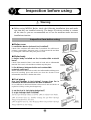
I
Terminology
The following captioned terminology has been used so that efficient handling together
with safety may be made.
Please use the Boiler after understanding captioned terminology fully.
Warning
In case of incorrect handling it may cause the user to be
killed or injured seriously.
Attention
In case of incorrect handling it may cause the user to be
injured or incur material damage.
Note
In case convenient matters and points are explained in order
to prevent the trouble of machine body and carry out
efficient work.
Meaning of sysmbol mark
Page
Prohibition
The number beside this mark displays related page.
This mark displays prohibition.
Specific prohibition contents in the middles of this code and
near it are displayed.
2
■The terminalogies that have been used in this manual are collected and check the them
and their meaning.
Terminology
Meaning
Practical Use
Under gas leakage inspection Action of inspecting inside leakage of gas V/V.
Gas
Dur water supply The condition of supplying water into the inside of boiler.
Gas, Oil
Operation standby The condition of completing prior action in order that boiler operation may be made. Gas, Oil
Pre purge
Ventilation of inside of combustion chamber before starting combustion.
Gas, Oil)
Ignition try
Condition of ignition trans operating
Oil
The condition of fire of burner.
Gas
Ignition of main burner.
Gas
Pilot ignition
Main try
Low combustion The condition of 50% combustion of maximum combustion capacity.
Gas, Oil
High combustion The condition of combustion of maximum combustion capcity.
Gas, Oil
In oder to restrict gas pressure change at the time of stop at high fire,
stopping without low fire.
Gas
Post purge
Ventilation of inside of combustion chamber after combustion.
Gas, Oil
Low water
When designated water level is not reached, an action without transition to ignition. Gas, Oil
Post fire
Combustion standby The condition of operation standby due to isolation by pressure.
Gas, Oil
Attached substances impurities such as calcium and magnesium contaied in the water.
Gas, Oil
Impurities sunk in boiler inside.
Gas, Oil
Raw water
The water before water treatment.
Gas, Oil
Soft water
The water removed from calcium and magnesium contained in the water.
Gas, Oil
Feed water
The water to be treated and trasferred to boiler or the condition of water transferring. Gas, Oil
Scale
Sludge
Rated evaporation Amount per 1 hour of full steam to be made from supplied water.
Gas, Oil
Carry-over
The phenomenon that impurites and moisture in boiler water together with steam are given off. Gas, Oil
Blowdown
Draining the water in boiler inside.
Gas, Oil
Water tube
Tube that boiler water flows in inside and is in contact with combustion gas.
Gas, Oil
O2 LIMBER
System heating the supplied water to reduce O 2¸ melted in the water.
Gas, Oil
Mixed influx of air The condition that P/P is not operated normally with influx of air into P/P.
3
Gas, Oil
II
Using purpose and operation principle
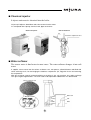
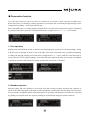
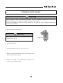
■`Once-through boiler
The boiler water pushed into the pipe is heated by burner combustion.
The heated water evaporates into steam and supplied to the load.
Once-through boiler
Water
급수valve
밸브
연료
Fuel valve
밸브
원전변valve
전원
Safety
브레이커
Breaker차단기power supply
연료
Fuel
■`Boiler chamber and steam flow
Drainpipe
Heat
exchanger
Softening
Steam leather
Water tank
Boiler
Trap
Steam condensation
Water softener
Reaction inside the boiler
Chemical injector
water line
steam line
drain line
4
Chemical injector
(food line steam condenser)
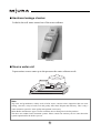
■`Chemical injector
It injects anticorrosive chemical into the boiler.
It injects pH adjuster, deoxidizer and scale remover into the water.
It is composed of the pump, chemical tank, pipes and valves.
Chemical injector
How to deaerate
Air
Deaeration adjustment valve
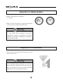
■`Water softener
The source water is hard water in most cases. The water softener changes it into soft
water.
It supplies source water into the column of about 1mm, transparent, yellowish-brown and filled with
cation exchange resin, ion-exchanging the hardness components (Ca, Mg) with Na ion and removing
the components.
With ion exchange capacity retained and due to the brine in the salt container, the cation exchange
resin gives regular regenerations. The resin needs to be replaced or added when it is deteriorated.
Cation exchange resin
Magnified resin
Column
Ion
exchange
resin
Pebble
Catchment
pipe
5
Brine tank
Salt
Brine
■`Hardness leakage checker
It checks the soft water treated out of the water softener.
Colormetry
■`Source water unit
It pressurizes source water up to the pressure the water softener needs.
Source water unit
Note
Tap water and groundwater, widely used as boiler water, contain various impurities that can cause
scaling, corrosion, carryover and so on and greatly affect their lifespan and efficiency. This is why a
water treatment system for water quality management is necessary.
Miura Boiler manufactures types of water treatment devices fitting into its boiler products.
The above are standard water treatment systems. Please consult our warranty service center about the
systems optimized for the boilers you use.
6
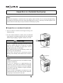
III
Basic careful matters
Warning
● When operating MIURA Boiler, observe all of the following careful matters.
If not observed, personal accident may take place.
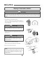
Careful matters before using the boiler
Check the installation condition.
Be sure to carry out a trial operation.
Check that the
machine has been
installed accurately
according to the
inspection before
using.
Carry out a trial
operation by a
person in charge of
A/S after checking
the installation.
☞ 28page
Be sure to designate a person in
charge of handling the boiler.
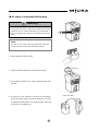
Don’t misuse the boiler.
Never operate the
machine and do not
repair work until this
manual is understood
fully.
When using the
machine, be sure to
designate a person
responsible for
handling and the
person use it after
understanding this
manual fully.
Never use boiler water as dringking one.
Report are required when using the
boiler.
Since the boiler water
can be changed by
used water quality
and piping materials,
never use it as drink
one.
In using the boiler
various reports are
required. Consult a
person in charge of
our marketing staff
for the detailed
matters.
7
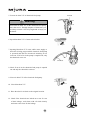
Warning
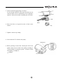
Simple clothes and wearing of protective devices
Do work in simple clothes.
Wear protective devices.
Never operate the machine and do not repair
work throngh wearing loose clothes,
accessories, etc. easily to be caught on valves
and machine parts.
Never wear the clothes attached with oils
likely to catch a fire.
Wear helmet, protective glasses, safety shoes,
gloves, etc.
According to work. In particular, when
injecting chemicals, wear protective glasses
and rubber gloves so that the hands and eyes
may not be in contact with them.
8
Warning
● When operating MIURA Boiler, observe all of the following careful matters.
If not observed, personal accident may take place.
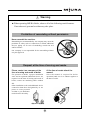
When an abnormality is found out
When an abnormality such as abnormal sound, smell, smoke, fuel leakage, etc. is found out, lock
up fuel valve directly after turning operation S/W as “OFF”. A danger such as a fire or a blast may
take place.
Abnormality handling
Observe the instruction of our
company on abnormality handling.
Never use the machine in the state
that the cause for abnormality has
not been removed fully, which may
lead to dangerous fire, blast, etc.
Inflammables or use of fire
strictly prohibited with a
gas leak
Open the windows or doors and
let some fresh air in.
Do not use switch on ventilation
fan, can cause explosion
9
Warning
Careful matters when using the boiler
Strict separation of boiler fuel from
inflammable substances
Use designated fuel.
In case of using other
fuel than designated
one a blast may take
place.
In case boiler fuel is
placed near inflammable
materials a fire may
break out.
Never place
inflammable substances
near the boiler.
Never place
inflammable substances
inside a control box.
Use ventilation equipment (exhaust
fan) when operating
When operating,
make an operation
together with
ventilation and don’t
close ventilation port.
Intoxication of carbon
monoxide by
incomplete
combustion may take
place.
Never touch the boiler thoughtlessly
when operating.
Don’t touch other part
than operation one when
operating the machine,
which may cause
dangerous electric
shock, scald, etc.
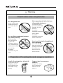
Preparation of fire extinguisher and emergency medicine
Prepare a box for emergency
medicine.
Install a fire extinguisher without fail.
In preparation for any
emergency, install a
fire extinguisher and
understand its using
method.
Designate the storing
place of emergency
medicine box and
prepare it.
10
Warning
● When operating MIURA Boiler, observe all of the following careful matters.
If not observed, personal accident may take place.
Prohibition of remodeling without permission
Never remodel the machine.
Remodeling not recommended by our company may cause the
problems in safety such as connection to related additional
devices, piping. etc. In case of remodeling, consult our A/S
staff in advance.
Our company is not responsible for the remodeling without
our prior approval.
Request at the time of moving and resale
Please contact our company at the
time of moving and resale of boiler.
At the time of resale attach the
manual.
For operation of boiler, a proper installation
work and an optimum additional device are
required. At the time of moving and resale of
boiler, contact our marketing office without
fail.
Other installation work and additional device
connection than those designated by us are
prone to cause personal
accident so you had better
not do that for the safety.
Since the manual is required for boiler
operation, hand over it to enduser together at
the time of resale.
11
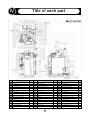
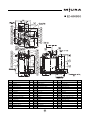
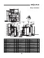
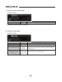
IV
Title of each part
■`EZ-500GO
No
Qt’y
No
Qt’y
No
1
Boiler body
Description
1
17
Electronic V/V (1)
Description
1
33
Pilot governer
1
2
Ball V/V
1
18
Main gas line
1
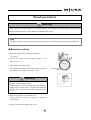
34
Control box
1
3
Bed
1
19
Gas pressure switch
1
35
Pilot Gas V/V
1
4
Inspection hole
2
20
Gas pressure gauge
1
36
Inspection hole(up)
1
5
Chimney
1
21
Pilot gas line
1
37
Exhaust Gas thermostat
1
6
Transformer
1
22
Electronic V/V (2)
1
38
Transformer
1
7
Wind box
1
23
Carry rod
2
39
Electronic V/V
3
8
Water level gauge
1
24
Flame detect hole
1
40
Oil pressure gauge
1
9
Steam pressure gauge
1
25
Guide pipe
7
41
Water line
1
10
Steam pressure S/W
1
26
Burner
1
42
Steam outlet pipe cover
1
11
Steam pressure S/W
1
27
Damper motor
1
43
Electronic V/V
1
12
Safety V/V
1
28
Blower
1
44
Oil pump motor
1
13
Combination V/V
1
29
Blower motor
1
45
Oil pump
1
14
Main Gas V/V
1
30
Water feed pump
1
46
Gas pressure switch
1
15
Main Steam V/V
1
31
Gas strainer
1
47
Electronic V/V (3)
1
16
Separator
1
32
Gas pressure switch
1
12
Description
Qt’y
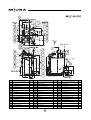
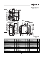
■`EZ-500SGO
No
Qt’y
No
Qt’y
No
1
Boiler body
Description
1
17
Electronic V/V (1)
Description
1
33
Pilot governer
1
2
Ball V/V
1
18
Main gas line
1
34
Control box
1
3
Bed
1
19
Gas pressure switch
1
35
Pilot Gas V/V
1
4
Inspection hole
2
20
Gas pressure gauge
1
36
Inspection hole
1
5
Economizer
1
21
Pilot gas line
1
37
Exhaust gas thermostat
1
6
Transformer
1
22
Electronic V/V (2)
1
38
Transformer
1
7
Wind box
1
23
Carry rod
2
39
Electronic V/V
3
8
Water level gauge
1
24
Flame detect hole
1
40
Oil pressure gauge
1
9
Steam pressure gauge
1
25
Guide pipe
7
41
Water line
1
10
Steam pressure S/W
1
26
Burner
1
42
Steam outlet pipe cover
1
11
Steam pressure S/W
1
27
Damper motor
1
43
Electronic V/V
1
12
Safety V/V
1
28
Blower
1
44
Oil pump motor
1
13
Combination V/V
1
29
Blower motor
1
45
Oil pump
1
14
Main Gas V/V
1
30
Water feed pump
1
46
Gas pressure switch
1
15
Main Steam V/V
1
31
Gas strainer
1
47
Electronic V/V (3)
1
16
Separator
1
32
Gas pressure switch
1
13
Description
Qt’y
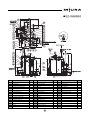
■`EZ-600GO
No
Qt’y
No
Qt’y
No
1
Boiler body
Description
1
17
Electronic V/V
Description
1
33
Pilot governer
1
2
Ball V/V
1
18
Main Gas line
1
34
Control box
1
3
Bed
1
19
Gas pressure switch
1
35
Pilot Gas V/V
1
4
Inspection hole
2
20
Gas pressure gauge
1
36
Inspection hole
1
5
Chimney
1
21
Pilot Gas line
1
37
Exhaust Gas thermostat
1
6
Transformer
1
22
Electronic V/V
1
38
Transformer
1
7
Wind box
1
23
Carry rod
2
39
Electronic V/V
3
8
Water level gauge
1
24
Flame detect hole (1)
1
40
Oil pressure gauge
1
9
Steam pressure gauge
1
25
Guide pipe
7
41
Oil pump
1
10
Steam pressure S/W
1
26
Burner
1
42
Steam outlet pipe cover
1
11
Steam pressure S/W
1
27
Damper motor
1
43
Electronic V/V
1
12
Safety V/V
1
28
Blower
1
44
Oil pump motor
1
13
Combination V/V
1
29
Blower motor
1
14
Main Gas V/V
1
30
Water feed pump
1
15
Main Steam V/V
1
31
Gas strainer
1
16
Separator
1
32
Gas pressure S/W
1
14
Description
Qt’y
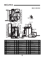
■`EZ-600SGO
No
Qt’y
No
Qt’y
No
1
Boiler body
Description
1
17
Electronic V/V
Description
1
33
Pilot governer
1
2
Ball V/V
1
18
Main Gas line
1
34
Control box
1
3
Bed
1
19
Gas pressure switch
1
35
Pilot Gas V/V
1
4
Inspection hole
2
20
Gas pressure gauge
1
36
Inspection hole
1
5
Chimney
1
21
Pilot Gas line
1
37
Exhaust Gas thermostat
1
6
Transformer
1
22
Electronic V/V
1
38
Transformer
1
7
Wind box
1
23
Carry rod
2
39
Oil seat
3
8
Water level gauge
1
24
Flame detect hole (1)
1
40
Oil pressure gauge
1
9
Steam pressure gauge
1
25
Guide pipe
7
41
Water line
1
10
Steam pressure S/W
1
26
Burner
1
42
Steam outlet pipe cover
1
11
Steam pressure S/W
1
27
Damper motor
1
43
Electronic V/V
1
12
Safety V/V
1
28
Blower
1
44
Oil pump motor
1
13
Combination V/V
1
29
Blower motor
1
14
Main Gas V/V
1
30
Water feed pump
1
15
Main Steam V/V
1
31
Gas strainer
1
16
Separator
1
32
Gas pressure switch
1
15
Description
Qt’y
■`EZ-800GO
No
Qt’y
No
Qt’y
No
1
Boiler body
Description
1
17
Electronic V/V
Description
1
33
Pilot governer
1
2
Ball V/V
1
18
Main Gas line
1
34
Control box
1
3
Bed
1
19
Gas pressure switch
1
35
Pilot Gas V/V
1
4
Inspection hole
2
20
Gas pressure gauge
1
36
Inspection hole
1
5
Chimney
1
21
Pilot Gas line
1
37
Exhaust Gas thermostat
1
6
Transformer
1
22
Electronic V/V
1
38
Transformer
1
7
Wind box
1
23
Carry rod
2
39
Electronic V/V
3
8
Water level gauge
1
24
Flame detect hole (1)
1
40
Oil pressure gauge
1
9
Steam pressure gauge
1
25
Guide pipe
7
41
Oil pump
1
10
Steam pressure S/W
1
26
Burner
1
42
Steam outlet pipe cover
1
11
Steam pressure S/W
1
27
Damper motor
1
43
Electronic V/V
1
12
Safety V/V
1
28
Blower
1
44
Oil pump motor
1
13
Combination V/V
1
29
Blower motor
1
14
Main Gas V/V
1
30
Water feed pump
1
15
Main Steam V/V
1
31
Gas strainer
1
16
Separator
1
32
Gas pressure switch
1
16
Description
Qt’y
■`EZ-800SGO
No
Qt’y
No
Qt’y
No
1
Boiler body
Description
1
17
Electronic V/V
Description
1
33
Pilot governer
1
2
Ball V/V
1
18
Main Gas line
1
34
Control box
1
3
Bed
1
19
Gas pressure switch
1
35
Pilot Gas V/V
1
4
Inspection hole
2
20
Gas pressure gauge
1
36
Inspection hole
1
5
Chimney
1
21
Pilot gas line
1
37
Exhaust gas thermostat
1
6
Transformer
1
22
Electronic V/V
1
38
Transformer
1
7
Wind box
1
23
Carry rod
2
39
Electronic V/V
3
8
Water level gauge
1
24
Flame detect hole (1)
1
40
Oil pressure gauge
1
9
Steam pressure gauge
1
25
Guide pipe
7
41
Oil line
1
10
Steam pressure S/W
1
26
Burner
1
42
Steam outlet pipe cover
1
11
Steam pressure S/W
1
27
Damper motor
1
43
Electronic V/V
1
12
Safety V/V
1
28
Blower
1
44
Oil pump motor
1
13
Combination V/V
1
29
Blower motor
1
14
Main Gas V/V
1
30
Water feed pump
1
15
Main Steam V/V
1
31
Gas strainer
1
16
Separator
1
32
Gas pressure S/W
1
17
Description
Qt’y
■`EZ-1000GO
Qt’y
No
Qt’y
No
1
Boiler body
1
17
Bed
1
33
Steam outlet pipe cover
1
2
Carry rod
2
18
Chimney
1
34
Electronic V/V
1
3
Transformer
2
19
Wind box
1
35
Oil pump motor
1
4
Exhaust gas thermostat
1
20
Inspection hole(up)
1
36
Wind pressure S/W
1
5
Control box
1
21
Flame detect hole (1)
1
37
Electronic V/V (3)
1
6
Safety V/V
1
22
Pilot burner
1
38
Pilot Gas line
1
7
Main Steam V/V
1
23
Guide pipe
7
39
Gas pressure gauge
1
8
Gas pressure switch
1
24
Burner
1
40
Gas pressure S/W
1
9
Steam pressure switch
2
25
Oil pump
1
41
Main gas line
1
10
Combination V/V
1
26
Separator
1
42
Electronic V/V (1) (2)
1
11
Steam pressure gauge
1
27
Water feed pump
1
43
Main gas V/V
1
12
Water level gauge
1
28
Blower motor
1
13
Electronic V/V
3
29
Blower
1
14
Ball V/V
1
30
Damper motor
1
15
Ball V/V
1
31
Gas pressure switch
1
16
Inspection hole
2
32
Gas strainer
1
No
Description
Description
18
Description
Qt’y
■`EZ-1000SGO
No
Qt’y
No
Qt’y
No
1
Boiler body
1
17
Bed
1
33
Steam outlet pipe cover
1
2
Carry rod
2
18
Chimney
1
34
Electronic V/V
1
3
Transformer
2
19
Wind box
1
35
Pilot burner
1
4
Exhaust Gas thermostat
1
20
Inspection hole
1
36
Wind pressure S/W
1
5
Control box
1
21
Flame detect hole (1)
1
37
Electronic V/V (3)
1
6
Safety V/V
1
22
Flame detect
1
38
Pilot Gas line
1
7
Main Steam V/V
1
23
Guide pipe
7
39
Gas pressure gauge
1
8
Gas pressure switch
1
24
Burner
1
40
Gas pressure S/W
1
9
Steam pressure S/W
2
25
Oil pump motor
1
41
Main gas line
1
10
Combination V/V
1
26
Separator
1
42
Electronic V/V (1) (2)
1
11
Steam pressure gauge
1
27
Water feed pump
1
43
Main Gas V/V
1
12
Water level gauge
1
28
Blower motor
1
13
Electronic V/V
3
29
Blower
1
14
Ball V/V
1
30
Damper motor
1
15
Ball V/V
1
31
Gas pressure switch
1
16
Inspection hole
2
32
Gas strainer
1
Description
Description
19
Description
Qt’y
■`EZ-1500GO
No
Qt’y
No
Qt’y
No
Description
1
Boiler body
Description
1
17
Wind box
Description
1
33
Electronic V/V (1) (2)
1
2
Carry rod
3
18
Inspection hole
1
34
Gas strainer
1
3
Transformer
2
19
Flame detect hole
1
35
Pilot governer
1
4
Exhaust gas thermostat
1
20
Burner
1
36
Pilot burner
1
5
Control box
1
21
Guide pipe
8
37
Wind pressure S/W
1
6
Safety V/V
1
22
Water strainer
1
38
Combination V/V
1
7
Main Steam V/V
1
23
Separator
1
39
Gas pressure S/W
1
8
Gas pressure S/W
3
24
Water feed pump
1
40
Gas pressure S/W
1
9
Steam pressure S/W
1
25
Blower motor
1
10
Steam pressure S/W
1
26
Blower
1
11
Steam pressure gauge
1
27
Damper motor
1
12
Water level gauge
1
28
Oil pump motor
1
13
Oil pressure gauge
1
29
Oil pump
1
14
Inspection hole
2
30
Steam outlet pipe cover
1
15
Bed
1
31
Electronic V/V (3)
1
16
Chimney
1
32
Gas pressure S/W
1
20
Qt’y
■`EZ-1500SGO
No
Qt’y
No
Qt’y
No
Description
1
Boiler body
Description
1
17
Wind box
Description
1
33
Electronic V/V (1) (2)
1
2
Carry rod
3
18
Inspection hole
1
34
Gas strainer
1
3
Transformer
2
19
Flame detect hole
1
35
Pilot governer
1
4
Exhaust gas thermostat
1
20
Burner
1
36
Pilot Burner
1
5
Control box
1
21
Guide pipe
8
37
Wind pressure S/W
1
6
Safety V/V
1
22
Separator
1
38
Combination V/V
1
7
Main Steam V/V
1
23
Water strainer
1
39
Gas pressure S/W
1
8
Electronic V/V
3
24
Water feed pump
1
40
Gas pressure S/W
1
9
Steam pressure S/W
1
25
Blower motor
1
10
Steam pressure S/W
1
26
Blower
1
11
Steam pressure gauge
1
27
Damper motor
1
12
Water level gauge
1
28
Oil pump motor
1
13
Oil pressure gauge
1
29
Oil pump
1
14
Inspection hole
2
30
Steam outlet pipe cover
1
15
Bed
1
31
Electronic V/V (3)
1
16
Economizer
1
32
Gas pressure S/W
1
21
Qt’y
■`EZ-2000GO
No
Qt’y
No
Qt’y
No
0
Boiler Assembly
Description
1
16
Damper motor
Description
1
32
Oil pump motor
1
1
Chimney
1
17
Flame detector
1
33
Electronic V/V (1) (2)
1
2
Seperator
1
18
Transformer
1
34
Wind pressure S/W
1
3
Main steam V/V
1
19
Flame detect hole
1
35
Gas pressure S/W
1
4
Wind box
1
20
Electronic V/V
3
36
Gas pressure gauge
1
5
Carry rod
2
21
Boiler body
1
37
Gas pressure S/W
1
6
Safety V/V
1
22
Water level gauge
2
38
Gas pressure S/W
1
7
Transformer
1
23
Inspection hole
3
8
Burner
1
24
Steam pressure gauge
1
9
Pilot Gas V/V
1
25
Steam pressure S/W
1
10
Bed
1
26
Steam pressure S/W
1
11
Gas strainer
1
27
Control box
1
12
Pilot governer
1
28
Oil pump
1
13
Blower
1
29
Ladder
1
14
Blower motor
1
30
Exhaust Gas thermostat
1
15
Water feed pump
1
31
Electronic V/V (3)
1
22
Description
Qt’y
■`EZ-2000SGO
No
Qt’y
No
Qt’y
No
0
Boiler Assembly
Description
1
16
Damper motor
Description
1
32
Electronic V/V (3)
1
1
Economizer
1
17
Flame detector
1
33
Oil pump motor
1
2
Seperator
1
18
Transformer
1
34
Electronic V/V (1) (2)
1
3
Main steam V/V
1
19
Flame detect hole
1
35
Wind pressure S/W
1
4
Wind box
1
20
Electronic V/V
3
36
Gas pressure S/W
1
5
Carry rod
2
21
Boiler body
1
37
Gas pressure gauge
1
6
Safety V/V
1
22
Water level gauge
2
38
Gas pressure S/W
1
7
Transformer
1
23
Inspection hole
3
8
Burner
1
24
Steam pressure gauge
1
9
Pilot Gas V/V
1
25
Steam pressure S/W
1
10
Bed
1
26
Steam pressure S/W
1
11
Gas strainer
1
27
Control box
1
12
Pilot governer
1
28
Gas pressure S/W
1
13
Blower
1
29
Oil pump
1
14
Blower motor
1
30
Ladder
1
15
Water feed pump
1
31
Exhaust Gas thermostat
1
23
Description
Qt’y
■`EZ-2500GO
No
Qt’y
No
Qt’y
No
0
Boiler Assembly
Description
1
16
Damper motor
Description
1
32
Electronic V/V (3)
1
1
Chimney
1
17
Flame detector
1
33
Oil pump motor
1
2
Seperator
1
18
Transformer
1
34
Electronic V/V (1) (2)
1
3
Main steam V/V
1
19
Flame detect hole
1
35
Wind pressure S/W
1
4
Wind box
1
20
Electronic V/V
3
36
Gas pressure S/W
1
5
Carry rod
2
21
Boiler body
1
37
Gas pressure gauge
1
6
Safety V/V
1
22
Water level gauge
2
38
Gas pressure S/W
1
7
Transformer
1
23
Inspection hole
3
8
Burner
1
24
Steam pressure gauge
1
9
Pilot Gas V/V
1
25
Steam pressure S/W
1
10
Bed
1
26
Steam pressure S/W
1
11
Gas strainer
1
27
Control box
1
12
Pilot governer
1
28
Gas pressure S/W
1
13
Blower
1
29
Oil pump
1
14
Blower motor
1
30
Ladder
1
15
Water feed pump
1
31
Exhaust gas thermostat
1
24
Description
Qt’y
■`EZ-2500SGO
No
Qt’y
No
Qt’y
No
0
Boiler Assembly
Description
1
16
Damper motor
Description
1
32
Electronic V/V (3)
1
1
Economizer
1
17
Flame detector
1
33
Oil pump motor
1
2
Seperator
1
18
Transformer
1
34
Electronic V/V (1) (2)
1
3
Main steam V/V
1
19
Flame detect hole
1
35
Wind pressure S/W
1
4
Wind box
1
20
Electronic V/V
3
36
Gas pressure S/W
1
5
Carry rod
2
21
Boiler body
1
37
Gas pressure gauge
1
6
Safety V/V
1
22
Water level gauge
2
38
Gas pressure S/W
1
7
Transformer
1
23
Inspection hole
3
8
Burner
1
24
Steam pressure gauge
1
9
Pilot Gas V/V
1
25
Steam pressure S/W
1
10
Bed
1
26
Steam pressure S/W
1
11
Gas strainer
1
27
Control box
1
12
Pilot governer
1
28
Gas pressure S/W
1
13
Blower
1
29
Oil pump
1
14
Blower motor
1
30
Ladder
1
15
Water feed pump
1
31
Exhaust gas thermostat
1
25
Description
Qt’y
■`EZ-3000GO
No
Qt’y
No
Qt’y
No
0
Boiler Assembly
Description
1
16
Flame detector
Description
1
32
Ball V/V
1
1
Boiler body
1
17
Exhaust Gas thermostat
1
33
Niddle V/V
1
2
Control box
1
18
Transformer
1
34
Pilot Gas V/V
1
3
Seperator
1
19
Flame detect hole
1
35
Transformer
1
4
Bed
1
20
Electrode rod
1
36
Gas pressure S/W
1
5
Electronic V/V
3
21
Ladder
1
37
Oil pump motor
1
6
Water feed pump
1
22
Gas strainer
1
38
Gas pressure gauge
1
7
Blower
1
23
Main Steam V/V
1
39
Pilot governer
1
8
Blower motor
1
24
Water level gauge
1
40
Electronic V/V (1) (2)
1
9
Inspection hole
3
25
Water strainer
1
41
Gas pressure S/W
1
10
Carry rod
2
26
Carry rod
1
42
Oil burner
1
11
Safety V/V
1
27
Thermometer
1
43
Wind pressure S/W
1
12
Wind box
1
28
Steam pressure S/W
2
44
Electronic V/V (3)
1
13
Damper motor
1
29
Oil pump
1
45
Gas burner
1
14
Guide pipe
10
30
Steam pressure gauge
1
46
Gas pressure S/W
1
15
Flame detect hole
1
31
Ball V/V
1
26
Description
Qt’y
■`EZ-3000SGO
No
Qt’y
No
Qt’y
No
0
Boiler Assembly
Description
1
16
Flame detector
Description
1
32
Ball V/V
1
1
Boiler body
1
17
Exhaust Gas thermostat
1
33
Niddle V/V
1
2
Control box
1
18
Transformer
1
34
Pilot Gas V/V
1
3
Seperator
1
19
Flame detect hole
1
35
Transformer
1
4
Bed
1
20
Electrode rod
1
36
Gas pressure S/W
1
5
Electronic V/V
3
21
Ladder
1
37
Oil pump motor
1
6
Water feed pump
1
22
Gas strainer
1
38
Gas pressure gauge
1
7
Blower
1
23
Main Steam V/V
1
39
Pilot governer
1
8
Blower motor
1
24
Water level gauge
1
40
Electronic V/V (1) (2)
1
9
Inspection hole
3
25
Water strainer
1
41
Gas pressure S/W
1
10
Carry rod
2
26
Economizer
1
42
Oil burner
1
11
Safety V/V
1
27
Thermometer
1
43
Wind pressure S/W
1
12
Wind box
1
28
Steam pressure S/W
2
44
Electronic V/V (3)
1
13
Damper motor
1
29
Oil pump
1
45
Gas burner
1
14
Guide pipe
10
30
Steam pressure gauge
1
46
Gas pressure S/W
1
15
Flame detect hole
1
31
Ball V/V
1
27
Description
Qt’y
V
Inspection before using
Warning
● Before using MIURA Boiler, check the following installation item and make
sure that they are installed correctly. The danger of serious accident is existent
all the time so you are recommended not to use the machine under incorrect
installation situation.
Inspection item before using
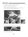
■`Boiler room
Is ventilation device (exhaust fan) installed?
Check if the ventilator and exhaust fan are installed. If a sufficiant air
exhaust is unavailable, dangerous toxic of carbon monoxide and blast
by incomplete combustion may take place as well.
Ventilator
Exhaust device
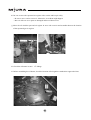
■`Boiler body
Is boiler body installed on the incombustible material
base?
Check if the material of base is not made of wood such as inflammable
material. If it is used, a fire and other accidents may take place.
Is the distance between boiler and combustible
materials sufficient?
Inflammable
material
r
the
Far
n
a
th
Boiler installation shall not be made in the inflammable and dangerous
material handling place and make sure that the distance from
inflammable materials is farther than 45cm.
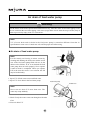
■`Fuel piping
Any fuel leakage in fuel piping? Longer than 2m in
horizontal distance between oil tank and boiler?
If not snfficient in horizontal distance between oil tank and boiler an
explosion is likely to take place dangerously.
Is not the fuel in fuel piping leaked out?
Is a gas leakage alarm installed?
Install a gas leakage alarm in LPG or LNG for exlusive use boiler.
LPG is heavier than air, thereby causing the gas blast through
being accumulated on the floor.
LNG is lighter than air, thus bringing about the gas blast through
being collected on the ceiling.
28
Inflammable material
Farther
than
Warning
Electric leakage
breakera
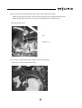
■`Electric work
If warning matters on electric work are not observed,
it may lead to electric shock or other serious accident.
Electric leakage
breakera
Breaker
capacity
Is power source only for boiler?
Make sure that an exclusive use breaker as power
source of boiler is attached.
Is electric leakage breaker attached?
Check if a breaker attached to main power source is
an electric leakage one.
Wiring
Do you use designated product for cable
thickness?
Check if cable thickness and breaker capacity are in
accordance with designated specification or not.
Is ground wiring connected to earth
terminal?
Earth
terminal
Make sure that ground wiring is connected to earth
terminal inside a boiler control box.
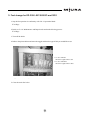
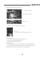
■`Installation of exhaust tub
Is penetration part of exhaust tub
composed of incombustible materials?
Exhaust tub
Make sure that penetration part of exhaust tub is
composed of incombustible materials. If it is composed
of combustible materials a fire may take place..
Are combustible materials not near the
circumference of exhaust tub?
Check if inflamable materials are not near the
circumference of exhaust tub. If they are existent
nearby, it may be the cause for a fire.
Is the connection part airtighted and fixed
securely?
Check if airtightness and fixation of it are made fully
or not. If not, a toxication accident by exhaust gas
leakage may take place.
29
Incombustible
materials
Warning
● Before using MIURA Boiler, check the following installation item and make
sure that they are installed correctly. The danger of serious accident is existent
all the time so you are recommended not to use the machine under incorrect
installation situation.
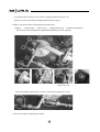
■`Safety V/V discharge piping
Is there not any danger in the direction of the
discharge piping end?
Make sure that the direction is not dangerous to people
even though hot water is discharged at the discharge
piping end?
If the end of piping is toward people there is a danger of a
burn and other accidents at the time of hot water
discharge.
Safety V/V
Discharge
piping
Does the discharge piping not move with
reaction by discharging?
Make sure that the discharge piping is fixed securely. If
not, the piping will move with reaction by discharging,
thereby causing a burn and other accidents at the time of
hot water discharge from piping.
■`Blow piping
Does piping not move with reaction by blow
water?
Checking if piping is fixed securely or not. If not, the
piping will move with reaction by discharging, thereby
causing a burn and other accidents at the discharge of hot
water discharge from piping.
Is the end opened to safe place such as bit
and etc?
Check if the end of drain piping is opened to safe place
such as a bit and etc.
If the end of piping is installed in the place without drain
device, the hot water discharge when draining the water
may cause a scald and other accidents.
30
Drain piping
Bit
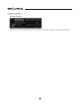
VI
Using method of operation system
Title and function of S/W
Remote control display lamp
Under reservation operation display lamp
Under fire display lamp
Power lamp
OPERATION S/W
Turing S/W as “ON”,
water level control and
chemicals injection
one are started.
FIRE S/W
Boiler fire / fire stop S/W
MODE CHANGE S/W
Mode change S/W such as item change S/W of monitor, warning
record, thermal control, operation setting, time setting, test mode
RESERVATION
Reservation time setting is made with reservation setting S/W in time setting
mode and reservation cancellation is made by pushing RESERVATION again
or operation S/W.
RESET
When warning or alarm is generated a buzzer stops by one time operation and if one
more OPERATION is mode RESET is made.
SETTING
When the selection and change of data rare fixed at mode of OPERATION setting and time
setting the selection and change are fixed by setting S/W operation.
OPERATION INSTRUCTION
In case a warning or an alarm is generated the matter to be taken properly to the situation while pushing
the S/W are displayed.
NOTE
LCD protection function: In case LCD operation is not made for one hour the screen is
offthrough activation of LCD protection function. When LCD
screen isOFF it is ON by pushing any operation key.
31
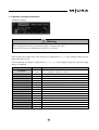
Display contents of monitor
BLOW
At blow time it is lit up and
during blow it is lit off.
ALARM
When alarm matters are generated it is lit up.
WARNING
When warning matters are generated it lit off.
MONITOR
Change to MONITIR WARNING
record, themal control, operation
setting, time setting and test by
◁, ▷ change
Display of present day and time
Condition of present monitoring item
Display of boiler operation/stop condition
Display of boiler operation condition
Display of using fuel selection (decided by ROM)
Water level graph (display of present water level)
Display as 3 ea bars graph by each electrode
Low water level location
32
Operation of controller and its using method
▶
Monitor
Warning record
▶
Thermal control
▶
▶
Operation setting
Time setting
▶
Test
▶
1. Item change is made by drection key ◁, ▷ operation.
2. Item change is made by direction key △, ▽ operation.
Note) In case operation setting and test mode are under operation
the setting is impossible.
■`Contents of each mode
1. Contents of monitor mode
-Example of display-
Monitor item
Scale monitor
Contents
。
C
Displays the temp. of scale sensor within water tube.
Overheat monitor temp
。
C
Displays the temp. of overheat sensor within water tube.
Condensed blow
ON/OFF
2. Contents of thermal control
-Example of display-
Monitor item
Fule consumption
Contents
Nm³
Displays fuel consumption amount through integrating.
Evaporation
t
Displays evaporated water amount through integrating.
High fire time
min
Displays fire time with high fire through integrating.
Displays fire time with low fire through integrating.
Low fire time
min
Ignition times
times
Displays ignition times through integrating.
Feed water pump ON/OFF times
times
Displays feed water pump ON/OFF times through integrating.
※ For thermal control item one day is integrated.
33
3. Warning record
-Example of display-
Note) In case a warning is generated, recent 10 items are stored at warning record mode automatically.
34
4. Operation setting and contents
-Example of display-
Warning
When changing the contents of operation setting, consult our A/S office.
It may be the cause for a malfunction, fire, blast, etc. of boiler.
After selecting the change item with setting one in application of △‚▽ S/W, pushing setting S/W the
changeable part is lit off.
After completing the change in application of △‚▽‚◁‚▷‚ S/W, pushing setting S/W again the setting
change is completed.
Item
MI NUMBER
Unit
Contents
Machine
When instaling multi-tubes, boiler identification number is set and in
number
case of single tube, setting as 1 is made.
SET DATE
Change day of setting data is inputted.
AUTO BLOW RATE
%
SCALE MONITOR(L)
C
1。
When low fire is made, scale attaching alarm setting temp. is set.
Condensed blow rate is set.
SCALE MONITOR(H)
1。
C
When high fire is made, scale attaching alarm setting temp. is set.
TWIN WATER LEVEL DLY
1sec
Water level delay time is set.
LOW WATER DELAY TIME
1sec
Low water level warning delay time is set.
DAMPER DELAY(L-H)
0.1s
Time from high fire electronic V/V ON to wind amount change is set.
DAMPER DELAY(H-L)
0.1s
Time from high fire electronic V/V OFF to wind amount change is set.
EVAPORATION
100kg/h
START TIME
1hour
HEAT VOLUME
10
Low level heat generation amount of using fuel is inputted.
WATER TEMP.
1
Temp. of using water is inputted.
Temp. of using fuel is inputted.
Actual evaporation amount of boiler is set.
Data renewal by every one hour from the base time of thermal control data is set.
FUEL TEMP.
1
FUEL VOLUME(L)
0.1
Fuel volume at the time of low fire is inputted.
FUEL VOLUME(H)
0.1
Fuel volume at the time of high fire is inputted.
KOREAN/ENGLISH/CHINESE
When selecting using language, one of three languages is inputted.
35
5. Contents of time setting mode
-Example of display-
Item
Unit
Month day/Time change
Hour
Contents
It is set for month day/time change of monitor.
※ Reservation operation time is set at time setting mode.
6. Contents of test mode
-Example of display-
Item
Scope
PILOT ONLY
ON/OFF
When adjusting Fire the progressing PILOT ONLY is made.
ON/OFF
When adjusting Fire LOW FIRE ONLY is made.
LOW FIRE ONLY
FAN/WP/OP
TEST OF INDIVIDUAL PART
Contents
As the function capable of outputting specific parts forcibly when
/IGT/VQ/
testing boiler the forcible output is made by selecting with ON after
VQ1/VQ2
selection of parts.
Initialization of setting
OPERATION SETTING
INITIALIZATION
value of all of datum and
Possible only if secret number is inputted.
operations in memory
36
■`Reservation function
For reservation function, the reservation is possible by two kinds of time operation/weekday one.
Reservation time is set ahead by selecting operation by reservation time or weekday through moving to time
setting item by pushing ▷ S/W in the monitor state.
Since changeable part is lit off by pushing setting S/W for reservation time setting, time setting is completed
by pushing setting S/W again after setting the desired time in application of ▽, △, ◁, ▷ arrow marks.
1. Time operation
Pushing reservation S/W the screen as shown in the following figure in the left is seen and pushing a setting
S/W the screen is changed as shown in one in the right. Four times reservation a day is possible and pushing
a setting S/W through checking reservation time in application of ▽, ▷ arrow mark the reservation lamp is
lit up in the left of LCD. When pushing a reservation S/W once again at the time of reservation cancellation
or pusing an operation S/W during reservation operation the reservation is cancelled.
2. Weekday operation
Pushing setting S/W after pushing a reservation S/W and selecting weekday operation the condition as
shown in the following figure in the right is made and pushing a setting S/W after checking reservation time
the reservation is completed and the reservation lamp is lit up. When cancelling the reservation it is cancelled
by pushing a reservation S/W once again or pushing an operation S/W during reservation operation.
37
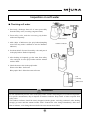
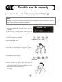
Operation of main steam V/V
Warning
Since main steam V/V is located at high place and its footing is limited, operate it in proper clothes(long
sleeve, long pants, safety shoes, safety helmet, gloves, etc) when switching on and off.
Since whole boiler body is in the high temperature state directly after stopping it, never touch other part
than the handle of main steam V/V. If touched, you may incur a scald and other injury.
Note
In case a steam header is being installed during piping work, open main steam V/V.
Main steam V/V of steam header plays a role of main steam V/V instead.
Install backflow prevention V/V (check V/V for steam) in steam piping between steam header and boiler.
1. Prepare a ladder.
2. Check location and direction of main steam V/V.
3. Open and close the main steam V/V on the ladder.
Warning
Never jump up and down the ladder. When going up
and down, be sure to hold the ladder with both hands
and one leg or one hand and both legs in order that
you may go up and down safely against the danger of
falling down.
Opened
Closed
38
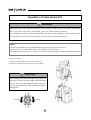
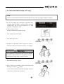
Water drain of feed water pump
Warning
For the boiler of hot water specification and drain recovery, since the water in feed water piping is hot,
do not work until the feed water piping cools down ( longer than 2 hours from the stop of boiler) fully in
order to prevent any injury such as a scald and etc.
Note
V/V of water drain and air drain in the feed water pump is somewhat different from that in
specification in some cases. Consult our A/S staff for proper use before using.
■`Water drain of feed water pump
Note
In case of solving the freezing problem by water
drain of water tube and feed water pump, do drain
work of feed water pump as follows. Drain work of
feed water pump shall be done after drain of water
tube.
Closed
Opened
1. Close V/V of water supply and feed water source.
2. Open V/V of water drain and air drain in the feed
water pump.
Feed water pump
Air drain V/V
Note
Never turn V/V of water drain and air drain more
than once. The water may eruput suddenly.
3. Check if the water does not drain from water drain
Water drain V/V
V/V.
4. Close V/V of water drain and air drain in feed water
pump.
39
Open
Close
Air drain of feed water pump
Warning
For the boiler of hot water specification and drain recovery, since the water in feed water piping is hot,
do not work until the feed water piping cools down (longer than 2 hours from the stop of boiler) fully in
order to prevent any injury such as a scald and etc.
Note
V/V of water drain and air drain in the feed water pump is somewhat different from that in
specification in some cases. Consult our A/S staff for proper use before using.
■`Air drain of feed water pump
Note
Closed
For the remedy on freezing in winter season by
cleaning and draining the feed water strainer and in
case of the feed water pump filled with air, do the
drain work as follows. If air is not drained the feed
water pump does not work properly. Never operate
it until air drain is completed. When you operate
P/P in the state that water is not existent the P/P
may be broken badly.
Opened
1. Open V/V of feed water source and feed water.
2. Open V/V of air drain in the feed water pump.
Feed water pump
Air drain V/V
Note
Never turn air drain V/V more than once. The
water may erupt suddenly.
3. Check if only the water comes out through an isloation
Water drain V/V
of air.
Open
4. Close air drain V/V
40
Close
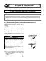
VII
Inspection and preparations before starting
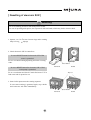
■`Check the following items before operating a boiler.
1. Check if a short circuit breaker inside a control box is
OFF or not.
If it is ON, turn it as OFF.
Warning
Don’t operate the boiler with wet hands, which may
cause an electric shock.
2. Turn main power as ON.
Warning
Don’t operate the boiler with wet hands, which may
cause an electric shock.
Note
When main power is not used for a long time, turn
it as OFF. Without it you may incur an electric
shock.
3. After opening air drain V/V of water pipe for about 5
seconds, close it.
Opened
Warning
In case even little pressure is left within the boiler
(when a steam pressure gauge marks 0kg/cm²above),
do not open air drain V/V of water pipe. If it is
opened, an eruption of steam may bring about a burn
and etc.
Opened
Opened
4. After checking if the water is filled in feed water tank
above 2/3, open V/V of feed water source and feed
water.
5. In accordance with「using method of operation system
and air drain of feed water pump」in chapter 6, drain
air from the feed water pump.
☞ 40page
41
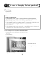
6. Confirmation of fuel
■The case which will use the gas.
Open the gas inlet valve.
Read chapter 「
9 Maintenance/gas pressure checking up」and
check whether gas pressure gauge is on the normal.
Opened
■The case which will use the oil.
Check if the fuel is filled fully in tank and open the
fuel V/V in it.
Opened
7. According to「Repair & inspection/Chemicals injection
inspection」
, check if designated amount of chemicals
is in chemicals injection TK or not.
☞ 52page
8. According to「Repair & inspection/Soft water
inspection」in chapter 9, check if feed water is made as
soft one or not.
☞ 55page
9. Check if main steam V/V is closed or not. If not
closed, close it in accordance with「Using method of
operation system/Operation of main steam V/V」in
chapter 6.
☞ 38page
Closed
10. Turn a short circuit breaker within a control box as
ON.
Warning
Don’t operate the boiler with wet hands, which may
cause an electric shock.
42
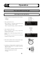
VIII
Operation
The case which use the gas
Starting(normal operation)
1. Complete「Inspection and preparations before starting」
in chapter 7.
☞ 41page
2. Turn operation S/W as ON.
Water supply is controlled automatically and
「Operation standby」condition is made.
Check if「Operation standby」condition is made or not.
3. Turn combustion S/W as ON.
When「combustion」lamp is lit up it alarms that
combustion action is taken.
Ignition action is taken after prepurge and then low is
entered.
Low combustion is passed after main try and high
combustion is being executed.
4. Wait until an indicated value of steam pressure guage
reaches the designated pressure one(5kg/cm²
).
5. According to「Using method of operation system/
Operation of main steam V/V」in chapter 6, open main
steam V/V slowly.
By repeating low combustion and high one alternately,
supply the designated pressure steam.
☞ 38page
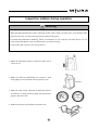
43
Opened
Stop
1. Turn fire S/W as OFF.
A fire lamp is it off.
Acoording to the condition a post fire is executed.
Thereafter a post purge is being executed.
2. Check if a post fire is completed or not.
Marking of display changes from「Post purge to
Operation standby」
.
Note
If an operation is stopped without a sufficient
purge, the gas heaped within the furnace may be
the cause for trouble.
3. Turn operation S/W as OFF.
4. Turn a short circuit breaker in a control box as OFF.
5. Turn main power as OFF.
6. Pursuant to「Using method of operation
system/Operation of main steam V/V」in chapter 6,
close main steam V/V.
Main steam V/V
☞ 38page
7. Close V/V of water supply, main water supply and
main gas.
Warning
Water supply V/V
In case of danger of freezing, take a freezing remedy
according to「Repair & inspection / Danger of
freezing」in chapter 9.
In case of stop for a long time, see「Repair &
inspection / Standstill for a long time」in chapter 9.
44
Main gas V/V
Closed
Inspection matters during operation
Warning
When abnormal phenomenon such as abnormal sound, smell, smoke, etc takes place, turn operation S/W
OFF and close fuel V/V. Fire and explosion are likely to take place.
For abnormal phenomenon handling, follow an instruction of our company A/S staff. Never use our
boiler in the state that the cause for abnormality is not removed fully.
It may lead to the cause for a fire and explosion.
1. Make sure that black smoke or white one comes out of
a stack or not.
2. Make sure that any abnormality of a blower, a feed
water pump, etc in operation sound is present or not.
Vibration
3. Make sure that serious vibration or abnormal value in
an indicator of steam pressure gauge and oil pressure
gauge is present or not.
4. Make sure that any fuel leakage is present or not.
Gas
45
Gas
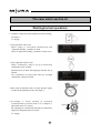
The case which use the oil
Starting(normal operation)
1. Complete「Inspection and preparations before starting」
in chapter 7.
☞ 41page
2. Turn operation S/W as ON.
Water supply is controlled automatically and
「Operation standby」condition is made.
Check if「Operation standby」condition is made or not.
3. Turn combustion S/W as ON.
When「combustion」lamp is lit up it alarms that
combustion action is taken.
Ignation action is taken after prepurge and then low is
entered.
Low combustion is passed after main try and high
combustion is being executed.
4. Wait until an indicated value of steam pressure guage
reaches the designated pressure one(5kg/m²
).
5. According to Using method of operation
system/Operation of main steam V/V in chapter 6,
open main steam V/V slowly.
By repeating low combustion and high one alternately,
supply the designated pressure steam.
☞ 38page
46
Opened
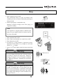
Stop
1. Turn combustion S/W as OFF.
The combustion lamp is lit off. According to the
condition post fire is executed. Thereafter post purge is
being executed.
2. Check if post purge is completed or not.
Marking of display changes from「Post purge」to
「Operation standby」
.
Note
If an operation is stopped without a sufficient post
purge, the gas heaped within the furnace may be
the cause for trouble.
3. Turn operation S/W as OFF.
4. Turn a short circuit breaker in a control box as OFF.
5. Turn main power as OFF.
6. According to「Using method of operation system/
Operation of main steam V/V」in chapter 6, close main
steam V/V. ☞ 47page
7. Close V/V of water supply, main feed water, main feed
oil.
Warning
In case of danger of freezing, take a freezing remedy
according to「Repair & inspection / Danger of
freezing」in chapter 9. In case of stop for a long time,
see「Repair & inspection / Standstill for a long time」
in chapter 9.
Warning
Main Steam V/V
Feed water pump
For operation of fuel V/V, operate only fuel V/V of
oil tank. If closing other V/V than that of oil tank
since an oil in fuel piping is expanded by discharging
heat of boiler body directly after boiler stop, there is
some danger of the damage in oil P/P and that of the
leakage in fuel oil.
47
Close
Inspection matters during operation
Warning
When abnormal phenomenon such as abnormal sound, smell, smoke, etc takes place, turn operation S/W
OFF and close fuel V/V. Fire and explosion are likely to take place.
For abnormal phenomenon handling, follow an instruction of our company A/S staff. Never use our
boiler in the state that the cause for abnormality is not removed fully.
It may lead to the cause for a fire and explosion.
1. Make sure that black smoke or white one comes out of
a stack or not.
2. Make sure that any abnormality of a blower, a feed
water pump, etc in operation sound is present or not.
3. Make sure that serious vibration or abnormal value in
an indicator of steam pressure gauge and oil pressure
guage i present or not.
4. Make sure that any fuel leakage is present or not.
48
IX
Repair & inspection
In case of possible destruction by freezing
Note
The following instructional freezing remedy is an example. According to the regional situations boiler
installation, take a comprehensive freezing remedy including circumferential instruments. For the
freezing remedy, consult our A/S office freely any time.
■`A freezing remedy by drain of water tube and water supply P/P
1. Stop an operation according to「Starting / Stop」in
chapter 8.
☞ 43page
2. Wait until the display of a steam pressure gauge
reaches 0to 2kg/cm²
.
3. Open V/V of a water tube blow slowly and blow the
water tube.
4. When a steam pressure gauge exceeds 2kg/cm²
, do not
open V/V of the water tube blow.
Blow V/V
Warning
Each part of boiler is made of hot temp. materials.
Never touch other part than water tube blow V/V,
which may cause a scald.
Do not open water tube blow V/V abruptly, which
may lead to a burn by means of abrupt eruption of hot
water.
Check if blow piping is fixed securely in order that it
may not be moved by any reaction of blow.
Check if the end of blow piping is opened to safe
place such as a bit and etc.
5. Close V/V of the water tube blow.
6. Drain the water form feed water pump according to
「Using method of operation system / Drain of feed
water pump」in chapter 6.
☞ 39page
49
Open slowly
Close
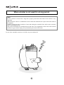
When a boiler is not used for a long period
Note
In case a boiler is not used for a long time a proper preservation and control for the boiler is very
important.
When the boiler comes to a standstill the concern about the maintenance & repair of the boiler tends to
be negligent.
Without good preservation condition of water tube during the standstill of the boiler some corrosions
may be rusted dangerously.
The preservation method is classified into the full water one in application of the water removed from
remained oxygen and the drying one by maintaining the inside of the boiler.
In case of the standstill, consult our A/S office any time without fail.
50
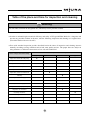
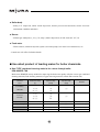
Table of the place and time for inspection and cleaning
Warning
Do not other work than the designated one, which may lead to personal accident.
`In order to maintain high economical efficiency and safety of EZ type MIURA Boiler for a long time and
prevent any possible accident in advance, take the following inspection and cleaning on a regular basis.
(Check the details with our A/S staff.)
`Even with standard inspection periods described herein the times of inspection and cleaning increase
naturally according to using condition such as bad water quality and etc. The proper times are subject to
using situations so follow the instructions of our A/S staff without fail.
Period of inspection and cleaning
Items of inspection and cleaning
Every day
Inspection chemicals feed pump
●
Inspection on a water softener
●
Inspection on steam pressure
●
Inspection on oil pressure
●
Inspection on combustion
●
1 month
Inspection on the low water level
3 months
Every year
●
warning
●
Cleaning of the water supply tank
●
inside
●
Cleaning of a water supply strainer
●
Request for water quality analysis
●
Inspertion on oil strainer
●
Cleaning of burener
●
Cleaning of oil tank
●
Inspection on safety V/V
●
Inspection on sightglass of a water level gauge
●
51
Inspection on chemicals feed pump
Note
Chemicals feed pump is essential to the water quality control of boiler. Use it correctly through reading
the manual of chemicals injection system thoroughly before using it. And keep it at hand together with
boiler manual in order that you may read them conveniently any time.
■`Inspection on remained chemicals
1. Check remained chemicals through looking into
Chemicals tank.
2. In case remined amount is small, insert an indicated
input amount of cleaning chemicals into the Chemicals
tank through weighing it together with our A/S staff.
Warning
In case of inputting chemicals, be sure to wear
protective glasses and gloves. If they are in contact
with your eyes and hands you may incur a loss of
eyesight and an injury on the hands.
If the chemicals touch your skin directly, wash it with
the flowing water immediately.
If they enter into the eyes, wash them with the
flowing water instantly and consult with a doctor as
well.
Note
Follow the instructions of our A/S staff for an input
amount of chemicals.
If you are negligent in supplimenting the
chemicals, an air enters into chemicals feed pump
to the extent that the chemicals can not be supplied
to a boiler so you are required to inspect remained
chemicals without fail.
In case of slow consumption of chemicals in the
chemicals tank the air may enter into the chemicals
feed pump so drain the air in the tank.
52
Chemicals feed pump
Chemicals
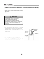
■`Air drain of chemicals feed pump
Warning
When draining an air in the chemicals feed pump,
wear protective glasses and gloves without fail. If the
chemicals are in contact with the eyes and hands a
loss of eyesight and an injury on the hands may take
place.
Note
In case an air enters into the chemicals injection
P/P, drain an air in it in the following manner.
1. Turn combustion S/W as OFF.
Chemicals
2. Check remained chemicals in the chemicals tank.
3. If remained chemicals are small, replenish them into
the tank.
4. According to the manual of chemicals feed pump,
attach one end of tube for air drain being an accessory
of chemicals feed pump to air outlet and put other end
of tube into a weighing cup.
53
Tube for air drain
5. Loosen air drain V/V of chemicals feed pump.
Air drain
Open
Warning
Never turn air drain V/V of the chemicals feed pump
more than twice. Through eruption of chemicals you
are likely to incure a loss of eyesight and an injury on
the hands.
Close
6. Open blowdown V/V of water tube in boiler.
Open
7. Opening blowdown V/V water, while water supply to
the boiler is being progressed the chemicals feed pump
is operated and then the chemicals including an air
come out. If all of air in the pump is emptied out, only
the chemicals come out.
Air
Chemicals
8. Check if an air in the chemicals feed pump is emptied
out and only the chemicals come out.
9. Close air drain V/V of the chemicals feed pump.
Close
10. Close blowdown V/V.
11. Place the tube for air drain to the original location.
12. Check if the chemicals are leaked out or not. In case
of their leakage, wash them with soft cloth cleanly
and remove the cause for the leakage.
54
Inspection on soft water
■`Checking soft water
1. Previously, discharge about 2L of water powerfully
from the safety valve (excreting congested water)
2. From safety valve, wash the accessory poly beaker
with water frequently.
3. Add 4 drips of indicator to the poly beaker(Sampling
water first may make it difficult to mix the hardness
indicator)
Cork for
Inspection testing
water
cock
Water softener
Hardness indicator
4. Get about 20mL of water from safety valve and pour it
to the poly beaker. Shake it frequently.
5. After shaking it frequently, get the water from safety
valve and pour it to the poly beaker until the amount
reaches 50mL.
6. Check the water color in the poly beaker.
Water color~Blue : Soft water
Blue purple~Red : did not become soft water
Salt
Salt lump
Saline water
Attention
Do not automatically mix the water in the poly beaker. It makes measuring the exact amount impossible.
For specific measurement, drop 4 droplets of hardness indicator. Keep 50mL of water acquired from
safety valve.
The hardness indicator should be slowly dropped with the pipette vertically positioned. After shaking
enough, get water until the amount reaches 50mL. Examine the color change immediately. After more
than 10 minutes, color change becomes dull with exact measurement failed.
55
Check for gas pressure
1. Open main gas inlet V/V.
main gas inlet V/V
2. Check gas pressure gauge on the boiler whether it’s in
the regular pressure.
3. If the value of the gas pressure guage is not the
standdard one,, stop the boiler immediately according to
chapter 8「Openration/Stop」and contact out our A/S
office.
Normal value of gas pressure
Boiler
EZ-500GO, SGO~EZ-2000GO, SGO
Gas
LNG
1000 ~ 4000mmAq
LPG
56
Inspection on oil pressure
Note
For oil pressuree inspection, do it during boiler operating. An oil P/P is operated in the state of
combustion but accurate pressure inspection is not possible if oil P/P is not operated.
1. Inspect oil pressure during boiler combustion.
Make sure that a combustion lamp is lit up.
Warning
Each part is in the state of hot temperature during
boiler operation, don’t touch it. You may suffer some
burn.
2. Make sure that marking of oil pressure gauge is rated
value or not.
Warning
In case any abnormality is present in oil pressure,
contact our A/S office after stopping an operation
immediately. If operating a boiler in the state of
abnormality of oil pressure continuonsly, some
personal accident may take place.
Rated value of oil pressure
Kind of boiler
Pressure
EZ-500GO, SGO
8kg/cm2±1
EZ-600GO, SGO
8kg/cm2±1
EZ-800GO, SGO
8kg/cm2±1
EZ-1000GO, SGO
8kg/cm2±1
EZ-1500GO, SGO
12kg/cm2±1
EZ-2000GO, SGO
15kg/cm2±1
EZ-2500GO, SGO
15kg/cm2±1
EZ-3000GO, SGO
14kg/cm2±1
57
Cleaning of burner
Warning
Since each part of boiler is hot directly after boiler stop, don’t operate the boiler until it cools down
fully(until about 2 hours after boiler stop). You may incur some scald.
Note
Since the frequency of burner cleaning changes due to the fuel usage and its condition, follow an
instruction by our A/S staff.
1. Turn main power of boiler OFF.
Warning
Don’t operate a boiler with wet hands, which may
Main power
lead to electric shock.
Fuel V/V of oil tank
2. Close fuel V/V of oil tank.
Close
3. Put a burner through disassembly at the place where
the work is done easily.
4. Put it on the stand.
Burner cap bolt & nut
Copper pipe union
5. Loosen two unions of copper pipe.
If using two sets of spanner, the copper pipe can be
disassembled without any damage.
Since small amount of oil leak out of copper pipe,
cover it with a floorcloth.
6. Disassemble an burner cap bolt & nut.
Ignition plug cap
58
Zuv sensor
Burner
7. Disassemble a cap of ignition rod and pick out Zuv
sensor.
8. Detach a burner body and put it through laying the
floorcloth on the place where handling is done easily
and safely.
Note
Since an oil in nozzle chip comes out, cover it with the
floorcloth.
9. Move the working place together with the floorcloth.
10. Remove the smokes attached to a baffle plate and an
ignition rod with a wirebrush.
11. Make sure that any crack, damage and deformation in
the baffle plate and the ignition rod are present or not.
12. Loosen the bolt & nut of ignition rod with a hexagon
wrench.
Nozzle adapter
Baffle plate
13. Widen the ignition rod so that a nozzle chip may be
turned.
14. Pick out the nozzle chip through putting a spanner on
the nozzle adapter and turning nozzle chip.
Note
Nozzle chips are different in dimension respectirely
when fitting, fit them only after cleaning their one
side to protect any confusion.
Since an oil in fuel oil piping comes out, cover it
with a floorcloth.
59
Ignition rod
Nozzle chip
15. Wash the smokes attached to a nozzle chip with a
floorchoth.
Nozzle chip
Note
Clean the fuel eruption port at a vertical hem of
nozzle chip so that it may not be clogged with the
smoke and dust.
Contact surface
16. Make sure that any damage on the contact surface of
a nozzle chip and a burner is present or not.
Warning
In case of damage, contact our A/S office. If using in
the state of damage it may cause some fire or
explosion by fuel leakage.
17. While checking the degree of regulations, fit a nozzle
chip and an ignition rod.
Nozzle chip
Ignition rod
Baffle plate
Ignition rod
Note
If tightening an ignition rod very strongly, it cracks
and loosening it very much its location is out of
place when picking into an ignition cord so pay a
lot of attention to tightening.
상개지지나사
동파이프유니온
18. Assemble in reverse order when disassembling.
19. Make sure that a copper pipe and a union are fully
tightened or not.
Warning
Zuv sensor
Ignition plug cap
Make sure that a copper pipe and a union are fully
tightened or not. If not, it may lead to some fire,
explosion, etc.
60
Burner
보일러 정면
Cleaning of Zuv sensor
Warning
Since each part of boiler is hot directly after boiler stop, don’t operate the boiler until it cools down
fully(until about 2 hours after boiler stop). You may incur some scald.
In case of cleaning Zuv sensor, be sure to contact our A/S staff and clean it through following the
instruction by our staff.
1. Turn main power of boiler OFF.
Warning
Don’t operate a boiler with wet hands, which may
lead to electric shock.
2. Pick out Zuv sensor.
3. Loosen the bolt & nut of Zuv sensor eye cover.
4. Wash the smokes attached to the glass of Zuv sensor cover
bottom with soft cloth cleanly.
5. Make an assembly to the original state and place Zuv
sensor to the original location.
61
Main power
Cleaning of oil strainer
1. Proceed to「Operation / Stop」in chapter 8.
Fuel V/V
☞ 43page
Close
2. Loosen air drain bolt & nut on the top of oil strainer
and loosen drain plug.
The water and the impurities inside oil strainer are
drained together.
Oil strainer
Note
Place a vessel so that an oil under oil strainer may
not be leaked out.
Drain V/V plug
3. When the water and the impurities in the oil are
removed, fit a drain plug.
Tighten
Fuel V/V
4. Open fuel V/V of oil tank.
Open
Tighten
5. Loosen air drain bolt & nut on the top of oil strainer
little by little.
6. After checking that enly oil is leaked out, tighten air
drain bolt & nut.
62
Air drain bolt & nut
Cleaning of oil tank
1. Open drain V/V of the bottom of oil tank.
Oil tank
2. Check if the water and the impurities are in the oil or
not.
Note
Place a vessel so that an oil in the bottom of oil
tank may not be leaked out.
Draining
Open
3. Close drain V/V of the bottom of oil tank.
63
Close
Inspection on steam pressre
1. Follow「operation/start」in chapter 8.
☞ 43page
2. Make sure that an indicator of steam pressure gauge
rocks extremely or displays abnormal value.
Warning
In case of any abnormality in steam pressure, contact
onr A/S office after stopping an operation
immediately. If doing an operation in abnormal
condition of oil pressure continuously, it may lead to
some personal accident.
Inspection on combustion
1. Make sure that any black smoke and white one come
out of a stack or not.
Warning
In case that black smoke and white one come out,
stop an operation immediately and contact our A/S
office. If operating a boiler in the state of abnormal
combustion, it may cause personal accident.
64
Blowdown method
Warning
After checking if a boiler stops or not, operate a blow. A scald and etc. may take place badly (A blow
shall be operated on the next day from the standstill of the boiler.)
Note
For blow operation, make sure that the instructions of our A/S staff shall be observed fully without fail.
■`Blowdown method
1. Proceed to「Operation / Starting」in chapter 8.
☞ 43page
2. Check if a steam pressure gauge displays 1.5 to
2kg/cm2 or not.
3. Turn combustion S/W as OFF.
The combustion lamp is lit off and then post purge is
proceeded. (At this time, close steam V/V.)
Warning
When the display of a steam pressure gauge is above
2kg/cm2, do not operate a blow.
Abrupt eruption of steam and hot water may cause an
injury such as a burn and etc. (When steam pressure
is high, down the pressure through opening steam
V/V.)
4. Check if post purge is completed or not.
(When a blower stops, post purge is completed
accordingly.)
5. Check if a feed water pump stops or not.
65
Steam pressure
gauge
6. Turn operation S/W as OFF.
7. Blow water tube by opening about 1/3 of blowdown
V/V of boiler water tube slowly.
Warning
Each part of a boiler is composed of high temp. part.
If contacting other part than blowdown V/V of water
tube you may bring about a burn and etc.
Do not open blowdown V/V of water tube abruptly.
A sudden eruption of hot water may cause a scald or
other injury.
Check if blow piping is fixed solidly so that it may
not be acted by reaction of a blow.
Check if the end of blow piping such as a bit and etc.
is opened safely to the safer place or not.
Note
Fix a knob of V/V during blowdown.
If the knob of V/V during blowdown is changed,
normal blowdown may not be made.
8. Check if blowdown is made fully or not.
(Blowdown is completed fully in about 10 minutes)
9. Close blowdown V/V of water tube.
10. Turn operation S/W as ON.
Automatic water supply control is started and
operation standby condition is made.
Check if「Operation standby」condition is made or not.
66
Cleaning of feed water tank inside
Warning
Since the water in feed water tank capable of recollecting condensed water is hot, do not the work until
the water cools down fully (about 2 hours later from stop of a boiler) to protect the danger of being
burned.
1. Turn main power of the boiler as OFF.
Check if a steam pressure gauge displays 0kg/cm2 or
not. In case it does not display 0kg/cm2 wait until the
value is displayed.
Warning
In case of operating a main power, don’t operate it by
wet hands, which may be the cause for electric shock.
2. Close replenishing V/V.
Close
3. Open blow V/V of feed water tank.
Open
4. When the water does not come out, close blow V/V of
feed water tank.
Close
5. Open replenishing water V/V.
In case of operating a main power, don’t operate it by
wet hands, which may be the cause for electric shock.
Open
67
Claning of feed water strainer
Warning
Since the water in feed water tank capable of recollecting condensed water is hot, do not the work until
the water cools down fully (about 2 hours later from stop of a boiler) to protect the danger of being
burned.
1. Turn main power of the boiler as OFF.
Check if a steam pressure gauge displays 0kg/cm2 or
not. In case it does not display 0kg/cm2, wait until the
value is displayed.
Warning
In case of operating a main power, don’t operate it by
wet hands, which may be the cause for electric shock.
2. Check if feed water V/V and main feed water V/V are
closed or not.
Close
Warning
Close
Air drain V/V
Close water supply V/V without fail. In case of a
backflow of water any accident such as a scald and
etc. may take place.
3. Open air drain V/V of feed water pump.
Remove the pressure within feed water piping.
Feed water pump
4. Open a cap of feed water strainer.
Feed water strainer
Note
The water in piping comes out when a cap of feed
water strainer is opened. In particular, in case of
long piping you had better use a bucket for a large
amout of water.
68
Cap
5. Clean a brush through picking out a filter.
In case foreign materials in the gap of the filter are not
removed and in case it is deformed, you are required to
replace it with new one after consulting our A/S office.
Filter
Brush
6. Place the filter at original location of feed water
strainer.
Cap
7. Tighten a strainer cap solidly.
8. Close air drain V/V of feed water pump.
Air drain V/V
Close
9. When operating a boiler after cleaning the feed water
strainer, drain an air in feed water pump according to
「Using mothod of operation system / Air drain of feed
water pump」in chapter 6.
☞ t40page
Feed water pump
69
Analysis of water quality
Note
Do an analysis of water quality once per four months. The city water, underwater, industrial use water
change according to season. If neglecting the water quality analysis, it may lead to the fall of boiler
efficiency and the damage of water pipe. Our company, Korea MIURA do the water quality analysis
through introduction of modern adalysis equipments. For it, contact on A/S office freely at any time.
70
Safety V/V
Warning
Safety V/V requires a regular inspection. If neglecting it a danger such as some explosion and etc due to
the trouble of the V/V may take place.
Note
Adjust eruption pressure of safety V/V to the displayed value. In case small tolerence may take place,
do not adjust it without paying a lot of attention to it.
In case of sensing an abnormality, contact our A/S office.
For safety V/V inspection, please assign it to our repair & maintenance staff.
Water level gauge glass
Warning
A water level gauge requires a regular change. If neglecting it a danger of accident by the damage may
take place.
For the water level gauge change, please assign it to our A/S staff.
When sensing an abnormality such as a leakage and etc, contact our A/S office immediately.
71
X
In case of changing the fuel (gas to oil)
■`Fuel change
1. From gas to oil
2. From oil to gas
Note
Caution in changing the fuel
1. Before changing the fuel, be sure to contact us and request combustion adjustment.
But for the adjustment, the boiler could break down, soot or delayed ignition caused.
2. Before changing the fuel, be sure to close all the gas and oil valves.
3. While changing the fuel, you might get burned if the temperature of the boiler or its
inside is high. Be sure to change the fuel when the temperature is low.
4. Turn off the boiler.
5. While changing the fuel, be sure use a carrier to carry the heavy parts - gas burner, air
register and so on - and pipe parts separated from the main body.
1. Fuel change for EZ-500, 600, 800GO and SGO
1. Stop boiler operation in conformity with Ch. 8. Operation Mode.
☞ 43Page
2. Turn off the boiler.
3. Close the main fuel valve.
1. In case of EZ-OIL
Move the toggle switch to Oil.
2. In case of EZ-GAS
Move the toggle switch to Gas.
Inside the boiler control box
Toggle switch for fuel change
72
☞ 72Page
4. Move the toggle switch to the type of fuel you would like to use.
5. Open the fuel valve to be used. (Aeration is necessary in case of using oil.)
6. Turn on the boiler.
- Before changing the fuel, be sure to contact us and request combustion adjustment.
- But for the adjustment, the boiler could break down, soot or delayed ignition caused.
7. Put the boiler in operation in conformity with Ch. 8. Operation Mode.
☞ 43Page
2. Fuel change for EZ-1000~EZ-1500GO and SGO
1. Stop boiler operation in conformity with Ch. 8. Operation Mode.
☞ 43Page
2. Refer to Ch. 10. Maintenance and Repair and conduct the blowing process.
☞ 65Page
3. Turn off the boiler.
4. Refer to the picture below and move the toggle switch to the type of fuel you would like to use.
1. In case of EZ-OIL
Move the toggle switch to Oil.
2. In case of EZ-GAS
Move the toggle switch to Gas.
Inside the boiler control box
Toggle switch for fuel change
5. Close the main fuel valve.
73
※ 6. Explained from Clause 6 to 16 is how to change the fuel from gas to oil.
Follow its reverse order when changing the fuel from oil to gas.
6. Refer to the picture below and separate gas burner parts.
1) Flange
2) Pilot union
3) ZUV sensor
4) Ignition pole cap
5) Burner-holding bolt
- The location the ZUV sensor is installed differs depending on capacity.
1. Flange
3. ZUV sensor
4. Ignition pole cap
2. Pilot union
- After separating the pilot union, be sure to close the air and gas line valves.
7. Be sure to keep the separated parts safely.
74
5. Burner-holding
8. Be sure to move the separated gas burner with a carrier and keep it safely.
- Before moving the gas burner, check if all parts and pipes are separated from the burner.
- Move the gas burner with care so no parts are damaged and no accident occurs.
※ Moving the gas burner
Hook
Carrying hook
9. Insert the wind box inner tube into the separated gas burner.
- The inner tube controls air flow and needs no assembly.
10. Check the dimensioning of the oil burner in storage.
☞ 60Page
11. Move the gas burner with care so no parts are damaged and no accident occurs.
12. Before assembling the oil burner, be sure to check the connection location of the high/lowcombustion copper tubes.
75
13. Be sure to assemble it like the picture below.
Low-combustion copper tube line
High-combustion copper tube line
Ignition pole cap
※ Connect 1 cap in case of using gas.
※ Connect 2 caps in case of using oil.
Low-combustion copper tube line
High-combustion copper tube line
ZUV sensor
※ The installation location might differ depending on capacity.
14. Open the fuel valve.
- Check if the oil is out through the oil pump aeration valve.
- Check what fuel to use and open the fuel valve.
- Be sure to close the fuel valve not in use.
15. Turn on the boiler.
- Before changing the fuel, be sure to contact us and request combustion adjustment.
- But for the adjustment, the boiler could break down, soot or delayed ignition caused.
16. Put the boiler in operation in conformity with Ch. 8. Operation Mode.
76
3. Fuel change for EZ-2000~EZ-3000GO and SGO
1. Stop boiler operation in conformity with Ch. 8. Operation Mode.
☞ 43Page
2. Refer to Ch. 10. Maintenance and Repair and conduct the blowing process.
☞ 65Page
3. Turn off the boiler.
4. Refer to the picture below and move the toggle switch to the type of fuel you would like to use.
1. In case of EZ-OIL
Move the toggle switch to Oil.
2. In case of EZ-GAS
Move the toggle switch to Gas.
Inside the boiler control box
Toggle switch for fuel change
5. Close the main fuel valve.
77
※ 6. Explained from Clause 6 to 16 is how to change the fuel from gas to oil.
Follow its reverse order when changing the fuel from oil to gas.
6. Refer to the picture below and separate gas burner parts.
1) Flange
2) Pilot union
3) ZUV sensor
4) Ignition pole cap
5) Burner-holding bolt
※ The location of the holding bolts might differ depending on boiler capacity.
1. Flange
2. Pilot union
3. ZUV sensor
4. Ignition pole cap
- After separating the pilot union, be sure to close the air and gas line valves.
7. Be sure to keep the separated parts safely.
78
5. Burner-holding
8. Be sure to move the separated gas burner with a carrier and keep it safely.
- Before moving the gas burner, check if all parts and pipes are separated from the burner.
- Move the gas burner with care so no parts are damaged and no accident occurs.
※ Moving the gas burner
Hook
Carrying hook
9. Cover the air register with cloth to protect it off from impurities.
Fasten the air register and undo the bolts.
79
10. Be sure to move the separated air register with a carrier and keep it safely.
- Be sure to use a carrier to move it. Otherwise, an accident might happen.
- Move it with care so no parts are damaged and no accident occurs.
11. Move the oil wind box part and air register in store with a carrier and assemble them on the location
of the separated gas air register.
12. Check the oil burner in store.
☞ 60Page
13. Before assembling the oil burner, check the location of the high/low combustion copper tube lines.
80
14. Be sure to assemble it like the picture below.
Low-combustion copper tube line
High-combustion copper tube line
Ignition pole cap
Low-combustion copper tube line
High-combustion copper tube line
ZUV sensor
※ The installation location might differ depending on capacity.
14. Open the fuel valve.
- Check if the oil is out through the oil pump aeration valve.
- Check what fuel to use and open the fuel valve.
- Be sure to close the fuel valve not in use.
15. Turn on the boiler.
- Before changing the fuel, be sure to contact us and request combustion adjustment.
- But for the adjustment, the boiler could break down, soot or delayed ignition caused.
16. Put the boiler in operation in conformity with Ch. 8. Operation Mode.
81
XI
Trouble and its remedy
[ In case a buzzer rings and a warning lamp is flickering ]
Note
Warning is to stop a boiler through informing any possible danger by means of a buzzer or a lamp by
judging that comtinuous combustion is dangerous.
`W hen a warning is generated the combustion is
stopped automatically. Thereafter, post purge is
proceeded.
`A buzzer rings, a warning lamp is flickered, and
information contents are displayed accordingly.
1. Check if post purge is completed.
OPERATION SETTING
INSTRUCTION
2. Push RESET S/W once.
RESET
- A buzzer stops.
3. Pursuant to「Remedy before request for repair」
,
remove the cause for warning occurrence. ☞ 84page
4. Push RESET S/W once again.
OPERATION SETTING
INSTRUCTION
5. Start a boiler in accerdance with「Operation and
Starting」in chapter 8.
In case same warning is generated repeatedly it may be
other cause so contact our A/S office.
☞ 43page
82
RESET
[ In case an alarm lamp is lit up ]
Note
Alarm is to inform that continuous operation of boiler may cause any danger leading to warning.
`I n case of juding that continuous operation may
causeany danger leading to warning while operating
continuously, the fire is proceeded as it is and
operation is continued as well.
「Alarm」
`
lamp is lit up.
In case of alarm a buzzer does not ring.
1. Turn combustion S/W as OFF.
2. Push RESET S/W once.
OPERATION SETTING
INSTRUCTION
RESET
OPERATION SETTING
INSTRUCTION
RESET
3. Pursuant to「Remedy before request for repair」
,
remove the cause for warning occnrrence. ☞ 84page
Warning
The sequence of removing the cause for alarm
occurrence shall be done as designated. Incorrect
operation may bring about a serious accident.
4. Push RESET S/W once again.
5. Start a boiler in accerdance which「Operation and
Starting」in chapter 8. ☞ 43page
In case same warning is generated repeatedly it may be
other cause so contact our A/S office.
83
[ Remedy before request for repair ]
Warning
In case of carrying out remedy of warning and alarm, be sure to turn boiler operation S/W as OFF and
then do the work according to designated sequence accurately.
In case abnormality is not removed even with carrying out as described in the remedy, stop a boiler
according to` Starting and Stopaand contact our A/S office without fail.
Do not other work than designated one, which may lead to personal accident.
1. In case a warning is generated
- Push an operation instruction and then proceed to the work pursuant to the contents of the operation
instruction.
WARNING ITEM
OPERATION INSTRUCTION
MISFIRE
Check if fuel V/V is opened or not.
FLAME OUT
Check if fuel V/V is opened or not.
FALSE FLAME
LOW WATER LEVEL
WATER LEVEL NOT DETECTED
HIGH WATER TUBE TEMP
A remained flame is in the furnace. Check main V/V.
Check if a terminal of sensor is loosened or not.
Carry out blow and check if a water level gauge is clogged or not.
Check if a terminal of sensor is loosened or not.
O.H.T.C FAULT
Check V/V is leaked out or not.
FLAME DETECTED
Check V/V is leaked out or not.
GAS LEAKAGE
Check V/V is leaked out or not.
POWER FAILURE
LEAKAGE ELECTRICITY
Carry out RESET operation.
Check if there is any wet instrument or not.
FAN TRIP
Operate RESET according to the mannal.
WATER PUMP TRIP
Operate RESET according to the mannal.
OIL PUMP TRIP
Operate RESET according to the mannal.
2. In case an alarm is generated
- Push an operation instruction and then proceed to the work pursuant to the contents of the operation
instruction.
WARNING ITEM
OPERATION INSTRUCTION
LEVEL SENSOR D FAULT
Check if a terminals of D ROD is loosened or not.
LEVEL SENSOR S FAULT
Check if a terminals of S ROD is loosened or not.
LEVEL SENSOR M FAULT
Check if a terminals of M ROD is loosened or not.
SCALE T.C. FAULT
Check if terminals of a sensor are loosened or not.
BLOW TIME
SCALE BUILT UP
Operate blow according to the manual.
Inspect a water softener and water tube. For a large amount of scale
attachment, contact our A/S office without fail.
84
[ Resetting of elecronic S/W ]
Warning
In cas of working, be sure to turn main power as OFF.
In case of operating main power, don’t operate it with wet hands, which may lead to electric shock.
1. Operate 1 to 5 in「In case a buzzer rings and a warning
lamp is lit up」
. ☞ 82page
2. Check electronic S/W in control box.
In case a RESET button for electronic S/W of fan
motor is protruded.
Fit in a reset button through pushing and check a setting
value.
Reset button
In case a RESET button for electronic S/W of feed
water pump is protruded.
Abnormal
Fit in a reset button and check if main feed water V/V in
feed water tank is opened or not.
Normal
Trip rod
3. Start a boiler pursuant to the starting sequence.
In case same warning is generated again, stop a boiler
and contact our A/S office immediately.
Reset button
Abnormal
85
Normal
[ Check on a connection terminal of electrode preservation device ]
1. Operate 1 to 5 in「In case a buzzer rings and a warning
lamp is lit up」
.
☞ 82page
Warning
Do the work after a boiler cools down fully.
(Longer than about 2 hours after stop)
Each part of boiler is composed of hot temp.
materials so pay careful attention to any possible
injury such as a burn and etc. immedidtely after
stop of boiler.
2. Pick out an electrode rubber cap at top of electrode
preservation device and check a connection terminal.
Thereafter, attach the electrode rubber cap to the
original location.
Electrode
rubber cap
3. Start a boiler pursuant to the starting sequence.
In case same warning is generated again, stop the
boiler and contact our A/S office immediately.
86
Electrode
preservation
device
Connection
terminal
[ Remedy on electric leakage ]
1. Operate 1 to 5 in「In case a buzzer rings and a warning
lamp is lit up」
.
☞ 82page
2. Turn main power as OFF.
Warning
In case of working, be sure to turn main power as
OFF.
In case of operating main power, do not use wet
hands, which may incur an accident such as electric
shock and etc.
3. Check if the water in cntrol box and its circumference
is leaked or not and if so, wash it with dry cloth
cleanly.
Warning
Be sure to use dry cloth since an injury such as
electric shock and etc. may take place.
4. Start a boiler pursuant to the starting sequence.
In case same warning is generated again, stop the
boiler and contact our A/S office immediately.
87
XII
Specifications
■`Specifications: EZ-GO and SGO Series
Item
Unit
EZ-500GO EZ-600GO EZ-800GO EZ-1000GO EZ-1500GO EZ-2000GO EZ-2500GO EZ-3000GO
EZ-500SGO EZ-600SGO EZ-800SGO EZ-1000SGO EZ-1500SGO EZ-2000SGO EZ-2500SGO EZ-3000SGO
Structural standards
Small once-through boiler
MPa{kg/cm2}
2
Hydraulic test pressure MPa{kg/cm }
kg/h
Rated evaporation
Once-through boiler
1{10}
2.17{21.7}
Design pressure
Thermal power
MW{kcal/h}
Heat transfer area
m2
%
ℓ
Boiler efficiency
Water capacity
Diesel
Main
body
Boiler kerosene
Fuel
L.N.G
consumption L.P.G+AIR
Propane
kg/h
Nm3/h
Butane
Electricity
Shape
Power supply
V/Hz
Electric power
kW
Weight
Width
kg
Length
mm
Height
Steam outlet size
500
600
800
1,000
1,500
2,000
2,500
3,000
0.3744
(321,885)
0.4492
(386,262)
0.5990
(515,016)
0.7487
(643,770)
1.1231
(965,655)
1.4974
(1,287,540)
1.8718
(1,609,425)
2.2461
(1,931,310)
7.5
9.5
132
156
157
159
361
34.7(*33.6)
41.7(*40.3)
55.6(*53.8)
69.4(*67.2)
104.2(*100.8)
138.9(*131.6)
173.6(*164.5)
208.3(*197.4)
34.5(*33.4)
41.4(*40.1)
55.2(*53.4)
69.0(*66.8)
103.5(*100.1)
138.0(*130.7)
172.5(*163.4)
207.0(*196.1)
469
35.8(*34.6)
42.9(*41.5)
57.2(*55.4)
71.5(*69.2)
107.3(*103.8)
143.1(*135.5)
178.8(*169.4)
214.6(*203.3)
25.5(*24.7)
30.7(*29.7)
40.9(*39.6)
51.1(*49.4)
76.6(*74.2)
102.2(*96.8)
127.7(*121.0)
153.3(*145.2)
16.0(*15.5)
19.2(*18.5)
25.5(*24.7)
31.9(*30.9)
47.9(*46.4)
63.9(*60.5)
79.8(*75.6)
95.8(*90.8)
12.1(*11.7)
14.5(*14.1)
19.4(*18.8)
24.2(*23.5)
36.4(*35.2)
48.5(*45.9)
60.6(*57.4)
72.7(*68.9)
3상 AC 220, 380, 440 / 60
6.3(Standard water) 10.3((Standard water) 13.65(Standard water) 15.65(Standard water) 19.65(Standard water)
5.6(High-temperature water) 10.3(High-temperature water) 13.65(High-temperature water) 15.65(High-temperature water) 19.65(High-temperature water)
2.65(Standard water) 3.4(Standard water) 4.1(Standard water)
1.71(High-temperature water) 2.46(High-temperature water) 3.7(High-temperature water)
1,540
1,418
1,880(*2,108)
2,281
1,200(*1,350)
1,141(*1,314)
1,586(*2,031)
2,239
1,660(*1,860) 1,900(*2,200)
1,792(*1,818)
1,373
1,936(*2,144) 2,349(*2,279)
2,600
2,450
1,550
1,435
1,881(*2,108)
2,306
32
50
3,890(*4,490)
2,224
2,900(*3,089)
3,238
65
32
4,080(*4,680)
2,303(*2,448)
3,157(*3,195)
3,652
80
40
Diesel (K)
A
Gas(G)
Connection
Tube
blow
outlet
size
size
Safety valve outlet size
Concentrated blow size
Φmm
Chimney size
Combustion type
Ignition type
Combustion detection type
Burner
Combustion control type
Controller
Gas supply pressure mmH2O
Type
Cutter
Material
29
90%(*95%)
345
Water inlet size
Fuel inlet
size
22
90%(*93%)
163
50
20
40
50
25
32
250
50
15
290
330
Forced mixing type
Pilot ignition, high-voltage spark
65
360
510
G:Forced mixing type, K:Pressurized spray type
G:Pilot ignition, high-voltage spark, K:high-voltage spark
UV photoelectric plate
3 Position Control (High-Low-Off)
Micom Controller(ES-220 GO, performing temperature: 0℃~50℃)
11,000~4,000
(*Once-through type)
(*STS 304L)
Note 1. The rated evaporation was measured when the water supply temperature was 20℃ and the steam pressure was the design pressure.
Note 2. The fuel consumption is according to the lower heating value.
Lower heating value - ① Diesel: 43,116KJ/Kg{10,300kcal/kg}
② Boiler kerosene: 43,400KJ/Kg{10,368kcal/kg} ③ LNG: 32,726KJ/Kg{10,000kcal/Nm3}
⑤ Propane: 84,507KJ/Kg{22,400kcal/Nm3}
⑥ Butane: 111,293KJ/Kg{29,500kcal/Nm3}
④ LPG+AIR: 52,817KJ/Kg{14,000kcal/Nm3}
Note 3. The efficiency was measured when the water supply temperature was 20℃ and has the margin or error of ±1.5%. For improvement, the specifications are subject to
change without prior notice.
Note 4. The asteroid mark is for the EZ-SGO series.
88
XIII
Appendix
■`About Maintenance services
① this product comes with warranty. Please keep the warranty when A/S personally personally perform
test operation put some required memo on it and hand over to our customer.
② it’s one year warranty from the date of the original purchase. But some parts cannot be covered by
warranty, so please talk to A/S personal for detail information.
③ After warranty period, for the maintenance, please talk to A/S office. If repairmen require for
maintenance, customer must over every expenses.
④ To know more about A/S and any troubles, pleaese contact A/S office.
■`MMP provides 3 areas of security
Relief ❶ inspection
① For prevention of any trouble, once in every 3month, MMP will make the walk around inspection.
② Boiler status will be reported to customer on print
Relief ❷ Warranty
① By warranty, boiler including pipeline and economizer will covered.
② Spare part and trip repair technical fee is free of charge
③ We promise to put the maintenance to the first priority
Relief ❸ Maintenance
① Mantain safety for safety device inspection
② Maintain the best performance and function of boiler
③ To Extend the life of boiler, we perform water analysis and pipeline inspection
89
Boiler body
: Safety V/V inspection, tublar inside inspection, furnace pressure measurement, smoke and scale
attachement condition and others.
Burner
: Exhaust gas annalysis(O₂
, CO₂
, CO, temp.), burner inspection, oil P/P, electronic V/V, etc.
Feed water
: Water softener, chemicals injection system, feed water pump, low water level isolation test, etc.
※ Consult our A/S office for further details.
■`Use rated product of leading maker for boiler chemicals.
New TYPE combined cleaning material for a once-through boiler
KIM-800/KIS-700
Boiler mate KIM/KIS mostly suitable for mproving the feed water quality of boiler is new type combined
cleaning material.(Tube cleaning material, oxygen removing material, natural film creation mix.)
Chemical
name
Feed water temp
(℃)
Injection temp
(PPM)
0~30
190
30~60
170
60 more
130
0~30
260
30~60
240
60 more
180
Injection temp
(kg/ℓ)
Remarks
For industry
1.24
KIM-800
For food
1.19
KIS-700
S/D(For industustry)
30
1.15
F2(For food)
30
1.13
When removed 200ppm
New Tra-M
50
1.05
Double water tube treating material
M1
When removed 200ppm
Standstill tube treating materia
90
Warranty card
【For recall】
Warranty card
Product name
Warranty period
Model
Year
Cut
Manufacturing
number
Date of test
operation
Date of
installation
Location of
installation
Branch
office
/
/
Company name
Address
/
/
Until
/
/
Representative
(TEL)
Office name
Address
(TEL)
※ Fill the above correctly.
●The product has passed Korea Miura Co., Ltd.°Øs strict quality inspection
and tests.
●In the event the product breaks down within the warranty period due to a
defect in the manufacturing process, repair and parts exchange are
guaranteed.
●The quality assurance certificate is valid only domestically.
●Please present this certificate when requesting repair.
●The certificate is not reissued. Please keep it carefully.
Korea Miura Co., Ltd.
Main office: 701-1, Ace High-tech City 3, 55-20, Mulllae-dong 3(sam)-ga, Yeongdeungpo-gu, Seoul
TEL. 02)2671-2410 FAX. 02)2671-0019
Factory: 449-1, Shindang-dong, Seobuk-gu, Cheonan-si, Chungcheongnam-do
TEL. 041)583-1822 FAX. 041)583-1825
After-sales service
1. the product malfunctions, please contact where you purchased it or a warranty
service center near you. Miura Korea will do its best for customer convenience.
2. In case of free warranty service, no charge is incurred for the repair or parts. In case
of charged warranty service, some charge can be incurred for the parts, visiting and
technical service.
Warranty service
1. Free service
If the product shows the following malfunctioning within ( ) months from its test
operation, warranty service is given free of charge.
●When the product’s glitch is found during installation
●When the product breaks down during normal operation
2. Charged service
If the product shows the following malfunctioning after installation, some expenses are
incurred for the parts, visiting and technical service for mending it.
●When the free service period is expired
●Malfunctioning from a natural disaster - fire, earthquake flood, etc.
●Malfunctioning attributed to the customer - negligence in handling the product,
etc.
●Malfunctioning from the customer’s arbitrary moving of the product, etc.
●Malfunctioning from an arbitrary repair or alteration by a person not hired by
Miura Korea
●Malfunctioning from using a part or expendables not designated by Miura Korea
●Malfunctioning from using a chemical not designated by Miura Korea
●Malfunctioning from not following Miura Korea’s guidance or blowing-related
instructions
●When the certificate is not presented
●When the certificate is not or falsely filled in
User manual
Miura Korea’s technician gives an explanation about the instructions in the user
manual after test operation. Be sure to fully understand the instructions in it before
using the product.
Warranty card
【User】
Warranty card
Product name
Warranty period
Model
Year
Cut
Manufacturing
number
Date of test
operation
Date of
installation
Location of
installation
Branch
office
/
/
Company name
Address
/
/
Until
/
/
Representative
(TEL)
Office name
Address
(TEL)
※ Fill the above correctly.
●The product has passed Korea Miura Co., Ltd.°Øs strict quality inspection
and tests.
●In the event the product breaks down within the warranty period due to a
defect in the manufacturing process, repair and parts exchange are
guaranteed.
●The quality assurance certificate is valid only domestically.
●Please present this certificate when requesting repair.
●The certificate is not reissued. Please keep it carefully.
Korea Miura Co., Ltd.
Main office: 701-1, Ace High-tech City 3, 55-20, Mulllae-dong 3(sam)-ga, Yeongdeungpo-gu, Seoul
TEL. 02)2671-2410 FAX. 02)2671-0019
Factory: 449-1, Shindang-dong, Seobuk-gu, Cheonan-si, Chungcheongnam-do
TEL. 041)583-1822 FAX. 041)583-1825
After-sales service
1. the product malfunctions, please contact where you purchased it or a warranty
service center near you. Miura Korea will do its best for customer convenience.
2. In case of free warranty service, no charge is incurred for the repair or parts. In case
of charged warranty service, some charge can be incurred for the parts, visiting and
technical service.
Warranty service
1. Free service
If the product shows the following malfunctioning within ( ) months from its test
operation, warranty service is given free of charge.
●When the product’s glitch is found during installation
●When the product breaks down during normal operation
2. Charged service
If the product shows the following malfunctioning after installation, some expenses are
incurred for the parts, visiting and technical service for mending it.
●When the free service period is expired
●Malfunctioning from a natural disaster - fire, earthquake flood, etc.
●Malfunctioning attributed to the customer - negligence in handling the product,
etc.
●Malfunctioning from the customer’s arbitrary moving of the product, etc.
●Malfunctioning from an arbitrary repair or alteration by a person not hired by
Miura Korea
●Malfunctioning from using a part or expendables not designated by Miura Korea
●Malfunctioning from using a chemical not designated by Miura Korea
●Malfunctioning from not following Miura Korea’s guidance or blowing-related
instructions
●When the certificate is not presented
●When the certificate is not or falsely filled in
User manual
Miura Korea’s technician gives an explanation about the instructions in the user
manual after test operation. Be sure to fully understand the instructions in it before
using the product.
System control over our mationwide offices by
computerized
Repair & control office of MIURA BOILER
KOREA MIURA CO., LTD
Main office: 701-1, Ace High-tech City 3, 55-20, Mulllae-dong 3(sam)-ga, Yeongdeungpo-gu, Seoul
TEL. 02)2671-2410 FAX. 02)2671-0019
Call the key number with no area code and
request after-sales service. Your nearest
service center will provide quick and thorough
service.
Miura boiler, reliable anytime and anywhere
Miura Korea
aftersales center
This manual is published on recycled paper.