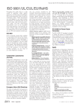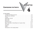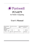
1
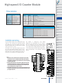
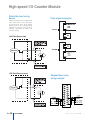
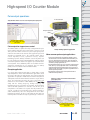
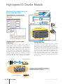
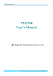
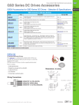
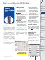
High-speed Counter I/O Module
PLC
Overview
DL05/06
PLC
CTRIO features
High-Speed
Counter I/O Module
H4-CTRIO
The CTRIO modules offer the following
I/O features:
• 8 DC sink/source inputs, 9-30 VDC
• 4 isolated sink/source DC outputs,
5-30 VDC, 1A per point
Inputs supported:
• 2 quadrature encoders counters up to
100 kHz, or 4 single channel counters up
to 100 kHz using module terminals Ch1A,
Ch1B, Ch2A and Ch2B
• High-speed edge timers, dual edge
timers, pulse catch, count reset, count
inhibit count capture or home search
limits using module terminals Ch1C,
Ch1D, Ch2C or Ch2D
Overview
The High-Speed Counter I/O (H4-CTRIO)
module is designed to accept high-speed
pulse-type input signals for counting or
timing applications and designed to provide
high-speed pulse-type output signals for
stepper/servo motor control, monitoring,
alarm or other discrete control functions.
The H4-CTRIO module offers great flexibility for applications that call for precise
counting or timing, based on an input event
or for high-speed control output applications.The H4-CTRIO module has its own
microprocessor and operates asynchronously with respect to the PLC/Controller.
This means that on-board outputs respond
in real time to incoming signals so there is
no delay waiting for the PLC/Controller to
scan I/O.
Outputs supported:
• 4 independently configurable highspeed discrete outputs or 2 channels
pulse output control (20 Hz-25 kHz per
channel)
• Pulse and direction or cw/ccw pulses
supported for pulse output control
• Raw control of discrete outputs directly
from the user control program
Software Configuration
All scaling and configuration is done via
CTRIO Workbench, a Windows software
utility program. This eliminates the need
for ladder programming to set up the
module. CTRIO Workbench runs under
Windows 98/2000/XP and NT 4.0 SP5
or later.
Typical applications
• High-speed cut-to-length operations
using encoder input
• Pick-and-place or indexing functions
controlling a stepper/servo drive
• Dynamic registration for web material
control
• Accurate frequency counting for speed
control with onboard scaling
• PLS (Programmable Limit Switch) functions for high-speed packaging, gluing,
or labeling
• Less than10 µ sec pulse-catch capability
for high-speed product detection
• Functions for level or flow
Supported systems
Multiple H4-CTRIO modules can reside
in the same base provided that the backplane power budget is adequate.
DirectLOGIC DL405 PLC
You can use the H4-CTRIO module with
the D4-450 CPU only. The D4-430 and
D4-440 CPUs do not support the CTRIO
module. The module plugs into any I/O
slot of any DirectLOGIC 405 base. The
CTRIO cannot be used in local expansion bases or in serial remote I/O bases.
PC-based Ethernet I/O
control systems
The H4-CTRIO module can be used in
PC-based control systems using the
H4-EBC interface module. H4-EBCs
support the use of the H4-CTRIO in
DL405 local expansion bases.
ERM to EBC systems
CTRIO Workbench main configuration screen
The H4-CTRIO module is designed to work
with incremental encoders or other field
devices that send pulse outputs.
DL105
PLC
DL205
PLC
DL305
PLC
DL405
PLC
Field I/O
Software
C-more
HMIs
Other HMI
AC Drives
Motors
Steppers/
Servos
Motor
Controls
Proximity
Sensors
Photo
Sensors
Limit
Switches
Encoders
Current
Sensors
Pushbuttons/
Lights
Process
The H4-CTRIO module is supported in
the H4-EBC slaves in H*-ERM systems.
Relays/
Timers
Comm.
TB’s &
Wiring
Power
Circuit
Protection
Enclosures
Appendix
Use Configure I/O dialog to assign
the CTRIO input and output functions
Part Index
w w w. l a m o n d e . c o m
PLC Products
6–47
High-speed I/O Counter Module
I/O Specifications
General Specifications
Module Type
Modules Per Base
I/O Points Used
Field Wiring Connector
Intelligent
Internal Power Consumption
400mA Max at +5V from Base Power Supply, Maximum of 6 Watts
(All I/O in ON State at Max Voltage/Current)
Operating Environment
Manufacturer
Isolation
32°F to 140°F (0°C to 60°C), Humidity (non-condensing) 5% to 95%
Limited only by power consumption
None, I/O map directly in PLC V-memory or PC control access
Standard removable terminal block
Host Automation Products, L.L.C.
2500V I/O to Logic, 1000V among Input Channels and All Outputs
H4-CTRIO Output Specifications
H4-CTRIO Input Specifications
Inputs
Minimum Pulse
Width
Input Voltage Range
Maximum Voltage
Input Voltage
Protection
Rated Input Current
Minimum ON
Voltage
Maximum OFF
Voltage
Minimum ON
Current
Maximum OFF
Current
OFF to ON Response
ON to OFF Response
8 pts sink/source
Outputs
4 pts, independently isolated, current sourcing or sinking
FET Outputs: open drain and source with floating gate drive
5 µsec
Voltage Range
Maximum Voltage
Output clamp Voltage
Maximum load Current
Maximum load Voltage
Maximum Leakage
Current
Inrush Current
OFF to ON Response
ON to OFF Response
ON State V Drop
External Power Supply
Overcurrent Protection
Thermal Shutdown
Overtemperature Reset
Duty Cycle Range
Configurable Presets
a) Single
b) Multiple
5VDC - 36VDC
36VDC
60VDC
1.0A
36VDC
9-30VDC
30VDC
Zener Clamped at 33VDC
8mA typical 12mA maximum
9.0VDC
2.0VDC
5.0mA (9VDC required to
guarantee ON state)
2.0mA
Less than 3 µsec
Less than 3 µsec
100µA
5A for 20ms
less than 3µsec
less than 3µsec
m 0.3V
for loop power only, not required for internal module function*
15A max
Tjunction = 150°C
Tjunction = 130°C
1% to 99% in 1% increments (default = 50%)
a) each output can be assigned one preset, or
b) each output can be assigned one table of presets, one table can contain max. 128 presets, max. predefined tables = 255
* User supplied power source required for stepper drive configuration.
H4-CTRIO Output Resources
H4-CTRIO Input Resources
4, (2 per 4 input channel group)
Counter/Timer up to 100KHz
Resource
Options
1X, 2X, or 4X Quadrature, Up or
Down Counter, Edge Timer, Dual
Edge Timer, Input Pulse Catch, Reset,
Inhibit, Capture
Pulse Output /
Discrete Outputs
Pulse outputs: 2 channels (2 outputs each channel) (20Hz-20KHz);
Discrete outputs: 4 pts.
Resource Options
Pulse outputs: pulse/direction or cw/ccw; Profiles:Trapezoid, S-Curve,
Symmetrical S-Curve, Dynamic Position, Dynamic Velocity, Home Search,
Velocity Mode, Run to Limit Mode and Run to Position Mode
Discrete outputs: 4 configurable for set, reset, pulse on, pulse off, toggle,
reset count functions (assigned to respond to Timer/Counter input functions).
Raw mode: Direct access to discrete output from user application program
Target Position Range
+ / - 2.1 billion (32 bits or 31 bits + sign bit)
Timer Range / 4.2 billion (32 bits); 1 µsec
Resolution
2.1 billion
Counter Range +(32/ -bits
or 31 bits + sign bit)
6–48
PLC Products
01737-824600
High-speed I/O Counter Module
PLC
Overview
DL05/06
PLC
DL105
PLC
Status indicators
DL205
PLC
H4-CTRIO LED Descriptions
OK
ER
1A - 1D
2A - 2D
(Ch1) F1 - F2
(Ch2) F1 - F2
Y0 - Y3
Module OK
H4-CTRIO LED Diagnostic Definitions
LED OK
User Program Error
LED ER
DL305
PLC
Description
ON
OFF
Ch1A - Ch1D Input Status
Blinking
Blinking
Ch2A - Ch2D Input Status
All is well - RUN Mode
Blinking
OFF
Ch1 Resource State
OFF
Blinking
Ch1 Resource State
OFF
ON
Module Error Due to Watchdog Timeout
Output Status
OFF
OFF
No Power to Module
TB
DL405
PLC
Boot Mode - Used for Field OS Upgrades
Program Mode
Field I/O
Module Self-diagnostic Failure
Software
User Terminal Block is not Properly Installed
C-more
HMIs
H4-CTRIO LED Diagnostic Definitions
1A - 1D
2A - 2D
(Ch1) F1
(Ch1) F2
(Ch2) F1
(Ch2) F2
Y0 - Y3
Other HMI
Follow actual input state / Ch1
Follow actual input state / Ch2
AC Drives
blinks when Channel 1 Function 1 is counting or timing
blinks when Channel 1 Function 2 is counting or timing
Motors
blinks when Channel 2 Function 1 is counting or timing
blinks when Channel 2 Function 2 is counting or timing
Steppers/
Servos
Follow actual output state; ON = output is passing current
Motor
Controls
Installation and wiring
Proximity
Sensors
The H4-CTRIO module has two independent input
channels, each consisting of 4 optically isolated
input points (pts. 1A-1D on common 1M and pts.
2A-2D on common 2M). The inputs can be wired to
either sink or source current.
The module is configured, using CTRIO
Workbench, to accommodate the user’s application. The function of each input (counting, timing,
reset, etc.) and output (pulse output, discrete output,
etc.) is defined in the configuration of the module.
The module has 4 optically isolated output points
(pts. Y0-Y3 with isolated commons C0-C3, respectively). The outputs must be wired so positive current
flows into the Cn terminal and then out of the Yn
terminal (see the diagram on the following page).
See the notes below for further details about power
source considerations, circuit polarities, and field
devices.
Photo
Sensors
Limit
Switches
Encoders
Current
Sensors
Pushbuttons/
Lights
Process
Notes:
1. Inputs (1A, 1B, 1C, 1D and 2A, 2B, 2C, 2D) require user-provided
9-30 VDC power sources. Terminals 1M and 2M are the commons
for Channel 1 and Channel 2 inputs. Maximum current consumption
is 12mA per input point.
Relays/
Timers
Comm.
2. Polarity of the input power sources (shown right) can be reversed.
Consideration must be given, however, to the polarity of the field
device. Many field devices are designed for only one polarity and
can be damaged if power wiring is reversed.
TB’s &
Wiring
3. Outputs have one polarity only (as shown) and are powered by user
provided 5-36 VDC power sources. The maximum allowable current
per output circuit is 1A.
Circuit
Protection
Power
Enclosures
Appendix
Part Index
w w w. l a m o n d e . c o m
PLC Products
6–49
High-speed I/O Counter Module
Solid state input wiring
device
Pulse output schematic
DC types of field devices are configured to
either sink or source current. This affects
the wiring of the device to the CTRIO
module. Refer to the sinking/sourcing
appendix in this desk reference for a
complete explanation of sinking and
sourcing concepts.
NPN Field Device (sink)
PNP Field Device (source)
Stepper/Servo drive
wiring example
6–50
PLC Products
01737-824600
High-speed I/O Counter Module
PLC
Overview
DL05/06
PLC
Fill-in-the-blank
configuration software
The CTRIO Workbench is the software utility used to configure the CTRIO
module and to scale signals to desired engineering units. Workbench also
allows you to perform various other functions, such as switching between
the CTRIO’s Program mode and Run mode, monitoring I/O status and
functions, and diagnostic control of module functions. The CTRIO
Workbench utility ships with the CTRIO User Manual. You can also download the latest version free at the Host Engineering’s Web site:
www.hosteng.com.
CTRIO Workbench configure I/O setup
The Configure I/O dialog is the location where input and
output functions are assigned to the module. The choice of
input and output functions determines which options are
available. The input function boxes prompt you with
selections for supported functions. The Workbench software
automatically disallows any unsupported configurations.
DL105
PLC
DL205
PLC
DL305
PLC
DL405
PLC
Configure I/O Screen
Field I/O
Software
CTRIO Workbench main configuration screen
C-more
HMIs
Other HMI
Select modules from multiple
networked PLCs
AC Drives
Save and load configurations
with Read/Write File feature
Motors
Steppers/
Servos
Motor
Controls
Proximity
Sensors
Detailed snap-shot of module
status and configurations
CTRIO Workbench diagnostics and monitoring
The Monitor I/O dialog is accessible from the main Workbench dialog
when the module is in Run Mode. This allows for a convenient way to test
and debug your configuration prior to installation. The Monitor I/O dialog
is divided into three functional areas: Input Functions, Output Functions and
System Functions. The data displayed under the Input Functions tab includes
all input Dword parameters, status bits and the current status of each
configured input and output function. The fields displayed under the Output
Functions tab includes all output Dword parameters and configuration
information that can be altered during runtime and the bits that indicate
successful transfers or errors. The System Functions can be used to read from
or write to the CTRIO’s internal registers.
Photo
Sensors
CTRIO Workbench on-board scaling
Scaling raw signals to engineering units is accomplished
using the Scaling Wizard. The Scaling Wizard options are
different for the Counter functions as compared with the
Timer functions. “Position” and “Rate” scaling are
available when you select a Counter function. “Interval”
scaling is available when you select a Timing function.
Limit
Switches
Encoders
Current
Sensors
Pushbuttons/
Lights
Scaling Wizard screen
Process
Relays/
Timers
Comm.
Monitor I/O screen
TB’s &
Wiring
Power
Monitor I/O dialog included
for easy de-bug features
Circuit
Protection
Enclosures
Appendix
Part Index
w w w. l a m o n d e . c o m
PLC Products
6–51
High-speed I/O Counter Module
High-speed input operations
The CTRIO module is capable of a wide variety of high
speed input and output operations all within one
module. With its flexible 2-channel input and separate
2-channel output design, the CTRIO can satisfy both
high-speed counting, timing, pulse catch operations,
along with high speed discrete output or several profile
choices of pulse output operations. Not all combinations of input functions and output functions are
possible within the resources of the module, but the
following examples are some of the most common
applications for the CTRIO. Check out these examples
and see how they relate to your high-speed application
needs.
High-speed counting
The CTRIO can be configured for counting functions for the
use of an encoder input, (up to two quadrature encoders per
module) with available connections for external reset and
inhibit signals. In a simple cut to length application as shown,
the encoder provides an input position reference for the material to the module. The module's high-speed outputs are wired
to the cutting device and to the clutch and/or braking device.
When the count from the encoder is equal to a preprogrammed setpoint within the module, the high speed
outputs are activated to stop and cut the material to a repeatable fixed length. Additionally, the clutch/brake signal can be
used for an inhibit signal to not accumulate counts while the
material is being cut.
High-speed cut-to-length application
High-speed timing
The CTRIO can be configured for timing functions
based on both count or rate. Using a common configuration of a proximity switch sensing the teeth on a
gear, the module is able to calculate the velocity of the
gear based on the rate it receives its counts. This value
can be scaled within the module to the engineering
units required for the application.
PLC with CTRIO module
Motor
Interface
Motor
control
lines
Gearbox, clutch and
brake interface
CTRIO high
speed output
High-speed timing application
PLC with CTRIO module
Encoder
Material to be
cut to length
Gear
Cutter interface
Cutter assembly
Proximity switch
Photoelectric switch
Using Configure I/O screen to configure
CTRIO for high-speed counting
High-speed edge timing application
Using Configure I/O screen to configure CTRIO for high-speed timing
Point-click selections of
hardwired connection for Counting,
Reset, and Inhibit
Powerful edge timing functions clicking on the edge button cycles through the
available edge timing functions available
6–52
PLC Products
01737-824600
High-speed I/O Counter Module
PLC
Overview
DL05/06
PLC
DL105
PLC
Pulse output operations
DL205
PLC
PLC with CTRIO module
Using Edit Pulse Profile screen to select Trapezoid pulse output profile
DL305
PLC
DL405
PLC
Fill spout
Field I/O
CTRIO pulse output signals
Software
C-more
HMIs
Stepper or
servo drive
Fill-in-the-blank parameters
allow precise tuning of the output
pulse profile
Pulse output for stepper/servo control
The CTRIO module is capable of multiple configurations for pulse
output control, most often when connected to a stepper or servo
drive system. The module can deliver a pulse output signal up to a
maximum of 25 kHz on two channels with support for pulse-anddirection or CW/CCW pulses. The available profile choices
include Trapezoid, S-Curve, Symmetrical S-Curve, Dynamic
Positioning, Dynamic Velocity and Home Search. All profiles can
be easily configured using the CTRIO Workbench software with fillin-the-blank parameter fields and a graphic representation of the
selected profile. Three additional profiles are available which are
completely controlled by the user program. They are Velocity
Mode, Run to Limit Mode and Run to Position Mode.
Example application
In a simple rotary indexing application, as shown above, a fixed
Trapezoid profile is chosen. The CTRIO for this application is wired
to a stepper drive for pulse-and-direction. The requirement for this
application is to provide a smooth movement of the rotary table to
allow product to be filled into individual containers equal distance
apart. The predetermined number of pulses required for each
movement is entered into the CTRIO Workbench as Total Pulses
along with the Starting Frequency, Ending Frequency, and
Positioning Frequency (speed after acceleration). The Acceleration
and Deceleration parameters are entered in units of time, so no
ramp-distance calculations are required. After all parameters are
entered, a graphical representation of the configured profile is
shown automatically. Once the configuration has been downloaded to the module, all that is needed from the PLC CPU is to
load the profile and enable the output signal to begin a movement.
Other HMI
Stepper
motor
Stepper motor
inside housing
Circular turn table
AC Drives
Motors
Rotary indexing liquid fill application
Other common pulse output applications:
• S-Curve accel/decel profile for signaling a stepper or servo
drive that needs a curved acceleration and deceleration profile, i.e. for diminishing any initial “jerk” upon movement of
static products, boxes on conveyors, liquids in containers on
an indexer, printing registrations, etc.
• Dynamic Positioning for any run-to-a-specific-position requirement, either by a pre-programmed count or an external high
speed discrete input wired to the module. This is popular in
winding or web control with any dynamic registration mark or
variable speed requirement.
• Home Search routines to seek a home position based on
CTRIO discrete input limit(s).
Steppers/
Servos
Motor
Controls
Proximity
Sensors
Photo
Sensors
Limit
Switches
Encoders
Current
Sensors
Pushbuttons/
Lights
Example of S-Curve acceleration and deceleration
pulse output profile
Process
Relays/
Timers
Comm.
TB’s &
Wiring
Power
Circuit
Protection
Enclosures
Calculate Profile displays
graphical representation of output
pulse profile
Appendix
Part Index
w w w. l a m o n d e . c o m
PLC Products
6–53
High-speed I/O Counter Module
Multihead drill machine application
Combining high-speed input and
pulse output operations
Using CTRIO Workbench to configure the module for
simultaneous high-speed input and high-speed pulse
output operation
Proximity switch
Proximity switch
Proximity switch
Encoder
Stepper motor
PLC with CTRIO module
Stepper or
servo drive
High-Speed inputs and pulse output
combinations
Example application
The flexible design of the CTRIO module allows for
combining high-speed inputs and delivering high-speed pulse
outputs signals simultaneously. There are limitations to this
type of configuration in that the module does not internally
support closed loop control. Providing closed loop control
with the CTRIO involves additional PLC code to coordinate
this control, making the application subject to the PLC CPU
program scan. Simple position/speed monitoring via a highspeed counting input for non-critical response while providing
pulse outputs to a drive is easily achievable for the CTRIO.
PLC CPU program
In the simple drill-head application shown above, the CTRIO
pulse outputs are wired to a stepper and/or servo drive. The
inputs are wired to an encoder attached to the lead screw on
the movable portion of the drill-head assembly. The CTRIO
module output pulse train to the drive allows the motor to spin
the lead screw making the drill move forward into the passing
material. The encoder monitors the speed and position of the
drill-head. Prox switches at each end act as limit switches
ensuring the drill-head will not over-travel. A home sensor is
positioned in the middle of the assembly which allows the PLC
to reset the count.
CTRIO pulse output profile
Closed loop control for the CTRIO module requires PLC
CPU program interaction to close the loop. This makes the
application subject to the PLC CPU scan.
CTRIO high-speed input pulse train
6–54
PLC Products
01737-824600