1
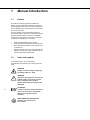
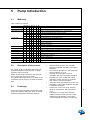
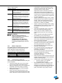
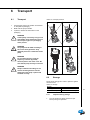
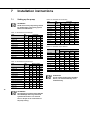
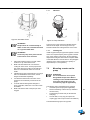
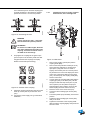
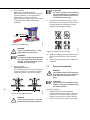
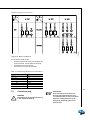
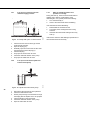
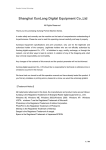
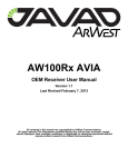
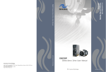
Vertical multi-stage centrifugal pumps
Installation and operating instructions
series: DPV and DPLHS
Table of Contents
1
Manual Introduction
1.1
1.2
2
Identification, service and technical support
2.1
2.2
2.3
2.4
2.5
3
8
Setting up the pump............................................................................................................................. 18
Mounting a motor on the pump ............................................................................................................ 19
Electrical installation ............................................................................................................................ 22
Commissioning .................................................................................................................................... 23
Operation
8.1
9
Transport.............................................................................................................................................. 17
Storage................................................................................................................................................. 17
Installation instructions
7.1
7.2
7.3
7.4
2
Model key..............................................................................................................................................11
Description of the product .....................................................................................................................11
Ecodesign .............................................................................................................................................11
Intended use ........................................................................................................................................ 12
Operation ............................................................................................................................................. 12
Measuring, draining and venting.......................................................................................................... 13
Modular selection................................................................................................................................. 13
Working range...................................................................................................................................... 13
Explosion safety................................................................................................................................... 14
Transport
6.1
6.2
7
General .................................................................................................................................................. 9
Users...................................................................................................................................................... 9
Safety provisions.................................................................................................................................... 9
Safety precautions ................................................................................................................................. 9
Environmental aspects......................................................................................................................... 10
Pump Introduction
5.1
5.2
5.3
5.4
5.5
5.6
5.7
5.8
5.9
6
Terms of warranty .................................................................................................................................. 8
Safety and environment
4.1
4.2
4.3
4.4
4.5
5
Obtaining data and information DPV 2, 4, 6, 10, 15, 25, 40, 60, 85....................................................... 5
Obtaining data and information DPV 45, 65 & DPLHS 6 ....................................................................... 6
Seal codes ............................................................................................................................................. 7
Current ................................................................................................................................................... 7
Supplementary documentation .............................................................................................................. 7
Warranty
3.1
4
Preface................................................................................................................................................... 4
Icons and symbols ................................................................................................................................. 4
Operation ............................................................................................................................................. 25
Maintenance
9.1
9.2
9.3
Introduction .......................................................................................................................................... 26
Lubrication ........................................................................................................................................... 26
Maintaining the pump for an extended period of non-operation .......................................................... 26
10 Failures
10.1 Failure table ......................................................................................................................................... 27
10.2 Torques of coupling shell - pos 914.01 ................................................................................................ 29
11 Annexes
11.1 EC declaration of conformity................................................................................................................ 30
3
1
Manual Introduction
1.1
Preface
This manual contains important information for
reliable, proper and efficient operation. Compliance
with the operating instructions is of vital importance to
ensure reliability and a long service life of the product
and to avoid any risks.
The first chapters contain information about this
manual and safety in general. The following chapters
provide information about normal use, installation,
maintenance and repairs of the product. The annex
contains the declaration(s) of conformity.
•
•
•
•
1.2
Make yourself familiar with the content.
Accurately follow the directions and instructions.
Never change the sequence of the operations to
be carried out.
Keep this manual or a copy of it together with the
logbook in a fixed place near the product which
can be accessed by all personnel.
Icons and symbols
In this manual and in all accompanying
documentation the following icons and symbols are
used.
WARNING
Danger of electric Voltage. Safety sign
according to IEC 417 - 5036
WARNING
Operations or procedures, if carried out
without caution, may cause personal
injury or damage to the product.
General hazard sign according to ISO
7000-0434
4
ATTENTION
Is used to introduce safety instructions
whose non-observance may lead to
damage to the product and its
functions.
ENVIRONMENTAL INSTRUCTION
Remarks with respect to the
environment.
2
Identification, service and technical
support
2.1
Obtaining data and
information DPV 2, 4, 6, 10,
15, 25, 40, 60, 85
The name plate indicates the type series / size, main
operating data and identification number. Please
quote this information in all queries, repeat orders
and particularly when ordering spare parts. If you
need any additional information or instructions
exceeding the scope of this manual or in case of
damage, please contact DP-Pumps nearest customer
service centre.
Figure 2: Pump without factory mounted
motor
3481
ID3481
H
Figure 3: Duty point
3060
Figure 1: Pump with motor
3297
ID3297
Table 1: Description nameplate
Indication
Meaning
DPVCF 85/2-1 B
Model key (design version B)
15 kW (12.5 kW)
Installed motor power (required power @ max. curve)1 2
Frame 160
Motor frame size
50 Hz
Nominal frequency
ID
29083352019B
Pump ID > as built file
Q3
72 m3/h
Optimum capacity running at fixed speed (see fig.: 3 Duty point)
H
42.1 m
Optimum head running at fixed speed (see fig.: 3 Duty point)
Eff.
74% (MEI>=0.60)
Minimum Efficiency Index
n fix.
2950 rpm
Rotation speed indication at which Q/H are given
PO
600097191
Production order number
Prod.
WW / YYYY XXXXXXX-XXXX
Production week/year and production serial number
Seal.
Ca/Sic
Mechanical Seal Surface Code, see fig.: 2.3 Seal codes
EPDM
Pump Elastomers
PN10 -20/+100°C
Maximum pressure at mentioned temperature4
Easy access
Seal construction type
Hydr.
PN40+80°C/140°C+PN25
Maximum temperature at mentioned pressure
Conn.
PN16
Pressure Class connection
1.
For pumps without a factory mounted motor: Frame size.
2.
When the Installed motor power is less than the required power, the pump is limited in it's operating range. Consult your
3.
Optimum capacity of the hydraulics, restricted operating range (note 1.) not taken into account.
4.
At lower pressure, a higher temperature is allowed (please consult your supplier).
sales representative for details.
5
Obtaining data and
information DPV 45, 65 &
DPLHS 6
ID 2517/13062005
The name plate indicates the type series / size, main
operating data and identification number. Please
quote this information in all queries, repeat orders
and particularly when ordering spare parts. If you
need any additional information or instructions
exceeding the scope of this manual or in case of
damage please contact DP-Pumps's nearest
customer service centre.
+120°C
2517/13062005
2.2
Pump without motor
H
2446/13062005
ID2446/13062005
+120°C
3060
Pump with motor
Figure 4: Duty point
Table 2: Description nameplate
Indication
Meaning
DPVF 45-10
Model key (number of stages x10)
4.0 kW(8.4A)1
Installed motor power (current)
(3.6kW)
Required motor power
50 Hz
ID
6
Nominal frequency
22450010
Article number
Q
39.6 m3/h
Optimum capacity running at fixed speed (see fig.: 4 Duty point)
H
18.4 m
Optimum head running at fixed speed (see fig.: 4 Duty point)
n fix
2850 rpm
Rotation speed indication at which Q/H are given
PO
600123456
Production order number
Prod
WW / YYYY XXXXXXX-XXXX
Production week/year and production serial number (As built file)
Seal
Ca/Sic
Mechanical Seal Surface Code, See: 2.3 Seal codes
EPDM
Pump Elastomers
Hydr.
PN25 +120°C
Maximum temperature at mentioned pressure2
Conn.
DIN/NW80
Connection size
MEI
>=0.10
Minimum Efficiency Index
1.
For pumps delivered with special motors no values are given (please use values as indicated on the motor type plate)
2.
General temp and pressure indication. Allowable pressures and temperatures also depend on type of sealing.
The following address data are available for service
and technical support:
DP-Pumps
service department
Kalkovenweg 13
2401 LJ Alphen a/d Rijn
The Netherlands
Tel: +31 172 488388
Fax: +31 172 468930
Internet: www.dp-pumps.com
E-mail: [email protected]
2.3
Seal codes
Table 3: Material code shaft seal
Code acc. to EN 12756
Description
Material
B
Q1
U3
Spring loaded ring
Carbon graphite
Silicon carbide
Tungsten carbide
Ca
SiC
TuC
Resin impregnated
Sintered pressureless
CrNiMo-binder
A
B
Q1
U3
Seat ring
Carbon graphite
Carbon graphite
Silicon carbide
Tungsten carbide
Ca
Ca
SiC
TuC
Antimony impregnated
Resin impregnated
Sintered pressureless
CrNiMo-binder
E
V
X4
Elastomers
EPDM
FPM
HNBR
EPDM
FPM
HNBR
Ethylene propylene rubber
Fluor carbon rubber
Hydrogenated nitrile rubber
G
Spring
CrNiMo steel
G
Other metal parts
CrNiMo steel
Information about seal combinations, types, pressure
and temperature see: table 9 Sealings
2.4
Note
On the pump plate (sleeve sticker) this "pump current
at 400 Volts" will be mentioned as I nom. and can be
used to pre-set the motor protection switch to protect
the pump/motor combination.
Current
ID 2446
Nominal current
DPV 2, 4, 6, 10, 15, 25, 40, 60, 85
The nominal allowable current of the motor is stated
on the motor plate. This shows the nominal working
range of the motor and can be used to protect the
motor.
Measuring the actual current of the pump during
operation can be used to pre-set the motor protection
switch to protect the pump/motor combination.
This current value can also be used to determine the
proper electrical equipment such as variable
frequency drive, main switch, wiring diameter etc.
WARNING
Not only the motor, but also the pump
has to be protected in its application.
+120°C
2446
2.4.1
This current value can also be used to determine the
proper electrical equipment such as variable
frequency drive, main switch, wiring diameter etc.
2.5
Supplementary
documentation
Apart from this manual, the documentation given
below is also available:
Table 4: Supplementary documentation
2.4.2
Maximum current
DPV 45, 65 & DPLHS 6
The maximum allowable current of the motor is
mentioned as I.max. on the motor plate. This
maximum allowable current shows the maximum
working range of the motor and can be used to
protect the motor.
WARNING
Be careful in using it this way, because,
not only the motor, but also the pump
has to be protected in its application.
Document
Code
General terms of delivery
119 / 1998
DPV 2, 4, 6, 10, 15, 25, 40, 60, 85
Technical Data 50 Hz Version B
97004455
Technical Data 60 Hz Version B
97004456
7
DPV 45, 65 & DPLHS 6
Technical Data 50Hz
97004434
Technical Data 60Hz
97004435
See also www.dp-pumps.com
3
Warranty
3.1
Terms of warranty
The warranty period is settled by the terms of your
contract or at least by the general terms and
conditions of sales.
ATTENTION
Modifications or alterations of the
product supplied are only permitted
after consultation with the
manufacturer. Original spare parts and
accessories authorized by the
manufacturer ensure safety. The use of
other parts can invalidate any liability of
the manufacturer for consequential
damage.
ATTENTION
The warranty relating to the operating
reliability and safety of the product
supplied is only valid if the product is
used in accordance with its designated
use as described in the following
sections of this manual. The limits
stated in the data sheet must not be
exceeded under any circumstances.
The warranty becomes invalid if one or more of the
points below occur.
• The buyer makes modifications himself.
• The buyer carries out repairs himself or has
these carried out by a third party.
• The product has been handled or maintained
improperly.
• The product has non original DP-Pumps spare
parts fitted.
DP-Pumps repairs defects under warranty when:
•
8
They are caused by flaws in the design, the
material or the production.
• They are reported within the warranty period.
Other terms of warranty have been included in the
general terms of delivery, which are available upon
request.
4
Safety and environment
4.1
General
This DP-Pumps product has been developed using
state-of-the-art technology; it is manufactured with
utmost care and subject to continuous quality control.
DP-Pumps does not accept any liability for damage
and injury caused by not observing the directions and
instructions in this manual, or in cases of
carelessness during the installation procedure, use
and maintenance of the product.
Non-compliance with safety instructions can
jeopardize the safety of personnel, the environment
and the product itself. Non-compliance with these
safety instructions will also lead to forfeiture of any
and all rights to claims for damages.
For example, in particular non-compliance can result
in:
•
•
•
•
•
failure of important pump/system functions,
failure of prescribed maintenance and servicing
practices,
injury to persons by electrical, mechanical and
chemical effects,
hazard of the environment due to leakage of
hazardous substances,
explosions.
Depending on specific activities, extra safety
measures may be required. Contact DP-Pumps if a
potential danger arises during use.
ATTENTION
The owner of the product is responsible
for compliance with the local safety
regulations and internal company
guidelines.
ATTENTION
Not only must the general safety
instructions laid down in this chapter
on "Safety" be complied with, but also
the safety instructions outlined under
specific headings.
4.2
Users
All personnel involved in the operation, maintenance,
inspection and installation of the product must be fully
qualified to carry out the work involved and be aware
of all applicable responsibilities, authorisations and
super visions. If the personnel in question is not
already in possession of the required know-how,
appropriate training and instruction must be provided.
If required, the operator may commission the
manufacturer / supplier to take care of such training.
In addition, the operator is responsible for ensuring
that the contents of the operating instructions are fully
understood by the responsible personnel.
4.3
Safety provisions
The product has been designed with the greatest
possible care. Original parts and accessories meet
the safety regulations. Modifications in the
construction or the use of non-original parts may lead
to a safety risk.
ATTENTION
Make sure that the product operates
within its working range. Only then the
product performance is guaranteed.
4.3.1
Labels on the product
The icons, warnings and instructions applied to the
product are part of the safety provisions. The labels
may not be removed or covered. Labels must remain
legible during the entire life of the product. Replace
damaged labels immediately.
4.4
Safety precautions
4.4.1
During normal use
• Contact the local electricity company for
questions about the power supply.
• Cover the parts that can become hot, making
direct contact impossible.
• When applicable, always place undeformed
coupling protection plates to protect the
coupling, before putting the pump into use. Make
sure that the coupling protection plates are
never in contact with the rotating coupling.
• Always close the terminal box of the motor.
9
4.4.2
During installation, maintenance and
repair
Only authorised personnel may install, maintain and
inspect the product and repair electrical components.
Observe the local safety regulations.
WARNING
Always disconnect the energy supply to
the product first, before installation,
maintenance and repairs. Secure this
disconnection.
WARNING
Surfaces of a pump can be hot after
continuous operation.
WARNING
Make sure that no one can be near
rotating components when starting a
pump.
WARNING
Handle a pump with dangerous liquids
with the utmost care. Avoid danger for
persons or the environment when
repairing leakages, draining liquids and
venting. It is strongly recommended to
place a leakage tray under the pump.
WARNING
Immediately following completion of
the work, all safety-relevant and
protective devices must be re-installed
and / or re-activated.
WARNING
Please observe all instructions set out
in the chapter "Commissioning/Startup" before returning the product to
service.
4.5
10
Environmental aspects
4.5.1
General
The products of DP-Pumps are designed to function
in an environmentally friendly way during their entire
life. Therefore, when applicable, always use
biodegradable lubricants for maintenance.
ENVIRONMENTAL INSTRUCTION
Always act according to the laws, bylaws regulations and instructions with
respect to health, safety and the
environment.
4.5.2
Dismantling
The owner is responsible for the dismantling and
environmentally friendly disposal of the product.
ENVIRONMENTAL INSTRUCTION
Ask at the local government about the
re-use or the environmentally friendly
processing of discarded materials.
5
Pump Introduction
5.1
Model key
Table 5: Model key Example
DP VS F 85 /3
Label
-1 B
DP
Material/Construction
Product Label
VC
Cast Iron pump foot and top bracket hydr. 1.4301 / AISI 304
V
All wetted parts Stainless Steel 1.4301 / AISI 304
VM
All wetted parts Stainless Steel 1.4301 / AISI 304 with closed coupled motor
VS
Connections
All wetted parts Stainless Steel 1.4401 / AISI 316
E
Male thread (with non-return valve insert)
Oval flange with female thread
F
Round flange
V
Victaulic connections
T
Tri-clamp connections
Size (Capacity in m3/h at Qopt)
85
/3
/3
Number of stages
-1
Number of stages of which one stage with reduced head
B Design version B
Size (Capacity in m3/h at Qopt)
45
-30
-30 -1
Number of stages (x10)
Number of stages (x10) of which one stage with reduced head
Design version
5.2
Description of the product
The vertical, single or multi stage centrifugal pump
series are designed for pumping clean, or slightly
aggressive, watery mediums.
Suction and discharge connections of the pump are
in-line, making the pump easy to install.
The hydraulic assembly is driven by an electric motor.
All hydraulic parts of the pump are made of stainless
steel.
5.3
Ecodesign
Product according to Regulation 547/2012 (for water
pumps with maximum shaft power rating of 150 kW)
to Directive 2009/125/EC "Ecodesign Directive":
•
•
•
•
•
•
•
Minimum Efficiency Index: See nameplate,
legend for nameplate. See table 1 Description
nameplate.
The reference value MEI of a water pump with
the best efficiency is = 0.70.
Year built: See nameplate, legend for
nameplate. See table1 Description nameplate.
Manufacturer's name or trademark, official
registration number and place of production:
See manual or order documentation.
Information about type and size of the item: See
nameplate, Legend of the nameplate. See table
1 Description nameplate.
Performance curves of the pump, including
efficiency characteristics: See documented
curve.
The efficiency of a pump with a corrected
impeller is usually lower than that of a pump
impeller with a full diameter. A pump with a
corrected impeller is adapted to a certain duty
11
•
•
5.4
5.5
Operation
ID3027
Intended use
The pumps DPV are suitable to transport and
increase the pressure of cold and hot water without
wear to parts within the indicated working range. The
transport of liquids with a different viscosity or density
than water is possible as well. For this a motor with an
adjusted power could be required. Ask DP-Pumps or
your distributor for advice.
Any other or further use of the pump is not in
conformity with its intended use. DP-Pumps does not
accept any liability for any damage or injury that
results from this. The pump is produced in
accordance with the current standards and
guidelines. Use the pump only in a perfect technical
state, in conformance with the intended use
described below.
G
B
12
C
A
D
E
The Intended use as laid down in ISO 12100:2010 is
the use for which the technical product is intended
according to the specifications of the manufacturer.
The use of the product has been described in the
sales brochure and in the user manual. Always
observe the instructions given in the user manual.
When in doubt the product must be used as becomes
evident from its construction, version and function.
G
Figure 5: DPVF 85
F
20080190-A/27022008
•
point, thereby reducing the energy consumption.
Minimum Efficiency Index (MEI) refers to the full
impeller diameter.
The operation of this water pump at different
operating points can be more efficient and more
economical when it is controlled, for example
using a variable speed controller which adjusts
the pump operation to the system.
Information for disassembly, recycling or
disposal after the final shutdown: See sub
chapter 4.5.2 Dismantling.
Information about the efficiency reference value
or MEI = 0.7 (0.4) benchmark index for the pump
on the basis of the pattern in the picture, please
visit: http://www.europump.org/efficiencycharts.
The rotating impeller causes the pressure at the inlet
of the impeller to drop. This decrease in pressure
creates the flow through the suction connection (A).
Every stage (B) consists of an impeller and a diffusor.
The capacity of the pump is determined by the size of
the passageway of the stage. The pressure of the
stage is determined by the diameter of the impeller.
Because of the modular type of construction it is
possible to choose the number of impellers most
suited to the required duty point. After leaving the last
impeller the medium flows between the pump stages
and the outer sleeve (C) and exits the pump at the
discharge connection (D)
5.6
Measuring, draining and
venting
Pump type
The pump is provided with plugs for measuring,
draining and venting.
Connection (E) is meant to drain the inlet part of the
pump, or to measure the inlet / suction pressure using
a G ¼ connection.
Connection (F) is meant to drain the outlet part of the
pump, or to measure the discharge pressure using a
G ¼ connection.
Connections (G) are meant to vent the pump system
when the pump is not in operation, or to measure the
discharge pressure of the pump using a G 3/8
connection.
DPV
note
Minimum frequency [Hz]
30
Maximum frequency [Hz]
60
4
Maximum number of starts
see motor data sheet
5
Noise emission
see motor data sheet
6
Allowable size of solids
pumped
5 µm to 1 mm
1.
Avoid freezing the pump.
2.
If the ambient temperature exceeds the above value or
the motor is located more than 1000 m above sea
level, the motor cooling is less effective and could
require an adapted motor power. Please contact your
supplier for more detailed advice.
3.
Deviation in viscosity and/or density could require an
adapted motor power. Please contact your supplier for
more detailed advice.
5.7
•
•
•
Basic pump model. Defines the capacity and
head, the basic material and allowable
pressures and temperatures.
Connections. Defines the connection size,
pressure class and allowable temperatures.
Sealings. Defines material of the elastomers,
shaft seal type and allowable pressures and
temperatures.
Electric motor. Defines all requirements of the
motor such as size, power, supply voltage,
frequency and possible motor accessories.
5.8
Working range
The working range depends on the basic hydraulic
design, the type of connection and sealings. The
module in the pump with the strictest specification
determines the allowable pressure and temperature
of the medium in the pump. The general working
specifications can be summarised as follows:
Table 6: General working range specification
Pump type
Ambient temperature [°C]
Minimum inlet pressure
Viscosity [cSt]
Density [kg/m3]
Cooling
DPV
-20 up to 40
NPSHreq. + 1 m
note
12
,
1-100
3
1000-2500
2
forced motor cooling
Pumps that are intended for 50 Hz operation, may not
5.
Frequent start/stops, in particular in combination with
be connected to 60 Hz power supply.
Modular selection
For a optimal match with the application, the pump is
assembled out of modules which are selected
depending on their specifications.
The basic modules are:
•
4.
higher pressure differences (Δp) may result in a shortened product lifetime. Consult your supplier for such
applications.
6.
Only the noise emission of the motor is documented.
ATTENTION
The temperature difference between the
medium and the pump should never
exceed 60 °C. The pump must be filled /
heated-up slowly in any case where the
difference between pump and medium
is more then 30 °C to avoid any chance
of a thermal shock.
For minimum/maximum flow at medium temperature
of 20 oC see table 7 Minimum/maximum capacity
(Qmin/max); for higher temperatures see figure 6
Minimum capacity vs. temperature (in % of Q
optimum)
Table 7: Minimum/maximum capacity (Qmin/max)
size
Qmin/max [m3/h]
50 Hz
60 Hz
2 pole
4 pole
2 pole
Min. Max. Min. Max Min. Max.
4 pole
Min. Max.
2
0.2
3.3
0.2
4.0
4
0.4
6.5
0.5
7.8
6
0.6
9.0
0.8
8.6
10
1.1
13.2
0.5
6.6
1.3
15.8
0.6
7.9
15
1.6
22.5
0.8
11.3 2.0
27.0
1.0
13.5
25
2.8
35.0
1.4
17.5 3.1
42.0
1.6
21.0
40
4
54
1.9
27
65
2.3
32.5
4.9
13
size
Qmin/max [m3/h]
1.
50 Hz
60 Hz
2 pole
4 pole
bled with different allowable conditions. If in doubt con-
2 pole
4 pole
Min. Max. Min. Max Min. Max.
45
4.6
57
60
5.3
57
65
6.1
75
85
8.5
110
LHS6 0.8
8.6
3675
40
2.6
38
4.3
5.1
65
6.4
92
6.1
90
sult your sales supplier.
Min. Max.
3.2
2.
LHS6 only
46
53.9 10.2 132.0 5.1
0.7
Next to the shaft seal other sealings might be assem-
5.9
65.1
Explosion safety
8.6
ATTENTION
This sub chapter contains fundamental
information which has to be taken in
consideration when installing the pump
with ATEX permission in a hazardous
environment.
Q [%]
35
30
25
20
15
10
5
0
40
50
60
70
80
90
100
110
120
130
140
Figure 6: Minimum capacity vs. temperature
(in % of Q optimum)
5.8.1
Detailed working range
DPV 2, 4, 6, 10, 15, 25, 40, 60, 85
For the actual working range of the pump see the
name plate.
3675
T [oC]
5.9.1
General
Stickers or indicators on the pump sleeve and the
motor indicate whether the pump is suitable for use in
an environment with risk of explosion.
It is allowed to install the pump in a zone which is
classified in directive 1999/92/EC.
When in doubt it is compulsory to check the above
directive.
5.9.2
Indication
ID2512
Detailed working range
DPV 45, 65 & DPLHS 6
Table 8: Basic hydraulic design
Pump type
Pressure [bar]
Temperature [°C]
25
120
DPV 45
DPV 65
25
DPLHS 6
40
Table 9: Sealings
14
Shaft seal materials1
type
pressure
[bar]
temperature [°C]
Sic/Ca/EPDM WRC
RMG-G606 25
Ca/SiC/EPDM
MG-G60
10
120
Ca/SiC/FPM
MG-G60
10
80
90
SiC/Ca/EPDM
RMG-G606 25
120
SiC/Ca/FPM
RMG-G606 25
80
TuC/TuC/HNBR
RMG-G606 25
120
TuC/TuC/FPM
RMG-G606 25
80
SiC/SiC/EPDM
MG-G606
10
90
SiC/SiC/FPM
MG-G606
10
80
TuC/Ca/EPDM
RMG-G606 25
120
TuC/Ca/FPM2
M37GN2
40
80
TuC/Ca/EPDM2
M37GN2
40
120
Figure 7: Indication sticker explosion
safety
2512
5.8.2
Table 10: ATEX marking
Indication Meaning
II
Product group for use above ground, with the
exception of mine working where there can be
danger of explosion due to mine gas and/or
flammable substances.
2
Category 2: Equipment in this category is
intended for use in areas in which explosive
atmospheres caused by mixtures of air and
gases, vapours or mists or by air/dusts mixtures are likely to occur.
3
Category 3: Equipment in this category is
intended for use in areas in which explosive
atmospheres caused by mixtures of air and
gases, vapours or mists or by air/dusts mixtures are likely to occur or, if they do occur,
are likely to do so only infrequently and for a
short period only.
G
Suitable for an environment that is explosive
due to gas, vapour or fumes; not suitable for
an environment that is explosive due to dust.
T4/T3
Temperature class:
T4 for maximum surface temperature 135 °C
T3 for maximum surface temperature 200 °C
ATTENTION
When the pump is placed in an
explosion hazardous environment no
pump should be opened or
disassembled on site. Due to the
probable creation of sparks during
loosening and tightening of nuts and
bolts.
•
•
•
•
•
•
•
•
5.9.3
Medium temperature
The applied ATEX motor determines the maximum
allowable temperature of the pumped liquid. See
table 11 Maximum medium temperatures
Table 11: Maximum medium temperatures
•
•
ATEX marking motor Allowable medium temperature
Exe
60 °C
EXd
100 °C
Exde
60 °C
5.9.4
Commissioning (check list)
It is compulsory to check these points prior putting the
pump in operation.
• Check if the ATEX-data on the motor and the
pump are in line with the specified category.
• When the categories of the motor and the pump
are different, the lowest category is leading.
• Make sure that the pump is protected against
damage from outside.
• Make sure that the liquid temperature never
exceeds the maximum allowed temperature (see
table 11 Maximum medium temperatures). Apply
•
•
•
a temperature monitoring and limiting system,
meeting the requirements of EN 13463-6, that
stops the pump at too high medium
temperatures. Please note that the maximum
temperature noted on the name plate of the
pump refers to the technical specification of the
mechanical part of the pump and does not match
with the maximum allowed medium temperature
for ATEX applications.
Apply a monitoring and limiting system, meeting
the requirements of EN 13463-6, to prevent dry
running. It has to check the presence of the
medium at the inlet of the pump and stop the
pump when no medium is available.
Apply a monitoring and limiting system, meeting
the requirements of EN 13463-6, to secure that
the maximum current of the motor is not
exceeded.
If the motor is suited with a PTC; connect the
PTC to a monitoring and limiting system.
Check if the motor cable is suitable for the
current drawn by the motor. See: motor type
plate.
Check if the pump is fully filled with the liquid
(de-aerated). Do not run the pump dry.
Check the rotational direction of the motor. The
motor has to run clockwise (seen from the non
driven side). This direction is indicated with an
arrow on the pump top bracket.
Do not apply higher pressures in the pump than
specified in the name plate as being allowed at
the working temperature of the medium.
Do not operate the pump at flows lower than
specified in ‘Working range’.
Do not operate the pump at flows higher then
specified in the performance curve (see the
technical documentation).
Do not operate the pumps with inlet pressures
lower than specified in the NPSHreq
requirements (NPSHreq + 1 m). See the
technical documentation.
Make sure that the maximum particle sizes in the
medium does not exceed the values specified in
chapter 5.8 Working range.
The pump has to be de-aerated again when:
• the pump is taken out of operation;
• air has gathered in the pump.
Wrong adjustment of the coupling can cause
interference of pump parts. Assembling and
adjusting of the coupling has to be performed by
a certified mechanic from the supplier of the
pump. This holds if only a pump or a thrust
15
•
•
•
•
•
•
•
•
•
•
bearing housing is supplied but also if for
another reason the pump coupling has to be
assembled or adjusted.
Make sure the coupling guard is assembled.
Wrong assembly of the coupling guard could
cause it to vibrate during operation of the pump
or cause interference of pump parts. If the
coupling guard has to be (re)assembled, this has
to be done by a certified mechanic from the
supplier of the pump.
Make sure that the pump and the motor shaft are
running smoothly without excessive noise (e.g.
no parts are running against each other).
Wrong assembling of the mechanical seal can
cause malfunction of the pump. Assembling of
the cartridge or easy access seal has to be done
by a certified mechanic from the supplier of the
pump. This holds when the mechanical seal is
replaced or for another reason a cartridge/easy
access seal has to be assembled.
Make sure that only media is pumped that is
compatible with the seals and elastomers that
are applied in the pump (see technical
documentation).
Electric installation of the pump motor has to be
done by a ATEX certified mechanic.
The pump has to be equipotent bonded with the
surrounding parts of the installation.
When a flammable medium is pumped, do not
pump this medium at a higher temperature than
the ignition temperature of the medium plus
25 °C.
Take care that if a formerly intensively used
pump has not been used for some time, at high
pressures leakage at the shroud can occur.
Do not pump mediums which can have chemical
reactions with each other.
If the pump is supplied without motor, it is compulsory
to also check the following additional points prior
putting the pump in operation:
16
•
•
•
•
•
•
Wrong adjustment of the coupling can cause
interference of pump parts. Assembling and
adjusting of the coupling has to be performed by
a certified mechanic from the supplier of the
pump.
Apply a motor that is ATEX certified for
equipment group IIG (non-mining and gas).
The determination of the ATEX specification of
the assembly and certification is the
responsibility of the owner of the pump/motor.
The most stringent specification of the separate
parts of the pump is applicable.
Apply a motor that has a special bearing which is
suited to support the high axial loads of the
pump shaft. If this is not the case, a thrust
bearing housing has to be applied.
Apply a motor with a nominal power which is
suited to drive the pump at the operating
frequency.
Apply a motor that has the proper frame size to
connect to the motor stool.
If a pump supplied with thrust bearing housing or a
solely supplied thrust bearing housing is supplied, it is
compulsory to also check the following additional
points prior to putting the pump in operation:
• Wrong adjustment of the axial play between the
thrust bearing housing shaft and the motor shaft
could cause too high impacts between these
shafts. Assembling of the electric motor with the
thrust bearing housing has to be done by a
certified mechanic from the supplier of the pump.
• When the thrust bearing housing has a grease
nipple, the thrust bearing can be lubricated.
Proper lubrication is important to prevent high
temperatures in the bearing. If the thrust bearing
housing has a grease nipple it is obligatory to
supply on a yearly basis some grease through
this nipple to the bearing.
• Do not install the pump horizontally or upsidedown.
6
Transport
6.1
Transport
2.
3.
ID3079
ID3080
ID3081
ID3082
Transport the pump in the position as indicated
on the pallet or packaging.
Make sure the pump is stable.
If present, observe the instructions on the
packaging.
WARNING
Lift the pump, if necessary using a hoist
and suitable slings. Attach the slings to
the transport lugs on the packaging,
where present.
WARNING
The pump must be lifted according to
the current hoist guidelines. Only
qualified personnel is allowed to lift the
pump.
WARNING
Do not lift the pump by using the
frequency converter (if placed),
electrical parts or the motor cover. Be
sure that the pump is always in balance.
20080196/20080197/20080192/2008195
1.
Table 12: Transport positions
WARNING
Pumps could tilt while lifting. Do not
remove the lifting devices from the
pump before the pump is placed and
mounted correctly.
6.2
Storage
Fill the pump with glycol in order to protect it against
the risk of frost.
Table 13: Storage
Storage
tambient [°C]
-10/+40
Max. rel. humidity
80% at 20°C not condensing
6.2.1
1.
Inspection during storage
Turn the shaft every three months and just
before putting into operation.
17
7
Installation instructions
7.1
Setting up the pump
Table 16: Allowable forces DPVCF
Type
ATTENTION
Avoid stress in the pump casing caused
by misalignment in the piping system.
Please see table below.
Table 14: Allowable forces DPV(S)F
Type
DN
[mm] Fx
Force [N]
Fy
Fz
ΣF
V(S)F 2 B
25
3300 -2400 1700 4420
V(S)F 4 B
25
3300 -2400 1700 4420
V(S)F 6 B
32
3300 -2400 1700 4420
V(S)F 10 B
40
4000 -3100 3100 5930
V(S)F 15 B
50
4000 -3100 3100 5930
V(S)F 25 B
65
3200 -3500 3500 5890
V(S)F 40 B PN16/25
80
4000 -1800 2000 4820
V(S)F 40 B PN40
80
3700 -3300 3700 6190
V(S)F 60 B PN16/25
100
4000 -1800 2000 4820
V(S)F 60 B PN40
100
3700 -3300 3700 6190
V(S)F 85 B
100
3500 -2500 1000 4420
DPLHS 6
32
8000 -2000 3200 8800
20090283-F
Table 15: Allowable torque DPV(S)F
Type
DN
[mm]
Moment [Nm]
Mx
My
Mz
ΣM
V(S)F 2 B
25
280
95
-210
360
V(S)F 4 B
25
280
95
-210
360
V(S)F 6 B
32
280
95
-210
360
V(S)F 10 B
40
440
180
-200
520
V(S)F 15 B
50
440
180
-200
520
V(S)F 25 B
65
1000
230
-400
1100
V(S)F 40 B PN16/25
80
400
200
-300
540
V(S)F 40 B PN40
80
975
240
-450
1100
V(S)F 60 B PN16/25
100
400
200
-300
540
V(S)F 60 B PN40
100
975
240
-450
1100
V(S)F 85 B
100
750
500
-625
1100
DPLHS 6
32
460
460
-500
800
20090283-F
18
ATTENTION
The application of pump series DPV(S)F
45 and DPV(S)F 65 is only allowed in
systems where there is no external
force or torque on the connections of
the pump casing.
DN
[mm]
Fx
Fy
Force [N]
Fz
ΣF
VCF 2 B
25
9400
-3200
3200
10430
VCF 4 B
25
9400
-3200
3200
10430
VCF 6 B
32
9400
-3200
3200
10430
VCF 10 B
40
8000
-2000
3200
8850
VCF 15 B
50
8000
-2000
3200
8850
VCF 25 B
65
5000
-2000
2500
5940
VCF 40 B
80
6000
-3000
3000
VCF 45
80
48000
-17000 31000
59600
VCF 60 B
100
6000
-3000
7350
VCF 65
100
60000
-21000 33000
71600
VCF 85 B
100
6200
-4100
8490
3000
4100
7350
20090283-F
Table 17: Allowable torque DPVCF
Type
DN
[mm] Mx
My
Moment [Nm]
Mz
ΣM
VCF 2 B
25
600
300
-360
760
VCF 4 B
25
600
300
-360
760
VCF 6 B
32
600
300
-360
760
VCF 10 B
40
460
460
-500
820
VCF 15 B
50
460
460
-500
820
VCF 25 B
65
1000
300
-300
1090
VCF 40 B
80
1800
1000
-1000
2290
VCF 45
80
2700
2700
-2300
4500
VCF 60 B
100
1800
1000
-1000
2290
VCF 65
100
3300
3600
-3000
5700
VCF 85 B
100
2000
1200
-1200
2620
20090283-F
ATTENTION
For the values mentioned in the tables
above, it is assumed that they occur
simultaneously.
7.1.1
Indicators
ID3064
ID3078
ATTENTION
Pumps which do not stand steady or
stable on their own, should be mounted
on a rigid and stable base.
ATTENTION
Locate the pump at the place with the
lowest risk for noise nuisance.
1.
2.
3.
4.
5.
6.
Place and install the pump on a level, stable
surface in a dry and frost-free room.
Make sure that sufficient air can reach the
cooling fan of the motor. For this purpose the
free space above the cooling fan should be at
least 1/4 of the diameter of the fan cover air
intake.
Install the pump with counter flanges. For pumps
with non-standardised connections, counter
flanges are delivered separately.
It is advised to install a shut off valve on the
supply and on the delivery connection of the
pump.
To avoid medium flowing back through the
pump, when idle, make sure a non-return valve
is installed.
Make sure that the inlet of the pump is never
clogged.
A
Figure 9: Pump indicators
20080201/26022008
Figure 8: Allowable forces
20090283-F
B
The arrow (A) on the pump foot indicates the flow
direction of the liquid. The arrow (B) on the top
bracket indicates the rotating direction of the motor.
7.1.2
Install bypass
Install a bypass if the pump operates against a closed
valve. The required capacity of the bypass is at least
10% of the optimum volume flow. At high operating
temperatures a higher volume flow is required. Refer
to the table "Minimum volume flows" in the paragraph
"Working range" and fig 6 Minimum capacity vs.
temperature (in % of Q optimum).
7.2
Mounting a motor on the
pump
ATTENTION
It is to be advised to use a special
designed DP-Pumps motor. Before
installing an other brand/standard IECnorm motor, DP-Pumps has to be
consulted to judge the applicability.
The following motor specifications are required:
• Increased power output (when applicable)
• Reinforced bearing at driven end (to withstand
the axial force)
• Fixed bearing at driven end (to minimize the
axial play)
• Smooth shaft, no key way (to improve the
coupling grip and to improve the motor balance)
The advised bearings per motor type are:
19
1.
Table 18: Minimum required motor Driven-end
bearing
2.
Bearing type
Power 1 phase
output 50 Hz
3 phase
50/60 Hz
[kW]
2 pole
0.25
4 pole
6202-2Z-C3
0.37
6202-2Z-C3
6203-2Z-C3
6202-2Z-C3
0.55
6202-2Z-C3
6203-2Z-C3
6202-2Z-C3
0.75
6204-2Z-C3
6204-2Z-C3
6202-2Z-C3
1.1
6204-2Z-C3
6204-2Z-C3
6205-2Z-C3
1.5
6305-2Z-C3
6305-2Z-C3
6205-2Z-C3
2.2
6305-2Z-C3
6305-2Z-C3
6206-2Z-C3
3
6306-2Z-C3
6206-2Z-C3
4
6306-2Z-C3
6208-2Z-C3
5.5
6308-2Z-C3
6208-2Z-C3
7.5
6308-2Z-C3
6208-2Z-C3
11
7309
15
7309
18.5
7309
22
7311
30
7312
37
7312
45
7313
3.
4.
5.
6.
Remove the coupling guards (681) and the
coupling shells (862).
Remove the seal protection bracket (89-11.03)
and its mounting material. For pumps with a
taper piece (722) (with motor of 5.5 kW or
higher), the two bolts (914.02 or 901.02) has to
be placed back to connect the taper piece to the
motor stool. Thoroughly clean the motor stool
(341), the shaft (210), the coupling shells (862)
and the motor shaft.
Loosely fasten the coupling shells (862) with the
coupling pin (560) on the shaft (210). Use the
hexagon socket head cap screw (914.01) and
the nut (920.01) for this. (When the pump is
equipped with a steel coupling, never use the
same coupling twice but order a new one).
Place the motor on the motor stool (341).
Tighten the lower bolts of the coupling shells
(862) in such way, that the coupling slightly
clamps around the motor shaft.
For pump series:
DPV 2, 4, 6, 10, 15, 25, 40, 60, 85
Use a sufficient tyre iron to lift the coupling (and
hydraulic assembly) 1.5 mm higher then the
lowest position. For easy and accurate
adjustment of the coupling contact your supplier
for the appropriate Toolkit For Adjustment
Hydraulics.
20101096-C
7.2.1
Install the motor on pumps, supplied
without motor, with a standard
mechanical seal.
Figure 11: fixed seal
20090559
ID3312/20090403
WARNING
Correct seal adjustment max. 1.5 mm
higher then the lowest position.
20
Figure 10: Without motor
20090321
ATTENTION
For motors of 11 kW or higher, block the
rotor when adjustments are made to the
coupling. This ensures that the rotor is
not lifted out of its bearings.
7.
For pump series:
DPV 45, 65 & DPLHS 6
Figure 12: Positioning the seal
7.2.2
Installing the motor on pumps, supplied
without motor, with a cartridge seal
20070376
Use a sufficient tyre iron to lift the coupling (and
hydraulic assembly) to the maximum upwards
position and lower it 1 mm from this position.
WARNING
Correct seal tension max. -1 mm lower
than the maximum upwards position!
8.
Fully tighten the couplings at the given torque
(see "Torques" in the annexes). Make sure that
the gaps between the couplings are equally
divided on both sides (see drawing).
Figure 14: With motor
1.
2.
Figure 13: Position of the coupling
9.
20030733
3.
Attach the coupling guards (681) with the socket
head cap screws (914.05) to the motor stool
(341).
10. Connect the power supply. see § 7.3 Electrical
installation.
4.
5.
6.
7.
8.
20090322
ATTENTION
For motors of 11 kW or higher, block the
rotor when adjustments are made to the
coupling. This ensures that the rotor is
not lifted out of its bearings.
Remove the coupling guards (681) and the
coupling shells (862).
Remove the seal protection bracket (89-11.03)
and its mounting material. For pumps with a
taper piece (722) (with motor of 5.5 kW or
higher), the two bolts (914.02 or 901.02) has to
be placed back to connect the taper piece to the
motor stool. Thoroughly clean the motor stool
(341), the shaft (210), the coupling shells (862)
and the motor shaft.
Loosely fasten the coupling shells (862) with the
coupling pin (560) on the shaft (210). Use the
hexagon socket head cap screw (914.01) and
the nut (920.01) for this. (When the pump is
equipped with a steel coupling, never use the
same coupling twice but order a new one).
Place the motor on the motor stool (341).
Loosen the three cartridge grub screws (904)
one turn.
Push the hydraulic pump assembly in the lowest
position.
Tighten the three cartridge grub screws (904)
firmly to the shaft.
Tighten the lower bolts of the coupling shells
(862) so that the coupling slightly clamps around
the motor shaft.
21
For pump series:
DPV 2, 4, 6, 10, 15, 25, 40, 60, 85
Use a sufficient tyre iron to lift the coupling (and
hydraulic assembly) 1.5 mm higher then the
lowest position. For easy and accurate
adjustment of the coupling contact your supplier
for the appropriate Toolkit For Adjustment
Hydraulics.
11. Fully tighten the couplings at the given torque
(see "Torques" in the annexes). Make sure that
the gaps between the couplings are equally
divided on both sides (see drawing).
WARNING
Correct seal adjustment max. 1.5 mm
higher then the lowest position.
Figure 17: Position of the coupling
ATTENTION
For motors of 11 kW or higher, block the
rotor when adjustments are made to the
coupling. This ensures that the rotor is
not lifted out of its bearings.
10. For pump series:
DPV 45, 65 & DPLHS 6
Use a sufficient tyre iron to lift the coupling (and
hydraulic assembly) to the maximum upwards
position and lower it 1 mm from this position.
20030733
Figure 15: Cartridge seal
ATTENTION
For motors of 11 kW or higher, block the
rotor when adjustments are made to the
coupling. This ensures that the rotor is
not lifted out of its bearings.
20091316
9.
12. Install the coupling guards (681) with the socket
head cap screws (914.05) to the motor stool
(341).
13. Connect the power supply. see § 7.3 Electrical
installation.
7.3
Electrical installation
WARNING
In accordance with the local regulations
only authorised personnel is allowed to
make electrical connections to the
motor.
22
Figure 16: Positioning the seal
20070376
ATTENTION
Connect the motor according to figure:
18 Motor connections and always check
the rotation direction.
WARNING
Correct seal tension max. -1 mm lower
than the maximum upwards position!
Electrical connections:
• Make sure that the motor specifications
correspond with the power supply to which the
pump motor is connected. Consult "Electrical
diagrams" for the correct connection diagram.
• Connect the motor using a motor safety switch.
Example may differ upon chosen motor
Figure 18: Motor connections
20130499-A
ID2482
PTC connection STM 140 EK:
• Standard motors 3 kW and up are equipped with
a PTC thermistor. Consult Table 19 Technical
specifications PTC STM 140 EK.
• Connect the PTC to a thermistor relay.
Table 19: Technical specifications PTC STM 140 EK
Value
tn [oC]
140
R20 °C [Ώ]
~ 20
Rtn-20 °C [Ώ]
~ 250
Rtn-5 °C [Ώ]
< 550
Rtn+5 °C [Ώ]
> 1330
Rtn+15 °C [Ώ]
> 4000
Un [VDC]
2.5 < U < 30
23
7.4
Commissioning
WARNING
The pump must be switched off when it
is not completely filled up.
ATTENTION
Seen from the top of the motor the
pump should rotate clockwise. See
7.1.1 Indicators (B). In case of a 3-phase
motor the rotating direction can be
changed by exchanging two of the
three phases.
7.4.1
7.4.3
After an extended period of nonoperation or storage
During first start-up, check the mechanical seals for
leakage due to seizure or dehydration of the
lubricating film. If so, please proceed as following:
1. Turn shaft manually or;
2. Check if the mechanical seal is still leaking.
In an open or closed circuit with
sufficient supply pressure
ID0239
C
If the mechanical seal is still leaking:
1. Disassemble the mechanical seal.
2. Thoroughly clean and degrease the running
surfaces.
3. Assemble the mechanical seal again and retry
start-up.
A
Figure 19: Pump with open or closed circuit
1.
2.
3.
4.
5.
6.
7.
ID239
B
Close the suction shut-off valve (A) and the
outlet shut-off valve (B).
Open the fill plug (C).
Gradually open the suction shut-off valve until
the liquid flows from the fill plug (C).
Close the fill plug.
Fully open the suction shut-off valve.
Check the rotational direction of the pump.
Fully open the outlet shut-off valve.
7.4.2
In an open circuit with a liquid level
lower than the pump
ID0241
B
Figure 20: Liquid level lower then pump
24
1.
2.
3.
4.
5.
6.
Remove the fill plug (B) from the top bracket.
Close the outlet shut-off valve.
Fill the pump housing to the maximum through
the fill plug with the liquid that is to be pumped.
Insert the fill plug in the top bracket.
Check the rotational direction of the pump.
Open the outlet shut-off valve.
ID241
A
If this doesn’t solve the shaft leakage, replacement of
the mechanical seal is necessary.
8
Operation
8.1
Operation
The pump is controlled externally and therefore does
not need any operation guidance.
25
9
Maintenance
9.1
Introduction
WARNING
Observe the general safety precautions
for installation, maintenance and repair.
Regular maintenance is necessary for the correct
operation of a pump. Please contact your supplier for
maintenance of the pump.
9.2
Lubrication
Standard motors, with a maximum power of 7.5 kW,
are provided with maintenance free sealed bearings.
Motors with lubricating nipples must be lubricated
after 2000 hours. If the pump works under extreme
conditions, such as high vibrations and temperatures,
the motors must be lubricated more often.
Use a lithium based -30 °C / 160 °C bearing lubricant
(about 15 grams).
When the pump is delivered without a motor and fitted
with an other brand or the standard motor is replaced
by an other brand than DP-Pumps, please consult the
maintenance instructions of the motor supplier.
ATTENTION
Also follow the instructions in § 7.2
Mounting a motor on the pump.
9.3
26
Maintaining the pump for an
extended period of nonoperation
Turn the shaft every three months1. This protects the
seals from seizure.
Protect the pump if there is a risk of frost. Proceed as
follows:
1.
period may vary per application or medium. Please
consult your sales representative for application
details.
1.
2.
3.
4.
Close all pump valves.
Drain each pump and/or the system.
Remove all plugs from the pump.
Open the shut-off and fill/air vent plug, if present.
10 Failures
10.1
Failure table
WARNING
Observe the general safety precautions
before installation, maintenance and
repair.
Problem
Leakage along the shaft.
Possible cause
Running surfaces of the
mechanical seal worn or
damaged.
New pump: seal stuck due
to assembly.
Mechanical seal mounted
incorrectly.
Elastomers affected by
medium.
Pressure too high.
Shaft worn.
Pump has been operating
without water.
Leakage along the shroud O-ring worn
at the top bracket or at the O-ring not resistant to the
pump foot.
medium to be pumped
Too much stress on the
pump foot; it becomes
oval.
Pump is vibrating or noisy. Coupling mounted incorrectly.
Faulty setting of the
hydraulic assembly.
There is no water in the
pump.
No supply of medium.
Bearings of pump and/or
motor worn.
Available NPSH too low
(cavitation).
Possible solution
Replace the mechanical
seal.
Checkpoints
Check the pump for dirt /
abrasive parts.
Open and close the outlet
shut-off valve quickly during operation.
Install the mechanical seal
correctly. Use water and
soap as a lubricant.
Use the right rubber compound for the mechanical
seal.
Use the right type of
mechanical seal.
Replace shaft and
mechanical seal.
Replace the mechanical
seal.
Replace the O-ring.
Replace O-ring by an Oring with better resistance
Decrease stress on piping.
Mount the pump foot
without stress.
Support the connections.
Install the coupling in parallel.
Adjust the assembly
according to the manual.
Fill and vent the pump.
Make sure there is sufficient supply. Check for
blockages in the supply
line.
Have the bearings
replaced by a certified
company.
Improve suction condition.
27
Problem
Possible cause
Pump is vibrating or noisy. Pump does not work in its
working range.
Malfunction.
Pump does not start.
28
Pump is standing on an
uneven surface.
Internal blockage in the
pump.
No voltage on the power
terminal.
Possible solution
Select another pump or
adjust the system to work
within its working range.
Level the surface.
Have the pump inspected
by a certified company.
Check the power supply.
Checkpoints
•
•
•
•
•
Circuit
Main switch
Fuses
Earth leakage switch
Check the motor safety
relay
Protective relay
Thermal motor safety
Reset the thermal motor- Check if the correct value
is set. Find the correct
switch triggered.
safety. Contact the supplier, if this problem occurs value (Inom) on the motor
more often.
type plate.
Tighten the connecting
The motor is running, but The coupling between
the pump does not work.
pump- and motor shaft is screws to the required
torque.
loose.
The pump shaft is broken. Contact the supplier.
Pump supplies insufficient Outlet and/or inlet shut-off Open both shut-off valves.
capacity and/or pressure. valve is closed.
There is air in the pump.
Vent the pump.
The suction pressure is
Increase the suction presinsufficient.
sure.
Pump rotates in the wrong Change over L1 and L2 of
direction.
the three phase supply.
The suction line has not
Vent the suction line.
been vented.
Air bubble in the suction
Install the suction line with
line.
pump end higher than the
other end.
Repair the leakage.
Pump sucks air because
of leakage in the suction
line.
Water flow too low. So air Make sure the flow
increases or use a smaller
bubbles clog up in the
pump.
pump.
The diameter of the sucIncrease the diameter of
tion line is too small.
the suction line.
Capacity of water meter in Increase the capacity of
the water meter.
the supply line is too
small.
Foot valve blocked.
Clean the foot valve.
The impeller, the diffuser
Clean the inside of the
or stage is blocked.
pump.
O-ring between impeller
Replace the O-rings.
and diffuser is gone.
O-ring not resistant to the Replace O-ring by an Omedium to be pumped.
ring with better resistance.
10.2
Torques of coupling shell pos 914.01
Material
Dimensions
Torques [Nm]
Steel
M6
16
Steel / Cast iron
M8
30
Aluminium
M8
22
Cast iron
M10
70
29
11 Annexes
11.1
EC declaration of conformity
DP-Industries bv
Kalkovenweg 13
2401 LJ Alphen aan den Rijn, The Netherlands
Tel: (+31)(0)-172-48 83 88
Hereby declares as manufacturer entirely on his own responsibility, that the products:
Vertical multi-stage centrifugal pumps, series: DPV and DPLHS
Serial number: 18/2012 1000000-0001 [...] 52/2016 9999999-9999
In case the pump is delivered without ATEX classification:
to which this declaration refers, is in accordance with the following standard: EN 809: 1998+A1:2009/AC:2010
according to the provisions of the harmonized standard for pumps and which implies the regulations of Machine
directive 2006/42/EC, EMC directive 2004/108/EC, Ecodesign Directive 2009/125/EC, Regulation 547/2012(for
water pumps with a maximum shaft power of 150kW) in the most recent form
In case the pump is delivered, ordered and marked with an ATEX classification:
to which this declaration refers, is in accordance with the following standard: EN 809: 1998+A1:2009/AC:2010
according to the provisions of the harmonized standard for pumps and which implies the regulations of Machine
directive 2006/42/EC, EMC directive 2004/108/EC, Ecodesign Directive 2009/125/EC, Regulation 547/2012(for
water pumps with a maximum shaft power of 150kW) in the most recent form. The pump also complies with the
ATEX directive for Equipment Group II Category 2 as filed under number: 11 ATEX D048 by PTB (identification no.:
0102) and is in accordance with the standard: EN 13463-1:2009-07
The pump is subject to this declaration of conformity as a stand alone product. Make sure the appliance or
installation in which the pump is built in, has got a declaration of compliance with the directives listed above, for its
complete assembly.
Alphen aan den Rijn
01/12/2012
30
Authorized representative
W. Ouwehand, technical director.
31
dp pumps
dp pumps
P.O. Box 28
2400 AA Alphen aan den Rijn
The Netherlands
t +31 172 48 83 88
f +31 172 46 89 30
[email protected]
www.dp-pumps.com
11/2013
BE00000377-F
Can be changed without prior notice
Original instructions