1
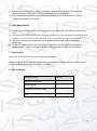
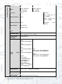
AMB-VANIR AMB-VANIR-2 AMB-VANIRM2 1.3 & 2 MEGA PIXEL VANDAL DOME IP CAMERAS User’s Manual V2.0 06 / 2014 i Welcome Thank you for purchasing the Vandal Dome IR LED IP Camera. This user’s manual is designed to be a reference tool for the installation and operation of your system. Here you can find information about the corresponding IP camera’s features and functions, as well as a detailed installation method. Before installation and operation please read the following safeguards and warnings carefully! ii Important Safeguards and Warnings 1.Electrical safety All installation and operation here should conform to your local electrical safety codes. The power supply shall conform to the requirement in the SELV (Safety Extra Low Voltage) and must make sure that the limited power source is rated 12V DC or 24V AC. Please note: Do not connect two power supplying sources to the device at the same time; it may result in device damage! We assume no liability or responsibility for all the fires or electrical shock caused by improper handling or installation. We are not liable for any problems caused by unauthorized modification or attempted repair. 2.Transportation Security Please ensure that the product does not endure heavy stresses, violent vibration or contact with water during transportation, storage and installation. Please use the original packing material (or the material of the same quality) if you need to return it to vendor. 3.Installation Do not apply power to the product before completing installation. Do not put object(s) on the product. Please install a proper power cut-off device during the installation connection. 4.Qualified engineers needed All the examination and repair work should be done by the qualified service engineers. We are not liable for any problems caused by unauthorised modifications or attempted repair. 5. Environment This product should be installed in a cool, dry place away from direct sunlight, inflammable, explosive substances and etc. Please keep it away from environments that contain electromagnetic radiation or objects that produce it. Please keep sound ventilation around the device at all times. Do not allow the water and other liquid to penetrate into the device if casing has been compromised. This series product complies with the IP66 standard specified in the Degrees of Protection Provided by Enclosure. Ensure lightning surge protection is in place to make sure you fully protect camera circuitry from electrical overload. iii Please make sure the CCD (CMOS) component is away from the radiation of the laser beam device. Otherwise it may result in CCD (CMOS) optical component damage. It is recommended that the grounding studs of the product should be grounded, so to further enhance the reliability of the camera. 6. Daily Maintenance Please shut down the device and then unplug the power cable before you begin any maintenance work. Do not touch the CCD (CMOS) optic component. Please use an air jet to clean the dust off the lens surface. You can use the dry cloth with some alcohol or mild detergent to clear if necessary. When the camera is not in use please put the dustproof cap to protect the CCD (CMOS) component. Do not use volatile solvent such as the benzene, paint thinner or detergent with the ability to abrade surfaces. It may result in lens damage or adversely affect the device’s performance. 7. Accessories Always use all the accessories recommended by manufacturer. Before installation, please open the package and check that all the components are included. Contact your local retailer/vendor ASAP if something is missing. 8. Box Contents: Accessory Name Amount Network Camera Unit 1 User’s Manual 1 Installation Accessories Bag 1 CD 1 iv Table of Contents 1 2 3 4 5 6 General Introduction ..................................................................................................... 1 1.1 Overview ........................................................................................................... 1 1.2 Features ............................................................................................................ 1 1.3 Specifications .................................................................................................... 2 1.3.1 Performance ............................................................................................... 2 Structure ....................................................................................................................... 5 2.1 Dimensions ....................................................................................................... 5 2.2 Port Description................................................................................................. 6 2.3 Bidirectional talk ................................................................................................ 9 2.3.1 Device-end to PC-end................................................................................. 9 2.3.2 PC-end to the Device-end........................................................................... 9 2.4 Alarm Setup .................................................................................................... 10 Installation .................................................................................................................. 12 3.1 Device Installation Introduction ....................................................................... 12 3.2 Device Installation Steps ................................................................................. 13 3.2.1 General Installation ................................................................................... 13 3.2.2 Lens pan rotation angle setup................................................................... 15 3.2.3 Lens tilt rotation angle setup ..................................................................... 15 3.2.4 Image pan rotation angle setup (Non-motorised Cameras only)............... 15 3.2.5 Manual Zoom Lens Focus Operation ........................................................ 16 3.2.6 Side Cable Exit ......................................................................................... 16 3.2.7 Cable Connection ..................................................................................... 17 3.3 Micro SD Card Installation .............................................................................. 18 Quick Configuration Tool ............................................................................................ 19 4.1 Overview ......................................................................................................... 19 4.2 Operation ........................................................................................................ 19 Web Operation ........................................................................................................... 22 5.1 Network Connection ........................................................................................ 22 5.2 Login and Logout ............................................................................................ 22 FAQ ............................................................................................................................ 25 v 1 General Introduction 1.1 Overview This network camera integrates traditional camera and network video technology together. It adopts both audio and video data collection and transmission simultaneously. Because of inbuilt internal hardware it can connect to a network directly without any auxiliary device. When you want to access the camera, you can use a web browser running off the network at the client-end. Due to its multiple functions it allows for various uses in many different environments; such offices, banks, road & traffic monitoring, etc. The latest chipset technology incorporated within the camera design requires low amounts of power to obtain the best video image clarity. Energy efficiency is a key element to this product, but at the same time it does not compromise on performance. This series of network camera product uses the latest industry standard H.264 video and G.711a audio compression technology, which guarantees the best audio and video quality whilst reducing file sizes. One of the other main features this camera includes is the IR night vision, which aids in video surveillance when the camera is functioning within a low illumination environment. The LED IRs highlight objects of interest within the camera’s field of view and is then able to filter out any visual interference so that you can easily view footage upon a monitor. It supports real-time monitor and listening at the same time via the inbuilt microphone. If you want to communicate with a person(s) in view of the camera it also supports dualway bidirectional talk. The built-in protection enclosure and waterproof design conforms to the IP 66 level. It has the sound waterproof function suitable for use in the outdoor environments. 1.2 Features User Management Data Transmission Storage Function Network Monitor Different user rights for each group, one user belongs to one group. The user’s right shall not exceed the group right. You can edit each group at anytime Wired network data transmission via the Ethernet port. Wireless Home camera supports WIFI/3G wireless network data transmission. Supports: Central server backup function in accordance with your configuration and setup in alarm or schedule setting Recording via the Web and sending the recorded file to the storage at the client-end’s PC. Micro SD card storage for alarm recording or snapshot storage. Network storage function such as FTP, Network camera supports one-channel audio/video data transmission to network terminal and then decodes signal. Delay is within 270ms (network bandwidth support needed) Supports a maximum of 20 connections. Adopts the following audio and video transmission protocols: HTTP, TCP, UDP, MULTICAST, RTP/RTCP, RTSP, etc. Supports web access. © Copyright Qvis ®. All documentation rights reserved. 1 Alarm Function Network Management Peripheral Equipment Real-time response to external on-off alarm input. User can setup prerecord time length before alarm trigger incident ( also allows user to pre-record audio file) Real-time video detect: motion detect, camera masking, PIR human body movement detect. Generates an alarm when a network or a Micro SD card abnormal event has occurred. Allows network camera configuration and management via Ethernet. Supports device management via web or client-end. Supports an on-off alarm device, which triggers either through sound or light. External power adapter DC12V. Power over Ethernet (PoE). Conforms to the IEEE802.3af standard. Connect the device to the switch or the router that supports the PoE function to obtain operational power. Power Assistant Function Warning! Do not connect these two power supplying sources to the device at the same time; it may result in device damage! Please note: system cannot support these two types of power supplying at the same time. As a recommendation, if you wish for your security system to be able to continue to run when there is a loss of power or unstable electrical supply coming from the mains, a UPS system should be installed. Log function Support PAL/NTSC Day/Night mode auto switch (electromagnetic ICR switch). Auto iris adjustment Built-in IR light. Support IR night vision Backlight compensation: screen auto split to allow for the backlight compensation to adjust the brightness. Supports electronic shutter and gain setup. Supports 3D NR. Supports video watermark function to avoid unauthorised video modification. 1.3 Specifications 1.3.1 Performance Please refer to the following sheet for product performance specification: System Model Parameter Main Processor OS System Resources User Interface System Status AMB-VANIR AMB-VANIR-2 AMB-VANIRM2 Ambarella A5S Series DSP Embedded LINUX Support real-time network monitor, local record, and remote operation at the same time. Remote operation interface such as WEB, PSS. Bit stream statistics, log, and software version. © Copyright Qvis ®. All documentation rights reserved. 2 Image Sensor General Parameters Auto Iris 1/3-inch CMOS 1.3MP:1280(H)*960(V) 720P: 1280*720 D1: 704*576 CIF: 352*288 None Electric Shutter None Pixel Motorised Focus None Gain Control Manual/Auto Supports Day/Night simultaneously Manual/Auto On/Off/DWDR Day/Night Mode White Balance BLC 1/2-inch CMOS 1080P: 1920(H)*1080(V) 720P: 1280*720 D1: 704*480 CIF:352*288 DC Drive Manual/Auto PAL: ranges from 1/3 to 1/100000 NTSC: ranges from 1/4 to 1/100000 Supports remote motorised focus function. mode switch Exposure Mode Manual/Auto PAL: ranges from 1/3 to 1/10000. Video Compression Standard H.264/MJPEG Video Rate Frame PAL: Main stream(1280*960@25f ps) extra stream(352*288@25fp s), Main stream(1280*720@25f ps) extra stream(352*288@25fp s) NTSC: Main stream (1280*960@30fps) extra stream (704*480@30fps)/ Main stream (1280*720@30fps) Extra stream (704*480@30fps) and electromagnet IR-CUT PAL: Main stream(1920*1080@25fps) extra stream (704*576@25fps) NTSC: Main stream (1920*1080@30fps) extra stream (704*480@30fps) Video Bit Rate H.264: 32Kbps-8192Kbps (adjustable) MPEG: 32K – 12288Kbps (adjustable) Video Flip Snapshot Privacy Mask Supports Mirror and Flip functions Max 1f/s snapshot. File extension name is JPEG. Supports max 4 privacy mask zones © Copyright Qvis ®. All documentation rights reserved. 3 Audio Video Setup Video Information Lens Max Aperture Support parameter setup such as brightness, contrast. Audio Bit Stream Dual-way Audio Input/Output Bidirectional Talk Input Audio Bit Rate Audio Compression Standard Channel title, time title, motion detect, privacy masking. 2.7 – 9mm Varifocal @ F1.4 3.3 – 12mm Varifocal @ F1.4 ¢14. Lens is the default accessory. 1/1 channel RCA IN/OUT Reuse the first audio input channel 16kbps 16bit G.711A/G.711Mu (64kbps)/PCM(128kbps) Video 396 (18*22) detection zones;sensitivity level ranges from 0 to 100 Motion Detect Video Loss Activation event: alarm device video storage, image snapshot, log, email SMTP function, etc. Activation event: alarm device, audio/video storage, image snapshot, log, email SMTP function etc. Alarm Port 1-channel input and 1-channel output (on-off ) Record and Backup Record Priority Manual>External alarm>Video detect>Schedule Storage Management Support Micro SD card hot-swap, 32GB Max. NAS storage Wire Network Network AUX Port Network Protocol 1-channel wire Ethernet port, 10/100 Base-T Ethernet Standard HTTP, TCP/IP, ARP, IGMP, ICMP, RTSP, RTP,UDP, RTCP, SMTP, FTP, DHCP, DNS, DDNS, PPPOE, UPNP, NTP, Bonjour, SNMP, Qos, UPnP. Max. IR LEDs Length 10-20 Metres Power AC24V, DC12V and PoE (AC 24V port is inside the device.) General Parameter Power Consumption Working Temperature Protection Level Working Humidify Dimensions(mm) Weight Installation 5W MAX 7W MAX -20oC~+60oC IP66 ≤ 90% Φ 151mm * 119mm 1.25Kg Installation with the bracket. © Copyright Qvis ®. All documentation rights reserved. 4 2 Structure 2.1 Dimensions You can refer to the following figures for dimension information. The Unit is mm (see Figure 2- 1 & Figure 2- 2). Figure 2- 1 Dimension illustration 1 Figure 2- 2 Dimension illustration 2 © Copyright Qvis ®. All documentation rights reserved. 5 2.2 Port Description The ports are shown in Figure 2 – 3 and Figure 2 – 4 (AMB-VANIR & AMB-VANIR2 cameras only). Figure 2 - 3 Port 1 Figure 2 - 4 Port 2 © Copyright Qvis ®. All documentation rights reserved. 6 The ports are shown in Figure 2 – 3 and Figure 2 – 4 (AMB-VANIRM2 camera only). Figure 2 - 5 Port 2 Figure 2 - 6 Port 1 © Copyright Qvis ®. All documentation rights reserved. 7 Please refer to the following sheet for external connection, specific features and port definition information: SN Port/Feature 1 POWER 2 POWER 3 Cable exit hole / 4 LAN RJ45 port 5 I/O I/O port 6 RESET Reset button / 7 Toggle Joystick Status Indicator Light 5-directional button / / / 9 Fan port / / 10 Micro SD Micro SD card slot entry Micro card 11 Power Cable 12 LAN Cable 8 Port Name AC 24V power port DC 12V power port network 12V Power Ethernet Cable Connector Function Description / Connect to AC 24V power. Only some series support AC 24V. / Connect to DC 12V power. / Allows power and Ethernet cables to be accessed externally. Ethernet port Network cable port. It includes alarm input/output, audio and analog output. Reset button. It is to restore factory default setup. Adjust lens focus and also Auto Focus / Displays camera’s running status SD / / Connect an internal fan to reduce device temperature if it is installed in a constantly warm location. Connect to Micro SD card to realize local storage. This connects to a 12V DC power source to power the camera if there is no POE switch available. Connect to network. Supports PoE. Please refer to the following sheet for I/O port cable function information: Port Name I/O Port Cable SN Cable Port Name Function Description 1 ALARM_NO Alarm output port. Output alarm signal to alarm device. NO: Normal open alarm output end. 2 ALARM_COM Alarm output public end. 3 GND Ground end. 4 ALARM_IN Alarm input port. It is to receive the on-off signal from the external alarm source. 5 GND Ground end. 6 AUDIO_IN 7 AUDIO_OUT 8 GND Ground end. 9 VIDEO_OUT Output analog video signal. It can connect to TV monitor to view video. Input audio signal. It is to receive the analog audio signal from the devices such as pickup. Output audio signal to devices such as loud speaker. © Copyright Qvis ®. All documentation rights reserved. 8 2.3 Bidirectional talk 2.3.1 Device-end to PC-end Device Connection 1. Please connect the speaker or the MIC to the audio input port found in the device rear panel. Then connect the earphone to the audio output port in the PC. 2. Login to the Internet and then click the Audio button to enable the bidirectional talk function. 3. You will see that the button becomes orange after you enabled the audio talk function. 4. Click Audio button again to stop the bidirectional talk function. Listening Operation You will be able to listen to any audio coming from the device end by plugging in speakers or a headphone in to the audio output port at the PC end. 2.3.2 PC-end to the Device-end Device Connection 1. Connect the speaker or the MIC to the audio input port in the PC and then connect the earphone to the audio output port of the device. 2. Login to the Web and then click the Audio button to enable the bidirectional talk function. 3. You will see that the button becomes orange after you enabled the audio talk function. 4. Click Audio button again to stop the bidirectional talk function. Listening Operation Speak or play music at the PC-end, you can use the built-in speaker of the device-end to listen. Note: Please go to the Master Volume interface of the PC to set it first if you want to use the dual-way bidirectional talk. Please select Front MIC mode in the record control interface. (You can select microphone enhanced in ‘Advanced’ interface if the audio is too low.) © Copyright Qvis ®. All documentation rights reserved. 9 2.4 Alarm Setup The alarm interface is shown in Figure 2 – 5. Please follow the steps listed below for local alarm input and output connection. 1. Connect the alarm input device to the alarm input port (No.4 pin) of the I/O cable. 2. Connect the alarm output device to the alarm output port (No.1 pin) and alarm output public port (No.2 pin). The alarm output port supports NO (normal open) alarm device only. 3. Go on to the web (please see Figure 2 – 5). Please set the alarm input 01 port for the first channel of the I/O cable (No.4 pin). Then you can select the corresponding type (NO/NC.) 4. Set the WEB alarm output. The alarm output 01 is for the alarm output port of the device. It is the No.1 pin of the I/O cable. Figure 2 – 5 Alarm Please refer to the following figure for alarm input information (see Figure 2 – 6 on the next page). Alarm input: When the input signal is idle or grounded, the device can collect the different statuses of the alarm input port. When the input signal is connected to the 3.3V or is idle, the device collects the logic ‘1’. When the input signal is grounded, the device collects the logic ‘0’. © Copyright Qvis ®. All documentation rights reserved. 10 Figure 2 – 6 Alarm input Please refer to the following figure for alarm output information (see Figure 2 – 7). Port ALARM_C and Port ALARM_NO composes an on-off button to provide the alarm output. If the type is NO, this button is normal open. The button becomes off when there is an alarm output. Figure 2 - 7 Alarm output © Copyright Qvis ®. All documentation rights reserved. 11 3 Installation Important: Before you complete the installation and setup, do not remove the electrostatic attraction film on the transparent enclosure. Otherwise it may result in injury. After removal electrostatic attraction film, do not touch the dome enclosure in case it may leave marks that will obscure video image capture. Before the installation, please make sure the installation surface can sustain at least 3X the weight of the bracket and the camera. 3.1 Device Installation Introduction Please refer to Figure 3- 1 for device installation space information. You will find that there are an installation position diagram and installation screws in the accessories bag for you to install the device. Figure 3- 1 Device installation 1 © Copyright Qvis ®. All documentation rights reserved. 12 3.2 Device Installation Steps 3.2.1 General Installation The general interface is shown as in Figure 3 – 2. Figure 3- 2 General installation 1 Step 1: Take the installation position diagram from the accessories bag and then paste it on the installation ceiling or the wall according to the desired monitor area. Please drill three bottom holes for the plastic expansion bolts as shown in the position diagram. Take three expansion bolts from the accessories bag, insert them into the holes you have just drilled and then fix firmly. If you need to drill a hole to pull through the cable, you need to drill a cable exit hole on the installation surface according to the installation positioning diagram. Step 2: Remove the dome camera enclosure using the inner hex wrench from the accessories bag to unfasten the 3 hex screws on the dome camera enclosure and then remove it Step 3: Please remove the provided device cable network port and the power terminal. Use the provided inner hex wrench to remove the 2 inner hex screws from the dome driver module. Then please follow the prompt on the device to push the metal hook to the two sides. Remove the dome driver module from the chassis. See Figure 3-3. © Copyright Qvis ®. All documentation rights reserved. 13 Figure 3- 3 General installation 2 Step 4: Adjust the device chassis into the correct position and pull the cable through the cable exit hole of the installation surface. Line up the holes on the chassis to the three expansion bolt holes you have drilled out in Step 1. Take three ST3.0 self-tapping screws and secure them in the three plastic expansion bolts. The Chassis should now be securely fitted to the installation surface. Important Notes: Make the host GND grounded. This improves device reliability. For outside installation, the host GND must be grounded. GND of vandal-proof series locates next to its exit hole. Device grounding screw dimension is M3X0.5 with a valid depth of 5mm. Figure 3- 4 GND hole Step 5 Please refer to the Step 3 to put the driver module back onto the chassis’s metal hooks. Then use the inner hex wrench to secure the two inner hex screws to the chassis. Then connect the network cable and the power terminal. Note After installation, we usually recommend that you take the three white static protection gaskets from the accessories bag and insert them to the screw holes on the protection enclosure. This is to enhance device reliability. If you want to install Micro SD card, please refer to Chapter 3.3. © Copyright Qvis ®. All documentation rights reserved. 14 3.2.2 Lens pan rotation angle setup Please refer to Figure 3-5 to unfasten the lock screw A and adjust the pan monitor angle to the proper position. Then fix the lock screw A. The pan angle ranges from 0°~+350°. Lock Screw A: Adjust lens pan rotation angle. Figure 3-5: Pan rotation angle 3.2.3 Lens tilt rotation angle setup Please refer to Figure 3-6 to unfasten the lock screw B and lock screw C and adjust the tilt monitor angle to the proper position. Then fix the lock screw B and lock screw C. The tilt angle ranges from -23°~+73° The manual zoom lens focus interface is shown as in Figure 3 – 6 (adjusting screws found on both motorised and non-motorised cameras). Lock Screws B and C: Adjust lens tilt rotation. Lock Screw D: Adjust lens pan rotation. Figure 3 – 6 Lens tilt rotation angle 3.2.4 Image pan rotation angle setup (Non-motorised Cameras only) Please refer to Figure 3-6 to turn lock screw D to adjust the video pan angle. Then fix the lock screw B and C. The video pan angle ranges from 0°~+350°. IMPORTANT: Please note Figure 3-5 and Figure 3-6 are based on the IR motorized zoom camera. For the IR manual zoom camera the lock screw position and the lens angle adjustments are the same. © Copyright Qvis ®. All documentation rights reserved. 15 Line up the dome camera protection enclosure to the cable exit on the side panel. Put the enclosure back and then use the inner hex wrench to secure the 3 inner hex screws firmly. Now the installation is complete. Note: Usually we recommend, after the installation, to take the three white static protection gaskets from the accessories bag and insert them to the screw holes of the protection enclosure. This will enhance enhance the device’s reliability. 3.2.5 Manual Zoom Lens Focus Operation The manual zoom lens focus interface is shown as in Figure 3-7. Step 1 Slightly loosen the adjusting screw E and push the adjust screw E to make it swing. Adjust the lens focus to the proper position according to the displayed video. Step 2 Slightly loosen the adjusting screw F and push the adjust screw F to make it swing. Adjust the lens to get the clear video and then fix the adjusting screw firmly. Step 3 When you are securing the adjusting screw F, you can see the video may become blur. Please push the adjusting screw E to adjust the video slightly. Please secure the adjust screw E if you get a clear video. Adjusting screw E Adjusting screw F Figure 3 – 7 Manual zoom lens operation 3.2.6 Side Cable Exit If you adopt a side cable exit when you are installing the device, you need to remove the plastic decoration plug from the side of the chassis. Use the proper tool to dig through the part specified in Figure 3-7 to form a cable exit. Put the plastic decoration plug back to the chassis and then pull the cable through the side panel of the chassis. © Copyright Qvis ®. All documentation rights reserved. 16 Dig through here Figure 3 – 8 Side cable exit hole In special circumstances, the installer may need the metal protection tube to protect themself when he pulls through the cable from the side cable (PG11 screw thread port is provided). Please remove the plastic decoration plug from the side panel of the chassis and pull through the cable to the tunnel of the PG11 screw thread. Now secure the tunnel in the PG11 screw threaded hole of the device. 3.2.7 Cable Connection There are two reserve cable exits provided on the camera’s chassis. The pin diameter should be no less than 15mm. One of the cable exits has a M22 screw thread and can work with the default combination cable to remove the risk of the dragging and pulling of the cable. Also provided are two waterproof airproof plugs (One of the default positions is the cable exit on the device chassis and the other is in the accessories bag.). The waterproof airproof plug has two functions; one is to fill in the cable exit and the other is to help pull through the cable. It supports the cable, which has a diameter range from 4.0~6.0 mm. This will help you to do the waterproofing work when you pull the cable through your own exit. Please refer to the steps listed: Step 1 Take the waterproof airproof plug out, pull the cable (diameter ranges from 4.0 to 6.0 mm) through the waterproof airproof plug (see Figure 3 – 9). Figure 3- 9 Cable connection © Copyright Qvis ®. All documentation rights reserved. 17 Step 2: Before you go to Step 3 in Chapter 3.2.1, please pull through cable with the waterproof airproof plug to the device chassis, via the installation hole at the bottom of the chassis, and then connect the cable pins. Step 3: Refer to Step 3 in Chapter 3.2.1, install and connect the cable pin to the device and then follow the proper steps to go on to continue the installation. Important: This series product has the power connection pin and I/O connection pin for you to pull through the signal cable. 3.3 Micro SD Card Installation Warning! Please unplug the device power cable and then shut-down the device before you install the Micro SD card. Step 1 Please refer to Step 2 in chapter 3.2.1 to open the device protection enclosure. Step 2 Please find the ‘SD’ mark inside the device and adjust the Micro SD card direction according to prompt direction. Insert the card to the slot and then install the Micro SD card (see Figure 2- 2). Figure 2- 2 Micro SD card © Copyright Qvis ®. All documentation rights reserved. 18 4 Quick Configuration Tool 4.1 Overview Quick configuration tool can search current IP address and modify IP address. At the same time, you can use it to upgrade the device. Please note: the tool only applies to the IP addresses in the same segment. 4.2 Operation Double click the ‘ConfigTools.exe’ icon and you will see an interface just like the one shown as in Figure 4-1. In the device list interface, you can view the device’s IP address, port number, subnet mask, default gateway, MAC address, etc. Figure 4-1 Search interface Select one IP address and then right click mouse, you will see an interface like the one shown in Figure 4-2. Note: You can set the IP address, subnet mask and gateway for the network camera & PC. The network camera IP address and PC IP address should be in the same network segment if there is no router. Network camera default IP address is 192.168.1.108. If there is a router, please set the corresponding gateway and subnet mask. The factory default user name is admin and password is admin. For security reasons, please modify your password after you first login. For detailed WEB operation, please refer to the Network Camera Web Operation Manual in the resource CD. © Copyright Qvis ®. All documentation rights reserved. 19 Figure 4-2 Search interface 2 Select the ‘Open Device Web’ item; you can go to the corresponding web login interface (see Figure 4-3). Figure 4-3 Web login If you want to modify the device IP address without logging in to the device web interface, you can go to the configuration tool’s main interface to set. In the configuration tool’s search interface (Figure 4-1), please select a device IP address and then double click it to open the login interface. Or you can select an IP address and then click the Login button to go to the login interface. See Figure 4-4. In Figure 4-4, you can view device IP address, user name, password and port. Please modify the corresponding information to login. © Copyright Qvis ®. All documentation rights reserved. 20 Please note the port information here shall be identical with the port value you set in TCP port in Web Network interface. Otherwise, you cannot login the device. If you are using device background upgrade port 3800 to login, other setups are all invalid. Figure 4-4 Login prompt After you logged in, the configuration tool main interface is shown as below. See Figure 4-5. Figure 4-5 Main interface For detailed information and operation instructions of the quick configuration tool, please refer to the Quick Configuration Tool User’s Manual included in the resources CD. © Copyright Qvis ®. All documentation rights reserved. 21 5 Web Operation This IP camera product supports the Web access and management using a PC. Web includes several modules: monitor channel preview, system configuration, alarm, etc. 5.1 Network Connection Please follow the steps listed below for network connection: Make sure the network camera has connected to the network properly. Please set the IP address, subnet mask and gateway of the PC and the network camera respectively. Network camera default IP address is 192.168.1.108. Subnet mask is 255.255.255.0. Gateway is 192.168.1.1 Use order ping ***.***.***.***(* network camera address) to check connection is OK or not. 5.2 Login and Logout 1. Open web browser and input network camera address in the address bar. For example, if your camera IP is 192.168.1.108, then please input http:// 192.168.1.108 into the web browser’s address bar. See Figure 5-1. Input your IP address here Figure 5-1 IP address 2. The login interface is shown as below. See Figure 5-2. 3. Please input your user name and password. 4. Default factory name is admin and password is admin. Note: For security reasons, please modify your password after you first login. © Copyright Qvis ®. All documentation rights reserved. 22 Figure 5-2 Web login If it is your first time logging in, the system pops up warning information to ask you whether to install the control ‘webrec.cab’ or not, after you have logged in for one minute. Please click OK button, the system can automatically install the control. When system is upgrading, it can overwrite the previous Web as well. If you can’t download the ActiveX file, please check whether you have installed the plug-in to disable the control download. Or you can lower the web browser’s security level. See Figure 5-3. Figure 5-3 IE security level © Copyright Qvis ®. All documentation rights reserved. 23 After you logged in, you can see the main window. See Figure 5-4: Figure 5-4 Web monitoring window © Copyright Qvis ®. All documentation rights reserved. 24 6 FAQ Bug Solution / Reason I cannot boot up the device or operate it properly. Please click the RESET button for at least five seconds to restore factory default setup. The lightproof ring of the IR device The lightproof ring of the IR device lens is a necessary component. You will be unable to a view clear video image when the IR light is on and if you have removed the lightproof ring. SD card hot swap Before removing SD card, please stop recording and do not take any snapshots firstly and then wait for at least 15 seconds to remove the SD card. This is to ensure data integrity on the SD card is maintained. Otherwise you could lose all the data! SD card write times Do not set the SD card as the main storage media to store data, on the schedule record file. It may damage the SD card and decrease its operational lifetime. I cannot upgrade the device via network. I cannot login the client-end or the WEB. I cannot play the download file. When network upgrade operation has failed, you can use port 3800 to continue upgrade. The Active X control is blocked. The display card version needs to be DX8.1 or higher. Network connection error occurred. Invalid network setup. Invalid user name or password. There is no player. There is no DX8.1 or higher. For the MEDIA PLAYER, there shall be Div X503Bundle.exe plugin if you play the .AVI file. For Windows XP user, you need to install the plugin DivX503Bundle.exe and ffdsho-2004 1012.exe. To guarantee setup update After you modified the important setup, please reboot the device via the software to make sure the setup has been updated to the storage medium. Power adapter The general power adapter can only work reliably within the temperature range of between 0℃ to 40 ℃. If the power supply is being operated outside this temperature range then it may result in an unstable power supply being provided to the camera. Please replace with an industrial-grade power adapter if you are using it in a harsh environment. Note This user’s manual is for reference only. Slight differences may be found in user interface. All the designs and software here are subject to change without prior written notice. © Copyright Qvis ®. All documentation rights reserved. 25 For more information about our IP Cameras and other available cameras, NVRs & accessories, please visit our website: www.adata.co.uk Alternatively scan this QR code with your smart phone to be directed instantly to our website: © Copyright Qvis ®. All documentation rights reserved. 26