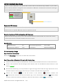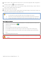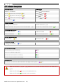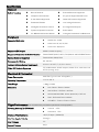
1
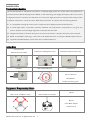
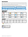
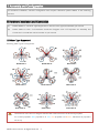
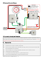
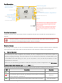
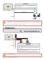
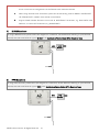
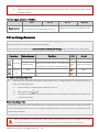
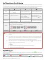
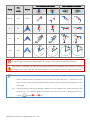
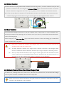
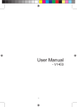
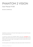
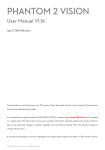
A2 Flight Control System User Manual V 1.10 2013.10.25 Revision For Firmware V2.0 & Assistant Software V1.1 & DJI Assistant App V1.1.13 Thank you for purchasing DJI products. Please strictly follow these steps to mount and connect this system on your aircraft, install the PC Assistant Software on your computer, as well as installing the DJI Assistant App on your mobile device. Please regularly check the web page of corresponding products on our website www.dji.com, which is updated regularly. Product information, technical updates and manual corrections will be available on this website. Due to unforeseen changes or product upgrades, the information contained in this manual is subject to change without notice. * This manual is for basic assembly and configuration; you can obtain more details and advanced instructions when using the Assistant Software. To assure you have the latest information, please visit our website and download the latest manual and current software version. If you have any problems that you cannot solve during usage, please contact your authorized dealer. © 2013 DJI Innovations. All Rights Reserved. 1 Content INTRODUCTION ..............................................................................................................3 PRODUCT INTRODUCTION ........................................................................................................3 IN THE BOX ...........................................................................................................................3 EQUIPMENT PREPARED BY USERS ..............................................................................................3 SYSTEM INTRODUCTION...........................................................................................................4 SYMBOL INSTRUCTION ............................................................................................................4 1 ASSEMBLY AND CONFIGURATION ................................................................................5 1.1 HARDWARE INSTALLATION AND CONNECTION ........................................................................5 1.1.1 Mixer Type Supported ...........................................................................................5 1.1.2 Hardware Connection Diagram .............................................................................6 1.1.3 Important for Assembly and Connection ...............................................................6 1.2 SOFTWARE INSTALLATION AND CONFIGURATION ...................................................................14 1.2.1 Install Driver and Assistant Software ..................................................................14 1.2.2 Configure using Assistant Software on a PC ........................................................14 1.2.3 Configure the control mode switch .....................................................................15 1.2.4 Configuration Checking .......................................................................................17 1.3 COMPASS CALIBRATION ...................................................................................................18 2 BASIC FLYING ............................................................................................................. 19 2.1CONTROL MODE INSTRUCTION ..........................................................................................19 2.2 FLYING ENVIRONMENT REQUIREMENTS ..............................................................................20 2.3 CHECK LIST BEFORE FLYING...............................................................................................20 2.4 POWER ON AND CHECK ...................................................................................................21 2.5 START MOTORS METHODS ...............................................................................................21 2.6 BASIC FLYING TEST .........................................................................................................22 3 PROTECTION FUNCTIONS SETTING ............................................................................ 24 3.1 FAILSAFE ......................................................................................................................24 3.2 LOW VOLTAGE PROTECTION..............................................................................................25 4 ADVANCED FUNCTIONS ............................................................................................. 26 4.1 IOC (INTELLIGENT ORIENTATION CONTROL) FUNCTION ..........................................................26 4.2 GIMBAL FUNCTION .........................................................................................................29 4.3 GEAR FUNCTION ............................................................................................................29 4.4 ATTITUDE CONTROL WHEN ONE MOTOR OUTPUT FAILS........................................................29 4.5 DJI ASSISTANT APP USAGE...............................................................................................30 APPENDIX ..................................................................................................................... 32 LED INDICATOR DESCRIPTIONS ................................................................................................32 SPECIFICATIONS ...................................................................................................................33 FAQ .............................................................................................................................. 34 USE WITH OTHER DJI PRODUCTS .............................................................................................34 CHANNEL MAPPING INSTRUCTIONS FOR PC ASSISTANT SOFTWARE ................................................36 RECOMMENDED MAPPING FOR FUTABA TRANSMITTER (MODE 2) USER.........................................37 SETTINGS OF GAIN VALUES FOR YOUR REFERENCE .......................................................................38 THE TRANSMITTER SETUP OF FUTABA ....................................................................................38 DISCLAIMER ................................................................................................................. 39 TRADEMARK ................................................................................................................ 39 © 2013 DJI Innovations. All Rights Reserved. 2 Introduction Product Introduction The DJI A2 Multi-Rotor stabilization controller is a complete flight system for various multi-rotor platforms for commercial and industrial AP applications. Based on the technology and design philosophy of DJI’s Ace series of high-performance controllers, the A2 offers you a brand new flight experience. Its flight mode setup provides a seamless transition for current Ace One, WKM AP professionals. The system has the following features: (1) It is integrated with high-precision sensor components and a high-performance GPS Receiver. (2) It utilizes high quality components precisely calibrated with temperature compensation in all gyros and sensors, industry renowned flight algorithm in autopilot and UAV field. (3) Designed with built-in vibration absorption, no extra mount frame or vibration absorption pad is required. (4) Based on the DESST technology, it has a built-in 16-channel Receiver, and supports DSM2 satellite receiver. (5) Optional DJI D-BUS Adapter can be used with a traditional Receiver. In the Box Controller Unit (Built-in Receiver DR16) PMU(Power Management unit) IMU(Inertia Measurement Unit) GPS-COMPASS PRO Accessories LED-BT-I Micro-USB Cable (1) Servo Cables (2) GPS Bracket Double side sticky pads. Equipment Prepared by Users Aircraft (Take Quad-rotor for example: Transmitter Red is nose, and Black is rear) (Take Mode2 for example) Others Battery DJI D-BUS Adapter Mobile Device © 2013 DJI Innovations. All Rights Reserved. 3 System Introduction The A2 flight control system uses the Control Unit at its core, which is connected with the IMU, GPS-COMPASS PRO、LED-BT-I、PMU and ESCs to complete the system. The system can achieve the height-lock and position-lock functions by using the IMU and the GPS, to control the aircraft. Please carry out the following procedures to finish assembly, configuration and flight-testing. Mount the A2 flight control system on your aircraft finish connection. Do basic flying test Configure the system using A2 Assistant software. Advanced functions: IOC, Gimbal, Gear FailSafe and Low-voltage settings Symbol Instruction General Symbol Forbidden(Important) Cautions Tips Reference GPS Satellite number Distance TX signal good TX signal lost Roll to left Roll to right Pitch up Pitch down LED Symbol (N) Meaning e.g. N=1 N=2 N=3 N=4 N=6 N=20 One Blink Two Blinks Three Blinks Four Blinks Six Blinks Twenty Blinks Continuous Blinks (3) means three Red blinks. (∝)LED blinks yellow and green alternatively. (N) Meaning e.g. N=∝ N=∝ Continuous Solid on (∝) means Continuous Blue Solid on. © 2013 DJI Innovations. All Rights Reserved. 4 1 Assembly and Configuration For hardware installation, software configuration and compass calibration please adhere to the following sections. 1.1 Hardware Installation and Connection (1) Please adhere to “1.1.1 Mixer Type Supported” to choose a mixer type and assemble your aircraft. (2) Please adhere to both “1.1.2 Hardware Connection Diagram” and “1.1.3 Important for Assembly and Connection” to install and connect all units on your aircraft. 1.1.1 Mixer Type Supported Following Mixer Types are supported. Quad-rotor I Quad-rotor X Hexa-rotor I Hexa-rotor V Hexa-rotor IY Hexa-rotor Y Octo-rotor I Octo-rotor V Octo-rotor X The direction of the arrow in diagram indicates the rotation direction of the motor/propeller. For coaxial propellers: Blue propeller is at TOP; Red propeller is at Bottom. Otherwise all propellers are at top. © 2013 DJI Innovations. All Rights Reserved. 5 1.1.2 Hardware Connection Diagram Important ESC CAN-Bus, it provides power supply and communication. A2 can automatically identify the device connected. CAN1 and CAN2 ports are working independent, device connected are non-interchangeable. E.g. IMU and GPS-COMPASS PRO to CAN1; LEDBT-I to CAN2; PMU to CAN1 or CAN2. 90o Supply power for all ports on both sides of controller unit. 2S~6S Battery 1.1.3 Important for Assembly and Connection This section describes all device port functions, assembly requirements, connection requirements and tips during usage. Also the linking procedures between the built-in Receiver DR16 and your Transmitter. It is very important for the first time usage, please read all text carefully. (1) Controller Unit The Control Unit is the core component of the A2 flight control system: (1) M1~M8 are used to connect to the ESCs of the aircraft. (2) The built-in Receiver DR16 is based on DJI DESST technology, which can be used with the Futaba FASST series and DJI DESST series Transmitter. (3) CAN1 and CAN2 ports are working independently and should connect to different modules. (4) 4 independent and configurable outputs. (5) It is compatible with the external Receiver, e.g. DSM2 satellite Receiver. (6) Use the optional DJI DBUS Adapter to support the traditional receiver. © 2013 DJI Innovations. All Rights Reserved 6| Port Description Indicate the linking status Link button of Built-in receiver DR16 and transmitter Multi-function PWM output channels, can directly give output signal from the Receiver if mapped to a Receiver channel* Connect to ESC Reserved To S-BUS Receiver BEC,Connect to X1 of PMU for voltage detection IMU GPS-COMPASS PRO iOSD MARK II, Z15 from DJI To DSM2 satellite Receiver To PW port of PMU LED-BT-I 2.4G DATA LINK from DJI Antenna *If the Gimbal function is enabled in Assistant Software, F2/F3 can only be used for gimbal Pitch/Roll control, which means F2/F3 cannot be mapped to any other Receiver channel. *If the Gear function is enabled in Assistant Software, F1 can only be used for gear switch control, which means F1 cannot be mapped to any other Receiver channel. Mounting Requirements: Install the Controller Unit in the proper position to make sure the ports are accessible. No specified direction is required. Place the antennas in an open space under the aircraft, DO NOT block them. Position the heads of two antennas at a 90-degree angle. DO NOT bend or wind them. Receiver System The A2 flight control system can use its own built-in Receiver, and also can support external receivers. Whatever type of Receiver is used, please make sure that the Receiver and Transmitter is linked correctly before use. A. Built-in Receiver For enhancing the system integration and reliability, the A2 is integrated with a 2.4G receiver based on frequency hopping technology. The built-in Receiver can be used with the Transmitter of Futaba FASST series or DJI DESST series after linking. For users, you are only asked to carry out the link procedures, no extra requirement for connection. Please carry out the following procedures to finish the Link process, and the configuration in the A2 Assistant software->Basic ->R/C ->Receiver Type. Select the DR16 option. During use, you may see the following LED indication, please do the operation according to the table below. LED (∝) (∝) (∝) Description Operation Signal from Transmitter has been detected by the Receiver, but not matched. Link operation required No Transmitter signal is received, e.g. the flight control system is powered on but the Transmitter is powered off. The Receiver and Transmitter have been linked to each other successfully. © 2013 DJI Innovations. All Rights Reserved 7| Switch on Can work normally Link Procedures 1. Turn on the transmitter, it begins to send signals after 1.5secs. 2.Power on the flight control system, configure the Receiver type as DR16 in the Assistant software. 3.Press the LINK button, hold for 2secs, wait until the LED blinks Red . 4.Release the LINK button, the LED turns Green on after successfully linking. 0.5m<Distance<1cm The DR16 Receiver is compatible with the Futaba transmitters which have optional FASST MODE MUL T, MLT2 or 7CH. Users can find out the available Futaba transimitters and configuration requirments a dhere to the FAQ->The Transmitter setup of FUTABA. B. DSM2 Satellite Receivers If using DSM2 satellite Receivers, please follow the diagram for connection, set the Receiver referring to your Receiver manual, and select the Receiver type as DSM2 in the Assistant software->Basic->R/C-> Receiver Type. DSM2 satellite Receiver DSM2 satellite Receiver Linking procedures 1. Power on the flight control system, the Transmitter should be turned off. 2.Set the Receiver type as DSM2 in the Assistant software. 3.Press and hold the LINK button on the controller unit the LED blinks red and the indicators on the Receivers blink too. Then release the LINK button the Receiver will be ready for linking. 4.Press and hold the linking button on the Transmitter then turn on the Transmitter to start linking, release the button after the Transmitter is displayed Linked or the indicators on the Receivers are solid on. 5.The LED on the controller unit will be solid green on after linking successfully. Notes for the DSM2 users: It is no need to enable the Failsafe function in the Transmitter. Once the Receiver loses the signals © 2013 DJI Innovations. All Rights Reserved 8| from the Transmitter, the controller unit will enter into Failsafe automatically, and the aircraft will hover or Go-home as configurations of the Failsafe in the Assistant software. When using the dual-mode Transmitter, please set the transmiting mode as DSM2 in SYSTEM SET UP->FRAME RATE ->MODE, which should not be DSMX. Support DSM2 satellite Receivers used with all SPEKTRUM Transmitters, e.g. DX6I DX7S DX8 DX18 etc., as well as JR Transmitters, e.g. DXS9II DXS11. C. S-BUS Receivers If using S-BUS Receivers please follow the diagram for connection, set the Receiver referring to your Receiver manual, and select the Receiver type as D-BUS in the Assistant software->Basic->R/C-> Receiver Type. S.BUS D. S-BUS Receiver PPM Receivers If using PPM Receivers please follow the diagram for connection, set the Receiver referring to your Receiver manual, and select the Receiver type as PPM in the Assistant software->Basic->R/C-> Receiver Type. PPM © 2013 DJI Innovations. All Rights Reserved 9| PPM Receiver E. Traditional Receivers If using Traditional Receivers, the DJI D-BUS Adapter is required. Please follow the diagram for connection, set the Receiver referring to your Receiver manual, and select the Receiver type as D-BUS in the Assistant software->Basic->R/C-> Receiver Type. 8 7 6 5 4 3 2 1 Traditional Receiver Important © 2013 DJI Innovations. All Rights Reserved 10 | · When you use a traditional receiver, DJI D-BUS ADAPTER is required. Put the switch to the “I” stop, and power on the system, the LED should be red on; otherwise, keep the switch at “I” stop and then power cycle the system. · At the “I”stop, the D-BUS ADAPTER is converting the PWM signal from traditional receiver to S-BUS signal. (2) IMU (Inertial Measurement Unit): Built-in inertial sensors, for the measurement of aircraft attitude; built-in pressure sensor for the detection of aircraft altitude. Should be connected to the CAN1 port of the Control Unit, and be mounted according to the required location and orientation. The IMU has been calibrated before shipping, it should be used under the specified temperature; otherwise the temperature may have an effect on the IMU performance. Working environment temperature: -5oC ~60oC Storage environment temperature:<60oC Orientation Requirements: Please mount the IMU as one of the following options. Configure in the A2 Assistant software ->Basic ->Mount -> IMU, and select the matched option. Pointing Forward Pointing Backward Pointing to Left Pointing to Right Location Requirements: Fix with double faced adhesive tape. Center of Gravity (1) The top side should be facing up. DO NOT mount upside-down. (2) DO NOT cover the ventilation holes, keep them unblocked and clean. (3) Take heat preservation measures if working in cold weather. (1) Mount the IMU at a low vibration position and the sides of the IMU should be precisely parallel to the aircraft body. Based on our experience, there is less vibration near the aircraft’s center of gravity. (2) NOT water-proof or oil-proof. (3) Check the double faced adhesive tape regularly to make sure that the IMU is fixed firmly. There is a CAN-Bus connector, which can be used to connect to the GPS-COMPASS PRO or other DJI product. © 2013 DJI Innovations. All Rights Reserved 11 | (3) GPS-COMPASS PRO GPS-COMPASS PRO module has a built-in GPS and compass. The compass is used for geomagnetic field measurement. It should be mounted according to the required location and orientation. Compass calibration is required before use. DO NOT use and store the compass in the ferromagnetic material environment. Mounting Procedure: a) Use the epoxy resin AB glue to assemble the GPS bracket first. The longest one is recommended. b) Mount the bracket on the aircraft first, and then fix the GPS-COMPASS PRO on the plate of the bracket (using the 3M sticky pads provided). Mount Requirements: The arrow is pointing to the nose direction. Keep it parallel to the aircraft Use the GPS bracket, and keep it away from other electronic equipment Usage Requirements (1) The DJI logo should be facing the sky, with the orientation arrow pointing directly to the nose direction; otherwise it may lead to take off failure. (2) Fly the aircraft in an open space without buildings or trees; otherwise it may have an effect on the GPS. (3) The compass is sensitive to magnetic interference, should be far away from electronic devices, otherwise it may lead to abnormal flying. (4) Please always keep the compass module away from magnet fields. Otherwise it may damage the compass module and lead the aircraft to work abnormally or even be out of control. © 2013 DJI Innovations. All Rights Reserved 12 | (4) PMU (Power Management Unit) The PMU provides dual BEC’s: (1) Connect the battery to the PMU module to supply power for the whole Flight Control System via the PW port (supply power not more than 2A). (2) Connect the PMU to the X1 port of Controller Unit for voltage monitoring, for flight safe guard during flying. In addition, there are two CAN-Bus ports for LED-BT-I connection and other DJI products (e.g. DJI 2.4G Data Link). Port Description PX Port, connect to the X1 port of Controller Unit V-SEN, Output 0V ~ + 3.3V Working status indicator Green on is normally working To negative pole of power To positive pole of power VCC, Output 3A@5V Input voltage range: 7.4V~26V GND CAN-Bus port Connect to CAN1 or CAN2 port of Controller Unit, CAN2 is recommended. Mounting Requirements: No need to mount in a particular orientation. But choose a ventilated place to mount the PMU for cooling. (5) LED-BT-I The LED-BT-I has integrated LED Indicator, Bluetooth and USB port: (1) The LED is mainly for flight control system status indication during flying (e.g. Control Mode). (2) Bluetooth is used for real-time communication with your mobile device (e.g. iPhone), to realize parameter configuration on a mobile device. For parameter configuration using a mobile device, it is required to install the DJI Assistant App on the mobile device. When you mount the LED-BT-I, please make sure the side with ANT LOGO is unsheltered after mounting. (3) In addition, there is a Micro-USB port, make sure it is mounted for convenient connection. Port Description: Bluetooth status indicator Abnormal Normal Communicating Micro-USB port:used to connect to the PC for Assistant software configuration and upgrade Indicator of autopilot system Antenna of Bluetooth Mounting Requirements: Mount in a good place to make sure the LED is visible during flying. Antenna of Bluetooth should be unobstructed. © 2013 DJI Innovations. All Rights Reserved 13 | 1.2 Software Installation and Configuration Configure the A2 flight control system in the Assistant software please adheres to this section. Users are required to configure every item in “Basic” page when use the A2 flight control system for the first time. 1.2.1 Install Driver and Assistant Software 1. Download 2.Connect 3.Install Driver 4.Install Software Download the driver Connect the Run the driver Run the assistant installer and assistant LED-BT-I module and installer and follow software installer and software installer PC via a Micro-USB the prompts to finish follow the prompts to from DJI website. cable. installation. finish installation. Assistant software supports only Windows operating systems (Win XP, Win7, Win8 (32 or 64 bit)). 1.2.2 Configure using Assistant Software on a PC The USB port can supply power during configuration, no additional battery is required. Note that the USB port can supply power not more than 500mA, an additional battery is necessary if connection failure or intermittent working. Run the assistant software, and follow the built-in guide to carry out the configuration. Note that you may be asked to register for first time use. 4 3 2 1 Menu Setting Options Built-in Guide 1. View 2. Restore &Upgrade 3.Set 4.Check Click “Info” to view Enter “Tools” to restore default Enter “Basic” page. Enter “View” user information settings. And check whether the Set the Aircraft, page to check all and software firmware is the latest. Mounting, RC, Gain” basic settings. version etc. © 2013 DJI Innovations. All Rights Reserved in each tab. 14 | “RC STATUS” description: Normal- Communication between the transmitter and receiver is well. Disconnect- The A2 Flight Control System is power on, but the transmitter is power off. RC-LOST- RC signal is lost, or the transmitter is power off after switch on Abnormal - Other situations. 1.2.3 Configure the control mode switch Users should configure the control mode switch in the Assistant software in the following page. Only the mode switch has been set correctly, the control mode displayed in the left bottom corner will be the same to the control mode pointed by the cursor on the channel U. Configuration steps Exzambles Step 1. Power on your Transmitter, map a 3-position switch on the transmitter to the U channel of Fight controller as the control mode switch, of which two positions are default as Atti. and GPS Mode and the other position is optional, users can set as Atti. or Manual Mode. © 2013 DJI Innovations. All Rights Reserved 15 | Step 2. Toggle the control mode switch to its three positions, accordingly the cursor will move to some control mode. Step 3. Power off the Transmitter, the Failsafe will be enabled and the cursor will point to any area out of the control modes. Step 4. If all steps above are realized, that indicates the control mode switch is set successfully. Important In step2, if the cursor doesn’t point to the correct control mode area (e.g. the following figures), that indicates abnormal control mode switch configuration. Users must re-configure the Endpoint and FailSafe functions in the Transmitter to make the cursor right point to the control mode switch and the control mode areas become blue. © 2013 DJI Innovations. All Rights Reserved 16 | 1.2.4 Configuration Checking 1 7 2 3 4 8 5 9 10 11 6 12 *Fig. above for reference only, please adhere to actual GUI. Check List ① ② ③ ④、⑤ ⑥ ○ ⑦~ 11 ○ 12 Description Check the IMU orientation direction. Check the Mixer Type of aircraft. Make sure the motors are rotating normally, and propeller installation is in correct direction. The Receiver type is correct. Check the basic and attitude gains. Move the sticks to test whether the cursors moves following the sticks. Toggle the “U” switch to test the control mode setting. Advanced configuration, users can configure it according to their requirements after reading the manual. Check the Channel Map between the Transmitter and A2 flight control system. © 2013 DJI Innovations. All Rights Reserved 17 | 1.3 Compass Calibration The Compass can assistant the GPS to position the aircraft, which is very important during flight. As we know, the compass is very sensitive to electromagnetic interference, which will cause abnormal compass data, and lead to poor flight performance or even flight failure. Compass Calibration MUST be done for the first time use. It is recommended to calibrate the compass outdoors after the Controller Unit finds 7 or more GPS satellites. Regular calibration enables the compass to keep optimal performance. Calibration Cautions (1) DO NOT calibrate your compass where there is strong magnetic interference, such as magnetite, car park, and steel reinforcement under the ground. (2) DO NOT carry ferromagnetic materials with you during calibration, such as keys or cell phones. (3) Compass Calibration is very important; otherwise the flight control system cannot work. Calibration Procedures Choose an open space to carry out the following procedures. Quickly flip the control mode switch 360o Rotate the aircraft horizontally 360oRotate the aircraft vertically (Nose downward) Manual* Start cali GPS GPS->Manual->GPS Flip 6~10 times Control Mode LED Start horizontal calibration Start vertical calibration Succeed Re-calibrate Manual *You can also use the ATTI 1 or ATTI 2 to replace the Manual during switch flipping. Fail GPS GPS->Manual->GPS once Situations that require recalibration Situations Descriptions Compass Data abnormal LED blinks yellow and green alternatively( Flying field altered Flying field has changed over a long distance. (∝)). The mounting position of GPS-COMPASS PRO module changes. Mechanical alteration Electronic units such as Controller Unit, CAN-HUB, battery etc. have been added, removed, remounted or other alterations. Mechanical structures of the aircraft has changed Drifting during flying Evident drifts occurred in flight such as the aircraft doesn’t fly straight Attitude errors LED often blinks error indicator when the aircraft turns around. © 2013 DJI Innovations. All Rights Reserved 18 | 2 Basic flying Read this section before basic flight testing. 2.1Control Mode Instruction The aircraft performs differently when using different control modes. Please read the following table to know the different control modes, which may help you to achieve a more involved flight experience. Control Mode 3 Control Mode 2 GPS ATTI. 2 Command Roll and Pitch Throttle Manual YES Linearity Yaw Control Mode 1* ATTI. 1 Control the aircraft to rotate in clockwise and counter clockwise direction. Maximum rudder angular velocity 150°/s Aircraft attitude control; Mid point of stick is for 0˚ Max-angular velocity is 150°/s. attitude, and its endpoint is 35˚. No attitude angle limit. Aircraft height control. Maintain the altitude best above 1 No altitude locking when the meter from ground when the throttle stick is in mid position. throttle stick is in mid position. All Sticks Lock position if GPS signal Only attitude stabilizing. No Released is adequate. position locking. Keep original attitude. When GPS signal has been GPS Lost lost for 3s, system enters --- --- CL None ATTI. Mode automatically. IOC Supported CL/HL/POI The flight control system will enter FailSafe The flight control system will enter FailSafe Mode if the Transmitter signal is lost and no FailSafe Mode if the Transmitter signal is Protection matter if Transmitter signal recovers or not, lost and the system will exit Failsafe once system will not exit failsafe mode automatically. the signal recovers. GPS Involved YES NO Low-voltage LED alert with Descending or Go Home & Protection Landing precautions Environment Open flying field; Narrow Space; recommended Good GPS signal GPS signal bad Only LED alert Regain control in emergency *Default is Manual; users can set to ATTI.1 in Assistant software. The biggest difference between ATTI.1 and ATTI.2 is that they are working differently in the protection situations. © 2013 DJI Innovations. All Rights Reserved 19 | 2.2 Flying Environment Requirements (1) Before use of the product, please accept some flight training (Using a simulator to practice flying, getting instruction from a professional person, etc.). (2) DO NOT fly in bad weather, such as rain or wind (more than moderate breeze) or fog. (3) The flying field should be open without tall buildings or other obstacles; the buildings of steel structure will interfere with the compass. (4) Keep the aircraft away from obstacles, crowds, power lines, trees, lakes and rivers etc. (5) Try to avoid interference between the remote control Transmitter and other wireless equipment. (No base station or cell tower around) (6) The flight control system can’t work at the South Pole and the North Pole. (7) All parts must be kept out of the reach of children to avoid CHOKE HAZARD; if a child accidentally swallows any part you should immediately seek medical assistance. 2.3 Check List before Flying Double check the following list, otherwise, if any one of the following items is wrong it may lead to flight accident. (1) All parts are in good condition, no ageing or damaged components (2) Motor rotating direction (3) Propeller mounting direction (4) Mixer Type set in assistant software (5) IMU and GPS-COMPASS PRO mounting direction (6) Transmitter channel mapping and sticks movement direction correct (7) Compass calibration (8) ESC connection (9) IMU and GPS-COMPASS PRO firmly mounted In addition, check the following items to make sure the system can work. (1) The Transmitter battery is fully charged. (2) The aircraft battery is fully charged. (3) Do not over load the aircraft. © 2013 DJI Innovations. All Rights Reserved 20 | 2.4 Power on and Check (1) Control mode LED indicator Power on the Transmitter and flight control system. Toggle the control mode switch to different positions. Control Mode LED indicator Control Mode GPS Switch LED Manual ATTI 2 (Stick not in midpoint (2)) (Stick not in midpoint (2)) No LED indicator Put the Control Mode switch to GPS position for basic flying test. Set Note: when the GPS signal LED indicator is bad or worst ( (2) or (3)) and lasts for more than 3secs, the flight control system will enter into ATTI2 Mode. (2) GPS signal LED indicator GPS signal indication blinks after every Control mode indication. We suggest to fly when GPS satellites are more than 5. GPS signal LED indicator Worst ( < 5): (3) Bad ( = 5): (2) Well ( = 6): (1) Best ( > 6):No indicator 2.5 Start Motors Methods CSC (Combination sticks commands) is used to start/stop motors instead of just pushing the throttle stick. CSC 2 CSC 1 CSC 3 CSC 4 Under the conditions stated below, the motors will stop in ATTI 1/ ATTI 2/GPS mode: (1) The throttle sticks is under 10% for more than 3secs after motors start. (2) The throttle sticks is under 10% for more than 3secs after landing. (3) The throttle sticks is under 10% for more than 3secs and the inclined angle of aircraft exceeds 70°。 © 2013 DJI Innovations. All Rights Reserved 21 | 2.6 Basic Flying Test Carry out the following procedures to complete the basic flight test. 1. Wait the GPS signal to be well LED Place the aircraft away from you and others at least 3 meters and wait the or no Red LED ≥6. 2. Start motors and takeoff aircraft. LED Execute CSC to start motors; all sticks back to midpoint as soon as motors start, then push the throttle stick to take off the aircraft, meanwhile the home point is recorded. NOTE: 30secs after power on; 10secs after ≥6; Motors have been started, auto-record the (∝) position as home point at the first time the throttle stick is raised After the home point is recorded successfully and the distance from aircraft is less than 8m, LED indicator will blink 6 violet continually. Note: only when GPS signal is good (no Red (6) LED) LED indicator will blink 6 violet continually. 3.Operate sticks to control the flying attitude of the aircraft during flight Transmitter (Mode2) Aircraft Operations Push Throttle sticks to control the aircraft Throttle to elevate and descend. The aircraft can Stick lock to an altitude when the throttle stick is at midpoint. Push the yaw stick to rotate the aircraft in Yaw Stick clockwise or counter clockwise direction. Push roll stick to control the aircraft left or right, pitch stick to control forward or Roll Stick backward. When both roll and pitch sticks are at midpoint: (1) GPS mode: the aircraft will be stabilized and locked in horizontal Pitch position. (2) Stick ATTI 1/ATTI 2 mode: the aircraft will be stabilized but unlocked in horizontal position. © 2013 DJI Innovations. All Rights Reserved 22 | 4.Hover In GPS mode,the aircraft will hover when the throttle/yaw/roll/pitch sticks are all released at mid-point. 5.Landing Use the throttle stick to control the landing speed, try to land your aircraft gently to avoid shock or crash. Please refer to the next section “Protection Functions Setting” to take precautions. (1) Low voltage alert: yellow quick flashes or red quick flashes. (2) FailSafe: LED indicator blinks blue. Moreover, you may come across the following abnormal situation, please carry out the operation below. (3) Compass data is abnormal; the LED blinks yellow and green alternatively. Please re-calibrate the Compass. (4) IMU data is abnormal, the LED blinks four green. Please contact your dealer. © 2013 DJI Innovations. All Rights Reserved 23 | 3 Protection Functions Setting Set protection in the Assistant software ->Advanced page. FailSafe and Low voltage protections are required. 3.1 FailSafe FailSafe works when the Transmitter (TX) signal is lost, the flight control system will automatically control the aircraft to reduce injuries or damage. TX Descriptions signal ≥6( Home 30secs later after power on; 10secs later after Point Motors have been started; auto-record the position as home point at the first time (HP) the throttle stick is raised. or no Red LED); Flight control system can automatically control the aircraft after Transmitter signal is ≥ lost. It should be set in Assistant software->Advanced->F/S, while Hover, Go-Home or FailSafe 6 Alt Go-Home is optional. Additionally, a Go-Home switch can be enabled. Go Home switch can be used to trigger a “go home” without FailSafe. If One-Key One-Key Go Home is enabled during flying, you no longer have control of the aircraft, the LED Go Home blinks in its Control Mode. If One-Key Go Home is disabled, you regain the control at once. If already in a Failsafe condition, then the switch will not work. Failsafe and Go Home procedures 1 Record Home Point (HP) 2 Confirm Home Point 3 Transmitter Signal Lost ≥7 <8m LED LED (∝) 4 Signal Lost Lasts 3secs. LED (6) 5Go Home(20m can be customized) (∝) 6 Landing after Hovering 15secs Height over HP>20m 20m Elevate to 20m Height over HP<=20m LED (∝) (1) LED (∝) LED (∝) The aircraft will not go home (only attitude stabilizing) in the condition that <6 or GPS is not working, even if Transmitter signal is lost or Go Home switch is triggered. (2) It is recommended to set the Go Home switch in the Assistant software. Users are suggested to enter Failsafe and go home by using the Go Home switch rather than turning off the Transmitter in © 2013 DJI Innovations. All Rights Reserved 24 | emergency situations. (3) Make sure there are no obstacles during aircraft go home and users are familiar with the methods to regain control. How to regain control in FailSafe GPS Regain control ATTI 2 You have to toggle the control mode switch once to regain control if the signal recovers, y. ATTI 1 Manual Regain control as soon as signal recovers. 3.2 Low Voltage Protection Low voltage protection is used to alert low battery voltage during flight; in this case, users should promptly fly back the aircraft and land to avoid unexpected damages. To use this function please set in Assistant software->Advanced->Voltage page to configure two voltage levels. Protections First level Option Selected Conditions LED ---- GH & Landing Make sure the home point is recorded and no obstacles in going home and landing path. LED (∝) Aircraft None (∝) Go-Home & Landing Second LED ---- (∝) level Descending ---- (∝) Descending directly None Go-Home & Landing Usage Tips (1) The home point recorded is the same in both Failsafe and Low voltage protection. The aircraft will not go home in the following cases : a) Control mode is in Control Mode 1 (Manual or ATTI 1) b) GPS signal is bad ( c) The distance between aircraft and the home point is less than 25m, and the height over the Home <6) point less than 20m. Descending Usage Tips The aircraft will not hover when the throttle stick is at the mid point. Push the throttle stick to 90% of endpoint, the aircraft will still ascend slowly if you continue to pull the throttle stick, and the control of Pitch, Roll and Yaw are the same as before. Please pay attention to the LED alert of low voltage and make sure the power is enough for go home and landing. Insufficient power reserve will cause the aircraft to crash and other consequences. © 2013 DJI Innovations. All Rights Reserved 25 | 4 Advanced Functions IOC and Gimbal functions of A2 and how to use A2 Assistant app via a mobile device. 4.1 IOC (Intelligent Orientation Control) function IOC Help users to set the Flying direction; Should be enabled in Assistant software. Flying direction The flying direction of aircraft when pushing the Roll and Pitch sticks. Forward direction The flying direction of aircraft when the pitch stick is pushed forward. IOC is disabled. Forward direction is pointing to the nose direction and changes Normal flying along with the nose. Course Lock. Its forward direction is pointing to the nose direction when CL flying recording, which is fixed until you re-record it or exit from CL. Home Lock. Record a Home Point (HP), push Pitch stick to control the aircraft HL flying far from or near to the HP. Point of Interest. Record a point of interest (POI), the aircraft can circle around POI flying the POI, and the nose always points to the POI. Conditions of IOC function Flying IOC Setting Control Mode Normal ---- ---- CL Enabled Not in Manual HL Enabled POI Enabled GPS-COMPASS GPS Satellites Distance Limits ---- Basic to control mode None Compass None None PRO Required GPS GPS GPS ≥6 GPS ≥6 Aircraft Aircraft ≥10m 5m~500m HP POI Step 1 IOC switch setting Please enable the IOC function in Advanced->IOC page of Assistant software. Then choose a 3-positon switch on the Transmitter to set as IOC switch, which is used to select the different IOC modes and manually record the Forward direction, HP and POI recording. Below are the three options of IOC switch setting which may be configured in the Assistant software. Switch positions A B C 1 OFF OFF OFF 2 CL CL POI 3 HL POI HL © 2013 DJI Innovations. All Rights Reserved 26 | Step 2 Forward Direction, HP and POI Recording After you enable the IOC in assistant software, the flight control system will record the forward direction and home point automatically after power on, if the recording conditions are met. You can Manually re-record the forward direction, home point and POI during flying. Read the following table for the recording method details. CL Record a direction as Forward Aims direction HL POI Record a position as HP Record a position as POI 30secs after power on; 10secs Conditions 30secs after power on ≥6; later after 10secs later after Motors have been started. Automatically 30secs after power on; Automatically record at Automatically record at the first 30secs after power on time you push the throttle stick ≥6. No Automatic record method According to any option of IOC switch setting, quickly toggle the switch between adjacent positions 3-5 times to record manually. Manually 1 A Forward direction 2 Successful (1) B Forward direction C POI 2 A B C 3 HP POI HP (20) (20) (20) DO NOT toggle the switch between the 1 and 3 positions frequently, which may re-record the position 2. (2) HP is used not only in IOC, but also in Failsafe and Low voltage for go home and landing. The flight control system will automatically record the HP even if IOC function is disabled in Assistant software but Forward direction and POI can be recorded only after IOC is enabled. (3) Once the Home Point is recorded successfully, LED will blink (6) continually under the following conditions. All conditions must be true. 1. ≥7. 2. Distance between aircraft and the recorded home point is less than 8m. 3. Current control mode is in GPS or ATTI 2. Step 3 IOC flying test Please study the following diagram then make an IOC flying test. IOC LED indicator blinks ( (2) means stick(s) not at the midpoint) HP POI Flying direction © 2013 DJI Innovations. All Rights Reserved Forward direction 27 | Route Auxiliary line CL CL HL HL POI POI None 50 5~ > 10 0m 50 5~ 0m >10m OFF > 10 Normal Record >10m switch Pitch stick control of aircraft m Flying Roll stick control of aircraft m IOC 50 5~ 0m 50 5~ 0m DO NOT toggle the IOC switch frequently in HL flying to avoid re-recording the HP unwittingly. IOC function is available only when all the required conditions are satisfied. If any condition is omitted the flight control system will exit IOC. Please keep an eye on the LED to know the current control mode. (1) It’s recommended to start the HL flight when the aircraft is >10m away from the HP. If starting the HL when the distance between aircraft and HP is less than 10m and it’s the first time you start HL after power on, then the flight control system will only enter HL after flying out of the 10m range. (2) During HL flying if one of the following conditions occur, the flight control system will exit HL and enter into CL: the aircraft is within of 10m from HP; the control mode is changed to ATTI 1 or ATTI2; <6(LED (2) or © 2013 DJI Innovations. All Rights Reserved (3)). 28 | 4.2 Gimbal function Connect the servos of your gimbal to the Controller Unit as the fig. below,roll servo connects to F3 port and pitch servo connects to F2, and configure in Advanced->Gimbal page in the Assistant software. No Receiver channel is asked to be mapped for the F2 or F3 port if gimbal function is enabled in the Assistant Software. Note: Even you map Receiver channels to F3 and F2 (Which are shown as D3 and D2 in the Assistant Software -> Channel Mapping), the F3 and F2 will not give output signals from the mapped Receiver channels. F2 Roll Pitch F3 4.3 Gear function Once enable the Intelligent Gear function, the gear is default down on the ground or in case of emergency (e.g. motor failure tolerance, auto landing); you can control it to be up or down by a switch when the aircraft altitude is above 5m during flight. Please configure in the Advanced->Gear page in the Assistant software. Connect the landing gear of S800 EVO to the Controller Unit as fig. below. (1) Make sure to enable and configure the Intelligent Gear function in the Assistant software first, and then connect the gear to the F1 port. (2) The Gear channel is required to be mapped with a channel on Receiver if the Intelligent Gear function is enabled in Assistant Software, and the F1 port will give outputs for retracting control. (3) Once you map the Gear channel, F1 port will give output signals from the controller for retract control. Otherwise, even the Intelligent Gear function is enabled; F1 will give output from D1 (it’s necessary to map the D1 channel with a channel on Receiver as your demands). 4.4 Attitude Control When One Motor Output Fails For Hexa-rotor, including Hexa-rotor I, Hexa-rotor V, Hexa-rotor IY and Hexa-rotor Y, the aircraft with A2 flight control system is attitude controllable when one motor output fails. Select Course lock or home lock mode for flying the aircraft into a safe area to land when the aircraft is far away or the attitude can’t be recognized. © 2013 DJI Innovations. All Rights Reserved 29 | 4.5 DJI Assistant App Usage There is a built-in Bluetooth in the A2 LED-BT-I module. With a DJI Assistant App installed on your mobile device, remote parameter configuration can be obtained via Bluetooth communication between the A2 Flight Control System and the mobile device. Bluetooth status indicator Abnormal Normal Communicating Antenna of Bluetooth Supported iOS devices iPhone 4s, iPhone 5, iPhone 5s, iPod Touch 5, iPad 3, iPad 4, iPad air, iPad mini iOS6.1 or above is required. Bluetooth version is required to be 4.0. Required versions of DJI Assistant App & Firmwares Require DJI Assistant App version 1.1.13 or above and the firmware of A2 Controller Unit version 2.0 or above, as well as the firmware of LED-BT-I module version 2.0 or above. Specifications Bluetooth version 4.0 Environment temperature -10℃~+50℃ Communication distance 50m Consumption 240mw(0.04A@6V) DJI Assistant App Usage Step 1 Download and installation Search the DJI Assistant in App store on mobile device and install it. Step 2 Connect the A2 Controller Unit and the DJI Assistant App 1. Prepare an iOS device supported 4.0 Bluetooth, and then enable the Bluetooth function on the mobile device. 2. Power on the transmitter and the A2 Flight Control System, make sure the Bluetooth Status Indicator is solid Green ( 3. ). Run the DJI Assistant App. You may be asked to register through internet when first login (the account of PC Assistant software is OK for login); follow the tips to set Main Controller name and password. 4. Observe the indicators on the left bottom of the software. ( connection indicator and communication indicator) On the DJI Assistant App, if the communication indicator is check the connections and driver installation; otherwise if the indicator is blinking © 2013 DJI Innovations. All Rights Reserved 30 | , please double , go to next step. 5. Select the “Basic” option. Please follow step-by-step for your first-time-configuration. Basic configuration is necessary. Click the icon 6. to get the configuration details. You can click the “Advanced” option for more parameter settings. Advanced setting is optional. There are Motor, F/S, IOC, Gimbal, Voltage, Limits, Gear, etc. 7. Check all parameters in the View page. 8. Select “More” to obtain more details. Including: Restore MC default settings, Accounts, Main Controller List, Information, wiki, Rate DJI Assistant, FAQ, Feedback, About. 1. Make sure to upgrade the LED-BT-I module to the latest firmware via the PC Assistant software on a PC before you use the DJI Assistant App with the A2 Flight Control System. 2. Every time you run the DJI Assistant App, the App will search the Controller Unit automatically. 3. The gain value displayed on Mobile Device and PC may be a little different, that is OK for use. Step 3 Flying Test Procedures 1. Get the aircraft ready, run the DJI Assistant and make sure it is connected with the main controller. (The indicators on the DJI Assistant are ) 2. Start the motors. 3. The “View” page shows the relative parameters real-time when flying. 4. Go to the “Basic” and click into the “Gain” page to set the values of all gains real-time during flying. 5. Go to the “Basic” and click into the “Tool” page to view the values of IMU & Compass real-time during flying. 6. Finish the flying and land your aircraft. Only the parameter referred above can be changed during flying. Others can be configured after landing. © 2013 DJI Innovations. All Rights Reserved 31 | Appendix LED indicator descriptions Control mode GPS signal Manual:No indicator Best ( ATTI1: (1) (sticks not in mid-point (2)) Good ( ATTI2: (1) (sticks not in mid-point (2)) Bad ( GPS: (1) (sticks not in mid-point (2)) Worst ( Ground Station: > 6): No indicator = 6): = 5) : < 5): (1) (2) (3) (1) Flight Attitude Attitude good: No indicator Attitude status bad: Attitude status bad, hover/sticks at mid recommended: (2) (3) IMU data lost, calibrate IMU needed: (4) Compass calibration Horizontal calibration (∝) Calibration Failed (∝) Vertical calibration (∝) Abnormal Compass Data (∝) Low voltage alert First level alert (∝) Second level alert (∝) FailSafe mode During the FailSafe (∝) IOC Recording Record home-point successfully (20) Aircraft is in the 8m range of HP (6) Record forward direction successfully (20) Record a Point Of Interest successfully (20) Bluetooth A2 Assistant is connected / disconnected to the flight control system When the LED blinks (2) or (3), please hover or land the aircraft and wait for the white LED to go off. When the LED blinks (3), it is not recommended to fly. When the LED blinks (4), please contact your dealer. © 2013 DJI Innovations. All Rights Reserved (∝) 32 | Specifications General Built-In Functions Built-in Receiver External Receiver Supported Multiple Control Modes 9 Types of Supported Multi-rotor 2-axle Gimbal Supported Other DJI Products Supported Enhanced FailSafe Low Voltage Protection Intelligent Orientation Control 4 Configurable Outputs Dynamical Systems Protection Sound Alarm PC & Bluetooth Ground Station Configure Parameters Via Bluetooth Peripheral Supported Multi-rotor Quad-rotor: I4, X4 Hexa-rotor: I6, V6, Y6, IY6 Octo-rotor: X8, I8, V8 Supported ESC output 400Hz refresh frequency. Supported Transmitter for Built-in Receiver Futaba FASST (MULT, MLT2, 7CH) Series and DJI DESST Series External Receiver Supported Futaba S-Bus, DSM2, PPM Recommended Battery 2S ~ 6S LiPo Assistant Software System Requirement Windows XP SP3 / 7 /8 (32 or 64 bit) Other DJI Products Supported Z15, iOSD Mark II, D-BUS Adapter, S800 EVO, 2.4G Data Link, H3-2D (coming soon) Electrical & Mechanical Power Consumption MAX 5W (Typical Value: [email protected]) Operating Temperature -5°C to +60°C Total Weight <= 224g (overall) Dimensions MC: 54mm x 39mm x 14.9mm IMU: 41.3mm x 30.5mm x 26.3mm GPS-COMPASS PRO: 62 mm (diameter) x 14.3 mm PMU: 39.5mm×27.6mm×9.8mm LED-BTU-I:30mm x 30mm x 7.9mm Flight Performance (can be effected by mechanical performance and payloads) Hovering Accuracy (In GPS Mode) Vertical: ± 0.5m Horizontal: ± 1.5m Maximum Wind Resistance <8m/s (17.9mph / 28.8km/h) Max Yaw Angular Velocity 150deg/s Max Tilt Angle 35° Ascent / Descent 6m/s © 2013 DJI Innovations. All Rights Reserved 33 | FAQ Use with other DJI products The A2 can be used with other DJI products such as iOSD Mark II, Z15, S800 EVO and 2.4G Data Link(iPAD Ground Station function), H3-2D (firmware coming soon), etc. The following 2.4G Data Link connection diagram is the connection for your reference. 2S~6S Battery ESC 90o 2S~6S Battery © 2013 DJI Innovations. All Rights Reserved 34 | The following H3-2D connection diagram is the connection for your reference. 2S~6S 电池 ESC 90o 2S~6S 电池 Coming soon If the 2.4G Data Link and H3-2D are used at the same time, a CAN-HUB module is required. © 2013 DJI Innovations. All Rights Reserved 35 | Channel Mapping Instructions for PC Assistant Software Basic Channel Default Settings A Roll Control of the Controller Unit, mapped E T R U Usage Descriptions to the Channel 1 of Receiver During Assistant Software usage, please click Pitch Control of the Controller Unit, the “Calibration” button, to calibrate the mapped to the Channel2 of Receiver Transmitter sticks travel. During calibrating, Throttle Control of the Controller Unit, make sure to operate strictly following the mapped to the Channel3 of Receiver prompts; otherwise may lead to calibration Yaw Control of the Controller Unit, mapped failure. to the Channel4 of Receiver Click the “Map” button, then you can re-do Control Mode Switch of the Controller Unit, mapping for A/E/T/R/U. mapped to the Channel7 of Receiver Others Default Settings Usage Descriptions K1~K6 Remote Gains Adjustment of the Controller Click “Unmapped” button to map K1~K6 to the Unit, unmapped. channels of Receiver. Gimbal Pitch Control of the Controller Unit, Click “Unmapped” button to map Pitch to a unmapped. Receiver channel for the gimbal servo control. Direct Channels (The corresponding ports Click “Unmapped” button to map D1~D4 to are F1~F4 on the Controller Unit) of the Receiver channels. If you enable the Controller Unit, unmapped. Gimbal functions in Assistant Software, then Pitch D1~D4 the F3/F2 are used for gimbal control; even © 2013 DJI Innovations. All Rights Reserved 36 | D3/D2 are mapped to channels of Receiver, and the signals from the mapped Receiver channels will be ignored. You can use F4 for switching the video channel of iOSD Mark II, then map D4 to a Receiver channel. IOC IOC function of the Controller Unit, Click “Unmapped” button to map IOC to a unmapped. Receiver channel. It is recommended to use a 3-position switch channel. Go Home One-Key Go Home function of the Click “Unmapped” button to map Go Home to Controller Unit, unmapped. the Receiver channel. It is recommended to use a 2-position switch channel. Gear Intelligent Gear function of the Controller If you enable the Gear function in Assistant Unit, unmapped. Software, then the F1 is used for the gear control of S800 EVO landing. H3-2D H3-2D function of the Controller Unit, Click “Unmapped” button to map H3-2D to a unmapped. Receiver channel. It is recommended to use a Knob switch channel, which is only used for H3-2D pitch control. The Pitch and the H3-2D channels can be used at the same time. The Pitch is for the pitch control of servo gimbal, and the H3-2D is for the pitch control of H3-2D gimbal Recommended Mapping for Futaba Transmitter (Mode 2) User Controller Unit Channel Receiver Channel Recommended Transmitter Switch A Channe 1 (AIL) Joystick J1 E Channe 2 (ELE) Joystick J2 T Channe 3 (THR) Joystick J3 R Channe 4 (RUD) Joystick J4 U Channe 7 (AUX5) 3-Position switch, e.g. SG K1~K6 Channe 5 (GEAR) Knob switch, e.g. LD, RD Pitch Channe 6 (Vpp) Knob switch, e.g. LD, RD D1/D3/D2 ---- ---- D4 Channe 9 (AUX1) 2-Position switch, e.g. SF © 2013 DJI Innovations. All Rights Reserved 37 | IOC Channe 10 (AUX2) 3-Position switch, e.g. SG Go Home Channe 11 (AUX3) 2-Position switch with spring back function, e.g. SH Gear Channe 8 (AUX4) 2-Position switch, e.g. SF H3-2D Channe 12(AUX5) Knob switch, e.g. LD、RD Settings of gain values for Your Reference To set the value of basic gain and attitude gain you can refer to the following diagram. These values are only for reference and may vary in practice. Configuration Information Aircraft Basic Attitude Motor ESC Propeller Battery Weight Pitch Roll Yaw Pitch Roll Vertical F450 DJI-2212 DJI-30A DJI-8 Inch 3S-2200 890 g 150 150 135 150 150 140 F550 DJI-2212 DJI-30A DJI-8 Inch 4S-3300 1530 g 170 170 150 160 160 150 S800 EVO+Z15 DJI-4114 DJI-40A DJI-15Inch 6S-15000 7000g 140 140 130 140 140 130 The Transmitter setup of FUTABA Please configure the Frequency item on your Transmitter adhere to the table below. (The names of FASST modes here are based to the Transmitter FUTABA T8FG, please ensure to select the most similar mode as the names differs for different Transmitters) Transmitter type AREA FASST FUTABA 18MZ Default FASST-MULTI\FASST-7CH FUTABA 14MZ with TM-14 Default MULT\7CH FUTABA 14SG FRANCE\GENERAL FASST-MULTI\FASST-7CH FUTABA 12Z 2.4G FASST with TM-14 Default MULT\7CH FUTABA 12FG 2.4G FASST with TM-14 Default MULT\7CH FUTABA 10CG or 10C with TM-10 Default 7CH FUTABA 9C SUPER with TM-7 or TM-8 Default 7CH FUTABA 8FG SUPER FRANCE\GENERAL MLT2\MULT\7CH FUTABA 8FG FRANCE\GENERAL MULT/7CH FUTABA 7C 2.4G Default Default FUTABA 6EX FASST Default Default © 2013 DJI Innovations. All Rights Reserved 38 | Disclaimer Please read this disclaimer carefully before using the product. By using this product, you hereby agree to this disclaimer and signify that you have read them fully. THIS PRODUCT IS NOT SUITABLE FOR PEOPLE UNDER THE AGE OF 18. A2 flight controller is designed for serious multi-rotor enthusiasts providing excellent self-leveling and altitude holding, which completely takes the stress out of flying RC multi-rotors for both professional and hobby applications. Despite the product having a built-in flight control system and our efforts in making the operation of the controller as safe as possible when the main power battery is connected, we strongly recommend users to remove all propellers when calibrating and setting parameters. Make sure all connections are good, and keep children and animals away during firmware upgrade, system calibration and parameter setup. DJI Innovations accepts no liability for damage(s) or injuries incurred directly or indirectly from the use of this product in the following conditions: 1. Damage(s) or injuries incurred when users are drunk, taking drugs, drug anesthesia, dizziness, fatigue, nausea and any other conditions no matter physically or mentally that could impair your ability. 2. Damage(s) or injuries caused by subjective intentional operations. 3. Any mental damage compensation caused by accident. 4. Failure to follow the guidance of the manual to assemble or operate. 5. Malfunctions caused by refit or replacement with non-DJI accessories and parts. 6. Damage(s) or injuries caused by using third party products or fake DJI products. 7. Damage(s) or injuries caused by mis-operation or subjective mis-judgment. 8. Damage(s) or injuries caused by mechanical failures due to erosion, aging. 9. Damage(s) or injuries caused by continued flying after low voltage protection alarm is triggered. 10. Damage(s) or injuries caused by knowingly flying the aircraft in abnormal condition (such as water, oil, soil, sand and other unknown material ingress into the aircraft or the assembly is not completed, the main components have obvious faults, obvious defect or missing accessories). 11. Damage(s) or injuries caused by flying in the following situations such as the aircraft in magnetic interference area, radio interference area, government regulated no-fly zones or the pilot is in backlight, blocked, fuzzy sight, and poor eyesight is not suitable for operating and other conditions not suitable for operating. 12. Damage(s) or injuries caused by using in bad weather, such as a rainy day or windy (more than moderate breeze), snow, hail, lightning, tornadoes, hurricanes etc. 13. Damage(s) or injuries caused when the aircraft is in the following situations: collision, fire, explosion, floods, tsunamis, subsidence, ice trapped, avalanche, debris flow, landslide, earthquake, etc. 14. Damage(s) or injuries caused by infringement such as any data, audio or video material recorded by the use of aircraft. 15. Damage(s) or injuries caused by the misuse of the battery, protection circuit, RC model and battery chargers. 16. Other losses that are not covered by the scope of DJI Innovations liability. Trademark DJI and A2 are registered trademarks of DJI Innovations. Names of product, brand, etc., appearing in this manual are trademarks or registered trademarks of their respective owner companies. This product and manual are copyrighted by DJI Innovations with all rights reserved. No part of this product or manual shall be reproduced in any form without the prior written consent or authorization of DJI Innovations. No patent liability is assumed with respect to the use of the product or information contained herein. © 2013 DJI Innovations. All Rights Reserved 39 |