1
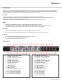
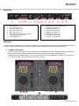
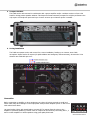
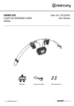
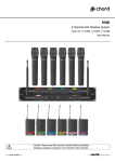
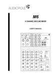
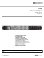
Z44R Multi-purpose Rack Mixer Item ref: 953.020 User Manual 2 balanced microphone inputs Lo-cut rumble filters 3-band EQ per Mic channel Switchable 48V phantom power 2 x A/B selectable stereo line inputs 2-band EQ per Line channel Foot-switchable DSP Reverb or ext. FX 4 stereo zones with selectable line outs Emergency mute contacts Suitable for live vocalist PA Suitable for 4-zone installation Ideal karaoke add-on for DJ Caution: Please read this manual carefully before operating Damage caused by misuse is not covered by the warranty Introduction Thank you for choosing the Adastra Z44R multi-purpose rack mixer. This product has been designed to offer a versatile and wide range of functions to meet many different applications. In order to achieve the best results from this equipment and avoid damage through misuse, please read and follow these instructions and retain for future reference. Warning To prevent the risk of fire or electric shock, do not expose any part of the unit to rain or moisture If liquids are spilled on the surface, stop using immediately, allow unit to dry out and have checked by qualified personnel Avoid impact, extreme pressure or heavy vibration to the unit There are no user serviceable parts inside the mixer – refer all servicing to qualified service personnel Safety Check that the supplied mains lead is in good condition and the supply voltage is correct. Ensure signal leads are of good condition without shorted connections (especially when using phantom power) Do not allow any foreign particles to enter the console through connectors or control apertures Placement Keep out of direct sunlight, away from heat sources and damp or dusty environments When rack-mounting, avoid placing heavy units above the Z44R and ensure all connectors are accessible Cleaning Use a soft cloth with a neutral detergent to clean the casing as required Use a soft brush to clear debris from the control surface Do not use strong solvents for cleaning the unit. Front Panel 1. 2. 3. 4. 5. 6. 7. 8. 9. 10. 11. 12. 13. 14. 15. 16. 48V phantom power LED indicator MIC/LINE 1 LEVEL control MIC/LINE 1 signal and peak LEDs MIC/LINE 1 GAIN control MIC/LINE 2 LEVEL control MIC/LINE 2 signal and peak LEDs MIC/LINE 2 GAIN control LINE 3 LEVEL control LINE 3 peak LED LINE 4 LEVEL control LINE 4 peak LED REVERB TIME parameter control OUT 1 level control & peak LED OUT 2 level control & peak LED OUT 3 level control & peak LED OUT 4 level control & peak LED 17. 18. 19. 20. 21. 22. 23. 24. 25. 26. 27. 28. 29. 30. 31. 32. 33. MIC/LINE 1 combo input MIC/LINE 1 low-cut rumble filter MIC/LINE 1 FX level control MIC/LINE 1 EQ sliders MIC/LINE 2 low-cut rumble filter MIC/LINE 2 FX level control MIC/LINE 2 EQ sliders LINE 3 source select switch LINE 3 EQ sliders LINE 4 source select switch LINE 4 EQ sliders REVERB DEPTH control OUT 1 line selectors OUT 2 line selectors OUT 3 line selectors OUT 4 line selectors Power ON/OFF switch 953.020UK User Manual Rear Panel 1. 2. 3. 4. 5. 6. 7. 8. IEC mains inlet OUT 4 jack outputs L+R OUT 3 RCA outputs L+R OUT 2 RCA outputs L+R OUT 1 RCA outputs L+R MUTE CONTACTS for emergency systems FX LOOP RETURNS jacks L+R FX LOOP SEND jack 9. 10. 11. 12. 13. 14. 15. 16. REVERB or FX LOOP FOOT SWITCH jack LINE 4 B input RCAs L+R LINE 4 A input jacks L+R LINE 3 B input RCAs L+R LINE 3 A input jacks L+R MIC/LINE 2 combo input 48V phantom power switch MIC/LINE 1 rear jack input Application The Z44R can be configured to serve a variety of applications. Deciding upon the particular setup should be the first step in order to ensure all signal leads are connected properly. Some suggested combinations are shown below. 1. DJ Add-on Vocal Mixer For DJs who want the option to host karaoke events, the Z44R offers 2 extra microphone channels with genuine DSP reverb effect and 2 extra switchable line sources (for laptop, CD+G players, MP3 players etc). Adding these extra features takes up just 1U of rack space and can be configured as a sub-mixer into the main DJ console or as the main mixer to offer more stereo outputs… 953.020UK User Manual 2. Compact PA Head The Z44R can be rack-mounted in combination with a power amplifier and/or a wireless receiver to form a PA head for driving passive speaker cabinets. This keeps the format extremely compact for solo/duo performers who only require 2 microphone inputs and up to 2 stereo sources up to whatever power is needed… 3. Zoning Installation The Z44R can operate as the main control for a venue installation, feeding up to 4 stereo zones. Both microphone inputs feed to all outputs (for public address and emergency announcements), whereas the 2 line channels are switchable per zone… Connection Before connecting to amplifier or other equipment, turn down all volume controls to avoid loud noises which may cause damage to other equipment. Always switch amplifier power on last in line with volume levels down. Use good quality 6.3mm jack signal leads to connect OUT 4 outputs from the mixer to the amplifier or powered speaker(s). Further zones or outputs can be served by connecting OUT 1, 2 and 3 to other amplifiers or active speakers using good quality RCA leads. 953.020UK User Manual Connect microphones, DI boxes and other balanced low impedance audio inputs to the MIC/LINE combo inputs using good quality XLR leads. Alternatively, connect high impedance and line level signals to the combo inputs using 6.3mm jack leads. (+ additional rear jack input for MIC/LINE 1). If phantom power is to be used for condenser mics, press “+48V” switch and connect using balanced XLR cables. Connect stereo line level sources to the LINE 3 and LINE 4 channels via the Left + Right Jack or RCA connections on the rear panel. These can be switched, offering a selection of 2 sources for each channel. If the internal DSP reverb effect is to be operated remotely, connect a latching foot switch to the rear panel F/S jack. Alternatively, this can switch the feed from an external unit, which should be connected via the FX LOOP. To do this, connect a jack lead from the SEND to the external effect unit and its left & right outputs to RETURN L+R. In an installation scenario, building regulations may require the sound system to be muted if the fire alarm is triggered. The green MUTE contacts on the rear panel will kill all channels except MIC 1 if the contacts are shorted. This can be patched in to the venue fire alarm panel to kill all music in the event of a fire, leaving the main microphone active for emergency announcements. Operation 1. MIC/LINE channels 1 and 2 Turn all MIC level and LINE LEVEL controls to minimum (2, 5, 8 & 10) Set LO, MID and HI (20 & 23)controls to the centre position and turn FX down (19 & 22) Switch on the power on the right side of the front panel. (33) Check each microphone input, gradually increasing GAIN (4 & 7) until the red Peak LED flashes (3 & 6) and then back off the GAIN until only the green Signal LED lights up Gradually turn up the OUT volume controls (13, 14, 15 & 16) part way Increase the MIC/LINE 1 and 2 LEVEL controls (2 & 5) to the desired level, taking care to avoid distortion or feedback from the microphones. Adjust LO, MID and HI controls to set the desired bass, middle and treble content for each MIC/LINE input If effects are to be used, temporarily unplug the foot switch (if used) and increase the DEPTH control (28) on the front panel. Gradually turn up the FX control(s) (19 22) for the relevant MIC channel(s) and adjust the TIME (12) control to set the desired length of reverb effect. Plug the footswitch back in and use to switch the effect in/out. For some microphones, it can be beneficial to “roll-off” the very low frequencies caused by handling and vibration to the microphone body. If required, press in the Lo-cut Rumble Filter switch (18 & 21) on the microphone channel to reduce this type of noise. 2. Stereo LINE channels 3 and 4 For LINE 3 and 4 channels, check which pair of inputs the signal is plugged into - jack (A) or RCA (B) – and set accordingly via the Source Select switches (24 & 26) on the front panel Press in all of the OUT line selectors (29, 30, 31 & 32) Set HI and LO controls (25 & 27) to the centre position Play the stereo line signal into the relevant channel and increase the LEVEL (8 & 10) control as required Adjust HI and LO controls to set the desired bass and treble content of the stereo line channels 3. Stereo OUTs 1 - 4 Adjust the OUT volume controls (13, 14, 15 & 16) so that the red Peak LEDs do not light constantly Press out any line selectors (29, 30, 31 & 32) for any stereo inputs which are not required to be fed through any output (MIC/LINE inputs are always fed to all outputs) 953.020UK User Manual Specifications Power Supply Mic/Line channel inputs Mic/Line channel controls Line 3 + 4 stereo inputs Line 3 + 4 stereo controls Output connections Output controls FX connections (6.3mm jack) FX controls Indicators (LED) Fire alarm contacts Dimensions Weight 230 – 250Vac 50Hz (IEC) Ch 1 front combo and rear jack, Ch 2 combo (rear) Level, Lo-cut, Gain, FX and Lo/Mid/Hi EQ faders Input A (L+R) 6.3mm jack / Input B (L+R) RCA Level, In A/B and Lo/Hi EQ faders Outputs 1-3 (L+R) RCA, Output 4 (L+R) 6.3mm jack Level, Line 3 on/off, Line 4 on/off Footswitch, Send (defeats onboard reverb), L+R Return Reverb time, Depth (onboard or external level) Power, 48V, Mic/line signal+peak, Line peak, Output peak Modular terminal, make-to-mute all except Mic 1 483 x 44 x 220mm 2.75kg Troubleshooting No power LED on front panel Power LED is on but no other LEDs and no output Power light and output LEDs lighting but no output Output is very loud or distorted Output is working but at very low level Feedback (loud squealing/howling from mics) Ensure mains voltage is correct and connected properly Ensure front panel power switch and mains outlet switch are on Check XLR, jack and RCA leads are OK and connected properly Ensure that low impedance mics. are connected with XLR, not jack Check microphone or line signal is switched on Ensure that any playback devices are not set to “Stop” or “Pause” Ensure GAIN and LEVEL controls are not turned fully down For condenser microphones, check that 48V is on and connected by XLR Check that stereo input selectors are not switched out Check OUT volume controls are not turned fully down Check OUT connections to amplifier or recorder are OK Check amplifier or recorder levels are not turned fully down Check that fire contacts are not shorted out to mute For condenser microphones, check that 48V is on and connected by XLR Check level of amplifier, active speaker or recording device not set too low Check level of input signal is not too high Reduce input channel GAIN, LEVEL and EQ settings Reduce OUT volume control(s) Ensure Hi-Z line level input(s) are not connected via XLR Check FX controls and DEPTH control, reducing if necessary Check input gain level on recorder or recording software Check level of amp, active speaker or recording device not set too high Check level of input signal is not too low Ensure low impedance line or mic signal is connected via XLR, not jack Increase input channel GAIN, LEVEL and EQ settings if turned down Increase OUT volume control(s) Face microphone away from speakers and monitors Reduce channel GAIN, LEVEL and EQ controls Reduce channel FX controls and/or Reverb DEPTH Reduce OUT volume controls and/or amplifier/active speaker volume level Disposal: The “Crossed Wheelie Bin” symbol on the product means that the product is classed as Electrical or Electronic equipment and should not be disposed with other household or commercial waste at the end of its useful life. The goods must be disposed of according to your local council guidelines. Errors and omissions excepted. Copyright© 2014. AVSL Group Ltd. 953.020UK User Manual