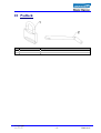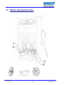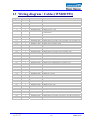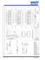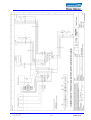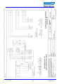
1
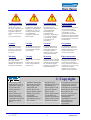
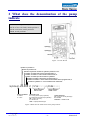
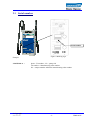
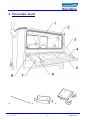
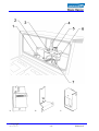
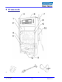
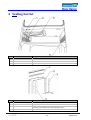
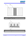
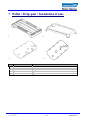
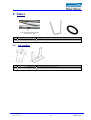
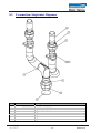
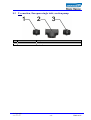
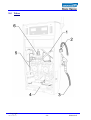
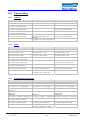
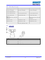
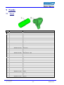
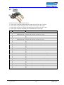
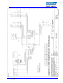
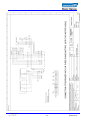
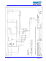
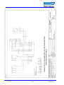
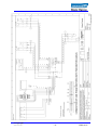
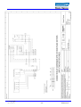
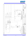
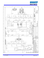
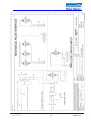
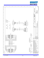
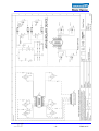
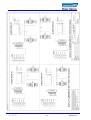
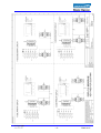
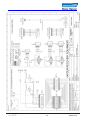
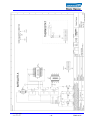
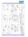
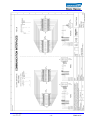
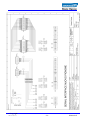
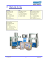
Global Century
(phase 3)
Spare Parts
Global Century
(phase 3)
WM016047 2006-12-05 Rev.02.2
Product Liability
Produktansvar
Produkthaftung
Oтветственнoсть
пoставщика
For the supplier’s product
liability to be valid, no
alterations, additions or the
like may be made to the
equipment without the
supplier’s express permission.
Use only genuine parts
För att en leverantörs
produktansvar skall gälla får
ändringar, kompletteringar
och liknande ej göras i utrustningen utan leverantörens godkännande.
Originalreservdelar skall
alltid användas.
Damit die Produkthaftung
des Lieferanten ihre
Gültigkeit behält, dürfen
ohne ausdrückliche
Genehmigung des
Lieferanten keine
Änderungen, Ergänzungen
o. Ä. an der Ausrüstung
vorgenommen werden.
Verwenden Sie nur
Originalteile.
Для сохранения ответственности нельзя вводить в
оборудование изменения,
дополнения и т.п. без
разрешения поставщика.
Пользуйтесь только оригинальными запасными частями,
выпущенным изготовителем
бензоколонки.
Caution
Varning
Vorsicht
Осторожно
To prevent damage that
might result in electric
shock or fire, disconnect
the main power prior to
any work.
Gör pumpen/enheten strömlös innan Du gör ingrepp i
den. I annat fall föreligger
risk för skada.
Um Beschädigungen zu
vermeiden, die zu einem
elektrischen Schlag oder
Feuer führen können,
unterbrechen Sie vor jeder
Arbeit die Stromzufuhr.
Во избежание поражения
электрическим током или
пожара отключайте напряжение питания перед
началом любых работ.
Warning
Varning
Warnung
Предупреждение
Never run a leaking pump!
Be careful with the
environment and mind the
skidding risk; take care of
leaking fuel immediately.
Använd aldrig en läckande
pump.
Tänk på miljön och halkrisken, sanera utläckt drivmedel snarast.
Lassen Sie nie eine undichte
Zapfsäule laufen! Seien Sie
umweltbewusst und denken
Sie an die Rutschgefahr;
beseitigen Sie austretenden
Kraftstoff umgehend.
Не пользуйтесь колонкой при
наличии утечки топлива!
Охраняйте окружающую
среду, помните об опасности
скольжения: в случае утечки
топлива на дорожное
покрытие возле колонки,
примите меры немедленно.
© Copyright
The contents of this
publication may not be
copied either wholly or
in part without the
consent of Dresser
Wayne AB.
Dresser Wayne AB
reserves the right to
change specifications
contained in the text and
illustrations without
notice.
Innehållet i denna publikation får ej helt eller
delvis kopieras utan
medgivande från
Dresser Wayne AB.
Dresser Wayne AB förbehåller sig rätten att
utan särskilt
meddelande ändra
specifikationer givna i
text och bild.
Der Inhalt dieses
Handbuches darf ohne
die Erlaubnis von
Dresser Wayne weder
ganz noch teilweise
kopiert werden.
Dresser Wayne behält
sich das Recht vor,
textliche oder bildliche
Inhalte ohne besondere
Mitteilung zu ändern.
Не разрешается копировать
полностью или частично
содержание настоящей
публикации без разрешения
фирмы Dresser Wayne АВ.
Dresser Wayne АВ
оставляет за собой право
вносить изменения в
спецификации,
содержащиеся в тексте и
иллюстрациях, без
предварительного
уведомления.
© Copyright
2006-12-05 Rev.02.2
-2-
WM016047
1 Service and maintenance
1.1 Separation of power supply
Separation is done by removing the main fuse of the pump on
the station.
WARNING!
To prevent damage which may result
in electric shock or fire, disconnect the
main power prior to any work.
CAUTION!
Unauthorised personnel may not
execute service and maintenance. This
may cause personal injury or property
damage.
CAUTION!
Avoid the heat element of the
electronics head, risk of skin burn.
WARNING!
Mind the rotating V-belt when the
cover of the hydraulic unit is
removed!
WARNING!
The driving belt may be replaced only
by original belt from Dresser Wayne,
otherwise there is a risk of explosion.
WARNING!
Use your protective equipment.
(Protective mask, gloves etc.)
1.2 Electrostatic discharge (ESD)
Before service/maintenance of a pump discharging must be
done. This is done when you open the covers of the pump
with a key.
If an extensive repair work is to be done, discharge should be
done regularly by touching the key.
WARNING!
The key must have direct contact with
the skin.
NOTE!
Avoid direct contact with electronic
parts of the pump.
© Copyright
2006-12-05 Rev.02.2
-3-
WM016047
2 What does the denomination of the pump
indicate
40 l/min, nozzle position 1, or 2
40-70 or 70 or 130 l/min, nozzle position 1
40-60 or 60 l/min, nozzle position 2
Blend, nozzle position 1
Figure 1 A-side / B-side
Number of products in
Number of products out
Number of hydraulic modules or hydraulic positions in use.
Number of nozzles side A if lane oriented model, or
st
Number of nozzles 1 end if island oriented model, or
Number of nozzles per side if model is symmetric.
Number of nozzles side B if lane oriented model, or
Number of nozzles 2nd end if island oriented model with 2 equipped ends, or
* if model is symmetric => Y1 to Y4 defines both sides/ends.
S(COL/X) XX-XXX P Y1/Y2/Y3/Y4 // Z1/Z2/Z3/Z4
Nozzle definition
side A / end 1
Pump orientation:
I = Island
L = Lane
Nozzle definition
side B / end 2
Technical input:
P = Pump (suction pump hydraulic)
D = Dispenser (remote pump hydraulic)
VR = Vapour recovery
A = Alcohol mix
LPG = Liquid pressurized gas
Nozzle definition:
40 = Flow per minute (example)
B = Blinded
SAT OUT = Satellite outlet
Figure 2 What does the model name of the pump indicate
© Copyright
2006-12-05 Rev.02.2
-4-
WM016047
2.1 Serial number
Serial number
Figure 3 Marking sign
Example
3-94555-001-A =
phase - TO number - No. - pump side
TO number = Manufacturing order number
No. = unique number within the manufacturing order number
© Copyright
2006-12-05 Rev.02.2
-5-
WM016047
© Copyright
2006-12-05 Rev.02.2
-6-
WM016047
3 Contents
Spare Parts hydraulic unit .............................................see document WM011952
Spare Parts vapour recovery unit ..................................see document WM011951
Spare Parts LPG ............................................................see document WM016048
1
Service and maintenance ............................................................................. 3
1.1
1.2
2
Separation of power supply............................................................................................................... 3
Electrostatic discharge (ESD)............................................................................................................ 3
What does the denomination of the pump indicate .................................. 4
2.1
3
4
5
6
7
8
Serial number ..................................................................................................................................... 5
Contents......................................................................................................... 7
Electronic head ............................................................................................. 8
Framework.................................................................................................. 12
Sealing barrier ............................................................................................ 14
Pallet / Drip-pan / foundation frame ........................................................ 16
Tubes............................................................................................................ 17
8.1
8.2
8.3
8.4
8.5
Air venting ........................................................................................................................................ 17
T-connection, Single inlet, Dispenser.............................................................................................. 18
T-conection, European single inlet, suction pump ........................................................................ 19
Tubes ................................................................................................................................................. 20
Vapour tubes..................................................................................................................................... 22
8.5.1
8.5.2
8.5.3
8.5.4
8.5.5
9
Standard....................................................................................................................................................................................22
Fafnir ........................................................................................................................................................................................22
Standard and vaccum gauge.....................................................................................................................................................22
Fafnir and pressure gauge ........................................................................................................................................................23
Vapour outlet............................................................................................................................................................................23
Nozzle........................................................................................................... 24
9.1
9.2
10
11
12
13
14
15
Cover ................................................................................................................................................. 24
Nozzle ................................................................................................................................................ 25
Padlock..................................................................................................... 27
Motor and junction box.......................................................................... 28
Documents................................................................................................ 30
Wiring diagram / Cables (WM011953)................................................. 31
Notes ......................................................................................................... 54
Market & Service .................................................................................... 55
© Copyright
2006-12-05 Rev.02.2
-7-
WM016047
4 Electronic head
8a
8b
8c
© Copyright
2006-12-05 Rev.02.2
-8-
WM016047
1
2
3
4
5
6
7
8a
8b
8c
Part number
Description
WB000674 Edge protector (/m)
CPU board
WM001908-0005 IEC full with CAN-bus
WM001908-0002 IEC low cost
WM004360 Isolated interface board with bypass relay
WM001825 Serial relay board with bypass relay
WM001829 IFSF interface board
WM001827 ATCL interface board
WM015002 Cable, l=545mm
Display board double row
WM010887-0001 1 unit price
Front panel
WM014179-0005 Function keyboard, grey (RAL 7047 gloss 70)
WM014179-0006 Grey (RAL 7047 gloss 70)
WM014179-0007 Function keyboard left, grey (RAL 7047 gloss 70)
WM014179-0008 Function keyboard right, grey (RAL 7047 gloss 70)
WR000307 Glass (aprox. 443x260)
WR000306 Gasket (aprox. 426x195)
Lock
WM001994-0002 Std
WM001994-0003 Individual code (6 lock 2 keys)
WM014075 Latch bezel
WM013613-0001 Washer, lock
WR000292 Support, box-shape, display, functional keyboard
WR000294 Support, box-shape, display right, functional keyboard
WR000296 Support, box-shape, display left, functional keyboard
WR000305 Gasket (aprox. 190x74)
WM003353 Key pad, 12 functional buttons
WM005715-0001 Cable twisted tinned copper strands
WT002156 Hinge, male
WT002157 Hinge, female
© Copyright
2006-12-05 Rev.02.2
-9-
WM016047
7a
7b
7c
© Copyright
2006-12-05 Rev.02.2
- 10 -
WM016047
1
2
3
4
5
6
7a
b
c
Part number
Description
WM008910-0001 Terminal rail
Power supply
WM009807 60W
WM009864 150W
WM014054 Support, U-shape
WM000686 Lamp
WM000689 Lamp holder
WM000428-0003 Heating element 300W
WM002450 Intrinsic safe barrier (ISB)
WM014753 Electromechanical totalizer
WM014060 Support U-shape
WM014654 Support box
© Copyright
2006-12-05 Rev.02.2
- 11 -
WM016047
5 Framework
5b
7a
7b
© Copyright
2006-12-05 Rev.02.2
- 12 -
WM016047
1
Part number
See page 22
WM014080-0001
See page 14
2
3
4
5
5b
6
7a
7b
8
9
10
11
12
*WM016725-0003
*WM016725-0004
*WM016734-0003
*WM016764-0003
*WM016768-0002
*WM016772-0003
*WM016783-0003
*WM016811-0002
*WM016814-0003
*WM016818-0002
WM013995
WM014039
WR000097-0001
WM016557-0001
1094
WR000251-0001
WM014300
WR000471
WR000254
WM014094-0001
WR000252-0001
WR000353-0001
WR000353-0002
WM014079-0001
WR000359
Description
Solenoid valve support
Side panel, grey RAL 7047 (see also page 15)
Support, box-shape, vapour barrier
Column*
*Blinded, grey (RAL 7047)
*Island, grey (RAL 7047)
*Island, high capacity, grey (RAL 7047)
*Lane, grey (RAL 7047)
*Lane, high capacity, grey (RAL 7047)
*Island, mast, grey (RAL 7047)
*Island, mast, high capacity, grey (RAL 7047)
*Lane, mast, high capacity, grey (RAL 7047)
*Lane, mast, grey (RAL 7047)
*Island, LPG, grey (RAL 7047) (LPG see document WM011949)
Support hydraulics
Support L-shape
Cover plate
Plastic fastener, black
Screw MCS 4X12 5.8 FZB
Top panel, grey (RAL 7047)
Chassis electronic head
Mast
Support, hose
Top panel, hydraulics, grey (RAL 7047)
Front panel, white (RAL 9010) (hydraulic door)
Nozzle boot
Auto on
Auto on with flipper
Base, hydraulics, grey (RAL 7047)
Support (vapour recovery unit see document WM011951)
* If the pump is produced 2006 you have the old version of the
vapour barrier support. On these pumps you must change barrier
support (WM015025) and cover plate (WR000097-0001) when you
replace a column.
© Copyright
2006-12-05 Rev.02.2
- 13 -
WM016047
6 Sealing barrier
1
2
3
4
Part number
WM001061
WR000098-0003
WB000267-0001
WR000098-0003
1
2
Part number
See page 12
WM016331
WM015025
3, 4
Description
Cable hanger
Gasket L=374 mm
Edge protector
Gasket L=374 mm
Description
Cover plate
Gasket
Vapour barrier support
(Including gasket WM014880 and WR000098-0003)
WM014880 Gasket
© Copyright
2006-12-05 Rev.02.2
- 14 -
WM016047
1
2
Part number
Description
WM017583 Cover plate vapour barrier (Including gasket WR000098-0001)
WR000098-0001 Gasket L=314 mm
1
2
Part number
Description
WM014080-0001 Side panel, grey RAL 7047 (Including gasket WR000098-0004)
WR000098-0004 Gasket L=411 mm
© Copyright
2006-12-05 Rev.02.2
- 15 -
WM016047
7 Pallet / Drip-pan / foundation frame
1.
2.
3.
4.
1
2
3
4
Part number
Description
WM007472 Pallet L=1160 W=600
WM004774 Foundation frame
Drip pan
WM014169
Suction
WM014171
Dispenser
© Copyright
2006-12-05 Rev.02.2
- 16 -
WM016047
8 Tubes
You will find the tube number
printed on the tube.
1
2
1.
2.
Part number
Description
WM001925 Lock pin for tube fitting
WM003021 O-ring t=4.0, ID=24 (for “double bump”, tube connection)
8.1 Air venting
1.
2.
1
Part number
Description
WM011355 Plug with strainer, for air venting
WM015834 Support L-shape
© Copyright
2006-12-05 Rev.02.2
- 17 -
WM016047
8.2 T-connection, Single inlet, Dispenser
1
2
3
4
5
6
7
Part number
Description
WR000338-0002 T-connection, Single inlet, Dispenser
WR000334-0002
Housing T-connection
WR000337
Coupling, straight union 2 NPT female-female
WR000234-0001
Inlet nipple 1 1/2" , L=44,5
WM003787
Coupling, straight union 1 1/2 NPT female-female
WR000234-0002
Inlet nipple 1 1/2", L=88,9
WR000336
Plug D=75mm
WM003160
Sealant Loxeal 58-11, thread sealant
© Copyright
2006-12-05 Rev.02.2
- 18 -
WM016047
8.3 T-conection, European single inlet, suction pump
1, 3
2
Part number
Description
WM014850 Coupling, straight male
WM014847 T-coupling female
© Copyright
2006-12-05 Rev.02.2
- 19 -
WM016047
8.4 Tubes
© Copyright
2006-12-05 Rev.02.2
- 20 -
WM016047
Part number
1
2
WM014218-0002
WM014222-0002
WM014230-0002
WM014228-0002
WM014244-0002
WM014233-0002
WM014255-0002
WM014258-0002
WM014265-0002
WM014269-0002
WM014273-0002
WM014278-0002
WM014280-0002
WM014282-0002
WM014758
WM014751
WR000341-0002
WR000340-0001
WR000261
WR000350-0002
WR000351
WR000331
3
WM002081-0009
WM002081-0010
WM002078-0010
WM002078-0009
WM002083-0006
WM002095-0005
WM002083-0008
WM002078-0011
WM002081-0011
4
5
6
WM014302-0001
WM014310-0001
WM012266
Description
Tubes fuel delivery
Hydraulic 1 - nozzle 1. side A
Hydraulic 1 - nozzle 2, side B
Hydraulic 1 - nozzle 1. side A, high capacity, island oriented
Hydraulic 1 - nozzle 1. side B, high capacity, island oriented
Hydraulic 1 - nozzle 1, side A, SAT island oriented
Hydraulic 1 - nozzle 1, side B, SAT island oriented
Hydraulic 2 - nozzle 2. side B, high capacity, island oriented
Hydraulic 1 - nozzle 2. side B, high capacity, island oriented
Hydraulic 2 - nozzle 1. side A, high capacity, island oriented
Hydraulic 2 - nozzle 2, side B, high capacity, lane oriented
Hydraulic 1 - nozzle 2, side B, high capacity, lane oriented
Hydraulic 2 - nozzle 1, side A, high capacity, lane oriented
Hydraulic 1 - nozzle 1, side A, high capacity, lane oriented
Hydraulic 1 - hydraulic 2
SAT side A
SAT side B
Housing, outlet 1"
Housing, outlet high capacity
Housing, manifold, high capacity
Housing and sight glass
Housing high capacity and sight glass
Housing vapour recovery
Hose
ID=21 mm, L=4.5 m, black
ID=21 mm, L=4.5 m, black for bio diesel
ID=16 mm, L=4.5 m, black
ID=16 mm, L=4.5 m, black for bio diesel
ID=25 mm, L=4,5 m, black
L=4,5 m, black, vapour recovery
ID=25 mm, L=7.0 m, black (only Greece)
ID=16 mm, L=7.0 m, black (only Greece)
ID=21 mm, L=7.0 m, black (only Greece)
Support vapour recovery unit; See page 12
Vapour recovery unit; See document WM011951
Tubes air venting
Side A
Side B
Connector
© Copyright
2006-12-05 Rev.02.2
- 21 -
WM016047
8.5 Vapour tubes
8.5.1
Standard
Side A and B
WR000361 solenoid valve support
WM015392 tube vapour, nozzle-valve
WM015175
tube vapour, valve-pump side A
WM015176
tube vapour, valve-pump side B
WM015171
tube vapour, pump-outlet side A
WM015174
tube vapour, pump-outlet side B
8.5.2
Side A
WR000361 solenoid valve support
WM015392 tube vapour, nozzle-valve
Side B
WR000361 solenoid valve support
WM015392 tube vapour, nozzle-valve
WM015176
tube vapour, valve-pump side B
WM015174
WM015174
tube vapour, pump-outlet side B
tube vapour, pump-outlet side B
WM015179
tube vapour, valve - pump single side A
Fafnir
Side A and B
Side A
Side B
WM009550 support, L-shape, Fafnir
WM009514
tube vapour, Fafnir - valve
WM009513
tube vapour, nozzle - Fafnir
WM015208
tube vapour, Fafnir - pump side A
WM015197
tube vapour, Fafnir - pump side B
WM015171
tube vapour, pump-outlet side A
WM015174
tube vapour, pump-outlet side B
WM009550 support, L-shape, Fafnir
WM009514
tube vapour, Fafnir - valve
WM009513
tube vapour, nozzle - Fafnir
WM009550 support, L-shape, Fafnir
WM009514
tube vapour, Fafnir - valve
WM009513
tube vapour, nozzle - Fafnir
WM015197
tube vapour, Fafnir - pump side B
WM015174
tube vapour, pump-outlet side B
WM015174
tube vapour, pump-outlet side B
WM015255
tube vapour, Fafnir – pump side A
8.5.3
Standard and vaccum gauge
Side A and B
Side A
WR000361 solenoid valve support
WR000361 solenoid valve support
WM015392 tube vapour, nozzle-valve
WM015392 tube vapour, nozzle-valve
WM015194
WM015194
tube vapour, valve – vacuum gauge
tube vapour, valve – vacuum gauge
WM015208 tube vapour, vacuum gauge pump side A
WM015197 tube vapour, vacuum gauge pump side B
WM015242
WM015242
tube vapour, T-coupling - vacuum gauge tube vapour, T-coupling - vacuum gauge
WM015171
tube vapour, pump-outlet side A
WM015174
WM015174
tube vapour, pump-outlet side B
tube vapour, pump-outlet side B
WM015255
tube vapour, vacuum gauge - pump
Side B
WR000361 solenoid valve support
WM015392 tube vapour, nozzle-valve
WM015194
tube vapour, valve – vacuum gauge
WM015197 tube vapour, vacuum gauge
- pump side B
WM015242
tube vapour, T-coupling - vacuum gauge
WM015174
tube vapour, pump-outlet side B
© Copyright
2006-12-05 Rev.02.2
- 22 -
WM016047
8.5.4
Fafnir and pressure gauge
Side A and B
Side A
WM009550 support, L-shape, Fafnir
WM009550 support, L-shape, Fafnir
WM015242
WM015242
tube vapour, vacuum gauge
tube vapour, vacuum gauge
WM015171
tube vapour, pump-outlet side A
WM015174
WM015174
tube vapour, pump-outlet side B
tube vapour, pump-outlet side B
WM009513
WM009513
tube vapour, nozzle - Fafnir
tube vapour, nozzle - Fafnir
WM015208 tube vapour, vacuum gauge pump side A
WM015197 tube vapour, vacuum gauge pump side B
WB000351-0001 Coupling straight, male WB000351-0001 Coupling straight,
adapter R1/4" x R1/4"
male adapter R1/4" x R1/4"
WB000351-0002 Coupling straight, male WB000351-0002 Coupling straight,
adapter R3/4" x R1/4"
male adapter R3/4" x R1/4"
WM015255
tube vapour, vacuum gauge - pump
8.5.5
Side B
WM009550 support, L-shape, Fafnir
WM015242
tube vapour, vacuum gauge
WM015174
tube vapour, pump-outlet side B
WM009513
tube vapour, nozzle - Fafnir
WM015197 tube vapour, vacuum gauge
- pump side B
WB000351-0001 Coupling straight,
male adapter R1/4" x R1/4"
WB000351-0002 Coupling straight,
male adapter R3/4" x R1/4"
Vapour outlet
4.
1
2
3
4
Part number
WM015035
WB000343-0001
WB000343-0002
WM015019
WM002055
Description
T-coupling male R3/8 female D=10 both ends
Bushing
Bushing plastic
Coupling, straight female 1"X female 1/2" galvanized
Coupling, 90 degree male G 3/8, D=10
© Copyright
2006-12-05 Rev.02.2
- 23 -
WM016047
9 Nozzle
9.1 Cover
Part number
1
WM007104-0001
WM007104-0002
WM007104-0003
WM007104-0004
WM007104-0005
WM007104-0006
WM007104-0007
WM007104-0008
WM007104-0009
WM007545-0001
WM007545-0002
WM007545-0003
WM007545-0004
WM007545-0005
WM007545-0006
WM007545-0007
WM007545-0008
2
WM002013-0006
WM002013-0005
WM002013-0008
WM002013-0009
WM002013-0003
WM002013-0007
WM002013-0004
WM002013-0001
WM002013-0002
WM002337-0005
WM002337-0004
WM002337-0008
WM002337-0002
WM002337-0007
WM002337-0003
WM002337-0006
WM002337-0001
Description
Hose cover
Black CS16
Blude CS16
Red CS16
Green CS16
Yellow CS16
White CS16
Orange CS16
BP dark blue, CS16
BP light blue, CS16
Blue CS21
Yellow CS21
Black CS21
Red CS21
Green CS21
Orange CS21
White CS21
BP dark blue, CS21
Nozzle cover without VR
Black
Blue
Dark blue
Light blue
Green
Light green
Red
White
Yellow
Nozzle cover with VR
Black
Blue
Light blue
Green
Light green
Red
White
Yellow
© Copyright
2006-12-05 Rev.02.2
- 24 -
WM016047
9.2 Nozzle
Nozzles from left to right in picture above:
1. Nozzle spout 31mm. Recommended for high speed flow rates up to 130 lpm.
2. Nozzle spout 24,5mm with drip catch. For flow rates between 40-70 lpm.
3. Nozzle spout 24,5mm. For diesel and leaded petrol with flow rates 40-70 lpm.
4. Nozzle spout 21mm for unleaded petrol. Maximum flow rate 40 lpm.
Part number
U
U
U
WM002128
WM002016-0001
WM002016-0002
WM002016-0003
WM002016-0004
WM002016-0005
WM002016-0006
WM002016-0007
WM002016-0008
WM002016-0009
WM002016-0010
WM002016-0011
WM002016-0012
WM002016-0013
WM002016-0037
WM002016-0038
WM002016-0039
WM002016-0040
WM002016-0041
WM002016-0043
WM002016-0044
WM002016-0045
WM002016-0046
WM002016-0046
WM002016-0047
WM002016-0048
WM002016-0049
WM002016-0050
WM012773-0001
Description
With cover, without VR
ZVA 25, 8D, black
19mm, 8D, spout ID=19/OD=24.5, yellow
19mm, 8D, spout ID=19/OD=24.5, black
19mm, 8D, spout ID=19/OD=24.5, white
19mm, 8D, spout ID=19/OD=24.5, red
19mm, 8D, spout ID=19/OD=24.5, green
19mm, 8D, spout ID=19/OD=24.5, blue
19mm, 8D, spout ID=16/OD=21, black
19mm, 8D, spout ID=16/OD=21, blue
19mm, 8D, spout ID=16/OD=21, green
19mm, 8D, spout ID=16/OD=21, red
19mm, 8D, spout ID=16/OD=21, white
19mm, 8D, spout ID=16/OD=21, yellow
19mm, 8D, spout ID=21/OD=25, black, D.catch+stop
19mm, 8D, spout ID=21/OD=25, black, drip catcher
19mm, 8D, spout OD=21, BP dark blue, comfi grip
19mm, 8D, spout OD=21, BP dark blue
19mm, 8D, spout OD=25, BP dark blue, comfi grip
19mm, 8D, spout OD=25, BP dark blue
19mm, 8D, spout OD=25, BP dark blue,drip catcher
19mm, 8D, spout OD=21, BP light blue, comfi grip
19mm, 8D, spout OD=25, BP light blue, comfi grip
19mm, 8D, spout OD=21, blue, ethanol
19mm, 8D, spout ID=16/OD=21, blue, ethanol
19mm, 8D, spout ID=16/OD=21, light green
19mm, 8D, spout ID=19/OD=25, light green
19 mm, 8D, spout ID=19/OD=21, BP light blue
19 mm, 8D, spout ID=19/OD=25, BP light blue
19mm, 8D, OD=25, BP dark blue, comfi g, drip cat
© Copyright
2006-12-05 Rev.02.2
- 25 -
WM016047
Part number
U
U
U
U
2
WM002123-0001
WM002123-0002
WM002123-0003
WM002123-0004
WM002123-0005
WM002123-0006
WM002123-0007
WM002123-0008
WM002123-0009
WM002123-0010
WM002123-0011
WM002123-0012
WM002123-0017
WM002123-0026
WM002123-0027
WM002123-0029
WM002123-0030
WM002009
WM005331
WM000631-0001
WM012315-0001
WM012315-0002
WM012315-0003
WM012315-0004
WM012315-0005
WM012315-0006
WM012315-0007
WM012317-0001
WM012317-0002
WM012317-0003
WM012317-0004
WM012317-0005
WM012182-0001
WM012182-0002
WM012300-0001
Description
With cover, with VR
8D, spout OD=25, yellow
8D, spout OD=25, black
8D, spout OD=25, white
8D, spout OD=25, red
8D, spout OD=25, green
8D, spout OD=25, blue
8D, spout OD=21, black
8D, spout OD=21, blue
8D, spout OD=21, green
8D, spout OD=21, red
8D, spout OD=21, white
8D, spout OD=21, yellow
8, spout OD=21, green
8D, spout OD=21, BP light blue, comfi grip
8D, spout OD=25, BP light blue, comfi grip
8D, spout OD=25, light green
8D, spout OD=21, light green
Handle 8D
Nozzle locking mechanism
Self tapping screw, Torx, CSK head, type C ST 2,9X9,5
Splash guard
ID=24, OD=82, BP light blue (NL)
ID=24, OD=82, green
ID=24, OD=82, green
ID=24, OD=82, green (UK)
ID=24, OD=82, blue
ID=24, OD=82, red
ID=24, OD=82, yellow
ID=26, OD=92, BP light blue (AT)
ID=26, OD=92, BP dark blue (AT)
ID=26, OD=92, green
ID=26, OD=92, black
ID=26, OD=92, blue
Comfi grip
BP light blue
BP dark blue
VR, BP light blue
2.
© Copyright
2006-12-05 Rev.02.2
- 26 -
WM016047
10 Padlock
1
2
Part number
Description
WM003189 Padlock
WM002518-0001 Pin
© Copyright
2006-12-05 Rev.02.2
- 27 -
WM016047
11 Motor and junction box
5.
6.
7.
© Copyright
2006-12-05 Rev.02.2
- 28 -
WM016047
1
2
3
4
5
6
7
Part number
Description
WM014495 Support V-shape
Junction box
WM001736
Data
WM001740
Dispenser
WM003288
3 phase, 230V, UPL dispenser
WM003290
Data SAT MPI
WM003292
UPS 230V
WM003294
CODAB
WM008200-0001
3 phase-230V, 24V, date with MC
WM008200-0002
3 phase-230V, 24V, date without MC (shown in figure)
WM008773-0001
3 phase-230V, 24V, date, dispenser with MC
WM008773-0001
3 phase-230V, 24V, date, dispenser without MC
V-belt
Only antistatic V-belts may be used
WM003054
Z-profile SPZ 787
WM003055
Z-profile SPZ 800
Motor
WM014976-0003
3-phase 0.75kW 400V 50Hz
WM014978-0003
3-phase 1.1kW 400V 50Hz
WM004303 Pulley for Z-belt for the pump unit (included spacer)
WM001667 Key, Woodruff D=19, T=4.75
WB000341-0001 Nut, 5/8" UNF JAM-nut
WM000446 O-ring T=3.0, ID=64.5
WM001452 Fan plastic
© Copyright
2006-12-05 Rev.02.2
- 29 -
WM016047
12 Documents
Part number
WM014499
WM014500
WM014502
WM014503
WM014504
WM014501
WM014505
WM014506
WM014507
WM014508
WM014509
WM014510
WM014511
WM014512
WM014513
WM014514
461450
461251
461383
WM011951
WM011952
Description
User’s Manual (with installation drawings)
CZ
DE
ES
FI
FR
GB (English)
IT
NL
PL
PT
RO
RU
SE
SI
UA
YU
Painting Instructions
Spare part list SAT II
A/L test and Maintenance, Vapour recovery pump (8014-5.0) from
ASF Thomas
Spare Parts vapour recovery unit
Spare Parts hydraulic unit
© Copyright
2006-12-05 Rev.02.2
- 30 -
WM016047
13 Wiring diagram / Cables (WM011953)
Sequence
Quantity
Item Number
*1
*2
*3
*4
*5
*6
*7
*8
1
1
1
1
1
1
1
1
WM003722-0002
WM010634-0001
WM011045-0001
WM010637-0001
WM003752-0002
WM003863-0001
WM004089-0001
WM008689-0001
*9
* 10
* 11
* 12
* 13
* 14
* 15
* 16
* 17
* 18
* 19
* 20
* 21
* 22
* 23
* 24
* 25
* 26
* 27
* 28
* 29
* 30
* 31
* 32
* 33
* 34
* 35
* 36
* 37
* 38
* 39
* 40
* 41
* 42
* 43
* 44
* 45
* 46
* 47
* 48
* 49
1
1
1
1
1
1
1
1
1
1
1
1
1
1
1
1
1
1
1
1
1
1
1
1
1
1
1
1
1
1
1
1
1
1
1
1
1
1
1
1
1
WM008599-0001
WM003892-0003
WM008599-0004
WM013914-0001
WM003946-0001
WM003892-0001
WM008117-0001
WM003734-0001
WM004096-0002
WM008592-0002
WM003927-0001
WM004764-0001
WM003892-0005
WM003933-0001
WM003731-0003
WM003861-0002
WM010538-0002
WM006840-0001
WM003861-0001
WM003758-0001
WM006838-0001
WM003760-0004
WM003760-0003
WM011988-0001
WM004085-0002
WM006836-0001
WM003755-0001
WM004105-0001
WM003980-0001
WM004126-0001
WM006822-0001
WM008566-0001
WM003736-0001
WM010637-0002
WM003984-0001
WM010089-0001
WM006828-0001
WM003892-0002
WM014641-0001
WM009592-0001
WM004094-0002
Title
CABLE MULTI 1x0.5 RD L=130,130,30; 1x0.5 BK L=130,130,30
CABLE 2x0.5 ZONE L=250
CABLE 2x0.5 ZONE L=200
CABLE 4x0.5 ZONE L=250
CABLE 4x0.34 ZONE SC Eexi L=2500
CABLE SINGLE WIRE 1x0.75 RD L=100
CABLE 4x0.25 L=1100
THERMOSTAT WITH CABLE 2x0.75 BN, 1x0.75 BU
L=400/650/100
CABLE SINGLE WIRE 1x0.75 BU L=300
CABLE SINGLE WIRE 1x0.75 BN L=450
CABLE SINGLE WIRE 1x0.75 BU L=700
CABLE SINGLE WIRE 1x0.5 RD L=300
CABLE MULTI 1x0.5 BK L=300, 1x0.5 BK L=50, 1x0.5 BK L=50
CABLE SINGLE WIRE 1x0.75 BN L=150
CABLE 12G0.75 ZONE L=2500
CABLE MULTI 1x0.5 RD L=600, 1x0.5 BK L=600
CABLE SINGLE WIRE 1x1.5 BU L=300
CABLE SINGLE WIRE 1x1.5 BN L=300
CABLE SINGLE WIRE 1x0.75 GN/YE L=300
CABLE MULTI 1x0.5 RD L=250, 1x0.5 BK L=250
CABLE SINGLE WIRE 1x0.75 BN L=700
CABLE SINGLE WIRE 1x0.75 GN/YE L=150
CABLE MULTI 1x0.5 RD L=900, 1x0.5 BK L=900
CABLE FLAT 16-POSITION 1.27-PITCH L=400
ON/OFF SWITCH WITH CABLE 2x0.75 BN, 2x0.75 BU L=400
CABLE 2x0.5 L=600
CABLE FLAT 16-POSITION 1.27-PITCH L=150
CABLE 4x0.34 L=1100
CABLE 8x0.5 L=600
CABLE FLAT 10-POSITION 1.27-PITCH L=1400
CABLE FLAT 10-POSITION 1.27-PITCH L=900
CABLE MULTI 2x0.34 L=850, 2x0.34 L=850
CABLE 2x0.34 L=850
CABLE 8x0.5 L=900
CABLE 4x0.5 ZONE L=2700
CABLE SINGLE WIRE 1x0.75 BK L=75
CABLE 2x0.34 L=300
CABLE SINGLE WIRE 1x10 GN/YE L=10000
CABLE HIGH VOLTAGE 5G1.5 ZONE L=2500
CABLE HIGH VOLTAGE 4G1.5 ZONE L=2450
CABLE 4x0.34 L=200
CABLE 4x0.5 ZONE L=2500
CABLE 4x0.5 ZONE SC L=10000
CABLE 7G0.75 ZONE L=2500
CABLE HIGH VOLTAGE 3G1.5 ZONE L=2500
CABLE SINGLE WIRE 1x0.75 BN L=300
CABLE MULTI 1x1.5 BK L=250,1x1.5 GN/YE L=250
CABLE MULTI 1x0.5 RD L=350,350,30, 1x0.5 BK L=350,350,30
CABLE 4x0.5 ZONE L=3300
© Copyright
2006-12-05 Rev.02.2
- 31 -
WM016047
© Copyright
2006-12-05 Rev.02.2
- 32 -
WM016047
© Copyright
2006-12-05 Rev.02.2
- 33 -
WM016047
© Copyright
2006-12-05 Rev.02.2
- 34 -
WM016047
© Copyright
2006-12-05 Rev.02.2
- 35 -
WM016047
© Copyright
2006-12-05 Rev.02.2
- 36 -
WM016047
© Copyright
2006-12-05 Rev.02.2
- 37 -
WM016047
© Copyright
2006-12-05 Rev.02.2
- 38 -
WM016047
© Copyright
2006-12-05 Rev.02.2
- 39 -
WM016047
© Copyright
2006-12-05 Rev.02.2
- 40 -
WM016047
© Copyright
2006-12-05 Rev.02.2
- 41 -
WM016047
© Copyright
2006-12-05 Rev.02.2
- 42 -
WM016047
© Copyright
2006-12-05 Rev.02.2
- 43 -
WM016047
© Copyright
2006-12-05 Rev.02.2
- 44 -
WM016047
© Copyright
2006-12-05 Rev.02.2
- 45 -
WM016047
© Copyright
2006-12-05 Rev.02.2
- 46 -
WM016047
© Copyright
2006-12-05 Rev.02.2
- 47 -
WM016047
© Copyright
2006-12-05 Rev.02.2
- 48 -
WM016047
© Copyright
2006-12-05 Rev.02.2
- 49 -
WM016047
© Copyright
2006-12-05 Rev.02.2
- 50 -
WM016047
© Copyright
2006-12-05 Rev.02.2
- 51 -
WM016047
© Copyright
2006-12-05 Rev.02.2
- 52 -
WM016047
© Copyright
2006-12-05 Rev.02.2
- 53 -
WM016047
14 Notes
_________________________________________________________________________________________
_________________________________________________________________________________________
_________________________________________________________________________________________
_________________________________________________________________________________________
_________________________________________________________________________________________
_________________________________________________________________________________________
_________________________________________________________________________________________
_________________________________________________________________________________________
_________________________________________________________________________________________
_________________________________________________________________________________________
_________________________________________________________________________________________
_________________________________________________________________________________________
_________________________________________________________________________________________
_________________________________________________________________________________________
_________________________________________________________________________________________
_________________________________________________________________________________________
_________________________________________________________________________________________
_________________________________________________________________________________________
_________________________________________________________________________________________
_________________________________________________________________________________________
_________________________________________________________________________________________
_________________________________________________________________________________________
_________________________________________________________________________________________
_________________________________________________________________________________________
_________________________________________________________________________________________
_________________________________________________________________________________________
© Copyright
2006-12-05 Rev.02.2
- 54 -
WM016047
15 Market & Service
Sweden
Italy
UK
Dresser Wayne AB
Dresser Wayne Pignone Deg Italia S.p.a.
Dresser Wayne, DI UK Ltd
Limhamnsvägen 109
Box 30049
SE-200 61 Malmö
Tel
Fax
+ 46 40-36 05 00
+ 46 40-15 03 81
Via Giovanni Piantanida, 12
50127 FIRENZE (FI), Italy
Butlerfield Industrial Estate,
Bonnyrigg, Midlothian,
Scotland. EH19 3JQ
Tel +39 055 3039 200
Fax +39 055 3039 007
Tel.
Fax
www.wayne.se
E-mail: [email protected]
+44 (0)1875 402141
+44 (0)1875 400010
www.wayneuk.com
E-mail: [email protected]
Germany
Wayne Germany
Dresser Europe GmbH
Grimsehlstr. 44
37574 Einbeck
Tel.
Fax
+49 (0) 5561 / 794 -0
+49 (0) 5561 / 794 -187
www.wayne-europe.com
E-Mail: [email protected]
© Copyright
2006-12-05 Rev.02.2
- 55 -
WM016047
More than a century of experience
Über 100 Jahre Erfahrung
Mer än 100 års erfarenhet
Более, чем столетний опыт работы
Wayne Dresser develops,
manufactures and markets
complete operative systems
for fuel handling at service
stations. Everything from
development and design to
efficient production and
assembly of components is
pursued under one roof.
The operations of Wayne
Dresser comprise four
interacting parts:
•
•
Equipment such as
petrol pumps, payment
terminals, point-of-sale
terminals and service
station operative
systems.
Software for recording
and for internal
communication at the
station, as well as
between the station and
the oil company, banks
and credit institutes.
•
Project design with
overall responsibility to
the customer.
•
Field service, technical
support and supply of
spare parts.
Wayne Dresser makes it
easier for the motorist to fill
up and make his motoring
purchases, while effectively
meeting the needs of the
service station owner for
operating supervision and
for conforming to the
demands of the authorities
on measuring accuracy,
minimising pollution and
ensuring safety.
Wayne Dresser entwickelt,
produziert und vermarktet
komplette funktionierende
Systeme für die Abgabe von
Kraftstoffen an Tankstellen.. Von
der Entwicklung über das Design
bis zur Herstellung und
Installation liefern wir alles aus
einer Hand.
Wayne Dresser utvecklar,
tillverkar och marknadsför
kompletta operativa system
för drivmedelshantering på
servicestationer. Under ett
och samma tak ryms allt från
utveckling och konstruktion
till rationell tillverkning och
sammansättning av komponenter.
Wayne Dresser разрабатывает,
производит и продает
совершенные оперативные
системы для торговли топлива на
станциях обслуживания. Все
начиная от разработок и
конструкции до эффективного
производства и сборки
компонентов происходит в
пределах одного предприятия.
Verksamheten omfattar
fyra samverkande delar:
Действия Wayne Dresser
включают четыре
взаимосвязанных направления:
Die Niederlassungen von
Wayne Dresser umfassen vier
ineinander greifende Bereiche:
•
Ausrüstungen wie
Zapfsäulen, Zahlterminals,
Kassenterminals und
Tankstellensysteme
•
Software für Registrierung
und Kommunikation auf
der Tankstelle u. zwischen
Station und
Mineralölfirma sowie
Banken und
Kreditinstituten.
•
•
Projektgestaltung mit
umfassender
Verantwortlichkeit dem
Kunden gegenüber.
Service, technische Unterstützung und Lieferung
von Ersatzteilen.
Wayne Dresser erleichtert dem
Fahrer die Betankung und damit
verbundene Einkäufe,
unterstützt gleichzeitig den
Stationär bei der übersichtlichen
Führung seines Betriebes unter
Berücksichtigung der
behördlichen Vorschriften
hinsichtlich Messgenauigkeit,
Umwelt- und
Sicherheitsauflagen.
Headquarters
3814 Jarrett Way
Austin, TX 78728
Phone: +1 512.388.8311
Fax: +1 512.388.8302
www.wayne.com
Wayne Pignone
Deg Italia S.p.a.
Via Giovanni Piantanida, 12
50127 Florence ,Italy
Phone +39 055 3039 200
Fax +39 055 3039 007
•
Оборудование, например,
топливораздаточные
колонки, платежные
терминалы, терминалы
точек продажи и системы
управления АЗС.
•
Projektering med
totalansvar gentemot
uppdragsgivaren.
Программное обеспечение
для регистрации и для
внутренней связи на АЗС, а
также между АЗС и
нефтяной компанией,
банками и институциями
кредитов.
•
Service på fältet,
teknisk support och
reservdelsförsörjning.
Проектирование с полной
ответственностью к
клиенту.
•
Обслуживание на местах,
техническая поддержка и
поставка запасных частей.
•
Utrustning som
bensinpumpar, betalterminaler,
butiksterminaler och
stationsdatorer.
•
Programvara för
registrering och kommunikation internt på
stationen samt mellan
stationen och oljebolaget, banker och
kreditinstitut.
•
•
Wayne Dresser gör det
lättare för bilisten att tanka
och handla. Samtidigt
tillgodoses stationsägarens
krav på en effektiv driftskontroll och myndighetskraven på mätnoggrannhet,
miljövänlighet och
driftssäkerhet.
Wayne Brazil
Estrada do Timbo
126-Bonsucesso
Rio de Janeiro, Brazil
Phone: +55-21-2598-7711
Fax: +55-21-2598-7860
Wayne Dresser упрощает
процесс заправки и
приобретения покупок при
эффективном согласовании
потребностей владельца АЗС
для оперативного управления и
для соблюдения требований
государственных и
метрологических служб, а
также уменьшения загрязнения
окружающей среды и
обеспечения безопасности.
Wayne China
1221 Dong Lu Road
Pudong, Shanghai 200135
China
Phone: +8 21-5899-3976
Fax: +8 21-5899-0974
Wayne Sweden
Limhamnsvägen 109
Box 30049
SE-200 61 Malmo Sweden
Phone: +46 40 360500
Fax: +46 40150381
www.wayne.se