Transcript
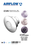
9041549
Issue 3
06/10
Domestic DC Fans – iCON SELV/iCON eco S
Installation and Operating Guide
The iCON SELV transformer unit has a thermal protection device internally fitted, and an
external 3A fuse is required for each transformer unit; therefore no internal fuse is fitted to
the fan unit.
• The output cable to the fan, typically is 1.5mm2 for a 5m cable run, can be routed into the
transformer unit via the positions E (bottom), H (side) or I (side); whichever is most
convenient.
The iCON eco S power supply has resettable over current and short circuit protection. An
external 3Amp fuse is still required with each power supply. The eco S (power supply) has
a Led indicator to show that the unit is switched on and functioning correctly.
Note: Never cover the transformer unit with thermal insulation or other materials.
The transformer requires a 230V 50Hz single phase supply and has a 12V dc output for
the iCON eco SELV fan. Class II equipment. BS EN 60417.
GB
iCON eco S Power Supply Unit
Brown
Live
Brown
+12V
Part Number: 9041336
Power Supply Unit
Airflow Developments LTD, High Wycombe, HP12 3QP. UK.
Email: [email protected]
Web: airflow.com
Grey
Neutral
230V Mains
input
Brown
iCON eco15S
iCON 15 SELV
iCON 30 SELV
Note: Switches for fans shall be selected and sited in accordance with BS7161:2008
Mechanical Installation
iCON SELV (Safety Extra Low Voltage) and iCON eco S fans are available in 2 model
sizes and can be fitted to a wall or ceiling. Each fan requires a suitable size hole through
the wall or ceiling which connects into a duct venting to the outside. The external opening
should be covered by a suitable external grill, available separately from Airflow
Developments Ltd..
Transformer
The iCON SELV and iCON eco S range can be
recessed in a wall or ceiling. A mounting skirt is
provided for surface mounting the iCON 30
SELV and iCON eco30S.
The iCON SELV transformer unit should not be fitted in Zone 0, 1 or 2 and must be sited
out of reach of anyone using the bath, shower or sink. The units are usually installed
outside the room or in an accessible roof space with adequate circulation of air around the
transformer unit to avoid overheating.
iCON eco15S -100mm Axial Fan with maximum capacity of 21.9 l/sec.
iCON eco30S -100mm Mixed Flow Fan with maximum capacity of 34.25 l/sec
iCON 15 SELV -100mm Axial Fan with maximum capacity of 19.5 l/sec.
iCON 30S SELV -100mm Mixed Flow Fan with maximum capacity of 31 l/sec
The maximum distance between the transformer and fan units, when using 1.5mm2 cable
is 5m.
Do not place the fan near direct heat sources, e.g. radiant heaters, or where temperatures
can exceed 40°C (104°F).
• Unscrew 2 retaining screws and
remove the cover.
• Using the transformer base, spot
F
H
through the fixing holes (A, B or C).
Note: Choice of fixing positions (A, B
or C) depends on the location.
D
E
• Ceiling or wall mounting: Drill to
B C
A
accept plastic wall plugs and screw
the transformer unit to the support
M
A
F
using the 2 mounting screws (Pan
I
J
A
N
K
N
S
head, self tapping: 4mm x 32 long)
supplied in fixing kit.
G
• Roof space: Screw the transformer
unit to the support using the 2
mounting screws (Pan head, self
tapping: 4mm x 32 long) supplied in
the fixing kit.
• The 230V mains cable can be routed into the transformer unit via the knock out positions
D (bottom), G (side) or F (side); whichever is most convenient.
Page 2 of 8
Page 3 of 8
IC2
C1
+
D3
C3
D2
+
D4
PLYWOOD
MOUNTING
SKIRT
T
+V
Page4 of 8
iCON SELV/iCON eco S control module with external switching.
Applicable to units installed and used in the United Kingdom. Airflow guarantees the iCON
SELV/iCON eco S fan units and SELV/eco S modules for 3 YEARS from date of purchase
against faulty material or workmanship. Warranty only covers the fan, not the reinstallation
of this if required.
A
L
N
N
L
LS
L
N
LS
RCD
T
0v
+12v
3 AMP
SWITCHED FUSE TRANSFORMER / POWER
SUPPLY
iCON SELV/iCON eco S control module with no external switching.
B
PLYWOOD
When recessing fans in the ceiling, a plywood support (min 18mm thick) should be
mounted between the ceiling joists. Fans should not be fitted to unsupported plaster board.
When surface mounting the iCON 30 SELV/iCON eco30S the mounting skirt should be
used.
L
RCD
3 AMP
SWITCHED FUSE
LS
T
N
0v
L
+12v
TRANSFORMER / POWER
SUPPLY
Refer to instructions supplied with (optional) modules for further information.
Electrical Installation
Maintenance
All electrical installation to be carried out by an approved electrician in accordance with
Part “P” U.K. Building Regulations and to the latest IEEE standards, or the appropriate
regulations in the country of installation.
The iCON SELV/iCON eco S transformer unit requires a 230V 50Hz supply, it is double
insulated so does not require an earth.
The iCON SELV/iCON eco S fan requires a 12V dc supply via the transformer.
SAFETY FIRST: ALWAYS ISOLATE THE FAN UNIT FROM THE POWER SUPPLY
BEFORE REMOVING THE COVER.
N
L
RCD
3 AMP
SWITCHED FUSE
LS
T
N
0v
L
+12v
TRANSFORMER / POWER
SUPPLY
In the event of any defective parts being found, Airflow Developments Ltd reserve the right
to repair or at our discretion replace without charge provided that the unit:
1. Has been installed and used in accordance with the fitting and wiring instructions
supplied with each unit.
2. Has not been connected to an unsuitable electrical supply.
3. Has not been subjected to misuse, neglect or damage.
4. Has not been modified or repaired by any person not authorised by Airflow
Developments Ltd
5. Has been installed in accordance with latest Building Regulations and IEEE wiring
regulations.
Airflow Developments shall not be liable for any loss, injury or other consequential
damage, in the event of a failure of the equipment or arising from, or in connection with,
the equipment excepting only that nothing in this condition shall be construed as to
exclude or restrict liability for negligence.
This warranty does not in any way affect any statutory or other consumer rights.
Warranty only covers the fan, not the reinstallation of this if required.
When installed according to these instructions the iCON SELV/iCON eco S fans are
completely safe.
The materials used do not constitute a hazard. The module covers are made of a flame
retardant material.
The iCON 15 SELV and iCON eco15S requires a 110mm diameter hole through the
ceiling. The fan to be fixed, with the screws provided, through the plaster board into the
support.
The iCON 30 SELV and iCON eco30S requires a 160mm diameter hole through the
ceiling. The fan to be fixed, with the screws provided, through the plaster board into the
support.
N
The iCON 30 SELV/iCON eco30S requires a 110mm diameter hole through the ceiling.
The surface mounted skirt to be fixed, with the screws provided, through the plaster board
into the support. The fan is then fitted into the skirt.
iCON SELV/iCON eco S wiring with no control module fitted.
UNDO THE RETAINING
SCREW AT THE BOTTOM
EDGE OF COVER USING A
SCREWDRIVER.
Warranty
When surface mounting the iCON 30 SELV and iCON eco30S the supplied mounting skirt
should be used.
The iCON 30 SELV and iCON eco30S requires a 110mm diameter hole through the wall
lined with a 100mm id duct.
CEILING
The front cover of the iCON SELV and
iCON eco S fan has a bayonet type fitting.
To remove, undo the retaining screw at
the bottom edge of the cover using a
screwdriver, then rotate the cover a few
degrees anticlockwise and remove. To
refit, reverse the above procedure.
0V
C2
Optional Modules for iCON SELV/iCON eco S
JOIST
Recessing iCON SELV/iCON eco S Fans in Ceiling
Front Cover Removal
IC1
Surface Mounting iCON SELV/iCON eco S Fans on Wall
To avoid reduced flow, an elbow plenum should
be used for all installations which contain
bending of ducting.
R2
L
DUCT
Ensure free running of the fan impeller and that
flexible duct connections are not over tightened
to the fan outlet spigot.
D6
CON2
N
POSSIBLE CABLE
ROUTING
CONDENSATION
TRAP
D8
R1
Ls
Surface Mounting iCON SELV/iCON eco S Fans on Ceiling
To avoid the backflow of condensation into the
fan in ceiling installation it is good practice to fit
a CONDENSATION TRAP to the outlet duct of
the fan.
D7
CON1
C1
The iCON SELV and iCON eco S fans have IP X4 rated housings, they are doubleinsulated and are suitable for fitting in Zone 1 or 2 of bathrooms, toilets, kitchens, utility
rooms and inside shower cubicles as defined in Section 701 BS7161:2008 (IEEE Wiring
Regulations, Seventeenth Edition ). The iCON SELV and iCON eco S also complies with
the Building Regulations, Approved Document F. The transformer unit, supplied with the
fan, must be fitted outside of Zones 0, 1 and 2. It is usually installed outside the room.
The iCON 15 SELV and iCON eco15S requires a 110mm diameter hole through the wall
lined with a 100mm id (internal diameter) duct.
The iCON 30 SELV and iCON eco30S requires a 110mm diameter hole through the wall,
counter bored 160mm diameter to a depth of 75mm. The 110mm hole should be lined with
a 100mm id duct.
CEILING
Black
Switched
+12V
Installation, Maintenance and Use
D5
JOIST
Grey
Black
Fan Unit
D1
DUCT
Brown
ALWAYS ISOLATE THE TRANSFORMER AND FAN UNITS FROM THE POWER
SUPPLY BEFORE REMOVING THE COVER.
Airflow Developments Ltd
POSSIBLE CABLE
ROUTING
Grey
-0V
12v Output
to fan
12v
0v
T
Airflow 12v iCON SELV and iCON eco S Domestic Fan
The iCON SELV and iCON eco S range can be used as a simple extract fan powered via
the SELV transformer unit, and connected to either a remote switch, or can be fitted with
an internal control module, supplied to give a range of control options including timer,
humidity, motion sensor, pull cord, trickle speed or combinations of these functions.
Optional modules are available separately and can be fitted at the time of installation or
retrofitted.
Recessing iCON SELV/iCON eco S Fans in Wall
L
N
Ls
The iCON eco S power supply unit does not require dismantling and should be installed by
a qualified electrician to BS7161:2008 (IEEE wiring standards 17th Edition). The maximum
length of wire between the power supply and the fan should not exceed 5m using 1.5mm2
wire.
Model
Model
Model
Model
12V SELV Base Models:
iCON eco15S – 72683701
iCON eco30S – 72683801
iCON 15 Selv – 72591801
iCON 30 Selv– 72591901
Black
Switched
Live
Grey
Black
All electrical installation to be carried out by an approved electrician in accordance with
Part “P” U.K. Building Regulations and to the latest IEEE standards, or the appropriate
regulations in the country of installation.
Airflow iCON SELV and iCON eco S Model Options
eco
Input: 100-240v AC 50~60Hz
Output: 12v DC regulated
Max Ambient Temperature: 40°C
IP55
Cleaning
• The external housing of the fan can be wiped with a damp cloth. Do not use household
cleaners containing abrasives.
• Cleaning of the internal parts such as the impeller should be carried out using a soft
brush.
Note: Always ensure that the fan unit is isolated from the power supply before inserting the
brush into the impeller duct.
• Never clean any parts of the fan assembly by immersing in water or using a dishwasher.
Manufacturer
Czexh Republic
Germany
AIRFLOW DEVELOPMENTS Ltd
Aidelle House, Lancaster Road
Cressex Business Park
High Wycombe
Buckinghamshire
HP12 3QP
United Kingdom
AIRFLOW LUFTTECHNIK GmbH
o.s. Praha
Hostýnská 520
108 00 Praha 10
Malešice
Czech Republic
AIRFLOW LUFTTECHNIK GmbH
Postfach 1208
D-53349 Rheinbach
Germany
Tel:
Fax:
Email:
Web:
+44 (0) 1494 525252
+44 (0) 1494 461073
[email protected]
airflow.com
Tel:
Fax:
Email:
Web:
+42 (0) 2 7477 2230
+42 (0) 2 7477 2370
[email protected]
airflow.cz
Tel:
Fax:
Email:
Web:
+49 (0) 222 69205 0
+49 (0) 222 69205 11
[email protected]
airflow.de
AIRFLOW DEVELOPMENTS Limited reserve the right in the interest of continuous development to alter any or all specifications without prior notice.
Page 5 of 8
Page 6 of 8
Page 7 of 8
Page 8 of 8