1
Cat. No. Z182-E1-02
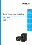
E5AR
E5ER
Digital Controller
USER MANUAL
Introduction
OMRON products are manufactured for use according to proper procedures by a qualified operator and
only for the purposes described in this manual.
This manual describes the functions, performance, and application methods needed for optimum use of
the E5AR/E5ER Digital Controllers.
Please observe the following items when using the E5AR/E5ER Digital Controllers.
• This product is designed for use by qualified personnel with a knowledge of electrical systems.
• Read this manual carefully and make sure you understand it well to ensure that you are using the E5AR/
E5ER Digital Controllers correctly.
• Keep this manual in a safe location so that it is available for reference when required.
Precaution in using the product
Before using the Controller under the following conditions, make sure that the ratings and performance
characteristics of the Controller are sufficient for the systems, machines, and equipment, and be sure to
provide the systems, machines, and equipment with double safety mechanisms, and also consult your
OMRON representative.
• Using the Controller under conditions which are not described in the manual
• Applying the Controller to nuclear control systems, railroad systems, aviation systems, vehicles,
combustion systems, medical equipment, amusement machines, safety equipment, and other systems,
machines, and equipment
• Applying the Controller to systems, machines, and equipment that may have a serious influence on lives
and property if used improperly, and especially require safety
Notice
(1) All rights reserved. No part of this manual may be reprinted or copied without the prior written
permission of OMRON.
(2) The specifications and other information in this manual are subject to change without notice for purposes
of improvement.
(3) Considerable care has been taken in the preparation of this manual; however, OMRON assumes no
responsibility or liability for any errors or inaccuracies that may appear. In the event that a problem is
discovered, please contact one of the Omron offices or agents listed at the end of the manual, and
provide the catalogue number shown on the cover of the manual.
I
Certain Terms and Conditions of Sale
1. Offer; Acceptance. These terms and conditions (these "Terms") are deemed
part of all catalogs, manuals or other documents, whether electronic or in writing, relating to the sale of goods or services (collectively, the "Goods") by
Omron Electronics LLC and its subsidiary companies ("Seller"). Seller hereby
objects to any terms or conditions proposed in Buyer's purchase order or other
documents which are inconsistent with, or in addition to, these Terms. Please
contact your Omron representative to confirm any additional terms for sales
from your Omron company.
2. Prices. All prices stated are current, subject to change without notice by
Seller. Buyer agrees to pay the price in effect at time of shipment.
3. Discounts. Cash discounts, if any, will apply only on the net amount of
invoices sent to Buyer after deducting transportation charges, taxes and
duties, and will be allowed only if (i) the invoice is paid according to Seller's
payment terms and (ii) Buyer has no past due amounts owing to Seller.
4. Orders. Seller will accept no order less than $200 net billing.
5. Governmental Approvals. Buyer shall be responsible for, and shall bear all
costs involved in, obtaining any government approvals required for the importation or sale of the Goods.
6. Taxes. All taxes, duties and other governmental charges (other than general
real property and income taxes), including any interest or penalties thereon,
imposed directly or indirectly on Seller or required to be collected directly or
indirectly by Seller for the manufacture, production, sale, delivery, importation,
consumption or use of the Goods sold hereunder (including customs duties
and sales, excise, use, turnover and license taxes) shall be charged to and
remitted by Buyer to Seller.
7. Financial. If the financial position of Buyer at any time becomes unsatisfactory
to Seller, Seller reserves the right to stop shipments or require satisfactory
security or payment in advance. If Buyer fails to make payment or otherwise
comply with these Terms or any related agreement, Seller may (without liability
and in addition to other remedies) cancel any unshipped portion of Goods sold
hereunder and stop any Goods in transit until Buyer pays all amounts, including amounts payable hereunder, whether or not then due, which are owing to it
by Buyer. Buyer shall in any event remain liable for all unpaid accounts.
8. Cancellation; Etc. Orders are not subject to rescheduling or cancellation
unless Buyer indemnifies Seller fully against all costs or expenses arising in
connection therewith.
9. Force Majeure. Seller shall not be liable for any delay or failure in delivery
resulting from causes beyond its control, including earthquakes, fires, floods,
strikes or other labor disputes, shortage of labor or materials, accidents to
machinery, acts of sabotage, riots, delay in or lack of transportation or the
requirements of any government authority.
10. Shipping; Delivery. Unless otherwise expressly agreed in writing by Seller:
a. Shipments shall be by a carrier selected by Seller;
b. Such carrier shall act as the agent of Buyer and delivery to such carrier
shall constitute delivery to Buyer;
c. All sales and shipments of Goods shall be FOB shipping point (unless otherwise stated in writing by Seller), at which point title to and all risk of loss of
the Goods shall pass from Seller to Buyer, provided that Seller shall retain a
security interest in the Goods until the full purchase price is paid by Buyer;
d. Delivery and shipping dates are estimates only.
e. Seller will package Goods as it deems proper for protection against normal
handling and extra charges apply to special conditions.
11. Claims. Any claim by Buyer against Seller for shortage or damage to the
Goods occurring before delivery to the carrier must be presented in writing to
Seller within 30 days of receipt of shipment and include the original transportation bill signed by the carrier noting that the carrier received the Goods from
Seller in the condition claimed.
12. Warranties. (a) Exclusive Warranty. Seller's exclusive warranty is that the
Goods will be free from defects in materials and workmanship for a period of
twelve months from the date of sale by Seller (or such other period expressed
in writing by Seller). Seller disclaims all other warranties, express or implied.
(b) Limitations. SELLER MAKES NO WARRANTY OR REPRESENTATION,
EXPRESS OR IMPLIED, ABOUT NON-INFRINGEMENT, MERCHANTABILITY OR FITNESS FOR A PARTICULAR PURPOSE OF THE GOODS.
BUYER ACKNOWLEDGES THAT IT ALONE HAS DETERMINED THAT THE
GOODS WILL SUITABLY MEET THE REQUIREMENTS OF THEIR
INTENDED USE. Seller further disclaims all warranties and responsibility of
any type for claims or expenses based on infringement by the Goods or otherwise of any intellectual property right. (c) Buyer Remedy. Seller's sole obligation hereunder shall be to replace (in the form originally shipped with Buyer
responsible for labor charges for removal or replacement thereof) the noncomplying Good or, at Seller's election, to repay or credit Buyer an amount
equal to the purchase price of the Good; provided that in no event shall Seller
be responsible for warranty, repair, indemnity or any other claims or expenses
regarding the Goods unless Seller's analysis confirms that the Goods were
properly handled, stored, installed and maintained and not subject to contamination, abuse, misuse or inappropriate modification. Return of any goods by
Buyer must be approved in writing by Seller before shipment. Seller shall not
be liable for the suitability or unsuitability or the results from the use of Goods
in combination with any electrical or electronic components, circuits, system
assemblies or any other materials or substances or environments. Any
advice, recommendations or information given orally or in writing, are not to be
construed as an amendment or addition to the above warranty.
13. Damage Limits; Etc. SELLER SHALL NOT BE LIABLE FOR SPECIAL, INDIRECT OR CONSEQUENTIAL DAMAGES, LOSS OF PROFITS OR PRODUCTION OR COMMERCIAL LOSS IN ANY WAY CONNECTED WITH THE
GOODS, WHETHER SUCH CLAIM IS BASED IN CONTRACT, WARRANTY,
NEGLIGENCE OR STRICT LIABILITY. Further, in no event shall liability of
Seller exceed the individual price of the Good on which liability is asserted.
14. Indemnities. Buyer shall indemnify and hold harmless Seller, its affiliates and
its employees from and against all liabilities, losses, claims, costs and
expenses (including attorney's fees and expenses) related to any claim, investigation, litigation or proceeding (whether or not Seller is a party) which arises
or is alleged to arise from Buyer's acts or omissions under these Terms or in
any way with respect to the Goods. Without limiting the foregoing, Buyer (at
its own expense) shall indemnify and hold harmless Seller and defend or settle
any action brought against Seller to the extent that it is based on a claim that
any Good made to Buyer specifications infringed intellectual property rights of
another party.
15. Property; Confidentiality. The intellectual property embodied in the Goods is
the exclusive property of Seller and its affiliates and Buyer shall not attempt to
duplicate it in any way without the written permission of Seller. Notwithstanding any charges to Buyer for engineering or tooling, all engineering and tooling
shall remain the exclusive property of Seller. All information and materials
supplied by Seller to Buyer relating to the Goods are confidential and proprietary, and Buyer shall limit distribution thereof to its trusted employees and
strictly prevent disclosure to any third party.
16. Miscellaneous. (a) Waiver. No failure or delay by Seller in exercising any right
and no course of dealing between Buyer and Seller shall operate as a waiver
of rights by Seller. (b) Assignment. Buyer may not assign its rights hereunder
without Seller's written consent. (c) Amendment. These Terms constitute the
entire agreement between Buyer and Seller relating to the Goods, and no provision may be changed or waived unless in writing signed by the parties.
(d) Severability. If any provision hereof is rendered ineffective or invalid, such
provision shall not invalidate any other provision. (e) Setoff. Buyer shall have
no right to set off any amounts against the amount owing in respect of this
invoice. (f) As used herein, "including" means "including without limitation".
Certain Precautions on Specifications and Use
1. Suitability of Use. Seller shall not be responsible for conformity with any standards, codes or regulations which apply to the combination of the Good in the
Buyer's application or use of the Good. At Buyer's request, Seller will provide
applicable third party certification documents identifying ratings and limitations
of use which apply to the Good. This information by itself is not sufficient for a
complete determination of the suitability of the Good in combination with the
end product, machine, system, or other application or use. The following are
some examples of applications for which particular attention must be given.
This is not intended to be an exhaustive list of all possible uses of this Good,
nor is it intended to imply that the uses listed may be suitable for this Good:
(i) Outdoor use, uses involving potential chemical contamination or electrical
interference, or conditions or uses not described in this document.
(ii) Energy control systems, combustion systems, railroad systems, aviation
systems, medical equipment, amusement machines, vehicles, safety
equipment, and installations subject to separate industry or government
regulations.
(iii) Systems, machines and equipment that could present a risk to life or
property. Please know and observe all prohibitions of use applicable to
this Good.
NEVER USE THE PRODUCT FOR AN APPLICATION INVOLVING SERIOUS
RISK TO LIFE OR PROPERTY WITHOUT ENSURING THAT THE SYSTEM
AS A WHOLE HAS BEEN DESIGNED TO ADDRESS THE RISKS, AND THAT
THE SELLER'S PRODUCT IS PROPERLY RATED AND INSTALLED FOR
THE INTENDED USE WITHIN THE OVERALL EQUIPMENT OR SYSTEM.
2. Programmable Products. Seller shall not be responsible for the user's programming of a programmable Good, or any consequence thereof.
3. Performance Data. Performance data given in this catalog is provided as a
guide for the user in determining suitability and does not constitute a warranty.
It may represent the result of Seller's test conditions, and the user must correlate it to actual application requirements. Actual performance is subject to the
Seller's Warranty and Limitations of Liability.
4. Change in Specifications. Product specifications and accessories may be
changed at any time based on improvements and other reasons. It is our practice to change part numbers when published ratings or features are changed,
or when significant construction changes are made. However, some specifications of the Good may be changed without any notice. When in doubt, special
part numbers may be assigned to fix or establish key specifications for your
application. Please consult with your Seller's representative at any time to confirm actual specifications of purchased Good.
5. Errors and Omissions. The information in this catalog has been carefully
checked and is believed to be accurate; however, no responsibility is assumed
for clerical, typographical or proofreading errors, or omissions.
Read and Understand this Manual
Please read and understand this manual before using the product. Please consult your OMRON
representative if you have any questions or comments.
Warranty and Limitations of Liability
WARRANTY
OMRON's exclusive warranty is that the products are free from defects in materials and workmanship
for a period of one year (or other period if specified) from date of sale by OMRON.
OMRON MAKES NO WARRANTY OR REPRESENTATION, EXPRESS OR IMPLIED, REGARDING
NON-INFRINGEMENT, MERCHANTABILITY, OR FITNESS FOR PARTICULAR PURPOSE OF THE
PRODUCTS. ANY BUYER OR USER ACKNOWLEDGES THAT THE BUYER OR USER ALONE HAS
DETERMINED THAT THE PRODUCTS WILL SUITABLY MEET THE REQUIREMENTS OF THEIR
INTENDED USE. OMRON DISCLAIMS ALL OTHER WARRANTIES, EXPRESS OR IMPLIED.
LIMITATIONS OF LIABILITY
OMRON SHALL NOT BE RESPONSIBLE FOR SPECIAL, INDIRECT, OR CONSEQUENTIAL
DAMAGES, LOSS OF PROFITS OR COMMERCIAL LOSS IN ANY WAY CONNECTED WITH THE
PRODUCTS, WHETHER SUCH CLAIM IS BASED ON CONTRACT, WARRANTY, NEGLIGENCE, OR
STRICT LIABILITY.
In no event shall the responsibility of OMRON for any act exceed the individual price of the product on
which liability is asserted.
IN NO EVENT SHALL OMRON BE RESPONSIBLE FOR WARRANTY, REPAIR, OR OTHER CLAIMS
REGARDING THE PRODUCTS UNLESS OMRON'S ANALYSIS CONFIRMS THAT THE PRODUCTS
WERE PROPERLY HANDLED, STORED, INSTALLED, AND MAINTAINED AND NOT SUBJECT TO
CONTAMINATION, ABUSE, MISUSE, OR INAPPROPRIATE MODIFICATION OR REPAIR.
Application Considerations
SUITABILITY FOR USE
OMRON shall not be responsible for conformity with any standards, codes, or regulations that apply to
the combination of products in the customer's application or use of the products.
At the customer's request, OMRON will provide applicable third party certification documents identifying
ratings and limitations of use that apply to the products. This information by itself is not sufficient for a
complete determination of the suitability of the products in combination with the end product, machine,
system, or other application or use.
The following are some examples of applications for which particular attention must be given. This is not
intended to be an exhaustive list of all possible uses of the products, nor is it intended to imply that the
uses listed may be suitable for the products.
• Outdoor use, uses involving potential chemical contamination or electrical interference, or conditions
or uses not described in this manual.
• Nuclear energy control systems, combustion systems, railroad systems, aviation systems, medical
equipment, amusement machines, vehicles, safety equipment, and installations subject to separate
industry or government regulations.
• Systems, machines, and equipment that could present a risk to life or property.
Please know and observe all prohibitions of use applicable to the products.
NEVER USE THE PRODUCTS FOR AN APPLICATION INVOLVING SERIOUS RISK TO LIFE OR
PROPERTY WITHOUT ENSURING THAT THE SYSTEM AS A WHOLE HAS BEEN DESIGNED TO
ADDRESS THE RISKS, AND THAT THE OMRON PRODUCTS ARE PROPERLY RATED AND
INSTALLED FOR THE INTENDED USE WITHIN THE OVERALL EQUIPMENT OR SYSTEM.
PROGRAMMABLE PRODUCTS
OMRON shall not be responsible for the user's programming of a programmable product, or any
consequence thereof.
II
Disclaimers
CHANGE IN SPECIFICATIONS
Product specifications and accessories may be changed at any time based on improvements and other
reasons.
It is our practice to change model numbers when published ratings or features are changed, or when
significant construction changes are made. However, some specifications of the products may be
changed without any notice. When in doubt, special model numbers may be assigned to fix or establish
key specifications for your application on your request. Please consult with your OMRON representative
at any time to confirm actual specifications of purchased products.
DIMENSIONS AND WEIGHTS
Dimensions and weights are nominal and are not to be used for manufacturing purposes, even when
tolerances are shown.
PERFORMANCE DATA
Performance data given in this manual is provided as a guide for the user in determining suitability and
does not constitute a warranty. It may represent the result of OMRON's test conditions, and the users
must correlate it to actual application requirements. Actual performance is subject to the OMRON
Warranty and Limitations of Liability.
ERRORS AND OMISSIONS
The information in this document has been carefully checked and is believed to be accurate; however,
no responsibility is assumed for clerical, typographical, or proofreading errors, or omissions.
III
Precautions
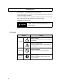
Definition of Safety Notices and Information
The following notation is used in this manual to provide precautions required to
ensure safe usage of the product.
The safety precautions that are provided are extremely important to safety. Always
read and heed the information provided in all safety precautions.
The following notation is used.
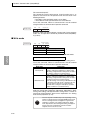
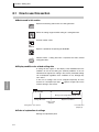
Caution
Indicates a potentially hazardous situation which, if not
avoided, may result in minor or moderate injury or in
property damage.
● Symbols
Symbol
Meaning
General Caution
Indicates non-specific general cautions, warnings
and dangers.
Caution
Electrical Shock Caution
Indicates possibility of electric shock under specific conditions.
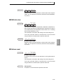
IV
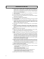
Prohibition
General Prohibition
Indicates non-specific general prohibitions.
Mandatory
Caution
General Caution
Indicates non-specific general cautions, warnings, and dangers.
● Precautions
CAUTION
Do not touch any of the terminals or terminal blocks while power is
being supplied. Doing so may occasionally result in minor injury
due to electric shock.
Do not touch the terminals, or electronic components or patterns
on the PCB within 1 minute after turning OFF the power. Doing so
may occasionally result in minor injury due to electric shock.
Do not allow pieces of metal, wire clippings, or fine metallic shavings or filings from installation to enter the product. Doing so may
occasionally result in electric shock, fire, or malfunction.
Do not use the product in locations where flammable or explosive
gases are present. Doing so may occasionally result in minor or
moderate explosion, causing minor or moderate injury, or property
damage.
Do not attempt to disassemble, repair, or modify the product.
Doing so may occasionally result in minor injury due to electric
shock.
Tighten the screws on the terminal block and the connector locking screws securely using a tightening torque within the following
ranges. Loose screws may occasionally cause fire, resulting in
minor or moderate injury, or damage to the equipment.
Terminal block screws: 0.40 to 0.56 N·m
Perform correct setting of the product according to the application.
Failure to do so may occasionally cause unexpected operation,
resulting in minor or moderate injury, or damage to the equipment.
Ensure safety in the event of product failure by taking safety measures, such as installing a separate overheating prevention alarm
system. Product failure may occasionally prevent control, or operation of alarm outputs, resulting in damage to the connected facilities and equipment.
Do not use the equipment for measurements within Measurement
Categories II, III, or IV (according to IEC61010-1). Doing so may
occasionally cause unexpected operation, resulting in minor or
moderate injury, or damage to the equipment. Use the equipment
for measurements only within the Measurement Category for
which the product is designed.
The service life of the output relays depends on the switching
capacity and switching conditions. Consider the actual application
conditions and use the product within the rated load and electrical
service life. Using the product beyond its service life may occasionally result in contact welding or burning.
V
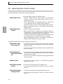
Precautions for Safe Use
(1) Use and store the product within the specified ambient temperature and
humidity ranges. If several products are mounted side-by-side or arranged in a
vertical line, the heat dissipation will cause the internal temperature of the
products to rise, shortening the service life. If necessary, cool the products
using a fan or other cooling method.
(2) Provide sufficient space around the product for heat dissipation. Do not block the
vents on the product.
(3) Use the product within the noted supply voltage and rated load.
(4) Be sure to confirm the name and polarity for each terminal before wiring the
terminal block and connectors.
(5) Do not connect anything to unused terminals.
(6) Use the specified size of crimp terminals (M3, width: 5.8 mm max.) for wiring
the terminal block.
(7) To connect bare wires to the terminal block, use AWG22 to AWG14 (crosssectional area: 0.326 to 2.081 mm2) to wire the power supply terminals and
AWG28 to AWG16 (cross-sectional area: 0.081 to 1.309 mm 2 ) for other
terminals. (Length of exposed wire: 6 to 8 mm)
(8) Ensure that the rated voltage is achieved no longer than 2 s after turning the
power ON.
(9) Turn OFF the power first before drawing out the product. Never touch the
terminals or the electronic components, or subject them to physical shock.
When inserting the product, do not allow the electronic components to contact
the case.
(10) Do not remove the inner circuit board.
(11) Output turns OFF when shifting to the initial setting level in certain modes.
Take this into consideration when setting up the control system.
(12) Allow the product to warm up for at least 30 minutes after the power is turned
ON.
(13) Install surge absorbers or noise filters in devices near the product that generate
noise (in particular, devices with an inductance component, such as motors,
transformers, solenoids, and magnetic coils). If a noise filter is used for the
power supply, check the voltage and current, and install the noise filter as close
as possible to the product. Separate the product as far as possible from
devices generating strong high-frequency noise (e.g., high-frequency welders
and high-frequency sewing machines) or surges.
Do not tie noise filter input/output wires together.
(14) Keep the wiring for the product's terminal block and connector separate from
high-voltage, high-current power lines to prevent inductive noise. Do not run the
wiring parallel to or in the same cable as power lines. The influence of noise
can also be reduced by using separate wiring ducts or shield lines.
(15) Install an external switch or circuit breaker and label them clearly so that the
operator can quickly turn OFF the power.
(16) Do not use the product in the following locations:
· Locations where dust or corrosive gases (in particular, sulfuric or ammonia
gas) are present.
· Locations where icing or condensation may occur.
· Locations exposed to direct sunlight.
· Locations subject to excessive shock or vibration.
· Locations where the product may come into contact with water or oil.
· Locations subject to direct radiant heat from heating equipment.
· Locations subject to extreme temperature changes.
(17) Cleaning: Do not use thinners. Use commercially available alcohol.
VI
Precautions for Correct Use
● Service Life
Use the product within the following temperature and humidity ranges:
Temperature: −10 to 55°C (no icing or condensation)
Humidity: 25% to 85%
When the product is installed inside a control panel, make sure that the temperature
around the product, not the temperature around the control panel, does not exceed
55°C.
The service life of this product and similar electronic devices is determined not only
by the number of switching operations of relays but also by the service life of
internal electronic components. Component service life is affected by the ambient
temperature: the higher the temperature becomes, the shorter the service life
becomes and, the lower the temperature becomes, the longer the service life
becomes. Therefore, the service life can be extended by lowering the temperature
of the product.
Be sure to install the product according to the specified conditions. Otherwise, the
heat generated by the product will cause the internal temperature to rise, shortening the service life. If necessary, cool the product using fans or other means of air
ventilation.
When providing forced cooling, however, be careful not to cool down the terminals
sections alone to avoid measurement errors.
● Noise Countermeasures
To prevent inductive noise, separate the wiring for the product's terminal block and
connector from high-voltage, high-current power lines. Do not run the wiring parallel
to or in the same cable as power lines. The influence of noise can also be reduced
by using separate wiring ducts or shield lines.
Install surge absorbers or noise filters in devices near the product that generate
noise (in particular, devices with an inductance component, such as motors, transformers, solenoids, and magnetic coils).
If a noise filter is used for the power supply, check the voltage and current, and
install the noise filter as close as possible to the product.
Separate the product as far as possible from devices generating strong highfrequency noise (e.g., high-frequency welders and high-frequency sewing
machines) or surges.
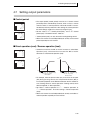
● Measurement Accuracy
When extending the thermocouple lead wire, be sure to use a compensating wire
that matches the thermocouple type.
When extending the lead wire of the platinum resistance thermometer, be sure to
use wires that have low resistance, and make sure that the resistances of the three
lead wires are the same.
If the measurement accuracy is low, check whether the input shift is set correctly.
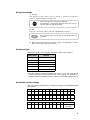
● Waterproofing
The degree of protection is as shown below.
Front panel
Rear case
Terminals
IP66
IP20
IP00
VII
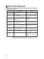
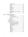
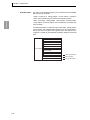
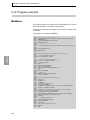
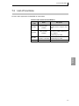
About this Manual
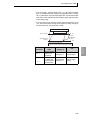
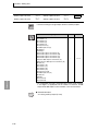
● How to use the manual
Purpose
Related section
Contents
General explanation of the E5AR/ER
Section 1 Overview
Explains the features, part names,
and main functions of the E5AR/ER.
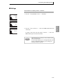
Setup
Section 2 Preparations
Section 3 Typical Control Examples
Explains how to set up the E5AR/ER
for operation (mounting, wiring, initial
settings).
Basic operation of
the E5AR/ER
Section 4 Settings Required for Basic
Control
Section 8 Setting Data
Advanced functions
of the E5AR/ER
Section 5 Functions and Operations
Section 8 Setting Data
Communication
functions
Section 6 Communication (CompoWay/
F)
Section 7 Communication (Modbus)
User calibration
Section 9 User Calibration
Explains calibration procedures that
can be performed by the user.
Troubleshooting
Section 10 Troubleshooting
Explains what to do when you
encounter a problem.
Appendix
Explains the basic functions of the
E5AR/ER.
Explains how to use the customized
functions (scaling, SP ramp, etc.) to
get the most out of the E5AR/ER.
Explains how to use communicationbased functions.
Product specifications. List of settings.
Can be used to make a copy of your
settings.
For details on using DeviceNet communications functions, refer to the E5AR/E5ER
Digital Controller DeviceNet Communications User’s Manual (H124).
VIII
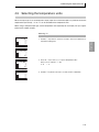
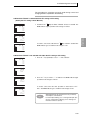
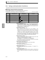
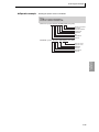
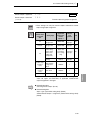
● Special markings
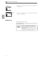
(1) Important
This appears in cases where incorrect settings or operation will prevent a
function from achieving the expected result.
Set the input type before setting the scaling value.
If the input type is changed after setting the scaling value, the scaling value will be automatically initialized.
Important
(2) Hint
This gives useful hints, advice, and other supplemental information.
The rise and fall values of the SP ramp of the E5AR/ER can be set
separately.
Hint
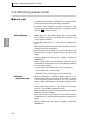
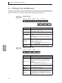
(3) Marks used to indicate "Function", "Setting", "Monitor", and "Reference" in "Setting
Data" in Section 8 are explained in Section 8.
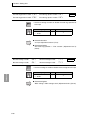
● Abbreviations
Abbreviations used in the setting data, illustrations, and text are as follows.
Abbreviation
Meaning
PV
Present value
SP
Set point
SV
Set value
AT
Auto-tuning (A.T)
EU
Unit of industrial quantity*
ch
Channel
* Data after scaling is shown in industrial units such as °C, m, and g, and "EU" is
used to indicate the minimum increment of such a quantity. For example, the
minimum increment of 50.02 m is 0.01 m, and thus 1 EU would be equal to 0.01 m.
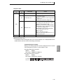
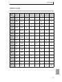
● Notation used for settings
Letters, numbers and abbreviations in settings that appear in the E5AR/ER display
are as follows.
a
b
c
d
e
f
g
h
i
j
k
l
m
A
B
C
D
E
F
G
H
I
J
K
L
M
n
o
p
q
r
s
t
u
v
w
x
y
z
N
O
P
Q
R
S
T
U
V
W
X
Y
Z
0
1
2
3
4
5
6
7
8
9
-1
0
1
2
3
4
5
6
7
8
9
-1 (Most significant digit)
IX
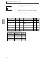
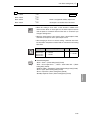
● Revision History
The revision code of this manual is given at the end of the catalog number at the
bottom left of the back cover. The following table outlines the changes made to the
manual during each revision. Page numbers refer to the previous version.
Cat. No.
Revision code
Z182-E1-02
Date
Pages and changes
01
May 2003
Original production
02
February 2004
The following changes were made. Other changes were also made to improve general quality.
Introduction: Descriptions mainly on precautionary information updated.
Page 1-5: “Bar graph” added to the top list.
Page 1-6: “Function key 1” added to the “Auto/Manual key.”
Page 1-7: Note at the bottom of the page corrected.
Page 1-8: Event input assignment diagram corrected.
Page 1-10: Control/transfer output allocation diagram corrected.
Page 1-12: Item 11 corrected to “Communications method.”
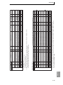
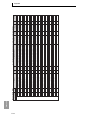
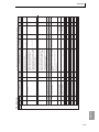
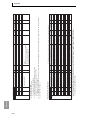
Pages 2-4 to 2-7: Terminal arrangement graphics corrected.
Page 2-8: Paragraph below the table deleted.
Page 2-9: Note added below the table.
Page 2-10: E5ER graphic on the right side deleted and “E5ER” on the left graphic changed to
“E5ER-@4@@.”
Page 2-11: “Event inputs 3 to 7” corrected to “event inputs 3 to 6” in two paragraphs under
Event inputs (terminals).
Page 3-11 (and throughout the manual): “Control initial setting level 2” corrected to “Control
initial setting 2 level.”
Page 3-16: The RSP indicator in the graphic under RUN level (Ch 2) corrected to OFF from ON.
Page 4-7: “PID adjustment level” corrected to “PID setting level.”
Page 4-22: Auxiliary output assignment diagram corrected.
Page 4-25: Item 8 “Press the level key twice” corrected to “Press the level key three times.”
Page 4-31: Item (1) “About two seconds” corrected to “About four seconds.”
Page 5-9: Monitor and setting range for SP ramp time unit in the top table corrected.
Page 5-30: “Auto/Manual (Adjustment level)” corrected to “Auto/Manual (RUN level)” under
Auto/Manual.
Page 8-12: DOTC: Disturbance time constant under Adjustment level corrected to “0.01-99.99.”
Pages 8-15, 8-16, 8-19, 8-27, 8-31, and 8-32: “PID Set No.” corrected to “PID.”
Page 8-26: The seven segment display (7.LSP) at the right top placed in a white box.
Page 8-35: Description added to RSPH and RSPL in the bottom graphic.
Page 8-46: Description under Setting range in the top table corrected.
Page 8-49: The second “Cascade standard control” in the bottom table corrected to “Cascade
heating/cooling control.”
Page 8-51: The default value under straight-line approximation corrected from ON to OFF.
Page A-2: Note 3 added below the Unit Ratings table.
Page A-2: “Outflow current: Approx. 7 mA” under Unit ratings corrected to “Short-circuit current:
Approx. 4 mA.”
Page A-3: “(±5% FS)± digit or less” under Indication accuracy corrected to “(±5% FS)± 1 digit
max.”
Page A-3: “0.2 to 99.9 seconds” under Control period corrected to “0.2 to 99.0 seconds.”
Page A-3: “Acceleration: 10 m/s2” under Vibration tolerance corrected to “Acceleration: 20 m/
s2.”
Page A-19: Description under Setting (monitor) value for 0E0C corrected.
Page A-20: Description under Setting (monitor) value for 0E20 corrected.
Page A-22: The second “Cascade standard control” in the table corrected to “Cascade heating/
cooling control.”
Page A-30: DOTC: Disturbance time constant under Adjustment level corrected to “0.01-99.99.”
X
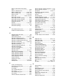
Contents
Introduction - - - - - - - - - - - - - - - - - - - - - - - - - - - I
Precaution in using the product - - - - - - - - - - - - - I
Precautions - - - - - - - - - - - - - - - - - - - - - - - - - -IV
Precautions for Safe Use - - - - - - - - - - - - - - - - -VI
Precautions for Correct Use - - - - - - - - - - - - - - VII
About this Manual - - - - - - - - - - - - - - - - - - - - - VIII
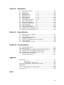
Section 1
Overview
1.1
1.2
1.3
Section 2
Preparations
2.1
2.2
Section 3
Main Features of the E5AR/ER .................................................................. 1-2
Inputs .................................................................................................. 1-2
Controller ............................................................................................ 1-2
Outputs ............................................................................................... 1-3
Part Names and Functions ......................................................................... 1-4
Front .................................................................................................... 1-4
How to read the display ...................................................................... 1-5
Explanation of the keys ....................................................................... 1-6
Input/output Configuration and Main Functions ......................................... 1-7
Input/output configuration ................................................................... 1-7
Main functions ..................................................................................... 1-8
Explanation of Model Numbers ......................................................... 1-12
Installation .................................................................................................. 2-2
Dimensions ......................................................................................... 2-2
Installation ........................................................................................... 2-2
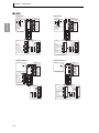
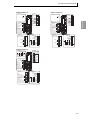
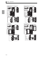
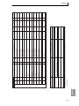
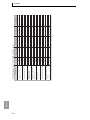
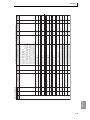
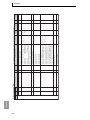
How to Use the Terminals .......................................................................... 2-4
E5AR ................................................................................................... 2-4
E5ER ................................................................................................... 2-8
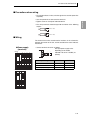
Precautions when wiring ................................................................... 2-11
Wiring ................................................................................................ 2-11
Typical Control Examples
3.1
3.2
3.3
Standard control ......................................................................................... 3-2
Application .......................................................................................... 3-2
Wiring .................................................................................................. 3-2
Settings ............................................................................................... 3-3
Adjustment .......................................................................................... 3-4
Heating/cooling control of a chemical reaction device ............................... 3-5
Application .......................................................................................... 3-5
Wiring .................................................................................................. 3-6
Settings ............................................................................................... 3-6
Adjustment .......................................................................................... 3-7
Settings for heating/cooling control ..................................................... 3-8
Position proportional control of a ceramic kiln ............................................ 3-9
Application .......................................................................................... 3-9
Wiring ................................................................................................ 3-10
Settings ............................................................................................. 3-10
Adjustment ........................................................................................ 3-11
Settings for position proportional control ........................................... 3-12
XI
3.4
3.5
Section 4
Settings Required for Basic Control
4.1
4.2
4.3
4.4
4.5
4.6
4.7
4.8
4.9
4.10
4.11
4.12
4.13
4.14
4.15
Section 5
Setting levels and key operation ................................................................. 4-2
Set values .................................................................................................. 4-4
Initial setting examples ............................................................................... 4-5
Setting the input type ................................................................................. 4-8
Input type ............................................................................................ 4-8
Scaling ................................................................................................ 4-9
Selecting the temperature units ............................................................... 4-11
Selecting the control mode ....................................................................... 4-12
Setting output parameters ........................................................................ 4-13
Control period ................................................................................... 4-13
Direct operation (cool) / Reverse operation (heat) ............................ 4-13
Output type ....................................................................................... 4-14
Output assignment ............................................................................ 4-14
Setting and changing the SP .................................................................... 4-16
Setting and changing the SP ............................................................ 4-16
Performing ON/OFF control ..................................................................... 4-17
ON/OFF Control ................................................................................ 4-17
Settings ............................................................................................. 4-18
Determining the PID constants (AT, manual settings) .............................. 4-19
AT (Auto-tuning) ................................................................................ 4-19
Manual settings ................................................................................. 4-21
Using auxiliary output ............................................................................... 4-22
Auxiliary output assignment .............................................................. 4-22
Alarm types ....................................................................................... 4-23
Alarm values ..................................................................................... 4-24
Settings ............................................................................................. 4-24
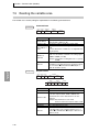
Starting and stopping control ................................................................... 4-26
Control run / Control stop .................................................................. 4-26
Settings ............................................................................................. 4-27
Performing manual control ....................................................................... 4-28
Manual mode .................................................................................... 4-28
Changing channels .................................................................................. 4-30
Changing channels ........................................................................... 4-30
Operational considerations ...................................................................... 4-31
Functions and Operations
5.1
XII
Cascade control of reflow ovens .............................................................. 3-13
Application ........................................................................................ 3-13
Wiring ................................................................................................ 3-14
Settings ............................................................................................. 3-14
Adjustment ........................................................................................ 3-15
Ratio control of dyeing machines ............................................................. 3-18
Application ........................................................................................ 3-18
Wiring ................................................................................................ 3-19
Settings ............................................................................................. 3-19
Adjustment ........................................................................................ 3-21
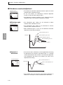
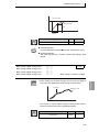
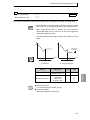
Input adjustment functions ......................................................................... 5-2
Input shift ............................................................................................ 5-2
First order lag operation ...................................................................... 5-5
Move average ..................................................................................... 5-5
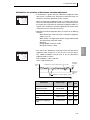
Broken-line approximation .................................................................. 5-6
Extraction of square root operations ................................................... 5-7
Other input adjustment functions ........................................................ 5-7
5.2
5.3
5.4
5.5
5.6
5.7
5.8
5.9
Section 6
Control functions ........................................................................................ 5-8
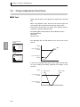
SP ramp .............................................................................................. 5-8
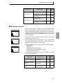
Banks .................................................................................................. 5-9
SP limits ............................................................................................ 5-12
PID sets ............................................................................................ 5-12
Disturbance overshoot adjustment ................................................... 5-14
Output adjustment functions .................................................................... 5-16
MV limit ............................................................................................. 5-16
MV change rate limit ......................................................................... 5-17
MV at Stop ........................................................................................ 5-18
MV at PV error .................................................................................. 5-18
Display and key adjustment functions ...................................................... 5-19
Display scan ...................................................................................... 5-19
PF settings (function keys) ................................................................ 5-21
Other display and key adjustment functions ..................................... 5-23
Protecting settings ................................................................................... 5-24
Protect ............................................................................................... 5-24
Alarm adjustment functions ...................................................................... 5-26
Alarm hysteresis ............................................................................... 5-26
Standby sequence ............................................................................ 5-26
Alarm latch ........................................................................................ 5-27
Close in alarm/Open in alarm ........................................................... 5-27
Using event input ..................................................................................... 5-29
Event input allocation ........................................................................ 5-29
Using transfer output ................................................................................ 5-32
Transfer output settings .................................................................... 5-32
Using communication functions ............................................................... 5-34
Setting communication parameters .................................................. 5-34
Write via communication ................................................................... 5-35
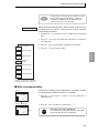
Communication (CompoWay/F)
6.1
6.2
6.3
6.4
6.5
6.6
6.7
6.8
6.9
Communication method ............................................................................. 6-2
CompoWay/F communication protocol ............................................... 6-2
Communication specifications ............................................................ 6-2
Transfer protocol (Communication/CompoWay/F) ............................. 6-2
Frames (Communication/CompoWay/F) .................................................... 6-4
Command frame ................................................................................. 6-4
Response frame .................................................................................. 6-5
FINS-mini text ............................................................................................ 6-6
Variable areas ............................................................................................ 6-7
Reading the variable area .......................................................................... 6-9
Writing to the variable area ...................................................................... 6-10
Operation commands (Communication/CompoWay/F) ............................ 6-11
Setting areas ............................................................................................ 6-13
Commands and responses (Communication/CompoWay/F) ................... 6-14
Monitor value read (Communication/CompoWay/F) ......................... 6-14
Setting data read (Communication/CompoWay/F) ........................... 6-15
Monitor value / setting data compound read
(Communication/CompoWay/F) ........................................................ 6-16
Protect level setting data write .......................................................... 6-17
Setting data write (Communication/CompoWay/F) ........................... 6-17
Setting data compound write (Communication/CompoWay/F) ......... 6-18
Monitor value / setting data compound read store (write) ................. 6-19
Monitor value / setting data compound read store check (read) ....... 6-20
Monitor value / setting data compound store read ............................ 6-20
XIII
Write via communication ................................................................... 6-21
Control Run / Control Stop ................................................................ 6-21
Bank change ..................................................................................... 6-22
AT execute ........................................................................................ 6-23
AT cancel .......................................................................................... 6-23
Write mode ........................................................................................ 6-24
RAM data store ................................................................................. 6-25
Software reset ................................................................................... 6-25
Move to setting area 1 ...................................................................... 6-26
Move to protect level ......................................................................... 6-26
Auto / Manual .................................................................................... 6-27
Initialize settings ................................................................................ 6-27
Cancel latch ...................................................................................... 6-28
SP mode ........................................................................................... 6-28
Read machine attributes ................................................................... 6-29
Controller status read (Communication/CompoWay/F) .................... 6-30
Echo back test .................................................................................. 6-31
6.10 Program example ..................................................................................... 6-32
N88Basic ........................................................................................... 6-32
Section 7
Communication (Modbus)
7.1
7.2
7.3
7.4
7.5
7.6
7.7
7.8
7.9
XIV
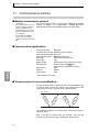
Communication method ............................................................................. 7-2
Modbus communication protocol ........................................................ 7-2
Communication specifications ............................................................ 7-2
Transfer protocol (Communication/Modbus) ....................................... 7-2
Frames ....................................................................................................... 7-4
Command frame ................................................................................. 7-4
Response frame .................................................................................. 7-5
List of functions .......................................................................................... 7-7
Variable area .............................................................................................. 7-8
Reading the variable area ........................................................................ 7-10
Writing to the variable area ...................................................................... 7-12
Operation commands (Communication/Modbus) ..................................... 7-14
Setting areas ............................................................................................ 7-16
Commands and responses (Communication/Modbus) ............................ 7-17
Monitor value read (Communication/Modbus) .................................. 7-17
Read setting data (Communication/Modbus) .................................... 7-18
Write setting data to protect level ...................................................... 7-19
Write setting data (Communication/Modbus) .................................... 7-19
Write via communication ................................................................... 7-21
Control Run / Control Stop ................................................................ 7-21
Bank change ..................................................................................... 7-22
AT execute ........................................................................................ 7-23
AT cancel .......................................................................................... 7-23
Write mode ........................................................................................ 7-24
RAM data store ................................................................................. 7-25
Software reset ................................................................................... 7-25
Move to setting area 1 ...................................................................... 7-26
Move to protect level ......................................................................... 7-26
Auto / Manual .................................................................................... 7-27
Initialize settings ................................................................................ 7-27
Cancel latch ...................................................................................... 7-28
SP mode ........................................................................................... 7-28
Echo back test .................................................................................. 7-29
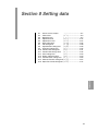
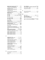
Section 8
Setting data
8.1
8.2
8.3
8.4
8.5
8.6
8.7
8.8
8.9
8.10
8.11
8.12
8.13
8.14
8.15
8.16
Section 9
How to use this section
.................................................................. 8-2
Protect level
(l.prt) ..................................................... 8-3
Operation level
( ) ........................................................... 8-5
Adjustment level
(l.adj) ................................................... 8-12
Adjustment 2 level
(l.ad2) ................................................... 8-22
Bank setting level
(l.bnk) ................................................... 8-26
PID setting level
(l.pid) ................................................... 8-30
Approximation setting level
(l.tec) ................................................... 8-33
Input initial setting level
(l.0) ........................................................ 8-35
Control initial setting level
(l.1) ........................................................ 8-41
Control initial setting 2 level
(l.2) ........................................................ 8-45
Alarm setting level
(l.3) ........................................................ 8-53
Display adjustment level
(l.4) ........................................................ 8-59
Communication setting level (l.5) ........................................................ 8-63
Advanced function setting level (l.adf) ................................................... 8-67
Expansion control setting level (l.exc) ................................................... 8-72
User calibration
9.1
9.2
9.3
9.4
9.5
9.6
9.7
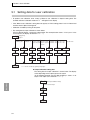
Setting data for user calibration ................................................................. 9-2
User calibration .......................................................................................... 9-4
Thermocouple input calibration .................................................................. 9-5
Analog input calibration .............................................................................. 9-8
Resistance temperature input sensor calibration ..................................... 9-10
Output calibration ..................................................................................... 9-12
Inspecting indicator accuracy ................................................................... 9-13
Section 10 Troubleshooting
10.1
10.2
10.3
10.4
10.5
10.6
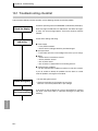
Troubleshooting checklist ......................................................................... 10-2
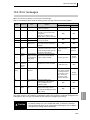
Error messages ........................................................................................ 10-3
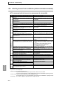
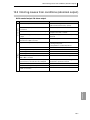
Inferring causes from conditions (abnormal measured values) ............... 10-4
Inferring causes from conditions (abnormal control) ................................ 10-5
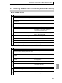
Inferring causes from conditions (abnormal output) ................................. 10-7
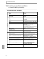
Inferring causes from conditions
(communication problems) ....................................................................... 10-8
Appendix
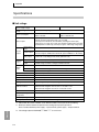
Specifications .......................................................................................................A-2
Unit ratings ..........................................................................................A-2
Unit performance specifications ..........................................................A-3
Sensor input setting ranges · Indicator (control) ranges .......................................A-4
ASCII Codes ........................................................................................................A-5
Setting list .............................................................................................................A-6
Initialization due to setting changes ..................................................A-28
Setting data list ...................................................................................................A-30
Index
XV
1.1
1.2
1.3
Overview
Section 1 Overview
Main Features of the E5AR/ER ......................................... 1-2
Part Names and Functions ................................................ 1-4
Input/output Configuration and Main Functions ................. 1-7
1-1
Overview
Section 1 Overview
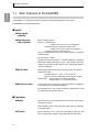
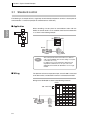
1.1 Main Features of the E5AR/ER
The E5AR/ER is an advanced controller that features high-speed and high-precision control.
The E5AR/ER has the following features:
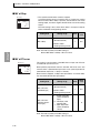
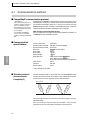
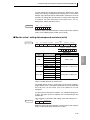
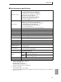
■ Inputs
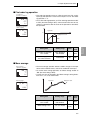
● High-speed
sampling
● High accuracy/
high resolution
• 50-ms sampling period
• Accuracy Thermocouple:
(Larger of ±0.1% PV or ±1°C) ±1 digit max
Platinum resistance temperature input sensor:
(Larger of ±0.1% PV or ±0.5°C) ±1 digit max
Analog input: (±0.1% FS)±1 digit max
(For non-standard specifications, see "Specifications" on page A-2
of the Appendix)
• Input resolution: 1/100°C
(Pt 100: Resolution range 0.01°C, -150.00 to 150.00°C is available)
• High-speed sampling and high accuracy / high resolution are simultaneously achieved to enable high-accuracy, high-speed control to
match the application.
● Multi-inputs
• Wide range of temperature inputs and analog inputs are available.
Temperature inputs :
Thermocouples K, J, T, E, L, U, N, R, S, B, W
Platinum resistance temperature input sensors: Pt 100
Analog inputs: Current inputs: 4 to 20 mA, 0 to 20mA
Voltage inputs: 1 to 5 V, 0 to 5V, 0 to 10V
● Multi-point inputs
• A 2-input type and a 4-point input type are available for the E5AR. A
2-point input type is available for the E5ER.
• All multi-point inputs also support multi-input, eliminating the need
for an externally connected converter.
■ Controller
● Banks
• Up to 8 banks can be created to store SPs (local SP), alarm values,
and PID set numbers.
• Switch between banks by bank selection (event input, key operation,
or communication).
● PID sets
1-2
• Up to 8 PID sets can be created to store settings (PID value, MV
limits, and automatic selection range upper limit) for PID control.
• Selection of a PID is possible not only by direct specification of the
PID Set No. in a bank, but also by PID set automatic selection
according to the present value and deviation.
● Ample control
modes and control
functions
• Supports typical control modes (standard control, heating/cooling
control, proportional control, cascade control). Note that proportional
control and cascade control are only possible on 2-input types.
• Floating control or closed control can be selected for position
proportional types. Floating control allows position proportional
control without a potentiometer.
• Remote SP
Two-input types can use an external input for the set point.
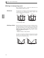
• SP ramp function
This limits the amount of change of the set point based on the rate of
change (SP ramp value). This function is useful for control applications such as firing ceramics where sudden changes in temperature
are not desirable.
The E5AR/ER allows an SP ramp rise value and fall value to be set
separately.
■ Outputs
● Multi-output
• Multi-output supporting current output and voltage output (pulse) is
available.
● High resolution
• Resolution of current output
0 to 20 mA: Approx. 54,000 resolution
4 to 20 mA: Approx. 43,000 resolution
● Control period
• The control period can be set as short as 0.2 seconds, allowing
precise time sharing proportional control.
1-3
Overview
1.1 Main Features of the E5AR/ER
Overview
Section 1 Overview
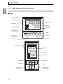
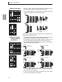
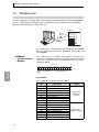
1.2 Part Names and Functions
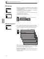
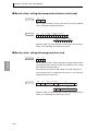
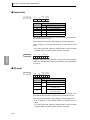
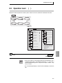
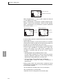
■ Front
Operation indicator
SUB1 SUB2 SUB3 SUB4
Channel indication
8CH 8.8.8.8.8
Bar graph
8.8.8.8.8
8.8.8.8
Operation indicator
PV
Indicator 1
SV
Indicator 2
MV
Indicator 3
OUT1 OUT2 OUT3 OUT4 STOP RSP
Function key 1
Auto/Manual key
PF 1
PF2/CH
Up key
A/M
Down key
Function key 2
Channel key
E5AR
Mode key
Level key
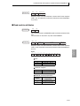
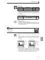
Operation indicator
SUB1 SUB2 SUB3 SUB4
8.8.8.8.8
8.8.8.8.8
8.8.8.8
PV
SV
MV
Indicator 1
Indicator 2
Indicator 3
OUT1 OUT2 STOP RSP
Down key
Mode key
Level key
Up key
PF 1
Function key 1
Auto/Manual key
1-4
PF2/CH
A/M
E5ER
Function key 2
Channel key
1.2 Part Names and Functions
Overview
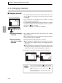
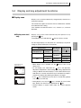
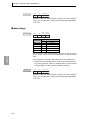
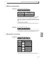
■ How to read the display
● Display 1
Shows the present value and the setting data’s name or error
name. (Red)
● Display 2
Shows the set point value and the set value of the setting data. (Green)
● Display 3
Shows the Manipulated Variable MV and the bank number or level
name. (Orange)
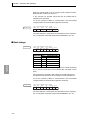
● Channel indication
Shows the set channel number.
Only appears on a multi-point input type. On a single input type, the
display is always off. (Orange)
The E5ER shows the corresponding channel when the "CH2"
operation indicator is lit.
● Bar graph
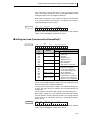
Shows a bar graph of the settings.
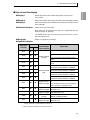
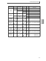
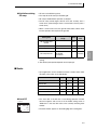
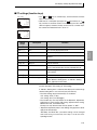
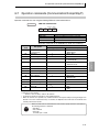
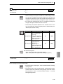
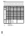
● Operation indicators
Operation
indicators
*1:
Model
Common
indicator/Single
E5AR E5ER channel indicator
OUT1
●
●
OUT2
●
●
OUT3
●
–
OUT4
●
–
SUB1
●
●
SUB2
●
●
SUB3
●
●
SUB4
●
●
STOP
●
●
Single channel
indicator (orange)
RSP
●
●
MANU
●
●
CMW
●
●
CH2
–
●
Single channel
indicator (orange)
Single channel
indicator (orange)
Common indicator
(orange)
Single channel
indicator (orange)
Common indicator
(orange)
Common indicator
(red)
Explanation
Turns on/off when control output 1 is ON/OFF.
*2
Turns on/off when control output 2 is ON/OFF.
*2
Turns on/off when control output 3 is ON/
OFF.*2
Turns on/off when control output 4 is ON/
OFF.*2
Turns on/off when the output function
assigned to auxiliary output 1 is ON/OFF.
Turns on/off when the output function
assigned to auxiliary output 2 is ON/OFF.
Turns on/off when the output function
assigned to auxiliary output 3 is ON/OFF.
Turns on/off when the output function
assigned to auxiliary output 4 is ON/OFF.
Turns on when operation stops. Otherwise is
off.
Turns on during control at an event input or
when "run/stop" is switched to stop.
Turns on when the SP mode is set to remote.
Otherwise is off.
Turns on when operation is set to manual
mode. Otherwise is off.
Turns on/off when write via communication is
ON/OFF (enabled/disabled).
Turns on when the displayed channel is 2.
Otherwise is off.
● : Indicates that the model has the function. Note that function may be disabled depending on the
settings, and in this case the indicator is always off.
–: Indicates that the model does not have the function.
1-5
Overview
Section 1 Overview
*2:
When the control output is current output, the indicator turns off when the MV is 0% or less, and turns
on when the manipulated variable is greater than 0%.
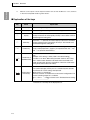
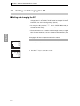
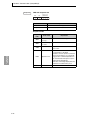
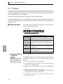
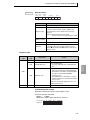
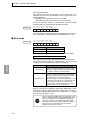
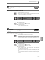
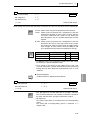
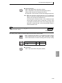
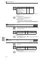
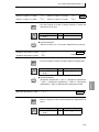
■ Explanation of the keys
Key
Name
L
Level key
Press to change setting levels.
M
Mode key
Press to change the setting data within a setting level.
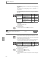
U
Up key
Each time U is pressed, the value of display 2 increases. Hold down
the key to increase the value quickly. The key is also used to scroll forward through the setting item.
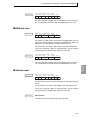
D
Down key
Each time D is pressed, the value of display 2 decreases. Hold down
the key to decrease the value quickly. The key is also used to scroll
backward through the setting item.
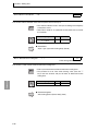
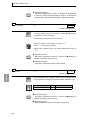
L+M
Protect key
Press to change to a protected level. See "4.1 Configuration of Setting
Levels and Key Operation" (page 4-2) for operation when the L key
and M are pressed simultaneously.
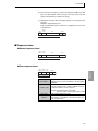
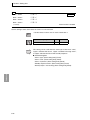
Function key 1/
Auto/Manual key
When pressed, this function key activates the function set in "PF1 setting".
Example: "PF1 setting" is "A/M" ("A/M" is the default setting)
Functions as an Auto / Manual key (hereafter shown as the A key)
that is used to switch between auto mode and manual mode. The
mode changes when the key is pressed for at least one second (the
timing of key release does not matter).
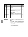
Function key 2 /
channel key
Functions as a channel key for multi-channel control.*
For 1-point input types, the key acts as a function key that activates
the function set in "PF2 setting" when pressed.
When used as a channel key:
Switches channels on models with a multi-channel configuration. The
channel switching sequence is as follows:
CH1 → CH2 → ··· → Highest channel set in "Enabled channel setting"
↑___________________↓
PF1
PF2
/A
/
CH
Explanation
*Functions as a start key for the displayed scan.
1-6
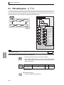
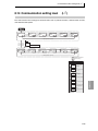
1.3 Input/output Configuration and Main Functions
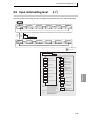
Overview
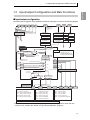
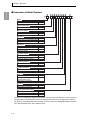
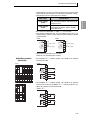
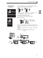
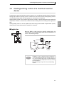
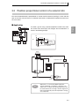
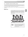
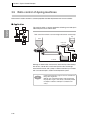
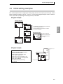
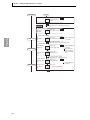
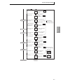
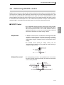
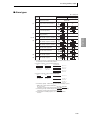
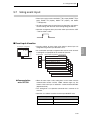
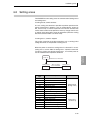
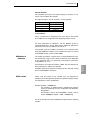
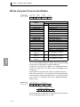
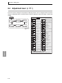
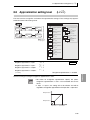
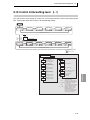
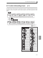
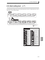
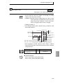
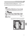
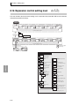
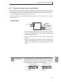
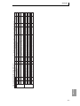
1.3 Input/output Configuration and Main Functions
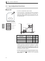
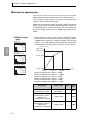
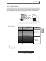
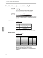
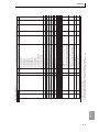
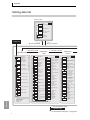
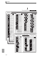
■ Input/output configuration
The input/output configuration of the E5AR/ER and internal setting item are shown in the following diagram.
EV1
EV2
EV3
EV4
EV5
IN1
EV6
IN2
IN3
IN4
Input type switch
"Input type"
"Temperature units"
"Scaling"
Event input assignment
Extraction of
square root 1
Extraction of Extraction of
square root 2square root 3 Extraction of
square root 4
Move average 1
Move average
2 average 3
Move
Move average 4
First order
lag operation 1
First order
First order
First order
lag operation 2
lag operation 3lag operation 4
"Control mode" is control with remote SP
Broken-line
approximation 1
Channel 1
RSP.1
PV.1
Remote SP
Control mode
LRSP.1
Local SP
BNK2.1
BNK1.1
BNK0.1
Bank No. 0
Local SP, AlarmBank
value,
No.PID
1 set
+
SP ramp
−
Local SP, Alarm value, PID set
Bank No. 7
Local SP, Alarm value, PID set
Local SP
PID
[SP mode]
= Standard control
Heating/cooling control
Standard control with remote SP
Heating/cooling control with remote SP
∗
Direct/reverse action
MV change rate limiter
Input error
Remote SP input error
Potentiometer input error
MV limiter
ALM4.1
ALM3.1
ALM2.1
ALM1.1
MV at PV error
Error
RNRS.1
Run
SERR.1
MV at stop
Stop
MNAT.1
Auto
RSER.1
Manual MV
Auxiliary output assignments
Manual
Standard type
"Control mode"
Standard control
Position proportional type
Heating/cooling control
Dead band
MVH.1
MVC.1
Position proportional dead band
VLVO.1
VLVC.1
Control / Transfer
output assignments
OUT1
PV.1 Channel 1 PV
RSP.1 Channel 1 Remote SP
MVH.1 Channel 1 MV (heating side)
MVL.1 Channel 1 MV (cooling side)
VLVO.1 Channel 1 MV (open side)
VLVC.1 Channel 1 MV (closed side)
OUT2
OUT3
LRSP.1 Channel 1
Local/Remote SP mode
BNK0.1 Channel 1 bank (bit 0)
BNK1.1 Channel 1 bank (bit 1)
BNK2.1 Channel 1 bank (bit 2)
RNRS.1 Channel 1 RUN/STOP
MNAT.1 Channel 1 manual/auto
OUT4
ALM1.1
ALM2.1
ALM3.1
ALM4.1
SERR.1
RSER.1
SUB1
SUB2
SUB3
SUB4
Channel 1 Alarm 1
Channel 1 Alarm 2
Channel 1 Alarm 3
Channel 1 Alarm 4
Channel 1 Input error
Channel 1 Remote SP input error
Multi-point input types have the same setting data for channels 2 to 4 depending on the number of input points.
* Cascade standard control, Cascade heating/cooling control, position proportional control and ratio
control are also available. See "Section 3, Typical Control Examples" (page 3-1).
1-7
Overview
Section 1 Overview
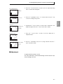
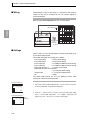
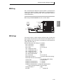
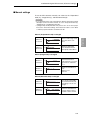
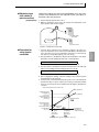
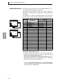
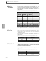
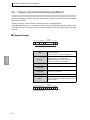
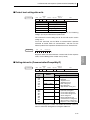
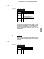
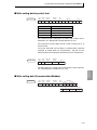
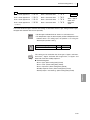
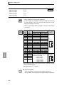
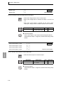
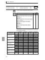
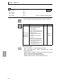
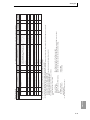
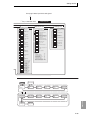
■ Main functions
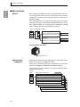
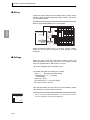
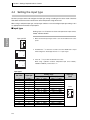
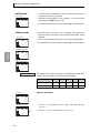
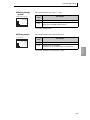
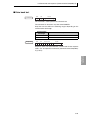
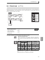
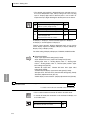
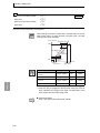
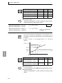
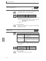
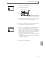
● Input
After selecting the temperature input (TC: thermocouple or PT: resistance temperature input sensor) or analog input (current input or
voltage input), with the input type switch select the input type in
parameter setting.
If the input type SW is set to temperature input (resistance temperature input sensor or thermocouple), the temperature unit can be set.
If the input type SW is set to analog input (current input or voltage
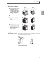
input), scaling and the decimal point position can be set.
Input Input type SW Input type
IN1
IN2
IN3
IN4
TC.PT
IN1
TYPE
ANALOG
Temperature input
Resistance temperature input sensor: Pt 100
Thermocouples: K, J, T, E, L, U, N, R, S, B, W
Temperature units
Analog input
Current input: 4 to 20 mA, 0 to 20 mA
Voltage input: 1 to 5 V, 0 to 5 V, 0 to 10 V
Scaling
Decimal point position
Location of input type switch
Input type SW (bottom)
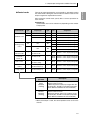
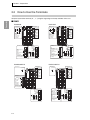
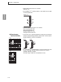
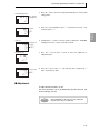
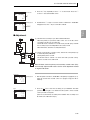
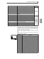
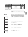
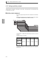
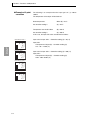
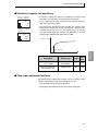
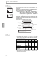
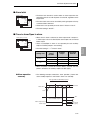
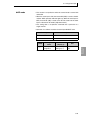
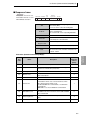
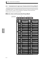
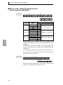
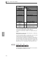
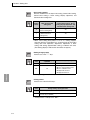
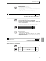
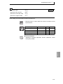
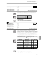
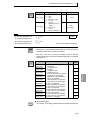
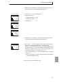
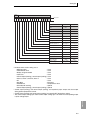
● Event input
assignment
An operation command can be assigned to each event input. If event
input is to be used, use an E5AR/ER-@@B/D.
In the case of a multi-point input type, assignment data can be set for
channels 2 and higher as needed for the number of channels.
The operation instruction "Write via communication OFF/ON" is
common to all channels
Event
Input
Event input assignment
Channel 1
EV1
EV2
EV3
EV4
EV5
EV6
1-8
Write via communication OFF/ON
Channel 2
Channel 1 Bank No. (bit 0)
Communication write OFF/ON
Channel 3
Channel 1 Bank No. (bit 1)
Channel 1 Bank No. (bit 0)
ChannelCommunication
1 Bank No. (bit write
2) OFF/ON
Channel 4
Channel 1 Bank No. (bit 1)
1 Bank No. (bit 0)
ChannelChannel
1 Communication
Run/Stop
Channel
1 Bank No. (bitwrite
2) OFF/ON
1 Bank No. (bit 1)
ChannelChannel
1 Channel
Auto/Manual
1 Bank No. (bit 0)
Channel
1 Run/Stop
1 Bank
No. (bit 2)
ChannelChannel
1 Channel
SP mode
1(remote/local)
Bank No. (bit 1)
Channel 1 Auto/Manual
Channel 1 Run/Stop
Channel
1 Bank
No. (bit 2)
Channel
2SP mode
(remote/local)
Channel 1 Auto/Manual
Channel 1 Run/Stop
Channel 1 Auto/Manual
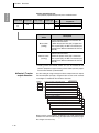
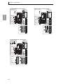
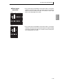
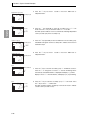
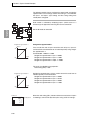
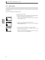
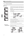
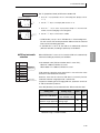
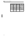
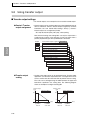
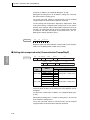
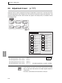
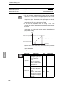
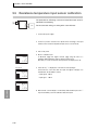
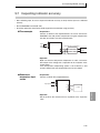
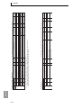
● Control mode
The type of control performed by each controller is selected by setting
the control mode. Setting the control mode sets default values for the
output assignments required for the control.
After setting the control mode, specify direct / reverse operation for
each channel.
Standard type
Control modes that can be selected vary depending on the number
of input points.
Control mode
1-input
type
2-input type
4-input
type
Output
Control / Transfer output
assignment
IN1
IN1
IN1
OUT1
Channel 1 control output (heating side)
IN2
Standard control
IN1
IN2
OUT2
Channel 2 control output (heating side)
IN3
OUT3
Channel 3 control output (heating side)
IN4
OUT4
Channel 4 control output (heating side)
OUT1
Channel 1 control output (heating side)
OUT2
Channel 1 control output (cooling side)
OUT3
Channel 2 control output (heating side)
OUT4
Channel 1 control output (cooling side)
–
OUT1
Channel 1 control output (heating side)
–
OUT1
OUT2
Channel 1 control output (heating side)
Channel 1 control output (cooling side)
IN1
IN1
IN2
IN2
Heating/cooling
control
IN1
IN2: Remote SP
Standard control
with remote SP
–
Heating/cooling
control with
remote SP
–
Ratio control
–
IN1
IN2: Ratio setting
–
OUT1
Channel 1 control output (heating side)
Cascade standard
control
–
IN1: Primary loop
IN2: Secondary loop
–
OUT1
Channel 2 control output (heating side)
Cascade heating/
cooling control
–
IN1: Primary loop
IN2: Secondary loop
–
OUT1
OUT2
Channel 1 control output (heating side)
Channel 1 control output (cooling side)
IN1
IN2: Remote SP
Direct/Reverse
operation
Description
Direct
operation
(cooling)
Control whereby the MV is increased as the
present value increases
(When the present value (PV) is higher than the
set point (SP), the MV is increased in proportion
to the difference between the PV and the SP.)
Reverse
operation
(heating)
Control whereby the MV is decreased as the
present value increases
(When the present value (PV) is lower than the
set point (SP), the MV is increased in proportion
to the difference between the PV and the SP.)
• When pulse output is used, the control period must be set for each
channel.
1-9
Overview
1.3 Input/output Configuration and Main Functions
Overview
Section 1 Overview
Position proportional type
The position proportional type only uses standard control.
Control mode
1-input type
2-input type
4-input type
Standard control
IN1
–
–
Output
Control / Transfer output
assignment
OUT1
Channel 1 control output (open side)
OUT2
Channel 1 control output (closed side)
Direct/Reverse
action
Description
Direct action
(cooling)
Control whereby the MV is increased as the
present value increases
(When the present value (PV) is higher than
the set point (SP), the MV is increased in proportion to the difference between the PV and
the SP.)
Reverse action
(heating)
Control whereby the MV is decreased as the
present value increases
(When the present value (PV) is lower than
the set point (SP), the MV is increased in proportion to the difference between the PV and
the SP.)
• Floating control and closed control can also be selected for the
position proportional type. Floating control allows position proportional control without a potentiometer.
● Control / Transfer
output allocation
Use this setting to assign what type of data is output from each output.
For the multi-point input type, assignment data can be set for channels
2 and higher as needed for the number of channels.
Output
OUT1
OUT2
OUT3
OUT4
Control / transfer output allocation
Channel 1 control output (heat)
Channel 1 control output (cool)
Channel 1 SP
Channel 1 ramp SP
Channel 1 present value
Channel 1 control output (heat)
Channel 1 control output (cool)
Channel 1 valve opening
Channel 2 control output (heat)
Channel 2 control output (cool)
Channel 1
Channel 2
Channel 3
Channel 4
Channel 3 control output (heat)
Channel 4 control output (heat)
When used for control output, assignments are made automatically
based on the control mode setting as explained on the previous page.
No changes are necessary.
1-10
When used for transfer output type, assign the data to be transferred to
an unused output.
For outputs supporting multi-output, specify pulse voltage output or
linear current output according to the multi-output output type.
For linear current output, 0 to 20 mA or 4 to 20 mA can be selected.
Pulse voltage output is 12 V DC, 40 mA.
Output
OUT1
OUT2
OUT3
OUT4
● Auxiliary output
assignments
Multi-output output type
Pulse voltage output
Linear current output
Linear current output output type
0 - 20 mA
4 - 20 mA
Use this setting to assign what type of data is output from each
auxiliary output.
For the multi-point input type, assignment data can be set for channels
2 and higher as needed for the number of channels. The U-ALM output
is an OR output with alarm functions 1 to 4 for all channels.
Auxiliary output
SUB1
SUB2
SUB3
SUB4
Auxiliary output assignment Channel 1
Channel 1 alarm 1
Channel 1 alarm 2
Channel 1 alarm 3
Channel 2
Channel
1 alarm
4 1
Channel
2 alarm
Channel 3
Channel
1 input
error2
Channel
2 alarm
Channel
3
alarm
1
Channel 4
Channel
1 RSP
input3error
Channel
2 alarm
Channel
3 alarm 2
Channel
Channel
2 alarm44alarm 1
Channel
3 alarm
3 2
Channel
alarm
U-ALM
output
Channel
2 input 4error
Channel
3 alarm
4 3
Channel
4 alarm
Channel 4 alarm 4
Channel 4 input error
All Channels
All-channel alarm 1 OR output
All-channel alarm 2 OR output
All-channel alarm 3 OR output
All-channel alarm 4 OR output
All-channel input error OR output
All-channel RSP input error OR output
1-11
Overview
1.3 Input/output Configuration and Main Functions
Overview
Section 1 Overview
■ Explanation of Model Numbers
E5
Size
A (96 x 96 mm)
E (48 x 96 mm)
A
E
Constant/Program
Constant
Blank
Control method
Standard / heat cool
Position proportional
Blank
P
R−
−
Output 1
Relay, relay
R
Pulse output + pulse voltage/current Q
Current + current
C
Output 2
None
Relay, relay
Pulse output + pulse voltage/current
Current + current
Blank
R
Q
C
Auxiliary output
None
Blank
Relay 4 output SPST-NO common 4
Transistor output, 2 points
T
Option function 1
None
RS-485 communication
Blank
3
Option function 2
None
Events, 4 points
Blank
D
Input 1
Multi input + event input, 2 points B
Multi input + FB
F
(Potentiometer input)
Multi input + multi input
W
Input 2
None
Multi input + multi input
Blank
W
Communications method
None
CompoWay/F
DeviceNet
Blank
FLK
DRT
The above is an explanation based on functionality. There may be some differences from the product
line depending on the combination of features selected. Please check the catalogue when ordering.
For details on using DeviceNet communications functions, refer to the E5AR/E5ER Digital Controller
DeviceNet Communications User’s Manual (H124).
1-12
Preparations
Section 2 Preparations
2.1
2.2
Installation ......................................................................... 2-2
How to Use the Terminals.................................................. 2-4
2-1
Section 2 Preparations
2.1 Installation
Preparations
■ Dimensions
E5AR
110
95
11.5
3
96
2
1
SUB1 SUB2 SUB3 SUB4
1
2
96
CMW
8.8.8.8.8
8.8.8.8
MANU
PV
SV
111
8.8.8.8.8
8
MV
OUT1 OUT2 OUT3 OUT4 STOP RSP
PF 1
2
3
3
4
4
5
5
6
6
1
1
2
PF2/CH
2
3
3
4
4
A/M
E5AR
5
5
6
6
E5ER
11.5
3
48
110
95
2
SUB1 SUB2 SUB3 SUB4
8.8.8.8.8
8.8.8.8
PV
SV
111
96
8.8.8.8.8
CH2
CMW
MV
MANU
OUT1 OUT2 STOP RSP
■ Installation
● Panel cutout dimensions
E5AR
E5ER
45+0.6
0
60 or higher
2-2
120 or higher
92 +0.8
0
120 or higher
110 or higher
92+0.8
0
92
+0.8
0
2.1 Installation
● Installation procedure
E5AR
E5ER
Watertight packing
Watertight packing
Preparations
If the front of the unit needs to
be watertight, attach the
provided watertight packing.
If the front of the unit does not
need to be watertight, the
watertight packing does not
need to be attached.
Insert the unit into the cutout
in the panel.
Insert the accompanying
fittings into the grooves on the
top and bottom of the rear
case.
Gradually tighten the screws
in the top and bottom fittings,
alternating between each so
that they are balanced.
Tighten until the ratchet turns
without engaging.
● Pulling the unit out
Normally there is no need to pull out the unit, however, it can be pulled
out if needed for maintenance purposes.
1
2
1
0.4
2.0
When pulling the unit out, place a cloth over the screwdriver to prevent
scratches and other damage.
2-3
Section 2 Preparations
2.2 How to Use the Terminals
Preparations
Verify the layout of the terminals (A - , 1 - ) using the engravings on the top and sides of the case
■ E5AR
E5AR-Q4B
E5AR-A4B-500
24 VAC/DC 100-240 VAC
+
E5AR-C4B
A
B C D E
2
+
-
3
4
5
6
1
Input power supply
depends on the
model.
100 to 240 VAC
or 24 VAC/DC
(no polarity)
E5AR-A4B-500
24 VAC/DC 100-240 VAC
+
E5AR-A4B-500
Auxiliary outputs
B (Relay outputs)
1
2
1
COM
2
SUB1
3
SUB2
4
5
6
COM
Input power supply
depends on the
model.
100 to 240 VAC
or 24 VAC/DC
(no polarity)
SUB3
SUB4
1
COM
2
SUB1
3
SUB2
5
6
1
4
5
6
COM
1
J K
F G H I
E53-ARCC
1
EV2
2
COM
3
PT
4
5
6
K
+
-
-
+
+
I
V
TC
(Current) (Voltage)
(Thermocouple)
(Resistance thermometer)
OUT2
Current output
4-20 mA DC, 500 Ω max.
0-20 mA DC, 500 Ω max.
(Switch using
output type setting.)
OUT1
Current output
4-20 mA DC, 500 Ω max.
0-20 mA DC, 500 Ω max.
(Switch using output
type setting.)
E5AR-Q43B-FLK
100-240 VAC
1
B(+)
RS-485
A(-)
2
OUT2
+
Voltage output
3
12 V 40 mA
4
OUT1
+
Voltage output
5
12 V 40 mA or
Current output
6
4-20 mA DC, 500 Ω max.
F
0-20 mA DC, 500 Ω max.
(Switch using output type setting.)
SUB4
1
+
+
-
J K
E5AR-A4B-500
Event inputs
EV1
2
EV2
3
COM
2
3
+
4
5
6
F
-
-
-
+
I
+
V
PT
1
TC
4
5
6
K
(Current) (Voltage)
(Thermocouple)
(Resistance thermometer)
E5AR-C43B-FLK
E5AR-A4B-500
E53-ARQC3
SUB3
2
5
6
E5AR-A4B-500
Event inputs
EV1
E5AR-A4B-500
Auxiliary outputs
B (Relay outputs)
3
4
5
6
2
OUT2
Voltage output 12 V + 3
40 mA
4
OUT1
Voltage output 12 V +
5
40 mA or
Current output
6
4-20 mA DC, 500 Ω max.
F
0-20 mA DC, 500 Ω max.
(Switch using output type setting.)
A
B C D E
E5AR-A4B-500
Auxiliary outputs
B (Relay outputs)
E5AR-A4B-500
100-240 VAC
A
B C D E
E5AR-A4B-500
Auxiliary outputs
B (Relay outputs)
1
1
COM
1
1
COM
2
2
SUB1
2
2
SUB1
3
4
3
SUB2
SUB2
COM
3
4
3
4
5
6
4
5
6
COM
5
6
1
SUB3
SUB4
5
6
1
2
2
3
4
3
4
5
6
5
6
F G H I
F G H I
J K
E5AR-A4B-500
Event inputs
EV1
2
COM
3
PT
4
5
6
K
-
-
I
+
V
1
EV2
+
+
TC
(Current) (Voltage)
(Thermocouple)
(Resistance thermometer)
2-4
-
3
4
F G H I
B C D E
2
+
3
4
E53-ARQC
+
A
1
E53-ARCC3
+
B(+)
RS-485
A(-) OUT2
Current output
+
4-20 mA DC, 500 Ω max.
0-20 mA DC, 500 Ω max. (Switch using output
+
type setting.)
OUT1
Current output
4-20 mA DC, 500 Ω max.
0-20 mA DC, 500 Ω max.
(Switch using output
type setting.)
1
SUB4
J K
E5AR-A4B-500
Event inputs
EV1
2
EV2
3
COM
4
5
6
F
SUB3
2
3
+
-
-
I
+
V
-
PT
1
+
TC
4
5
6
K
(Current) (Voltage)
(Thermocouple)
(Resistance thermometer)
2.2 How to Use the Terminals
E5AR-C43DB-FLK
E5AR-A4B-500
100-240 VAC
E53-ARQC3
+
1
B(+)
RS-485
A(-)
2
OUT2
+
Voltage output
3
12 V 40 mA
4
OUT1
+
Voltage output
5
12 V 40 mA or
Current output
6
4-20 mA DC, 500 Ω max.
F
0-20 mA DC, 500 Ω max.
(Switch using output type setting.)
A
B C D E
E5AR-A4B-500
Auxiliary outputs
B (Relay outputs)
E5AR-A4B-500
100-240 VAC
A
B C D E
E5AR-A4B-500
Auxiliary outputs
B (Relay outputs)
1
1
COM
1
1
COM
2
2
SUB1
2
2
SUB1
3
4
3
SUB2
SUB2
COM
3
4
3
4
5
6
4
5
6
COM
5
6
1
2
3
4
5
6
SUB3
SUB4
E53-ARB4
Event inputs
E
1
EV3
2
EV4
3
EV5
4
5
6
EV6
F G H I
J K
COM
E5AR-A4B-500
Event inputs
EV1
2
COM
3
+
-
-
I
+
V
+
TC
PT
2
3
4
5
6
4
5
6
K
(Current) (Voltage)
(Thermocouple)
(Resistance thermometer)
SUB3
SUB4
E53-ARB4
Event inputs
E
1
EV3
2
EV4
3
EV5
4
5
6
EV6
F G H I
E53-ARCC3
+
B(+)
RS-485
A(-) OUT2
Current output
+
4-20 mA DC, 500 Ω max.
0-20 mA DC, 500 Ω max. (Switch using output
type setting.)
+
OUT1
Current output
4-20 mA DC, 500 Ω max.
0-20 mA DC, 500 Ω max.
(Switch using output
type setting.)
1
EV2
5
6
1
1
J K
3
4
5
6
F
COM
E5AR-A4B-500
Event inputs
EV1
2
2
COM
3
-
I
+
V
1
EV2
+
-
-
PT
Preparations
E5AR-Q43DB-FLK
+
TC
4
5
6
K
(Current) (Voltage)
(Thermocouple)
(Resistance thermometer)
E5AR-QC43DB-FLK
E5AR-A4B-500
24 VAC/DC 100-240 VAC
+
+
Input power supply depends
on the model.
100 to 240 VAC
or 24 VAC/DC (no polarity)
E53-ARQC3
B(+)
RS-485
A(-)
+
-
1
2
OUT2
+
Voltage output
3
12 V 40 mA
4
OUT1
+
Voltage output
5
12 V 40 mA or
6
Current output
4-20 mA DC, 500 Ω max. F
0-20 mA DC, 500 Ω max.
(Switch using output type setting.)
A
B C D E
E5AR-A4B-500
Auxiliary outputs
B (Relay outputs)
1
1
COM
2
2
SUB1
3
4
3
SUB2
4
5
6
COM
5
6
1
2
3
4
5
6
SUB4
E53-ARB4
Event inputs
E
1
EV3
2
EV4
3
EV5
4
5
6
EV6
F G H I
E53-ARCC
OUT4
Current output
4-20 mA DC, 500 max.
0-20 mA DC, 500 max.
(Switch using output
type setting.)
OUT3
Current output
4-20 mA DC, 500 Ω max.
0-20 mA DC, 500 Ω max.
(Switch using output
type setting.)
SUB3
1
J K
2
+
+
-
3
4
5
6
G
COM
E5AR-A4B-500
Event inputs
EV1
2
COM
3
+
-
-
I
+
V
1
EV2
-
PT
+
TC
4
5
6
K
(Current) (Voltage)
(Thermocouple)
(Resistance thermometer)
2-5
Section 2 Preparations
E5AR-Q43DW-FLK (2-loop Control)
E5AR-A4W-500
Auxiliary outputs
B (Relay outputs)
Preparations
A(-)
+
-
1
2
+
OUT2
3
Voltage output
12 V 40 mA
4
OUT1
+
5
Voltage output
12 V 40 mA or 6
Current output
4-20 mA DC, 500 Ω max. F
0-20 mA DC, 500 Ω max.
(Switch using output type setting.)
F G H I J K
COM
2
SUB1
3
SUB2
4
5
6
COM
SUB3
SUB4
E53-ARB4
Event inputs
E
1
EV3
2
EV4
3
EV5
4
5
6
EV6
COM
E5AR-A4W-500
+
1
+
V
-
PT
-
-
+
TC
-
+
-
Input 1
+
I
V
PT
+
TC
2
3
4
5
6
K
(Current) (Voltage)
(Thermocouple)
(Resistance thermometer)
E5AR-QQ43DW-FLK (2-loop Control)
E5AR-A4W-500
Auxiliary outputs
B (Relay outputs)
E5AR-A4W-500
24 VAC/DC 100-240 VAC
+
A
+
Input power supply depend
on the model.
100 to 240 VAC
or 24 VAC/DC (no polarity)
1
A(-)
2
OUT2
+
3
Voltage output
12 V 40 mA
4
OUT1
+
Voltage output
5
12 V 40 mA or 6
Current output
4-20 mA DC, 500 Ω max. F
0-20 mA DC, 500 Ω max.
(Switch using output type setting.)
F G H I J K
SUB1
3
SUB2
4
5
6
COM
SUB3
SUB4
E53-ARB4
Event inputs
E
1
EV3
2
EV4
3
EV5
4
5
6
COM
E53-ARQC
E5AR-A4W-500
1
-
-
2
+
TC
3
Input 2
I
+
V
PT
-
-
1
2
OUT4
+
Voltage output
3
12 V 40 mA
4
OUT3
+
Voltage output 12 V
5
40 mA or
Current output
6
4-20 mA DC, 500 Ω max.
G
0-20 mA, DC 500 Ω max.
(Switch using output type setting.)
2-6
COM
2
EV6
+
+
-
1
+
B(+)
RS-485
-
E53-ARQC3
B C D E
1
2
3
4
5
6
1
2
3
4
5
6
-
Input 1
+
I
V
E53-ARCC3
+
B(+)
RS-485
A(-) OUT2
Current output
+
4-20 mA DC, 500 Ω max.
0-20 mA DC, 500 Ω max. (Switch using output
type setting.)
+
OUT1
Current output
4-20 mA DC, 500 Ω max.
0-20 mA DC, 500 Ω max.
(Switch using output
type setting.)
1
2
3
4
5
6
F
B C D E
F G H I J K
1
COM
2
SUB1
3
SUB2
4
5
6
COM
SUB3
SUB4
E53-ARB4
Event inputs
E
1
EV3
2
EV4
3
EV5
4
5
6
EV6
COM
E5AR-A4W-500
Input 2
I
A
1
2
3
4
5
6
1
2
3
4
5
6
PT
+
TC
4
5
6
K
(Current) (Voltage)
(Thermocouple)
(Resistance thermometer)
1
-
-
2
+
TC
3
Input 2
I
+
V
PT
-
-
B(+)
RS-485
1
E5AR-A4W-500
Auxiliary outputs
B (Relay outputs)
100-240 VAC
+
E53-ARQC3
B C D E
E5AR-A4W-500
+
A
1
2
3
4
5
6
1
2
3
4
5
6
E5AR-C43DW-FLK (2-loop Control)
-
E5AR-A4W-500
100-240 VAC
-
Input 1
+
I
V
PT
+
TC
4
5
6
K
(Current) (Voltage)
(Thermocouple)
(Resistance thermometer)
2.2 How to Use the Terminals
E5AR-A4WW-500
Auxiliary outputs
B (Relay outputs)
2
3
4
5
6
F
F G H I J K
COM
2
SUB1
3
SUB2
4
5
6
COM
SUB3
E53-ARQC3
SUB4
B(+)
E53-ARB4
Event inputs
E
1
EV3
2
EV4
3
EV5
4
5
6
EV6
COM
E53-ARCC
+
-
-
+
I
-
V
PT
-
+
-
Input 1(K)
Input 3(J)
V
+
-
Input power supply
depends
on the model.
100 to 240 VAC
or 24 VAC/DC
(no polarity)
+
TC
3
-
4
5
6
PT
(Current) (Voltage)
(Thermocouple)
(Resistance thermometer)
J, K
A
B C D E
E5AR-PA4F-500
Auxiliary outputs
B (Relay outputs)
1
1
COM
2
2
SUB1
3
4
3
SUB2
4
5
6
COM
2
3
4
5
6
SUB3
SUB4
E53-ARB4
Event inputs
E
1
EV3
2
EV4
3
EV5
4
5
6
EV6
F G H I
J K
COM
E5AR-PA4F-500
Potentiometer
O
E53-ARRR
1
OUT2
OUT1
3
4
5
6
F
1
COM
2
SUB1
3
SUB2
4
5
6
COM
SUB3
SUB4
E53-ARB4
Event inputs
E
1
EV3
2
EV4
3
EV5
4
5
6
EV6
COM
E5AR-A4WW-500
2
OUT4
+
Voltage output
3
12 V 21 mA
OUT3
4
Voltage output 12 V
+
5
21 mA or
Current output
6
4-20 mA DC, 500 Ω max.
0-20 mA DC, 500 Ω max. G
(Switch using output type setting.)
Input 2(K)
Input 4(J)
1
I
-
-
2
+
+
TC
3
-
4
5
6
V
PT
-
Input 1(K)
Input 3(J)
+
I
V
PT
+
TC
(Current) (Voltage)
(Thermocouple)
(Resistance thermometer)
J, K
E5AR-PRQ43DF-FLK
5
6
1
2
F G H I J K
1
2
+
TC
+
I
B C D E
E53-ARQC
E5AR-PR4DF
E5AR-PA4F-500
24 VAC/DC 100-240 VAC
+
1
1
1
Input 2(K)
Input 4(J)
+
RS-485
A(-)
2
+
OUT2
3
Voltage output
12 V 21 mA
4
OUT1
+
5
Voltage output
12 V 21 mA or 6
Current output
4-20 mA DC, 500 Ω max. F
0-20 mA DC, 500 Ω max.
(Switch using output type setting.)
E5AR-A4WW-500
OUT4
Current output
2
4-20 mA DC, 500 Ω max. +
3
0-20 mA DC, 500 Ω max.
(Switch using output
4
type setting.)
+
5
OUT3
Current output
6
4-20 mA DC, 500 Ω max.
0-20 mA DC, 500 Ω max. G
(Switch using output type setting.)
A
1
2
3
4
5
6
1
2
3
4
5
6
-
1
1
E5AR-A4WW-500
Auxiliary outputs
B (Relay outputs)
100-240 VAC
+
E53-ARCC3
+
B(+)
RS-485
A(-) OUT2
Current output
+
4-20 mA DC, 500 Ω max.
0-20 mA DC, 500 Ω max. (Switch using output
+
type setting.)
OUT1
Current output
4-20 mA DC, 500 Ω max.
0-20 mA DC, 500 Ω max.
(Switch using output
type setting.)
B C D E
1
2
3
4
5
6
1
2
3
4
5
6
E5AR-A4WW-500
-
A
+
Input power supply depends
on the model.
100 to 240 VAC
or 24 VAC/DC (no polarity)
E5AR-QQ43DWW-FLK (4-loop Control)
+
E5AR-A4W-500
24 VAC/DC 100-240 VAC
+
Preparations
E5AR-CC43DWW-FLK (4-loop Control)
W
Relay outputs
250 VAC 1 A
C
+
Closed
-
-
Open
-
+
I
V
+
PT
TC
E5AR-PA4F-500
24 VAC/DC 100-240 VAC
+
+
Input power supply depends
on the model.
100 to 240 VAC
or 24 VAC/DC (no polarity)
E53-ARQC
A
B C D E
1
1
COM
2
2
SUB1
3
4
3
SUB2
4
5
6
COM
5
6
1
1
2
OUT4
+
Voltage output
3
12 V 40 mA
4
OUT3
Voltage output
+
5
12 V 40 mA or
Current output
6
4-20 mA DC, 500 Ω max.
G
0-20 mA DC, 500 Ω max.
(Switch using output type setting.)
2
B(+)
RS-485
A(-)
3
4
5
6
K
(Current) (Voltage)
(Thermocouple)
(Resistance thermometer)
OUT2
OUT1
SUB3
SUB4
E53-ARB4
Event inputs
E
1
3
4
EV3
2
EV4
3
5
6
EV5
4
5
6
2
EV6
F G H I
E53-ARRR3
1
E5AR-PA4F-500
Auxiliary outputs
B (Relay outputs)
J K
COM
E5AR-PA4F-500
Potentiometer
O
1
2
3
4
5
6
F
W
Relay output
250 VAC 1 A
Closed
C
+
-
-
Open
I
+
V
+
PT
TC
1
2
3
4
5
6
K
(Current) (Voltage)
(Thermocouple)
(Resistance thermometer)
2-7
Section 2 Preparations
■ E5ER
E5ER-Q4B
E5ER-C4B
Preparations
-
+
+
-
B
A
E5ER-AB-500
24 VAC/DC 100-240 VAC
E53-ARR4
Auxiliary outputs
B (Relay outputs)
1
Input power supply
depends on the model.
100 to 240 VAC
or 24 VAC/DC
(no polarity)
2
1
COM
3
4
2
SUB1
3
SUB2
5
6
1
4
5
6
COM
A
E5ER-AB-500
24 VAC/DC 100-240 VAC
-
+
+
-
Input power supply
depends on the model.
100 to 240 VAC
or 24 VAC/DC
(no polarity)
SUB3
SUB4
SUB1
3
SUB2
5
6
1
4
5
6
COM
3
4
5
6
5
6
1
EV2
2
COM
3
-
+
TC
PT
1
2
OUT2
Current output
+
3
4-20 mA DC, 500 Ω max.
0-20 mA DC, 500 Ω max. 4
(Switching by output
+
type setting)
5
OUT1
6
Current output
4-20 mA DC, 500 Ω max. C
0-20 mA DC, 500 Ω max.
(Switch using output type setting.)
4
5
6
E
-
+
V
I
(Current) (Voltage)
(Thermocouple)
(Resistance thermometer)
E5ER-Q43B-FLK
E5ER-AB-500
1
2
EV2
3
COM
+
-
-
+
V
I
4
5
6
E
-
PT
+
TC
(Current) (Voltage)
(Thermocouple)
(Resistance thermometer)
E5ER-C43B-FLK
A
100-240 VAC
SUB4
E5ER-AB-500
Event inputs
EV1
E53-ARCC
+
-
SUB3
C D E
E5ER-AB-500
Event inputs
EV1
2
OUT2
+
Voltage output
3
12 V 40 mA
4
OUT1
Voltage output
+
5
12 V 40 mA or
Current output
6
4-20 mA DC, 500 Ω max.
C
0-20 mA DC, 500 Ω max.
(Switch using output type setting.)
E53-ARR4
Auxiliary outputs
B (Relay outputs)
B
1
E5ER-AB-500
A
100-240 VAC
E53-ARR4
Auxiliary outputs
B (Relay outputs)
B
1
2
1
COM
2
1
COM
SUB1
2
3
SUB2
3
4
SUB1
3
4
2
3
SUB2
5
6
1
4
5
6
COM
5
6
1
4
5
6
COM
SUB3
SUB4
2
2
3
4
3
4
5
6
5
6
E53-ARCC3
2
COM
3
PT
4
5
6
E
-
I
+
V
1
EV2
+
-
SUB3
SUB4
C D E
C D E
E5ER-AB-500
Event inputs
EV1
+
TC
(Current) (Voltage)
(Thermocouple)
(Resistance thermometer)
2-8
COM
2
3
4
C D E
E53-ARQC3
+
B(+)
1
RS-485
A(-) - 2
OUT2
+
Voltage output
3
12 V 40 mA
OUT1
4
Voltage output
+
5
12 V 40 mA or
Current output
6
4-20 mA DC, 500 Ω max.
0-20 mA DC, 500 Ω max. C
(Switch using output type setting.)
1
3
4
2
1
E53-ARR4
Auxiliary outputs
B (Relay outputs)
2
2
E53-ARQC
B
1
RS-485
B(+)
+
1
A(-) - 2
OUT2
Current output
+
3
4-20 mA DC, 500 Ω max.
0-20 mA DC, 500 Ω max. 4
(Switch using output
+
type setting.)
5
OUT1
6
Current output
4-20 mA DC, 500 Ω max. C
0-20 mA DC, 500 Ω max.
(Switch using output type setting.)
E5ER-AB-500
Event inputs
EV1
2
COM
3
+
-
-
I
+
V
1
EV2
-
PT
+
TC
4
5
6
E
(Current) (Voltage)
(Thermocouple)
(Resistance thermocouple)
2.2 How to Use the Terminals
E5ER-AB-500
E5ER-CT3DB-FLK
A
100-240 VAC
E53-ARB4
B
1
2
3
4
5
6
1
2
E53-ARQC3
+
B(+)
1
RS-485
A(-)
2
OUT2
+
3
Voltage output
12 V 40 mA
4
OUT1
+
Voltage output
5
12 V 40 mA or
Current output
6
4-20 mA DC, 500 Ω max.
0-20 mA DC, 500 Ω max. C
(Switch using output type setting.)
SUB1
+
SUB2
-
2
2
EV4
3
EV5
4
5
6
3
4
3
4
5
6
C D E
E5ER-AB-500
Event inputs
EV1
1
2
+
4
5
6
D
D
-
-
+
V
I
-
PT
+
TC
4
5
6
E
(Current) (Voltage)
(Thermocouple)
(Resistance thermometer)
E53-ARB4
B
1
5
6
1
2
E53-ARCC3
+
B(+)
1
RS-485
A(-) - 2
OUT2
+
Current output
3
4-20 mA DC, 500 Ω max. 0-20 mA DC, 500 Ω max.
4
(Switch using output +
5
type setting.)
OUT1
6
Current output
4-20 mA DC, 500 Ω max. C
0-20 mA DC, 500 Ω max.
(Switch using output type setting.)
Auxiliary outputs
(Transistor outputs)
SUB1
SUB2
EV3
2
EV4
3
EV5
4
5
6
COM
5
6
C D E
1
3
-
4
5
6
D
D
-
B
1
3
4
+
+
Event inputs
EV6
E5ER-AB-500
Event inputs
EV1
2
3
COM
3
100-240 VAC
E53-ART2
EV2
2
+
EV3
COM
1
A
B
1
EV6
E53-ART2
Auxiliary outputs
(Transistor outputs)
E5ER-AB-500
Event inputs
Preparations
E5ER-QT3DB-FLK
2
COM
3
+
-
-
I
+
V
1
EV2
-
PT
+
TC
4
5
6
E
(Current) (Voltage)
(Thermocouple)
(Resistance thermometer)
E5ER-QC43B-FLK
E5ER-AB-500
24 VAC/DC 100-240 VAC
A
E53-ARR4
Auxiliary outputs
B (Relay outputs)
B
-
+
1
+
-
2
1
COM
3
4
2
SUB1
3
SUB2
5
6
1
2
4
5
6
COM
Input power supply depends
on the model.
100 to 240 VAC
or 24 VAC/DC (no polarity)
E53-ARQC3
+
B(+)
1
RS-485
A(-) - 2
OUT2
+
Voltage output
3
12 V 40 mA
4
OUT1
Voltage output
+
5
12 V 40 mA or
Current output
6
4-20 mA DC, 500 Ω max.
0-20 mA DC, 500 Ω max. C
(Switch using output type setting.)
SUB3
SUB4
3
4
5
6
C D E
E53-ARCC
1
2
OUT2
Current output
+
3
4-20 mA DC, 500 Ω max.
0-20 mA DC, 500 Ω max. 4
(Switch using output
+
type setting.)
5
OUT1
6
Current output
4-20 mA DC, 500 Ω max. D
0-20 mA DC, 500 Ω max.
(Switch using output type setting.)
E5ER-AB-500
Event inputs
EV1
2
COM
3
+
-
-
I
+
V
1
EV2
-
PT
+
TC
4
5
6
E
(Current) (Voltage)
(Thermocouple)
(Resistance thermometer)
2-9
Section 2 Preparations
1
+
-
2
3
4
5
6
1
2
E53-ARQC3
+
B(+)
1
RS-485
A(-) - 2
OUT2
+
3
Voltage output
12 V 40 mA
4
OUT1
+
Voltage output
5
12 V 40 mA or
Current output
6
4-20 mA DC, 500 Ω max.
0-20 mA DC, 500 Ω max. C
(Switch using output type setting.)
E5ER-AW-500
24 VAC/DC 100-240 VAC
B
1
Event inputs
EV3
2
EV4
3
EV5
4
5
6
EV6
COM
C D E
Input 2
1
-
2
3
-
4
5
6
D
D
SUB2
-
Input 1
+
V
PT
-
-
+
I
+
SUB1
+
-
2
+
TC
3
-
+
I
V
PT
+
TC
A
2
EV3
2
3
4
EV4
3
EV5
5
6
1
EV6
4
5
6
+
-
E53-ARRR
1
OUT1
B
1
1
Input power supply depends
on the model.
100 to 240 VAC
or 24 VAC/DC (no polarity)
Relay output
250 VAC 1 A
COM
5
6
1
2
Closed
Open
2
EV4
3
EV5
4
5
6
COM
3
4
5
6
C D E
1
Input 2
1
-
2
SUB1
+
3
-
4
5
6
D
D
+
SUB2
-
Input 1
I
+
V
PT
-
2
+
TC
3
+
TC
+
I
-
V
PT
4
5
6
E
(Current) (Voltage)
(Thermocouple)
(Resistance thermometer)
A
E5ER-PAF-500
24 VAC/DC 100-240 VAC
-
+
+
-
E53-ARRR3
+
B(+)
RS-485
A(-)
OUT2
5
6
OUT1
1
2
3
4
5
6
C
Relay output
250 VAC 1 A
+
+
-
O
1
W
2
C
3
4
5
6
D
D
+
-
-
I
+
V
+
PT
TC
1
2
3
4
5
6
E
(Current) (Voltage)
(Thermocouple)
(Resistance thermometer)
E53-ARR4
Auxiliary outputs
B (Relay outputs)
2
1
COM
3
4
2
SUB1
3
SUB2
5
6
1
4
5
6
COM
SUB3
SUB4
2
Closed
3
4
Open
5
6
C D E
E53-ARQC
E5ER-PAF-500
Potentiometer
B
1
Input power supply depends
on the model.
100 to 240 VAC or 24 VAC/DC
(no polarity)
3
4
Auxiliary outputs
(Transistor outputs)
SUB2
EV3
EV6
C D E
SUB1
B
1
E5ER-AW-500
Auxiliary outputs
(Transistor outputs)
2
E53-ART2
2-10
B
Event inputs
+
4
5
6
C
3
4
Event inputs
E5ER-PRQ43F-FLK
E53-ARB4
-
3
+
(Current) (Voltage)
(Thermocouple)
(Resistance thermometer)
E5ER-PAF-500
24 VAC/DC 100-240 VAC
OUT2
2
4
5
6
E
E5ER-PRTDF
2
-
E53-ART2
+
1
+
B(+)
1
RS-485
A(-) - 2
OUT2
+
Current output
3
4-20 mA DC, 500 Ω max.
0-20 mA DC, 500 Ω max.
4
(Switch using output
+
type setting.)
5
OUT1
6
Current output
4-20 mA DC, 500 Ω max. C
0-20 mA DC, 500 Ω max.
(Switch using output type setting.)
E5ER-AW-500
Auxiliary outputs
(Transistor outputs)
1
E53-ARCC3
5
6
E53-ART2
+
E53-ARB4
B
A
-
Input power supply depends
on the model.
100 to 240 VAC
or 24 VAC/DC (no polarity)
3
4
-
Preparations
Input power supply depends
on the model.
100 to 240 VAC
or 24 VAC/DC (no polarity)
B
-
+
E5ER-CT3DW-FLK (2-loop Control)
+
A
-
E53-ARB4
+
E5ER-AW-500
24 VAC/DC 100-240 VAC
-
E5ER-QT3DW-FLK (2-loop Control)
1
2
OUT4
+
Voltage output
3
12 V 40 mA
4
OUT3
+
Voltage output
5
12 V 40 mA or
Current output
6
4-20 mA DC, 500 Ω max.
D
0-20 mA DC, 500 Ω max.
(Switch using output type setting.)
E5ER-PAF-500
Potentiometer
O
W
C
+
-
-
I
+
V
+
PT
TC
1
2
3
4
5
6
E
(Current) (Voltage)
(Thermocouple)
(Resistance thermometer)
2.2 How to Use the Terminals
■ Precautions when wiring
• To avoid the effects of noise, wire the signal wires and the power line
separately.
• Tighten screws to a torque of 0.40 to 0.56 N•m.
• The crimp terminals should be type M3 and either of the following
shapes:
5.8 mm or less
5.8 mm or less
■ Wiring
The inside of the frame around terminal numbers in the schematics
indicates the interior of the unit, and the outside of the frame indicates
the exterior.
● Power supply
(terminals)
E5AR
A
B
C
D
E
1
2
3
4
5
6
1
2
3
4
5
6
1
2
3
4
5
6
1
2
3
4
5
6
F
G
H
I
J
• Connect terminals A1 to A2 as follows:
The input power supply varies
depending on the model.
A
+
100-240 V AC or 24 V AC/DC (no
1
polarity)
2
+
Input voltage
100-240 V AC 50/60Hz
24 V AC 50/60Hz
24 V DC (no polarity)
-
E5AR
E5ER
22 VA
15 VA
10 W
17 VA
11 VA
7W
K
E5ER
A
B
1
2
3
4
5
6
1
2
3
4
5
6
1
2
3
4
5
6
1
2
3
4
5
6
C
D
E
2-11
Preparations
• Use crimp terminals to connect to the terminals.
Section 2 Preparations
● Inputs (terminals)
E5AR
Preparations
A
B
C
1
2
3
4
5
6
1
2
3
4
5
6
D
E
1
2
3
4
5
6
1
IN4 IN2 2
3
4
IN3 IN1 5
6
F
G
H
I
J
• For Input 1 (IN1), connect terminals K4 to K6 on the E5AR, or E4 to
E6 on the E5ER, as follows according to the input type.
• For a multi-point input type, connect inputs 2 to 4 (IN2 to IN4) in the
same way according to the number of input points.
E5AR
IN1
4
K
IN2
1
IN3
4
IN4
1
5
2
5
2
6
3
6
3
K
K
J
J
IN1
4
IN2
1
E5ER
A
1
2
3
4
5
6
1
IN2 2
3
4
IN1 5
6
C
D
E5AR
B
C
D
E
1
2
3
4
5
6
1
2
3
4 OUT2 OUT4
5
OUT1 OUT3
6
F
G
1
2
3
4
5
6
1
2
3
4
5
6
H
I
I
Current
+
A
-
B
5
2
6
3
E
E
-
B
+
Pt
TC
Thermocouple Temperature
resistance
input sensor
V
Voltage
I
Current
J
E5AR
Pulse voltage output
Linear current output
+V
+V
OUT1 OUT2 OUT3 OUT4
5
6
K
+
-
F
3
4
+
-
F
5
6
+
-
G
3
4
+
+
OUT1 OUT2 OUT3 OUT4
5
L
6
-
G
GND
+
-
F
3
4
+
-
F
5
6
+
-
G
3
4
+
L
-
G
B
1
2
3
4
5
6
1
2
3
OUT2 OUT4
4
5
OUT1 OUT3
6
C
+
Pt
TC
V
Thermocouple Temperature Voltage
resistance
input sensor
• On the E5AR, control output 1 (OUT1) outputs to terminals F5 to F6,
and control output 2 (OUT2) outputs to terminals F3 to F4.
• On the E5ER, control output 1 (OUT1) outputs to terminals C5 to
C6, and control output 2 (OUT2) outputs to terminals C3 to C4.
• On a multi-point input type, output takes place from control output 3
(OUT3) and control output 4 (OUT4).
GND
E5ER
A
-
B
To prevent the appearance of error displays due to unused inputs, set
the Number of enabled channels.
E
● Control outputs /
Transfer outputs
(terminals)
A
-
B
E5ER
B
1
2
3
4
5
6
1
2
3
4
5
6
+
A
D
1
2
3
4
5
6
1
2
3
4
5
6
E
E5ER
Pulse voltage output
Linear current output
+V
+V
OUT1 OUT2 OUT3 OUT4
5
6
GND
C
+
-
3
4
C
+
-
5
6
D
+
-
3
4
D
+
+
OUT1 OUT2 OUT3 OUT4
5
L
6
-
GND
C
+
-
3
4
C
+
-
5
6
D
+
-
3
4
+
L
-
D
• If terminals
and
are used for pulse voltage output, approximately 2 V are output when the power is turned on. (Load resistance: 10 kΩ max. for 10 msec)
• In the case of linear current output, approximately 2 mA are output
for 1 second when the power is turned on.
2-12
2.2 How to Use the Terminals
• Control outputs that are not used for control can be used for transfer
output with the "control output / transfer output assignment" setting.
• Specifications for each output type are as follows:
Pulse voltage
output
Linear current
output
Specifications
Output voltage: 12 V DC+15%, –20%(PNP)
Max. load current: 40mA*, with short-circuit
protection circuit
0-20 mA DC (resolution: approx. 54,000)
4-20 mA DC (resolution: approx. 43,000)
Load: 500 Ω max.
* The value for the E5AR-QQ@@@WW-@@@ is 21 mA max.
• The position proportional type has relay outputs (250 V AC, 1 A).
Control output 1 (OUT1) is open output and control output 2 (OUT2)
is closed output.
E5AR
E5ER
3
4
5
6
OUT2
(Closed side output)
3
OUT1
(Open side output)
5
F
4
6
OUT2
(Closed side output)
OUT1
(Open side output)
C
• Relay output specifications are as follows:
250 V AC, 1 A (including inrush current)
● Auxiliary outputs
(terminals)
• On the E5AR-@4@@, auxiliary outputs 1 to 4 (SUB1 to 4) output to
terminals B1 to B6.
E5AR
E5AR
A
B
1
2
3
4
5
6
1
2
3
4
5
6
C
D
E
F
G
H
I
E5ER
A
B
COM
SUB1
SUB2
COM
SUB3
SUB4
1
2
3
4
5
6
1
2
3
4
5
6
SUB1
SUB2
C
D
E
B
1
2
3
4
5
6
1
2
3
4
5
6
COM
SUB1
SUB2
COM
SUB3
SUB4
1
2
3
4
5
6
1
2
3
4
5
6
J
1
2
SUB1
SUB2
3
4
5
SUB3
SUB4
6
K
• On the E5ER-@4@@, auxiliary outputs 1 to 4 (SUB1 to 4) output to
terminals B1 to B6. On the E5ER-@T@@, auxiliary outputs 1 to 2
(SUB1 to 2) output to terminals D3 to D6.
E5ER-@4@@
B
1
2
SUB1
SUB2
3
4
5
SUB3
SUB4
6
2-13
Preparations
Output type
Section 2 Preparations
• Relay output specifications are as follows:
250 V AC 1 A
Preparations
• On the E5ER-@T@@ auxiliary outputs 1 and 2 (SUB1 and 2) output
to terminals D3 to D6.
E5ER-@T@@
3
4
5
6
SUB1
SUB2
D
• Transistor output specifications are as follows:
Max. load voltage 30 V DC
Max. load current 50 mA
Residual voltage 1.5 V max.
Leakage current 0.4 mA max.
● Potentiometer
inputs (terminals)
E5AR
A
B
C
D
1
2
3
4
5
6
1
2
3
4
5
6
1
2
3
4
5
6
1
PMTR 2
3
4
5
6
F
G
H
E5ER
A
B
1
2
3
4
5
6
1
2
3
4
5
6
1
2
3
4
5
6
1
PMTR 2
3
4
5
6
C
2-14
E
D
E
I
J
K
• If you wish to use a position proportional control type to monitor the
amount of valve opening or perform closed control, connect a potentiometer (PMTR) as shown in the following.
E5AR
E5ER
1
O
1
O
2
W
2
W
3
C
3
C
K
E
• For information on the potentiometer, see the manual for the valve
you are connecting. Terminal number meanings are as follows.
O:OPEN, W:WIPE, C:CLOSE
The input range is 100 Ω to 2.5 kΩ (Between C to O).
2.2 How to Use the Terminals
● Event inputs
(terminals)
• To use event input on the E5AR, connect event inputs 1 and 2 (EV1
and EV2) to terminals K1 to K3, and event inputs 3 to 6 (EV3 to
EV6) to terminals numbers E2 to E6. The number of event input
points varies depending on the model.
E5AR
B
C
D
E
EV3
EV4
EV5
EV6
COM
EV1
EV2
COM
F
G
H
I
J
1
2
3
4
5
6
1
2
3
4
5
6
Preparations
A
1
2
3
4
5
6
1
2
3
4
5
6
K
E5ER
A
B
1
2
3
4
5
6
1
2
3
4
5
6
EV3
EV4
EV5
EV6
COM
EV1
EV2
COM
C
D
1
2
3
4
5
6
1
2
3
4
5
6
• To use event input on the E5ER, connect event inputs 1 and 2 (EV1
and EV2) to terminals E2 to E3 and event inputs 3 to 6 (EV3 to EV6)
to terminals numbers B2 to B6. The number of event input points
varies depending on the model.
E
2-15
Section 2 Preparations
Preparations
• The number of input points of each model is as follows:
E5AR-@@@B, E5ER-@@@B: 2 points, EV1 and EV2
E5AR-@@D@, E5ER-@@D: 4 points, EV3 to EV6
E5AR-@@DB: 6 points, EV1 to EV6
E5AR
1
EV1 +
EV1
2
EV2 +
EV2
3
E
1
-
Using contact
input
Using non-contact
input
2
EV3 +
3
EV4
4
EV5
5
EV6
EV3
EV4
EV5
EV6
K
6
-
Using contact
input
Using non-contact
input
E5ER
1
EV1 +
EV1
2
EV2 +
EV2
3
B
1
-
Using contact
input
Using non-contact
input
2
EV3 +
3
EV4
4
EV5
5
EV6
EV3
EV4
EV5
EV6
E
6
-
Using contact
input
Using non-contact
input
• Input ratings of each input are as follows:
Contact
No contact
ON: 1 kΩ max., OFF: 100 kΩ or higher
ON: residual voltage of 1.5 V max., OFF: leakage
current of 0.1 mA max.
<Circuit schematic>
12 V
4.7 kΩ
3.9 kΩ
COM
2-16
2.2 How to Use the Terminals
● Communication
(terminals)
• To communicate with a host system, connect between terminals F1
and F2 on the E5AR, or C1 and C2 on the E5ER.
A
B
C
D
E
1
2
3
4
5
6
1
RS485
2
3
4
5
6
F
1
2
3
4
5
6
1
2
3
4
5
6
G
H
I
J
K
1
B(+)
2
A(-)
RS-485
F
1
B(+)
2
A(-)
RS-485
C
• The connection type is 1:1 or 1:N. In a 1:N installation, up to 32
units, including the host computer, can be connected.
• The maximum total cable length is 500 m.
• Use a shielded twisted pair cable (AWG28 or higher).
<Cable reference diagram>
E5ER
A
B
1
2
3
4
5
6
1
RS485
2
3
4
5
6
C
E5ER
1
2
3
4
5
6
1
2
3
4
5
6
D
AWG28 or higher,
cross sectional area of
conductor 0.081 mm2
• Use a resistance of 100 to 125 Ω (1/2 W) in the terminators. Install
terminators at both ends of the transmission path, including the host
computer.
E
• To connect to an RS232C port on a computer, use a 232C-485
convertor.
Example convertor: RS-232C-RS-485 Interface Convertor
K3SC
Adapter
K32-23209
RS-232C
RS-232C/RS-485
Converter
K3SC-10
D-sub, 9pin
(Straight)
Terminator
100 - 125 Ω
(1/2 W)
F1 (B)
F2 (A)
+ -
F1 (B)
F2 (A)
E5AR
(No.0)
F1 (B)
F2 (A)
E5AR
(No.1)
Terminator
100 - 125 Ω
(1/2 W)
E5AR
(No.31)
2-17
Preparations
E5AR
E5AR
Section 2 Preparations
Insulation blocks
As shown in the following diagram, each function block of the E5AR/
ER is electrically insulated.
<Input> <event input · voltage output · current output> <communication> are insulated from each other with functional insulation.
Preparations
<Input · event input · voltage output · current output · communication>
<relay output> <transistor output> are insulated from each other with
basic insulation.
If reinforced insulation is required, input, event input, voltage output,
current output, and communication terminals must be connected to a
device that have no exposed chargeable parts and whose basic
insulation is suitable for the applicable maximum voltage of connected
parts.
Input 1 / potentiometer input
Input 2
Input 3
Input 4
Power supply
Event input, voltage output,
current output
Communication
2-18
Reinforced insulation
Relay output
Basic insulation
Transistor output
Functional insulation
3.1
3.2
3.3
3.4
3.5
Standard control ................................................................ 3-2
Heating/cooling control of a chemical reaction device....... 3-5
Position proportional control of a ceramic kiln ................... 3-9
Cascade control of reflow ovens...................................... 3-13
Ratio control of dyeing machines..................................... 3-18
3-1
Typical Control
Examples
Section 3 Typical Control Examples
Section 3 Typical Control Examples
3.1 Standard control
The following is an example of basic, single-loop control whereby temperature control of a heater plate for
semiconductors is carried out (example of combined sensor and heater).
■ Application
Typical Control
Examples
IN1
Channel 1
SP
PV
When controlling a heater plater for semiconductor wafers with the
E5AR, the control mode is set to standard control and instrumentation
is as shown in the following example.
+
-
PID*
IN1
MV
SUB1 SUB2 SUB3 SUB4
8
OUT1
U-ALM
8.8.8.8.8
8.8.8.8.8
8.8.8.8
PV
SV
MV
OUT1 OUT2 OUT3 OUT4 STOP RSP
PF1
PF2/CH
A/M
OUT1
Sensor
SSR
G3PA
Heater
Hint
■ Wiring
The control period can be set from 0.2 sec to 99.0 seconds on the E5AR/ER. (The shortest setting on our previous models was 1 sec).
For high precision control applications that previously
required the combined use of our cycle control unit
(G32A-EA) and an SSR, the G32A-EA is now no longer
needed.
The platinum resistance temperature input sensor Pt100 is connected
to the IN1 terminal, and the OUT1 terminal is connected to the SSR.
Wiring for the E5AR-Q4B is shown in the following schematic.
E5AR
A
100 - 240 V AC
Sensor
Sensor
F
SSR
G3PA
3-2
B
C
D
1
2
3
4
5
6
1
2
3
4
5
OUT1
6
E
1
2
3
4
5
6
1
2
3
4
IN1 5
6
G
H
I
J
K
3.1 Standard control
■ Settings
Related setting data and settings are as follows.
Input 1 type switch = TC. PT (initial setting)
Input 1 input type = 1: Pt100 -150.00 to 150.00°C
Output 1 output type = 0: Pulse voltage output (initial setting)
Control mode = 0: Control mode (initial setting)
Action = or-r: Reverse action (initial setting)
SP = 115.00(°C)
Control period (heat) = 0.2
The following explains how to set the input type, the output type of
output 1, the SP, and the control period (heat), and how to check the
control mode.
1. Before turning on the power, check that the input 1 type switch is set to TC.
Input 1 type switch
TC.PT
PT.
IN1
TYPE
ANALOG
Input initial setting level
i1-t Input 1 type
2
l.0
D
2. Turn on the power and then hold down the L key at least 3 seconds to
move from "RUN level" to "Input initial setting level". "i1-t: Input 1 input
type" will appear. Press the D key to select the setting "1: Pt100 -150.00 to
150.00°C".
1
Control initial setting level
1
Output type
o1-t Output
3. Press the L key less than 1 second to move from "Input initial setting
level" to "Control initial setting level". "o1-t: Output 1 Output type" will
appear. Check sure that the set value is "0: Pulse voltage output".
0
l.1
mode Control mode
4. Press the M repeatedly to select "mode: Control mode". Check that the
setting is "0: Standard control".
0
l.1
RUN level
( )
value PV / SP /
23.00 Present
MV
0.00
0.0
U
5. Hold down the L for at least 1 second to return to "RUN level"."PV/SP/
MV" will appear. Press the U key and set the SP to "115.00".
115.00
3-3
Typical Control
Examples
Set the control period to 0.2 sec for high-precision temperature control
with the SSR.
Section 3 Typical Control Examples
6. Press the L key less than 1 second to move from "RUN level" to
"Adjustment level".
Adjustment level
bank
0
l.adj
period
(Heat)
cp Control
Typical Control
Examples
20.0
l.adj
D
0.2
7. Press the M repeatedly to select "cp: Control period (heat)", and then
press the D key to select "0.2".
■ Adjustment
To adjust the PID constants, run AT.
For more information, see "4.10 Determining the PID constants (AT,
manual settings)" (P.4-19).
Hint
3-4
If the overshoot of temperature control (disturbance
response) is too large after placing the wafer, the overshoot can be adjusted using the disturbance overshoot
adjustment function.
For information on the disturbance overshoot adjustment
function. Refer to "5.2 Control functions" (P.5-8).
3.2 Heating/cooling control of a chemical reaction device
3.2 Heating/cooling control of a chemical reaction
device
Heating/cooling control is also used for high-precision control of constant-temperature tanks where the
temperature is held at a constant level, and for extraction molding where the molding material generates
heat.
Heating/cooling control can also be applied to pH control using acids and alkali in liquid mixture systems,
and to pressure control where pressure reduction is carried out.
■ Application
When the E5AR is used to control a chemical reaction device, the
control mode is set to heating/cooling control and instrumentation is as
shown in the following example.
IN1
Channel 1
SP
PV
+
-
PID*
SUB1 SUB2 SUB3 SUB4
8
MV
A/M
M
OUT1
U-ALM
8.8.8.8.8
8.8.8.8.8
8.8.8.8
PV
SV
MV
OUT1 OUT2 OUT3 OUT4 STOP RSP
PF1
PF2/CH
E5AR
OUT2
Warm water
tank
Temperature
sensor
Inner tank
Outer tank
Hint
Solenoid valve
Cold water
tank
In addition to control of chemical reactions and other processes that naturally generate heat, heating/cooling control is also being increasingly used to shorten heating and
cooling cycles for improved production efficiency in batch
process production.
Example: Heating/cooling control of a flip chip bonding
machine
3-5
Typical Control
Examples
In temperature control of chemical processes where heat is naturally generated by chemical reactions,
heating output and natural cooling are not a sufficient means of control, and thus heating/cooling control is
used whereby heating output and cooling output are simultaneously manipulated.
Section 3 Typical Control Examples
■ Wiring
The input is connected to IN1 according to the input type, the heating
system is connected to OUT1, and the cooling system is connected to
OUT2.
Wiring for the E5AR-C4B is shown at left.
Typical Control
Examples
A
B
C
D
1
2
3
4
5
6
1
Cold water 2
3 OUT2
4
5
Warm water OUT1
6
4 - 20 mA
Chemical reaction
device
4 - 20 mA
Sensor
F
E
1
2
3
4
5
6
1
2
3
4
IN1 5
6
100 - 240 V AC
G
H
I
J
K
■ Settings
When the object has different heating and cooling characteristics, set
the cooling coefficient of heating/cooling control to 0.50
Related setting data and settings are as follows:
Output type of linear current output 1 = 1: 4 to 20 mA (initial setting)
Output type of linear current output 2 = 1: 4 to 20 mA (initial setting)
Control mode = 1: Heating/cooling control
Action = or-r: Reverse action (initial setting)
Cooling coefficient = 0.50
Dead band = 0.00 (°C) (initial setting)
In the following, the control mode, SP, and cooling coefficient are set,
and the initial settings are used for the other parameters.
Input initial setting level
i1-t
2
l.0
3-6
1. Turn on the power and then hold down the L key for at least 3 seconds to
move from "RUN level" to "Input initial setting level".
3.2 Heating/cooling control of a chemical reaction device
Control initial setting level
1
Output type
o1-t Output
mode
0
l.1
U
1
Control mode
U
3. Press the M repeatedly to select "mode: Control mode". Press the U key
to select "1: Heating/cooling control".
1
RUN level
( )
value PV / SP/
MV
23.0 Present
0.0
0.0
U
4. Hold down the L key for at least 1 second to return to "RUN level". "PV/
SP/MV" will appear. Press the U key to set the value to "250.0".
250.0
5. Press the L key less than 1 second to move from "RUN level" to
"Adjustment level".
Adjustment level
bank
0
l.adj
c-sc Cooling coefficient
1.00
l.adj
D
6. Press the M repeatedly to select "c-sc: Cooling coefficient". Press the D
key to set the SP to "0.50".
0.50
■ Adjustment
To adjust the PID constants, run AT.
For more information, see"4.10 Determining the PID constants (AT,
manual settings)" (P.4-19).
3-7
Typical Control
Examples
0
l.1
2. Press the L key for less than 1 second to move from "Input initial setting
level" to "Control initial setting level".
Section 3 Typical Control Examples
■ Settings for heating/cooling control
When heating/cooling control is selected, the "Dead band" and
"Cooling coefficient" settings can be used.
Typical Control
Examples
● Dead band
The dead band is set centered on the SP. The dead band width is set
in "Dead band" in the "Adjustment level". Setting a negative value
changes the dead band to an overlap band.
Output
Dead band:
Dead band width = Positive
Output
00%
Overlap band:
Dead band width = Negative
100%
Heat side
Cool side
0%
Heat side
0%
PV
Heat side P
Cool side
Cool side P
PV
Heat side P
Cool side P
SP
SP
• The initial setting is "0.00".
● Cooling coefficient
When the heating characteristics of the object are different from the
cooling characteristics and satisfactory control is not possible using
the same PID parameters, use the cooling coefficient to adjust the
proportional band of cooling control output and thereby balance
heating and cooling control. The heating control output P and the
cooling control output P are as follows:
Heating P = P
Cooling P = Heating P × Cooling coefficient
The cooling P is obtained by multiplying the heating P by the cooling
coefficient, and cooling output control is performed with different
characteristics than heating control output.
Output
Output
100%
100%
Heat side
Cool side
0%
PV
Heat side P × 0.8
Heat side P
SP
3-8
Heat side
Cool side
0%
PV
Heat side P × 1.5
Heat side P
SP
3.3 Position proportional control of a ceramic kiln
3.3 Position proportional control of a ceramic kiln
The control method whereby a potentiometer is used to read the amount of opening of a valve and then
open or close the valve by means of an attached control motor is called position proportional control or on/
off servo control.
IN1
Potentiometer
Channel 1
SP
To control a gas kiln using a position proportional control valve, select
the control valve control type and configure the instrumentation as
shown in the following example.
PV
SP ramp
+
-
SP
PID*
SP ramp
MV
OUT1
SP
SP ramp
setting value
OUT2
SP ramp in units of time
Time
RUN
E5AR
4 - 20 mA (transfer output)
Temperature sensor
1
26.9
E55A
(Recorder)
Burner
Hint
When there is a concern that sudden temperature
changes will damage or change the composition of an
object such as a ceramic work, the SP ramp function can
be used to limit the rate of change of the SP using the SP
ramp value and thereby cause the temperature to change
at a constant rate.
3-9
Typical Control
Examples
■ Application
Section 3 Typical Control Examples
■ Wiring
Connect the input to terminal IN1 according to the input type, connect
the open side of the position proportional valve to OUT1, and connect
the closed side to OUT2.
When using the E5AR-PR4DF, wire as shown below.
Typical Control
Examples
A
Ceramic kiln (gas)
C W O
Closed
Open
Sensor
Valve
Position proportional
valve
24 V AC
Burner
B
C
D
1
2
3
4
5
6
1
2
3 OUT2
4
5 OUT1
6
F
E
1
2
3
4
5
6
O 1
W 2
C 3
4
IN1 5
6
G
H
I
J
K
When using floating control, there is no need to connect a potentiometer (C, W, O) unless the amount of valve opening is being
monitored.
■ Settings
Select the value control type and perform floating control using
Position-proportional value with travel time* of 45 seconds. Set SP
ramp to change SP within a width of 10.0 °C / minute.
*Time from completely open to completely close.
The related setting data and settings are as follows:
Action = or-r: Reverse action (initial setting)
"Closed/Floating" = float: Floating
(initial setting)
Travel time = 45 sec
SP ramp time unit = m: min (initial setting)
SP ramp rise value = 10.0 (°C)
The travel time and SP ramp rise value are set in the following, and the
initial settings are used for all other parameters.
Input initial setting level
i1-t
2
l.0
3-10
1. Turn on the power and then hold down the L key for at least 3 seconds to
move from "RUN level" to "Input initial setting level".
3.3 Position proportional control of a ceramic kiln
Control initial setting 2 level
/ Transfer /
output assignment
out.1 Control
2. Press the L twice to move from "Input initial setting level" to "Control initial
setting 2 level".
0
l.2
30
l.2
U
45
RUN level
23.0
0.0
0.0
Present value (PV) / SP /
Valve opening
U
3. Press the M key repeatedly to select "mot: Travel time". Press the U key
to set the value to "45".
4. Hold down the L at least 1 second to return to "RUN level". "PV/SP/MV"
will appear. Press the U key to set the SP to "250.0".
250.0
5. Press the L key less than 1 second to move from "RUN level to
"Adjustment level".
Adjustment level
bank
0
l.adj
sprh SP ramp rise value
0.0
l.adj
D
6. Press the M key to select "sprh: SP ramp rise value", and press the U
key to set the value to "10.0".
10.0
■ Adjustment
To adjust the PID constants, run AT.
For more information, see "4.10 Determining the PID constants (AT,
manual settings)" (P.4-19).
Hint
On the E5AR/ER, the SP ramp rise value and the SP
ramp fall value can be set separately.
3-11
Typical Control
Examples
mot
Travel time
Section 3 Typical Control Examples
■ Settings for position proportional control
When position proportional control is selected, "Closed/Floating",
"Motor calibration", "Travel time", "Position proportional dead band",
"Open / Close hysterisis", "Operation at potentiometer input error", and
"PV dead band" can be used.
Typical Control
Examples
● Closed/Floating
• Closed control
Control whereby a potentiometer is connected to feed back the
amount of opening of the valve.
• Floating control
Control without feedback of the amount of opening of the valve.
Control is possible without connecting a potentiometer.
● Motor calibration
and travel time
Run "Motor calibration" when a potentiometer is connected for closed
control or floating control that monitors the amount of valve opening.
This will also automatically set the "Travel time", which is the amount of
time from when the valve is completely open to when the valve is
completely closed.
When performing floating control without a potentiometer, it is
necessary to manually set the "Travel time". Set the travel time to the
amount of time from when the valve is completely open to when the
valve is completely closed.
● Position
proportional dead
band and Open /
Close hysterisis
The valve output hold interval (the duration of ON/OFF switching of
open output and closed output) is set in "Position proportional dead
band", and the hysteresis is set in "Open / Close hysterisis".
The relation to valve opening is shown below.
Open / close hysteresis
Dead band
ON
OFF
-100%
0
MV - Valve opening
100%
● PV dead band
When the present value is inside the PV dead band, this function is
used to perform control for PV = SP and stop unnecessary output
when the PV is close to the SP.
● Operation at
potentiometer
input error
Use this setting to select whether to stop control or switch to floating
control and continue when a potentiometer error occurs during closed
control.
Important
3-12
In the event that a break occurs in the O or C wires of the
potentiometer, potentiometer errors may not be detectable, thus this function (stop control or switch to floating
control) does not operate.
3.4 Cascade control of reflow ovens
3.4 Cascade control of reflow ovens
Cascade control is used to reduce the effects of disturbances in the manipulated system (disturbances in
the secondary loop) by adding a second PID loop to the regular PID loop.
■ Application
Conventional temperature control of reflow ovens is performed using
only a sensor installed near the heater. In lead-free reflow ovens, the
melting temperature of solder is higher, and in order to minimize heatinduced deterioration of the electronic components, a second sensor is
added inside the oven near the board to enable a higher precision of
temperature control.
E5AR
G3PX
Power controller
Work
E5AR
G3PX
Power controller
E5AR
G3PX
Power controller
N2 atmosphere
Conveyor
Heater
Temperature sensor
Hint
• A thermocouple or platinum resistance temperature
input sensor can also be directly connected to input 2
(previously input 2 only supported 4 to 20 mA or 1 to 5
V, and an external converter was required).
• Auto tuning is now possible in both the cascade closed
and cascade open states.
3-13
Typical Control
Examples
Cascade control is also used in situations where a sensor is added close to the object to improve control
performance.
Section 3 Typical Control Examples
■ Wiring
Thermocouple K close to the heater is connected to IN2, thermocouple K in the oven is connected to IN1, and a power adjuster is
connected to OUT1.
When using the E5AR-QQ43DW-FLK, wire as shown below.
A
Typical Control
Examples
100 - 240 V AC
Sensor 2
Heater
Sensor 1
B
C
D
1
2
3
4
5
6
1
2
3
4
5
OUT1
6
G3PX
Power adjuster
F
E
1
2
3
4
5
6
1
IN2 2
3
4
IN1 5
6
G
H
I
J
K
4 - 20 mA
■ Settings
Inputs 1 and 2 are set to thermocouple K and the control mode is set
to cascade standard control.
The related setting data and settings are as follows:
Input 1 type switch
= TC.PT (initial setting)
Input 2 type switch
= TC.PT (initial setting)
Input 1 input type
= 2: K-200.0 to 1300.0°C (initial setting)
Input 2 input type
= 2: K-200.0 to 1300.0°C (initial setting)
Output type of output 1
= 1: Linear current output
Output type of linear current output 1
= 1: 4 to 20 mA (initial setting)
Control mode
= 5: Cascade standard control
SP
= 180.0
The control mode and SP are set in the following, and the initial
settings are used for all other parameters.
Input initial setting level
i1-t
1. Turn on the power and then hold down the L key for at least 3 seconds to
move from "RUN level" to "Input initial setting level".
2
l.0
Control initial setting level
1
Output type
o1-t Output
1
l.1
3-14
2. Press the L key less than 1 second to move from "Input initial setting
level" to "Control initial setting level".""o1-t: Output 1 output type" will
appear. Press the D key to set to "1: Linear current output".
3.4 Cascade control of reflow ovens
mode
1
0
l.1
3. Press the M key repeatedly to select "mode: Control mode". Press the U
to select "5: Cascade standard control".
Control mode
U
5
RUN level
( )
value PV / SP /
MV
23.0 Present
0.0
0.0
U
4. Hold down the L at least 1 second to return to "RUN level". "PV/SP/MV"
will appear. Press the U key to set the SP to "180.0".
180.0
Typical Control
Examples
1
■ Adjustment
IN1
IN2
PV
+
SP
-
PID*
(1) Run AT in the secondary loop to obtain suitable PID values.
When the primary loop achieves stable control close to the SP, set the
secondary local SP to the secondary PV.
Set the SP mode of channel 2 to local SP mode (cascade open), and with
the secondary loop in the independent control state, run AT.
When AT finishes, obtain the secondary PID values.
MV
Channel 1
Remote SP
RSP
PV
SP
Local SP
(LSP)
Local SP
+
-
PID*
(2) Set the control mode to cascade control, and run AT on the primary loop
to obtain the primary PID values.
Set the primary SP to local SP.
Set the SP mode of channel 2 to remote SP mode (cascade control),
switch to cascade control, and run AT.
MV
Channel 2
OUT1
When finished, check the primary and secondary control states (PVs)
and manually adjust the PID values. Use the same adjustment method
as regular PID control.
RUN level
1
( )
value PV / SP /
MV
182.0 Present
180.0
30.0
Ch 2
2
230.0
250.0
50.0
Present value (PV) / SP /
MV
1. After the power is turned on, "PV/SP/MV" of the primary loop appears (ch 1).
(Here we assume that cascade control is in progress using near SP of
180.0°C)
2. Press the CH key to select the secondary (ch 2) "PV/SP/MV". The RSP
operation indicator lights on to indicate that the system is in the cascade
control (cascade closed) state.
(Here we assume that the secondary PV is 230.0°C. The secondary local
SP will be set to 230.0°C in step 5.)
RSP
3-15
Section 3 Typical Control Examples
Adjustment level (ch 2)
2
( )
value PV / SP/
MV
bank Present
3. Press the L key less than 1 second to move from "RUN level" to
"Adjustment level".
0
l.adj
RSP
Typical Control
Examples
Ch 2
2
spmd SP mode
rsp
l.adj
D
lsp
4. Press the M key repeatedly to select the secondary (ch 2) "spmd: SP
mode". Press the D key to set the SP mode to "lsp: Local SP".
The RPS operation indicator is off in local SP mode, indicating independent
control (cascade open) in the secondary loop.
RSP
RUN level (Ch 2)
2
230.0
0.0
50.0
Present value (PV) / SP /
MV
U
5. Press the L key repeatedly to return to "RUN level". The secondary (ch 2)
"PV/SP/MV" will appear. Set the secondary SP to "230.0", which is the PV
obtained in step 2.
230.0
RSP
Adjustment level
2
( )
value PV / SP /
MV
bank Present
6. Press the L key less than 1 second to move from "RUN level" to
"Adjustment level".
0
l.adj
RSP
Ch 2
2
at AT Execute/Cancel
off
l.adj
U
0
RSP
Ch 2
2
spmd SP mode
lsp
l.adj
RSP
3-16
U
rsp
7. Press the M key to select the secondary (ch 2) "at: AT Execute / Cancel".
Press the U to change the set value to "0" and run AT. During AT the
automatically selected PID Set No. is displayed and display 1 (at) blinks.
Display 2 shows "off" when AT finishes, and display 1 (at) stops blinking.
8. Press the M key to select the secondary (ch 2) "spmd: SP mode". Press
the U key to select "rsp: Remote SP".
The RSP operation indicator will light up in remote SP mode to indicate
cascade control (cascade closed).
3.4 Cascade control of reflow ovens
1
at AT Execute / Cancel
off
l.adj
RSP
U
0
9. Press the CH key and then press the M repeatedly to select "at: AT
Execute / Cancel" of the primary loop (ch 1). Press the U key to change
the set value to "0" and run primary AT. During AT the automatically
selected PID Set No. is displayed and display 1 (at) blinks.
When AT finishes, display 2 changes to "off" and display 1 (at) stops
blinking.
This completes PID adjustment for the primary and secondary loops.
Operation when a primary loop input error occurs
When an input error occurs in the primary loop, MV at error is output
for the primary (ch 1) MV, and the secondary loop continues control
using a remote SP equivalent to the MV at error of the primary loop.
For this reason, be sure to set MV at error for the primary loop.
3-17
Typical Control
Examples
SPDTh
Section 3 Typical Control Examples
3.5 Ratio control of dyeing machines
Ratio control is used to maintain a constant proportional relationship between two or more variables.
■ Application
Typical Control
Examples
IN2
IN1
This machine mixes a constant proportion of flowing sand and dye in
order to dye the sand a uniform color.
PV
×
AP1
SP
+
-
PID*
MV
Ratio control that maintains a constant weight ratio between sand and dye
Dye
Color liquid
Sand
Channel 1
OUT1
Flow meter
P
4 - 20 mA
Sand weight meter
4 - 20 mA
E5AR
SUB1 SUB2 SUB3 SUB4
8
HA
U-SUB
8.8.8.8.8
8.8.8.8.8
8.8.8.8
PV
SV
MV
OUT1 OUT2 OUT3 OUT4 STOP RSP
PF1
PF2/CH
A/M
4 - 20 mA
Settings are shown when 4 to 20 mA is used in the input from the dye
flow sensor, 4 to 20 mA is used in the input from the sand weight
measurement sensor, and a pump is used that is driven by an inverter
with a 4 to 20 mA input is used in the manipulation system.
Hint
3-18
Control of the proportion of gas to air is also carried out in
firing control in gas kilns.
With the goal of preventing pollution and saving energy,
the proportion of gas to air is strictly controlled to prevent
incomplete combustion and improve combustion efficiency.
3.5 Ratio control of dyeing machines
■ Wiring
IN1 is connected to the adjustment system and IN2 is connected to the
sensor in the reference system. (A flow meter is connected to IN1, a
sand weight scale is connected to IN2, and a pump (drive inverter) is
connected to OUT1.)
A
Sand
Sensor 2 flow meter
Sand weight meter
Sensor 2
B
C
D
1
2
3
4
5
6
1
2
3
4
4 - 20 mA 5
OUT1
6
P
F
E
1
2
3
4
5
6
1
IN2 2
3
4
IN1 5
6
100 - 240 V AC
Color liquid
G
H
I
J
K
■ Settings
The scale of sensor 1, which measures the flow of dye, is 0.0 to 25.0
kg/s, and the scale of sensor 2, which measures the weight of sand, is
0.0 to 500.0 kg/s. The ratio value is set to 0.05 so that the proportion of
sand to dye will be 110 : 5.
Related setting data and settings are as follows:
Input 1 type switch
= ANALOG
Input 2 type switch
= ANALOG
Input 1 type
= 15: 4 to 20 mA
Ch 1 scaling input value 1
=4
Ch 1 scaling display value 1
=0
Ch 1 scaling input value 2
= 20
Ch 1 scaling display value 2
= 250
Ch 1 decimal point position
=1
Input 2 input type
= 15: 4 to 20 mA
Output type of output 1
= 1: Current output (initial setting)
Output type of linear current output 1
= 1: 4 to 20 mA (initial setting)
Control mode
= 4: Ratio control
Straight-line approximation 1
= on: Enable
Straight-line approximation 2
= on: Enable
Straight-line approximation 1, Straight-line approximation 2
→ See the setting examples on the next page
Analog parameter 1
= 0.05
SP mode
= rsp: Remote SP
3-19
Typical Control
Examples
When using the E5AR-QQ43W-FLK, wire as shown below.
Section 3 Typical Control Examples
The following explains how to configure the control mode, straight-line
approximation 1 and 2 settings, and the ratio setting. It is assumed that
the input 1 and input 2 type settings and the scaling setting have
already been configured.
IN2
IN1
Remote SP
Straight-line approximation 2
Typical Control
Examples
Straight-line
approximation 1
×
AP1
RSP
Local SP
(LSP)
Local SP
Ratio control is achieved by multiplying input 2 (which serves as a
reference) by the proportion and using the result as remote SP.
PV
SP
+
-
Set the SP mode to remote SP.
PID*
MV
Channel 1
OUT1
Straight-line approximation 1
Output
Straight-line approximation 1
5.0
First, to make the units of input 2 match the units of input 1, input 2 is
converted from normalized data to an industrial quantity using straightline approximation 1.
0.0
Convert 0.000 - 1.000 to 0 - 5.000.
Straight-line approximation 1 input 1 = 0.000
Straight-line approximation 1 input 2 = 1.000
Straight-line approximation 1 output 1 = 0.000
Straight-line approximation 1 output 2 = 5.000
Input
0.0
1.0
This result is multiplied by the proportion.
Ratio setting (AP1) = 0.05
Straight-line approximation 2
Output
1.0
Input
0.0
0.0
0.25
RUN level
( )
value PV / SP /
MV
12.0 Present
12.0
30.0
RSP
3-20
Straight-line approximation 2 is then used to convert this result from an
industrial quantity to normalized data.
Straight-line approximation 2 input 1 = 0.000
Straight-line approximation 2 input 1 = 0.250
Straight-line approximation 2 input 1 = 0.000
Straight-line approximation 2 input 1 = 1.000
When the ratio setting (AP1) is 0.05 and the measured value of input 2
is 240.0 kg/s, control of the dye takes place using an SP of 12.0 kg/s.
3.5 Ratio control of dyeing machines
■ Adjustment
To adjust the PID constants, run AT.
For more information, see"4.10 Determining the PID constants (AT,
manual settings)" (P.4-19).
Hint
On the E5AR/ER, use normalized numbers for approximation settings such as broken-line and straight-line
approximation.
For example, use 0.200 for 20%. Also, if input 1 is K-200.0
to 1300.0°C, use 0% (0.000) for -200.0°C and 100%
(1.000) for 1300.0°C.
3-21
Typical Control
Examples
To change the proportion, change "Proportion setting (AP1)".
Typical Control
Examples
Section 3 Typical Control Examples
3-22
4.1
4.2
4.3
4.4
4.5
4.6
4.7
4.8
4.9
4.10
4.11
4.12
4.13
4.14
4.15
Setting levels and key operation ........................................ 4-2
Set values .......................................................................... 4-4
Initial setting examples ...................................................... 4-5
Setting the input type ......................................................... 4-8
Selecting the temperature units ....................................... 4-11
Selecting the control mode .............................................. 4-12
Setting output parameters ............................................... 4-13
Setting and changing the SP ........................................... 4-16
Performing ON/OFF control ............................................. 4-17
Determining the PID constants (AT, manual settings)...... 4-19
Using auxiliary output ...................................................... 4-22
Starting and stopping control........................................... 4-26
Performing manual control............................................... 4-28
Changing channels .......................................................... 4-30
Operational considerations .............................................. 4-31
4-1
Settings Required
for Basic Control
Section 4 Settings Required for Basic Control
Section 4 Settings Required for Basic Control
4.1 Setting levels and key operation
The settings are grouped into levels and the set values are called setting data. On the E5AR/ER, the
settings are grouped into 17 levels as shown below.
When the power is turned on, all indicators light up for 1 second. The initial level after power-on is "RUN
level".
Settings Required
for Basic Control
Power on
Adjustment level
Blinks at L + M
Adjustment 2 level
Bank setting level
Less than
L1 seconds
Less than
L1 seconds
Less than
L1 seconds
Less than
L1 seconds
Less than
L1 seconds
Less than
L1 seconds
RUN level
1
250
00
00
Approximation
setting level
Monitor item level
L+M
L+M
3 seconds 1 second
or longer or longer
Less than
L1 seconds
PID* setting level
Blinks at L1 seconds or longer
250
1
Protect level
L1 seconds or longer
00
00
L3 seconds or longer
Control initial
setting level
Input initial
setting level
Control initial
setting 2 level
Less than
L1 seconds
Less than
L1 seconds
Less than
L1 seconds
Less than
L1 seconds
Communications
setting level
Less than
L1 seconds
Alarm setting level
Display
adjustment level
Less than
L1 seconds
L1 seconds or longer
Password input Set value (in general) -169
Less than
L1 seconds
Special function
setting level
Expansion control
setting level
Less than
L1 seconds
Password input Set value (in general) 1201 Control in operation
Calibration level
Reset from calibration level is by power off.
4-2
Control stopped
Control is stopped on all
channels of multi-point input
type.
4.1 Setting levels and key operation
Description
Protect level
RUN level
Adjustment level
Adjustment 2 level
Bank setting level
PID setting level
Approximation setting level
Monitor item level
Input initial setting level
Control initial setting level
Control initial setting 2 level
Alarm setting level
Display adjustment level
Communications setting level
Special function setting level
Expansion control setting level
Calibration level
Operation
Settings to prevent accidental key input.
Basic display and settings for operation.
Option settings and control adjustment.
Settings that can be adjusted during operation function control.
SP, PID Set No., and alarm settings of each bank.
P,I,D values of each PID set and limit settings.
Broken-line approximation and straight-line approximation
settings.
Monitor display of set values.
Initial settings related to input.
Initial settings for the output type and control mode.
Initial settings for operation functions.
Alarm type and output settings.
Display adjustment settings.
Communications speed, communication data length, and
other communication settings.
Initialization of settings and PF key settings.
Advanced control settings and position proportional settings.
Calibration by the user.
During
operation
When
operation is
stopped
* To move to the special function setting level, set "Initial setting protect" in the "Protect level" to "0".
In following each levels, control is stopped, input initial settings, control
initial setting, control initial settings 2, alarm settings, display
adjustment, communication settings, advanced function settings,
expansion control settings and calibration.
Note that control will stop on all channels if you move to any of these
levels.
Display 3 shows the current level. The characters and the corresponding levels are as follows:
Display 3
lprt
l.prt
Off *
l.adj
l.ad2
l.bnk
l.pid
l.tec
l.mon
l.0
l.1
l.2
l.3
l.4
l.5
l.adf
l.exc
l.cal
Level
Protect level
RUN level
Adjustment level
Adjustment 2 level
Bank setting level
PID setting level
Approximation setting level (Technical)
Monitor item level
Input initial setting level
Control initial setting level
Control initial setting 2 level
Alarm setting level
Display adjustment level
Communications setting level
Special function setting level
Expansion control setting level
Calibration
* May appear depending on the selected setting data.
4-3
Settings Required
for Basic Control
Level
Section 4 Settings Required for Basic Control
4.2 Set values
The values selected for each setting are called "set values". There are two types of set values: numbers
and characters.
Set values are displayed and changed as follows:
Changing a numeric set value
Settings Required
for Basic Control
1
1
1
4-4
25.0
1. Press the U key continuously to increase the set value.
When the upper limit of the setting is reached, the set value will blink and
cannot be further increased.
25.0
2. Press the D key continuously to decrease the set value.
When the lower limit of the setting is reached, the set value will blink and
cannot be further decreased.
25.0
3. Follow steps 1 and 2 to change the set value to the desired value.
The setting is saved 2 seconds after it is changed, or when a key other
than the UD keys are pressed.
1300.0
0.0
-200.0
0.0
250.0
0.0
Note that when setting a manual MV default, the set value is output every
50 ms. The set value is saved as explained above.
4.3 Initial setting examples
4.3 Initial setting examples
This section explains how to configure the initial settings for the sensor input type, alarm type, control
period, and other parameters. Use the L key and M key to move through the display screens. The destination screen will vary depending on how long each key is held down.
● Typical example
Changing setting data
o1-t
sl-h
4100.0
l.1
M
M
sl-l
0.0
l.1
M
mode
mode
0
l.1
M The dotted line arrow shown on the left indicates
that more setting data follows.
Press the mode key several times to switch to
the desired setting data.
Changing numeric values
25
4100.0
0.0
The numeric data and
selections in each screen
can be changed with the
UD keys.
0
l.1
● Typical example
E5AR-Q4B
Input type: 0 Pt100 (-200.0 to 850.0°C)
Control method: PID control
Control output: Pulse voltage output
Alarm 1 type: 2 upper-limit
Alarm value 1: 5.0°C (a deviation is set)
Alarm 2 type: 8 absolute-value upper-limit
Alarm value 2: 200.0°C
PID: Obtained by AT (auto tuning)
SP: 150.0°C
Settings Required
for Basic Control
0
l.1
Control object
Temperature sensor:
Pt100
SSR
COM
SUB1
SUB2
OUT1
Alarm 1
Alarm 2
IN1
Voltage output: 12 V DC
4-5
Section 4 Settings Required for Basic Control
Power on
1, Power on
RUN level
25.0
0.0 Present value (PV) /
0.0 SP / MV
Hold down for at least 3 seconds.
Display 3 will show l.0 (input initial setting level).
Control stops
Input initial setting level
Input type is
displayed
l.0
Input 1 type
2 2: K(1) - 200.0 to 1300.0°C
l. 0
i1-t
UD
Input initial setting level
Settings Required
for Basic Control
2, Input specification
setting
Change the input
type with the UD
key
i1-t Input 1 type
l.0
0 2→0: Pt100(1)-200.0 to 850.0°C
l.0
1. Refer to input type list
(page 8-36)
Press less than 1 second.
Display 3 will show l.1(control initial setting level).
Control initial setting level
Check "Output 1:
Output type".
3, Control mode setting
2. Refer to output type list
(page 8-42)
0 0: Pulse voltage output
l.1
∗ indicates that the key is
pressed several times to
switch to desired setting
data.
M
Check the control
mode
Alarm setting level
Check the alarm
type
4, Alarm type setting
l.1
o1-t Output 1 type
Change the alarm
type with the UD
key
mode Control mode
0 0: Standard control
l.1
Press twice less than 1 second.
Display 3 will show l.3 (alarm setting level).
alt1 Alarm 1 type
l.3
2 2: Upper-limit alarm
l.3
M
3. Refer to alarm type list
(page 8-54)
alt2 Alarm 2 type
8 2→8: Absolute-value upper-limit alarm
l.3
Press for at least 1 second to return to RUN level.
4-6
4.3 Initial setting examples
Control begins
RUN level
25.0
0.0 Present value (PV) /
0.0 SP / MV
Less than 1 second
Adjustment level
bank Bank No.
l.adj
0 0: Bank No. 0
l.adj
M
Change the control period
with UD keys
cp
Control period (heat)
0.5 20.0→0.5:0.5 seconds
l.adj
Less than 1 second
Bank setting level
∗ indicates that the key
is pressed several times to
switch to desired setting data.
l.bnk
0 Display bank selection
l.bnk 0: Bank No. 0
d.bnk
Verify that the display
bank selection is 0
Settings Required
for Basic Control
5, Change control period
M
6, Set alarm value 1
Set alarm value 1with
the UD keys
7, Set alarm value 2
Set alarm value 2 with
the UD keys
0.al-1
Bank No. 0 alarm value 1
5.0 0.0→5..0:5.0°C
l.bnk
M
Bank No. 0 alarm value 2
200.0 0..0→200..0:200.0°C
l.bnk
0.al-2
Less than 1 second
PID setting level
d.pid Display PID selectionl.pid
1
l.pid 1:PID set No.1
Less than 1 second
8, Set SP
RUN level
Set SP with UD keys
25.0 Present value (PV) /
150.0 SP / MV
0.0 0.0→150.0:150.0°C
Less than 1 second
Adjustment level
bank
Bank No.
0 0: Bank No. 0
l.adj
l.adj
M
9, Run AT
Run AT with UD keys
at AT Execute/Cancel
off off→0:AT run
l.adj
4. Auto tuning (A.T)
Refer to page 4-19
AT run in progress
at
0
l.adj
Less than 1 second
RUN level
After AT ends
150.0
150.0 Present value (PV) /
50.0 SP / MV
10, Start operation
at
off
l.adj
Start operation
4-7
Section 4 Settings Required for Basic Control
4.4 Setting the input type
Set the input type switch and configure the input type setting according to the sensor used. Check the
table below and set the correct value for the sensor temperature range to be used.
When using a multi-point input type, set input type switches 2 to 4 and configure input type settings 2 to 4
as appropriate for the number of input points.
■ Input type
Settings Required
for Basic Control
Setting input 1 to "Platinum resistance temperature input sensor,
Pt100, -150.0 to 150.0°C"
1. Make sure that the input 1 type switch is set to TC.PT and then turn on the
power.
Input type SW
TC.PT
IN1
TYPE
ANALOG
2. Hold down the L for at least 3 seconds to move from "RUN level" to "Input
initial setting level". The display will show "i1-t:Input 1 type".
i1-t
2
l.0
3. Press the D key to enter the desired sensor value.
When using a platinum resistance temperature input sensor Pt100 (150.00 to 150.00°C), set the value to "1".
i1-t
1
l.0
Input types
4-8
Set value
Input type
0
1
2
3
4
5
6
7
8
9
10
11
12
13
14
Pt100(1)
Pt100(2)
K(1)
K(2)
J(1)
J(2)
T
E
L
U
N
R
S
B
W
Setting range
(°C)
-200.0
-150.00
-200.0
-20.0
-100.0
-20.0
-200.0
0.0
-100.0
-200.0
-200.0
0.0
0.0
100.0
0.0
to
to
to
to
to
to
to
to
to
to
to
to
to
to
to
850.0
150.00
1300.0
500.0
850.0
400.0
400.0
600.0
850.0
400.0
1300.0
1700.0
1700.0
1800.0
2300.0
(°F)
-300.0
-199.99
-300.0
0.0
-100.0
0.0
-300.0
0.0
-100.0
-300.0
-300.0
0.0
0.0
300.0
0.0
to
to
to
to
to
to
to
to
to
to
to
to
to
to
to
1500.0
300.00
2300.0
900.0
1500.0
750.0
700.0
1100.0
1500.0
700.0
2300.0
3000.0
3000.0
3200.0
4100.0
Input type
switch
TC.PT
TC.PT
IN1
TYPE
ANALOG
4.4 Setting the input type
Set value
Input type
15
16
17
18
4 to 20 mA
0 to 20 mA
1 to 5 V
0 to 5 V
19
0 to 10 V
Setting range
(°C)
(°F)
Input type
switch
One of the following ranges is displayed depending
on the scaling
-19999 to 99999
-1999.9 to 9999.9
-199.99 to 999.99
-19.999 to 99.999
-1.9999 to 9.9999
ANALOG
TC.PT
IN1
TYPE
ANALOG
Hint
■ Scaling
25.0
When analog input (voltage input, current input) is used,
scaling according to the type of control is possible.
Setting the display to show 0.0 for an input value of 5 mA and 100.0 for
20 mA when the input 1 type is set to "4 to 20 mA".
1. Hold the L key down for at least 3 seconds to move from "RUN level" to
"Input initial setting level".
0.0
0.0
i1-t
2. Make sure that "i1-t: Input 1 input type" is "15: 4 to 20 mA".
15
l.0
inp.1
3. Press the M key repeatedly to select "inp.1: Scaling input value 1".
Set to “5” with the UD keys.
5
l.0
dsp.1
4. Press the M key to select "dsp.1: Scaling display value 1".
Set to “0” with the UD keys.
0
l.0
inp.2
5. Press the M key to select "inp.2: Scaling input value 2".
Set to “20” with the UD keys.
20
l.0
dsp.2
6. Press the M key to select "dsp.2: Scaling display value 2".
Set to “1000” with the UD keys.
1000
l.0
4-9
Settings Required
for Basic Control
Set the input type switch according to the "Input type" setting.
The initial settings are "2" and "TC.PT".
Section 4 Settings Required for Basic Control
dp
7. Press the M key to select "dp: Decimal point position".
Set to “1” with the UD keys.
1
l.0
8. Hold down the L key for at least 1 second to return to "RUN level".
The scaling setting is configured for each channel. Scaling for inputs 1
to 4 of a multi-point input type corresponds to channels 1 to 4. Select
the channel with the CH key and then configure the setting.
Settings Required
for Basic Control
Setting data name
Setting range
Display
Scaling input value 1
CH
inp.1
See table below
4
Table
below
Scaling display value 1
CH
dsp.1
-19999 to scaling display
value 2 - 1
0
EU
Scaling input value 2
CH
inp.2
See table below
20
Table
below
Scaling display value 2
CH
dsp.2
Scaling display value 1 + 1 to
99999
100
EU
Decimal point position
CH
dp
0 to 4
Setting range and units for each input type
4-10
Default
value
Attribute
Input type
Setting range
Units
4 to 20 mA
4 to 20
mA
0 to 20 mA
0 to 20
mA
1 to 5 V
1 to 5
V
0 to 5 V
0 to 5
V
0 to 10 V
0 to 10
V
0
Units
−
4.5 Selecting the temperature units
4.5 Selecting the temperature units
When the input type is set to temperature input (input from a thermocouple or a platinum resistance
temperature input sensor), "°C" or "°F" can be selected for the temperature units.
When using a multi-point input type, set the temperature units separately for each input (2 to 4) as appropriate for the number of inputs.
25.0
0.0
0.0
1. Hold the L key down for at least 3 seconds to move from "RUN level" to
"Input initial setting level".
i1-t
2
l.0
i1du
c
l.0
25.0
2. Press the M key to select "i1du: Input 1 Temperature units".
Select "°C"/"°F" with the UD key.
c: °C
f: °F
3. Hold the L key down for at least 1 second to return to "RUN level".
0.0
0.0
4-11
Settings Required
for Basic Control
Selecting "°C"
Section 4 Settings Required for Basic Control
4.6 Selecting the control mode
The control mode allows various types of control to performed.
The control mode is initially set to standard control.
● Standard control
• Performs standard heating or cooling control. The "Direct/reverse
operation" setting is used to select heating (reverse action) or
cooling (direct action).
Settings Required
for Basic Control
• When using PID control, the "Proportional band (P)", "Integral time
(I)", and "Derivative time "(D)" settings must be configured.
These PID constants can be set using AT (Auto-tuning) or manually.
• When the proportional band (P) is set to 0.00%, control becomes
ON/OFF control.
● Heating/cooling
control
• Performs heating and cooling control
• When using PID control, in addition to the "Proportional band (P)",
"Integral time (I)", and "Derivative time "(D)" settings, the "Cooling
coefficient" and "Dead band" settings must be configured.
The PID constants can be set using AT (Auto-tuning) or manually, while
the "Cooling coefficient" and "Dead band" must be set manually.
• When the proportional band (P) is set to 0.00%, control becomes
ON/OFF control and 3-position control is possible.
The following control modes can only be selected on 2-input types.
● Standard control
with remote SP
• An external DC current or voltage signal is input into the remote SP
input (input 2), and standard control is performed using the remote
SP input as the SP.
• Input 2 can be used within the permitted setting range determined
by the input 2 type.
● Heating/cooling
control with remote
SP
• An external DC current or voltage signal is input into the remote SP
input (input 2), and heating/cooling control is performed using the
remote SP input as the SP.
• Input 2 can be used within the permitted setting range determined
by the input 2 type.
● Ratio control
• Ratio control is used to maintain a set proportional relationship
between two variables.
● Cascade standard
control
• Cascade control is performed using standard control.
● Cascade heating/
cooling control
• Cascade control is performed using heating/cooling control.
4-12
• Input 1 is for the primary loop (ch1) and input 2 is for the secondary
loop (ch2).
• Input 1 is for the primary loop (ch1) and input 2 is for the secondary
loop (ch2).
4.7 Setting output parameters
4.7 Setting output parameters
■ Control period
20.0
l.adj
c-cp
20.0
l.adj
• Set the values in "cp: Control period (heat)" and "c-cp: Control
period (cool)". The default value is "20.0 sec".
• "Control period (cool)" can only be used in heating/cooling control.
• When each channel is used independently for control, set the control
period separately for each channel.
■ Direct operation (cool) / Reverse operation (heat)
25.0
0.0
0.0
• Control that increases the MV as the PV increases is called direct
operation (cool), and control that increases the MV as the PV
decreases is called reverse operation (heat).
MV
100%
MV
100%
0%
0%
ore
or-r
l.1
Temperature is low
Temperature is high
Set value (in general)
Temperature is low
Temperature is high
Set value (in general)
Direct action
Reverse action
• For example, when the present value (PV) is less than the set point
(SP) during heating control, the manipulated valuable (MV) is
increased in proportion to the difference between the PV and SP. As
such, heating control is "reverse operation". Cooling control, which
does the opposite, is "direct operation".
• Set "Direct / reverse operation" to "or-r: Reverse operation" or
"or-d: Direct operation". The initial setting is "Reverse operation
(heat)".
• When each channel is used independently for control, set the direct /
reverse operation separately for each channel.
4-13
Settings Required
for Basic Control
cp
• The output period (control period) must be set. A shorter control
period improves controllability, however, when a relay is used to
control a heater, a control period of at least 20 seconds is recommended to preserve product life. After setting the control period in
the initial settings, readjust it as necessary using trial runs.
Section 4 Settings Required for Basic Control
■ Output type
Output Output type
o1-t
0
l.1
Linear current output Output type
co3-t
Settings Required
for Basic Control
1
l.1
• Multi-output is available on the E5AR/ER, which allows selection of
pulse voltage output or linear current output. Select the output type
in "Output*: Output type".
The E5AR-Q@@@@, output 1 of the E5ER-Q@@@, and outputs 1
and 3 of the E5AR-QQ@@ are multi-outputs.
• Linear current output can be set to 4 to 20 mA or 0 to 20 mA in
"Linear current output*: Output type".
• Pulse voltage output is 12 V DC, 40 mA.
Output
OUT1
OUT2
OUT3
OUT4
Multi-output Output type
Pulse voltage output
Linear current output
Linear current output Output type
0 to 20 mA
4 to 20 mA
■ Output assignment
out.1
1
l.2
• This is used to assign what type of data is output from each output.
• On multi-point input types, the data assignment can be set for
channels 2 and higher as appropriate for the number of channels.
Output
OUT1
OUT2
OUT3
OUT4
Control / Transfer output assignment Channel 1
Channel 1 control output (heat side)
Channel 1 control output (cool side)
Channel 2
Channel 1 SP
Channel 1 control output (heat side)
Channel 1 ramp SP
Channel 1 control output (cool side)
Channel 1 present value (PV)
Channel 3
Channel 1 SP
Channel
1 MV (heat
side)
Channel
1 control
Channel
1 ramp
SP output (heat side)
Channel
1 MV (cool
side) output (cool side)
Channel
1 control
Channel
1 present
value (PV)
Channel
1
valve
opening
Channel 4
Channel
1 SP
Channel
2 MV
(heat side)
Channel
1 control
output (heat side)
Channel
1
ramp
SP
Channel 2 MV (cool side)
Channel
1 control
output
Channel
1 present
value
(PV)(cool side)
Channel
1
SP
Channel 3 MV (heat side)
Channel 1 ramp SP
Channel 1 present value (PV)
Channel 4 MV (heat side)
• When used for control output, the assignments are made automatically based on the control mode setting as shown on the following
page. There is no need to change the assignments.
• To use an output for transfer output, assign the data you wish to
transfer to an unused output.
Note that if transfer output is assigned to a pulse voltage output, the
output will turn OFF.
4-14
4.7 Setting output parameters
1-input
type
2-input type
4-input
type
Output
Control / Transfer output
assignment
IN1
IN1
IN1
OUT1
Channel 1 control output (heating side)
IN2
IN2
OUT2
Channel 2 control output (heating side)
IN3
OUT3
Channel 3 control output (heating side)
IN4
OUT4
Channel 4 control output (heating side)
OUT1
Channel 1 control output (heating side)
OUT2
Channel 1 control output (cooling side)
OUT3
Channel 2 control output (heating side)
OUT4
Channel 2 control output (cooling side)
OUT1
Channel 1 control output (heating side)
OUT1
OUT2
Channel 1 control output (heating side)
Channel 1 control output (cooling side)
OUT1
Channel 1 control output (heating side)
Standard
control
IN1
IN1
IN1
Heating/
cooling control
IN2
Standard
control with
remote SP
IN1
IN2: Remote SP
Heating/
cooling control
with remote
SP
IN1
IN2: Remote SP
IN2
Ratio control
IN1
IN2: Ratio setting
Cascade
standard
control
IN1: Primary loop
IN2: Secondary
loop
OUT1
Channel 2 control output (heating side)
Cascade
heating/
cooling control
IN1: Primary loop
IN2: Secondary
loop
OUT1
OUT2
Channel 2 control output (heating side)
Channel 2 control output (cooling side)
OUT1
OUT2
Channel 1 control output (open)
*Cannot be changed
Channel 1 control output (close)
*Cannot be changed
Position
proportional
control
IN1
4-15
Settings Required
for Basic Control
Control mode
Section 4 Settings Required for Basic Control
4.8 Setting and changing the SP
■ Setting and changing the SP
• When "Operation adjustment protect" is set to "4" and "Setting
change protect" is set to "ON", the SP cannot be changed. For more
information, see "5.5 Protecting settings" (P.5-24).
• To change the SP, press the UD keys in "PV/SP" (RUN level) to
select the desired value. The new setting becomes effective 2
seconds after the change.
Settings Required
for Basic Control
• The bank function can be used to switch through as many as eight
SPs. For more information, see "5.2 Control functions ■ Banks" (P.59).
Changing the SP from a temperature of 0.0°C to 150.0°C
1
1
4-16
250.0
1. The display normally shows "PV/SP". The SP is "0.0" °C.
0.0
0.0
250.0
150.0
0.0
2. Use the UD keys to set the SP to "150.0".
4.9 Performing ON/OFF control
4.9 Performing ON/OFF control
ON/OFF control consists of setting an SP and then having the control output turn off when the temperature reaches the SP during control. When the control output turns off, the temperature begins to fall, and
once it falls to a certain point the control output turns on again. This action is repeated around a certain
position. ON/OFF control requires setting "Hysteresis (heat)" to the temperature drop from the SP at which
it is desired that the control output turn on. The "Direct/reverse operation" setting is used to determine
whether the MV is increased or decreased with respect to an increase or decrease of the PV.
• On the E5AR/ER, switching between advanced PID control and ON/
OFF control is accomplished using the proportional band setting.
When the proportional band is set to "0.00", ON/OFF control is
performed, and when it is set to any value except "0.00", advanced
PID control is performed. The initial setting is "10.00".
● Hysteresis
• In ON/OFF control hysteresis is added when switching between ON
and OFF to stabilize operation. The width of hysteresis is called the
"Hysteresis". The hysteresis is set for both heating and cooling
control output using the "Hysteresis (heat)" and "Hysteresis (cool)"
settings.
• For standard control (heating or cooling control), only the
"Hysteresis (heat)" setting is used, regardless of whether heating or
cooling is being performed.
Hysteresis (heat)
ON
PV
OFF
SP
● 3-position control
• For heating/cooling control, an area (dead band) can be set where
the MV is 0 for both heating and cooling. This means that 3-position
control can be performed.
Dead band
Hysteresis (heat)
Hysteresis (cool)
ON
Heat side
Cool side
PV
OFF
SP
4-17
Settings Required
for Basic Control
■ ON/OFF Control
Section 4 Settings Required for Basic Control
■ Settings
To perform ON/OFF control, the "SP", "Proportional band", and
"Hysteresis (heat)" settings must be configured.
Setting ON/OFF control and an hysteresis (heat) of 2.00%FS
ON/OFF control settings
(Proportional band P=0.00)
25.0
Set "Proportional band to "0.00" in "PID setting level" to select ON/
OFF control.
1. Press the L key repeatedly (less than 1 second each time) to move from
"RUN level" to "PID setting level".
Settings Required
for Basic Control
100.0
0.0
d.pid
1
l.pid
1.p
2. "Display PID selection" appears in "PID setting level". If a PID Set No. will
not be used, use the initial setting "1". If a PID Set No. will be used, select
the PID Set No. for the desired control.
3. Press the M key to display the "Proportional band" used for control. Use
the UD keys in this display to set the value to "0.00".
10.00
l.pid
4. Press the L key repeatedly less than 1 second each time to return to
"RUN level".
Setting the hysteresis
25.0
Setting "Hysteresis (heat)" to "2.00" in "Adjustment level"
1. Press the L key less than 1 second to move from "RUN level" to
"Adjustment level".
100.0
0.0
bank
2. "Bank No." appears in "Adjustment level".
0
l.adj
hys
3. Press the M key repeatedly to select "Hysteresis (heat)".
0.10
l.adj
hys
4. Use the UD keys to set the value to 2.00.
2.00
l.adj
5. Press the L key repeatedly (less than 1 second each time) to return to
"RUN level".
4-18
4.10 Determining the PID constants (AT, manual settings)
4.10 Determining the PID constants (AT, manual settings)
■ AT (Auto-tuning)
• When AT is run, the most suitable PID constants for the current SP
are automatically set. This is accomplished by varying the MV to
obtain the characteristics of the object of control (limit cycle
method).
• AT cannot be run during STOP or in manual mode.
• The results of AT will be reflected in "PID setting level" in the
"Proportional band (P)", "Integral time (I)", and "Derivative time (D)"
of the PID Set No. specified at the time AT was run.
● Explanation of AT
operation
AT excute
at
off
l.adj
AT begins when "AT Execute/Cancel" is changed from "OFF" to "0".
at
0
l.adj
While AT is running, AT Execute/Cancel" blinks in Display 1. Display 2
shows the PID Set No. currently being used for control. When AT ends,
"AT Execute/Cancel" goes off and the display stops blinking.
at
1
l.adj
AT runs and the displays show
the following;
Display 1: Blinking display indicating AT is running.
Display 2: Shows selected PID
Set No..
AT cancel
To stop AT, select "off: AT stop".
at
off
l.adj
4-19
Settings Required
for Basic Control
• When running AT, select "0" to run AT for the PID set currently being
used for control, or select "1" to "8" as appropriate to run AT for a
specific PID set.
Section 4 Settings Required for Basic Control
AT run in progress
Present value (PV) / SP (Display 2)
If you attempt to move to "RUN level" and show "PV/SP" while AT is
running, Display 2 will blink and indicate that AT is running.
25.0
1
100.0
100.0
• Only "Write via communication", "Run/Stop", "AT Execute/Cancel",
and "Auto/Manual" can be changed while AT is running. No other
settings can be changed.
• If "Run/Stop" is set to "Stop" while AT is running, AT will stop and
operation will stop. If "Run" is then selected, AT will not resume.
Settings Required
for Basic Control
• If an input error occurs while AT is running, AT will stop. AT will run
again after recovery from the error.
• If AT is started during SP ramp, AT will run for the ramp SP.
● Limit cycle
The timing for generating a limit cycle varies depending on whether or
not the deviation (DV) when AT is begun is less than "the temporary
AT execution judgement deviation" (initial setting 10.0% FS).
PV during AT is as follows:
Present Deviation ≥ 10% FS
value (PV)
Limit cycle MV amplitude 40%
Present
value (PV)
SP
Deviation < 10% FS
Limit cycle MV amplitude 40%
SP
Deviation
10% FS
Deviation
10% FS
Time
AT end
AT start
Time
AT start
AT end
The amplitude of change of the limit cycle MV can be changed in "Limit
cycle MV amplitude".
For heating/cooling and position proportional floating type control, the
limit cycle is as follows regardless of the deviation.
Present
value (PV)
Limit cycle MV
amplitude 100%
SP
Time
AT start
4-20
AT end
4.10 Determining the PID constants (AT, manual settings)
■ Manual settings
To set the PID constants manually, set values for the "Proportional
band (P)", "Integral time (I)", and "Derivative time (D)"
Supplement
• If you already know the control characteristics, directly set the PID constants
and adjust control. The PID constants are set in "Proportional band (P)",
"Integral time (I)", and "Derivative time (D)".
• I (Integral time) and D (Derivative time) can be set to "0" to select proportional action. In the initial settings, "the manual reset value" is set to 50.0%
so that the proportional band is centered on the SP.
When P is
increased
SP
When P is
decreased
SP
Slow rise and a longer rectification time, but no overshoot.
Overshoot and hunting
occur, but attains the set
value quickly and stabilizes.
When I (Integral time) is changed
When P is
increased
SP
When P is
decreased
SP
Longer time to attain the SP.
The rectification time is
longer, but there is less hunting, overshoot, and undershoot.
Overshoot and undershoot
occur.
Hunting occurs.
Quick rise.
When D (Derivative time) is changed
When P is
increased
SP
When P is
decreased
SP
Less overshoot and undershoot rectification time, but
fine hunting occurs at own
changes.
Overshoot and undershoot
increase and more time is
needed to return to the SP.
4-21
Settings Required
for Basic Control
When P (Proportional band) is changed
Section 4 Settings Required for Basic Control
4.11 Using auxiliary output
"Auxiliary output ∗ assignment", "Alarm type", "Alarm value", "Alarm upper limit", and "Alarm lower limit"
are explained in this section.
■ Auxiliary output assignment
This setting assigns the type of data that is output from each auxiliary
output.
Settings Required
for Basic Control
On multi-point output types, data assignments can be set for channels
2 and higher as appropriate for the number of channels.
Auxiliary output
SUB1
SUB2
SUB3
SUB4
Auxiliary output assignment Channel 1
Channel 1 alarm 1
Channel 1 alarm 2
Channel 1 alarm 3
Channel 2
Channel 1 alarm 4
Channel 3
Channel 1 input error
Channel 1 RSP input error Channel 4
All Channels
All channels alarm 1 OR output
All channels alarm 2 OR output
All channels alarm 3 OR output
All channels alarm 4 OR output
All channels input error OR output
All channels RSP input error OR output
A-ALM output
U-ALM output is an OR output (overall alarm) of alarms 1 to 4 of all
channels.
The initial settings are as follows:
Type
SUB1
SUB2
SUB3
SUB4
ch1 alarm 1
ch1 alarm 2
ch1 alarm 3
ch1 alarm 4
1-point input type
2-point input type
E5AR-@@@W
E5ER-@@@W
4-point input
typeE5AR@@WW
The E5ER-@2@@ and E5ER-@T@@ auxiliary output 2-point types are not equipped with
SUB3 and SUB4.
4-22
4.11 Using auxiliary output
■ Alarm types
SP = Set point
1
Alarm function OFF
1
Upper-and lower-limit (deviation)
6
Upper-and lower-limit alarm
with standby sequence (deviation) 5
ON
OFF
6
Upper-limit alarm
with stanbdy sequence (deviation)
ON
OFF
7
Lower-limit alarm
with stanbdy sequence (deviation)
ON
OFF
Absolute-value upper-limit
ON
OFF
9
Absolute-value lower-limit
ON
OFF
10
Absolute-value upper-limit
with standby sequence
ON
OFF
Absolute-value lower-limit
with standby sequence
ON
OFF
5
6
11
X
SP
X
ON
OFF
ON
OFF
2
SP
ON
OFF
Upper-and lower-limit
range (deviation)
4
L H
ON
OFF
Lower-limit (deviation)
8
6
Output OFF
Upper-limit (deviation)
3
1, 6
Alarm type
0
2
1
Alarm output function
Alarm value (X) is positive Alarm value (X) is negative
SP
ON
OFF
ON
OFF
L H
X
SP
X
SP
3
SP
L H
4
Settings Required
for Basic Control
Set value
(in general)
SP
X
SP
X
SP
X
0
X
0
X
0
X
0
ON
OFF
ON
OFF
ON
OFF
ON
OFF
ON
OFF
ON
OFF
X
SP
X
SP
X
0
X
0
X
0
X
0
1: Set values (in general) 1, 4 and 5 allow upper and lower-limits of alarm value to
be separately set, and are indicated by L and H.
2: Set value (in general) : 1 Upper-and lower-limit alarm
Case 2
Case 1
Case 3 (always ON)
H < 0, L < 0
L
H SP
H < 0, L > 0
lHl<lLl
H
SP L H
H > 0, L < 0
lHl>lLl
H
SP
L
H < 0, L > 0
lHl>
=lLl
L SP
SP H
L
H > 0, L < 0
lHl<
=lLl
3: Set value (in general) : 4 Upper-and lower-limit range
Case 3 (always OFF)
Case 1
Case 2
H < 0, L < 0
H
L
H SP
H < 0, L > 0
SP L
SP
L
H
H > 0, L < 0
H
L SP
SP H L
H < 0, L > 0
>lLl
lHl=
H > 0, L < 0
<lLl
lHl=
4: Set value (in general) : 5 Alarm with upper-and lower-limit standby sequence
With the above upper-and lower-limit alarms
xIn case 3, always OFF
xIn cases 1 and 2
If hysteresis overlaps at upper-and lower-limit, always OFF
5: Set value (in general) : 5 Alarm with upper-and lower-limit standby sequence
If hysteresis overlaps at upper-and lower-limit, always OFF
6: For information on standby sequences, see "5.6 Alarm adjustment
functions".
4-23
Section 4 Settings Required for Basic Control
* When using SP ramp, an alarm will activate during RUN with
respect to the SP after ramping, and during STOP an alarm will
activate with respect to the SP.
Operating point of alarm
(upper-limit alarm)
SP
SP after ramp
■ Alarm values
Settings Required
for Basic Control
Alarm values are indicated by "X" in the alarm type table. When
separate upper and lower limit alarm values are set, the upper limit
value is indicated by "H" and the lower limit is indicated by "L".
When upper- and lower-limit, upper- and lower-limit range, or lower
limit alarm with standby sequence is selected, the "Alarm upper limit"
and "Alarm lower limit" settings must be configured.
"Alarm value" must be configured when any other alarm type is
selected.
■ Settings
To output an alarm to the auxiliary output, the "Auxiliary output
assignment", "Alarm type" and "Alarm value" settings must be
configured.
Outputting a lower limit alarm to auxiliary output 2 using CH 1 alarm 1
and an alarm value of 10.0°C
Auxiliary output 2
assignment
The following explains how to set "Auxiliary output 2 assignment" to
"CH 1 alarm 1" in "Control initial setting level 2"
1. Hold down the L key at least 3 seconds to move from "RUN level" to
"Input initial setting level".
1
25.0
1
i1-t
2. In "Input initial setting level", Display 3 shows "l.0".
Press the L key twice (less than 1 second each time) to move to "Control
initial setting 2 level".
1
out.1
3. In "Control initial setting 2 level", Display 3 shows "l.2".
Press the M key repeatedly (less than 1 second each time) to select
"Auxiliary output 2 assignment".
4-24
150.0
0.0
2
l.0
1
l.2
4.11 Using auxiliary output
1
5bo.2
1
5bo.2
4. Press the D to set the auxiliary output 2 assignment to "1: CH 1 alarm 1".
2
l.2
1
l.2
Set "Alarm 1 type" to "Lower-limit alarm" in "Alarm setting level".
1
alt1 Alarm 1 type
1
alt1
2
l.3
6. Press the U key to select "3: Lower limit alarm".
3
l.3
Set "Bank ∗ Alarm 1 value " to "10.0°C" in "Bank setting level"
Alarm value setting
1
1
5. Press the L key less than 1 second to move to "Alarm setting level".
The display will show "Alarm 1 type".
Settings Required
for Basic Control
Alarm 1 type
25.0
7. Hold down the L key at least 1 second to move to "RUN level".
0.0
0.0
8. Press the L key three times (less than 1 second each time) to move to
"Bank setting level".
d.bnk
0
l.bnk
1 0.al-1 Bank 0 Alarm value 1
0.0
l.bnk
U
9. Press the M key repeatedly to select "Bank 0 alarm 1 value".
Press the U key to change the value to "10.0".
10.0
4-25
Section 4 Settings Required for Basic Control
4.12 Starting and stopping control
■ Control run / Control stop
To start control, set "Run/Stop" to "Run". To stop control, set "Run/
Stop" to "Stop".
Settings Required
for Basic Control
● MV at stop
• If you wish to output during stop in standard control, set an MV of 5.0 to 105.0% in "MV at stop". The initial setting is "0.0%".
(In heating/cooling control, set to -105.0 to 105.0%)
• In position proportional control, "Open", "Closed", or "Hold" state
can be selected in "MV at stop". In the "Open" state only the open
output is ON, in the "Closed" state only the closed output is ON, and
in the "Hold" state both open and closed outputs are OFF. The initial
setting is "Hold".
● Operation at power
ON
• This selects the operation state when the power of the E5AR/ER is
turned on.
The following 3 selections are available.
Setting values
Operation
Continue
Resumes the state of the system before the power
was turned off.
Stop
Manual mode
Control is stopped when the power is turned on.
Enters manual mode when the power is turned on.
• Setting values for operation at power ON and additional items are
shown below.
Operation after
power ON
Continue
Additional items
Run/Stop
Auto/Manual
MV
Stop
Run/Stop
Auto/Manual
MV
Manual mode
Run/Stop
Auto/Manual
MV
Hold
Hold
From initial MV in auto mode
Hold in manual mode
Stop
Hold
Hold if in manual mode before
power off
MV at stop if in auto mode
before power off
Hold
Manual
Manual MV default at time of
power off if in manual mode
before power off
MV at stop if in auto mode
before power off (Note 1)
• The initial setting is "Continue".
• Set "Operation at power off" separately for each channel.
• When the control mode is set to cascade control, set "Operation at
power ON" for CH2.
Note 1: If the manual output mode is default value output, the default
value of manual MV default is output.
4-26
4.12 Starting and stopping control
■ Settings
The procedure for stopping control is as follows:
1
25.0
1
r-s
0.0
0.0
run
r-s
2. Press the U key to switch to "stop: Stop". The STOP indicator blinks and
control stops.
stop
To resume control, follow the same steps to switch to "run: Run". The
STOP indicator goes off and control resumes.
Hint
Switching between run and stop is also possible by event
input or communication.
For event input switching, see "5.7 Using event input" (P.529). For communication switching, see "5.9 Using communication functions" (P.5-34).
4-27
Settings Required
for Basic Control
1
1. Press the M key repeatedly to select "r-s: Run/Stop".
Section 4 Settings Required for Basic Control
4.13 Performing manual control
■ Manual mode
• In standard control the MV is manipulated, and in position proportional control the amount of valve opening is manipulated.
• To perform manual operation or manually set the MV or valve
opening, set the "Manual/Auto" setting to "manu: Manual" or hold
down the PF key at least 1 second.
Settings Required
for Basic Control
● Standard type
• "MANU" lights up in the operation display while in manual mode.
The PV appears in Display 1, the MV appears in Display 2, and
"manu" appears in Display 3.
• To change the MV, press the UD keys. The MV is updated every
50 ms.
• When switching between manual mode and auto mode, the action of
the MV is balance-less and bumpless.
• Other setting level can be moved to in manual mode. However, "AT
Execute/Cancel" cannot be selected and does not appear in the
display.
• Switching between auto and manual is possible a maximum of
100,000 times.
• During cascade control, if the primary loop is switched to manual
control when the secondary loop is in any of the following conditions,
the manual MV is disabled.
• The SP mode of the secondary loop is local (cascade open).
• The secondary loop is in manual mode.
• "Operation at error" is taking place in the secondary loop.
● Position
proportional type
• When a potentiometer is connected, "MANU" lights up in the
operation display while in manual mode. The PV appears in Display
1, the valve opening appears in Display 2, and "manu" appears in
Display 3. When a potentiometer is not connected, Display 2 shows
"-----".
• To turn on open output, press the U key. To turn on closed output,
press the D key. The MV is updated every 50 ms.
• When switching between manual mode and auto mode, the action of
the MV is balance-less, bumpless.
• Other setting screens can be moved to in manual mode. However,
"AT Execute/Cancel" cannot be selected and does not appear in the
display.
• Switching between auto and manual is possible a maximum of
100,000 times.
4-28
4.13 Performing manual control
The procedure for switching to manual mode during control and
changing the MV is explained in the following.
◆ When Auto / Manual is selected with the PF1 setting or PF2 setting
(Initially the PF1 setting is Auto / Manual.)
1
25.0
1
25.0
0.0
0.0
0.0
manu
25.0
To return to auto mode, hold down the PF key at least 1 second. The
MANU indicator goes off and the mode changes to auto.
0.0
0.0
◆ When Auto / Manual is not selected with either the PF1 setting or PF2 setting
1
25.0
1
a-m
1
1
1. Press the M key repeatedly to select "a-m: Auto / Manual".
0.0
0.0
auto
a-m
2. Press the U key to switch to "manu: Manual". The MANU indicator lights
up and the mode changes to manual.
manu
25.0
To resume control, follow the same procedure to switch back to "auto:
Auto". The MANU indicator goes off and the mode changes to auto.
0.0
manu
Hint
Switching between auto and manual is also possible by
event input or communication.
For event input switching, see "5.7 Using event input" (P.529). For communication switching, see "5.9 Using communication functions" (P.5-34).
4-29
Settings Required
for Basic Control
1
1. Hold down the PF key for Auto / Manual at least 1 second. The
MANU indicator lights up and the mode changes to manual.
Section 4 Settings Required for Basic Control
4.14 Changing channels
■ Changing channels
• On multi-point input type, the channel number increases by 1 each
time the CH key is pressed and the displayed channel changes
accordingly.
Present value (PV) / SP (Display 2)
2.5.0
1
0.0
0.0
PV
SV
MV
Settings Required
for Basic Control
OUT1 OUT2 OUT3 OUT4 STOP RSP
PF1
• Only channels that are enabled with the "Number of enabled
channels" setting can be displayed.
• If the "Number of enabled channels" setting is set to "2" on a 4-point
input type, the display will switch through the channels as follows
each time the CH key is pressed:
Channel 1 → Channel 2 → Channel 1 → Channel 1...
PF2/CH
A/M
CH key
● Level after changing • After changing channels, the level will be that of the currently
displayed channel.
channels
• When a manual mode channel is selected, the display will show the
manual operation screen of "RUN level".
● Displayed setting
data after changing
channels
• Displayed data after changing channels is as follows:
If the setting data of a displayed channel continues to be effective
after changing to a different channel, the setting data will be
displayed.
If the setting data of a displayed channel will not be effective after
changing to a different channel due to a different control method
or other reason, the next effective setting data is displayed.
The following is an example of changing channels in "RUN level".
Present value (PV) / SP (Display 2)
1
2.5.0
0.0
0.0
∗ On models with only a single
channel, the CH key is disabled.
Hint
Present value (PV) / SP (Display 2)
CH key
2
1.5.0.0
0
0.0
∗ Setting data for selected
channel appears.
If you continue to hold down the CH key after changing
channels, you will not move to the next channel. To continue changing channels, release and press the CH key
again.
For more information, see "5.4 Display and key adjustment functions" (P.5-19).
4-30
4.15 Operational considerations
4.15 Operational considerations
(1) About four seconds is required for the output to turn on after the power is turned on. Take this into
consideration when incorporating the controller into a sequence circuit.
Settings Required
for Basic Control
(2) Using the controller near radios, televisions, or other wireless devices may cause reception interference.
4-31
Settings Required
for Basic Control
Section 4 Settings Required for Basic Control
4-32
Section 5 Functions and Operations
Input adjustment functions................................................. 5-2
Control functions................................................................ 5-8
Output adjustment functions ............................................ 5-16
Display and key adjustment functions.............................. 5-19
Protecting settings ........................................................... 5-24
Alarm adjustment functions ............................................. 5-26
Using event input ............................................................. 5-29
Using transfer output ....................................................... 5-32
Using communication functions ....................................... 5-34
Functions and
Operations
5.1
5.2
5.3
5.4
5.5
5.6
5.7
5.8
5.9
5-1
Section 5 Functions and Operations
5.1 Input adjustment functions
■ Input shift
• Input shift is accomplished by 2-point correction.
500°C
• In the event that there is a large difference between the temperature
at the sensor position and the temperature at a location where a
temperature reading is required, with the result being that satisfactory control is not possible, the temperature difference can be set
as an input shift value.
550°C
● 2-point correction
Input shift input value 1
Functions and
Operations
i5i1
Input shift input value 2
i5i2
Input shift value 1
i551
Input shift value 2
i552
Display
Input shift value 2
After adjustment
Before
adjustment
Input shift value 1
Input
0
Input shift
input value 1
Input shift
input value 2
Setting data
Setting range
Units
Default
value
Input value for input shift 1
-19999 to 99999
EU
-200.0
Input value for input shift 2
-19999 to 99999
EU
1300.0
Input shift 1
-199.99 to 999.99
EU
0.00
Input shift 2
-199.99 to 999.99
EU
0.00
• Straight-line correction is accomplished by setting the value required
to correct "Input value for input shift 1" in "Input shift 1", and the
value required to correct "Input value for input shift 2" in "Input shift
2". Different correction values may be required for "Input shift 1" and
"Input shift 2", and thus the slope of the line between the two points
may differ before and after correction.
• Input shift is set for each channel. The input shift settings for inputs 1
to 4 of a multi-point input type correspond to channels 1 to 4. First
select a channel with the CH key and then set the corresponding
input shift values.
5-2
5.1 Input adjustment functions
● Obtaining input
shift values (2point correction)
[Preparations]
Temperature readings are taken using the E5AR/ER at any two points
and the actual temperature at the required location (the object) is
measured at the same two points.
1. Set the input type based on the sensor.
2. Obtain a temperature sensor that can measure the temperature of the
object similar to that shown in Figure 1.
500°C
(A) E5AR Digital
Controller
550°C
(B) Thermometer
● Procedure for
using 2-point
correction
1. Correction will be performed of the temperature readings at two points: one
near room temperature and one near the desired SP. Measure the temperature
of the object when it is near room temperature and when it is near the SP (B),
and check the corresponding readings of the controller (A).
2. Set "Input shift 1" to the difference between the temperature of the object
(B) and the controller reading (A) when near room temperature,
Object temperature (B) − Controller reading (A)
and set "Input value for input shift 1" to the controller reading (A).
3. Set "Input shift 2" to the difference between the temperature of the object (B)
and the corresponding controller reading (A) when near the SP,
Object temperature (B) − Controller reading (A)
and set "Input value for input shift 2" to the controller reading (A).
4. After configuring the settings, check the reading of the controller (A) and
the temperature of the object (B).
5. Correction has now been performed at two points, near room temperature
and near the SP. If you wish to improve the accuracy near the SP, establish
two more correction points above and below the SP. Figure 2 illustrates the
correction.
Temperature indicated on machine (A)
After adjustment
Indicated temperature
after adjustment
(ex. 550.0°C)
Indicated temperature
before adjustment
(ex. 500.0°C)
Indicated temperature
before adjustment
(ex. 40.0°C)
Indicated temperature
after adjustment
(ex. 25.0°C)
Before adjustment
Input shift value 2
Input shift
value 1
Room temperature
(ex. 25°C)
Temperature
indicated on
thermometer (B)
=
=
Input shift
input value 1
Proximity of SP
(ex. 550°C)
Input shift
input value 2
(Image adjustment by point adjustment of Fig. 2.2)
5-3
Functions and
Operations
(Figure 1. Configuration for input shift)
Section 5 Functions and Operations
● Example of 2-point
correction
The following is an example when the input type is K (-1) -200 to
1300°C
The temperature of the object will be obtained.
Room temperature:
When (B) = 25°C
the controller reading is
(A) = 40°C
Temperature near the SP: When
(B) = 550°C
the controller reading is
(A) = 500°C
In this case, the input shift values are obtained as follows:
Input shift input value 1
i5i.1
Functions and
Operations
40.0
l.adj
Input shift value 1
i55.1
-15.00
l.adj
Input shift input value 2
i5i.2
500.0
l.adj
Input shift value 2
i55.2
50.00
l.adj
5-4
Input value for input shift 1 = Controller reading (A) = 40 (°C)
Input shift 1
= Temperature of object (B) − Controller reading (A)
= 25 − 40 = − 15.00 (°C)
Input value for input shift 2 = Controller reading (A) = 500 (°C)
Input shift 2
= Temperature of object (B) − Controller reading (A)
= 550 − 500 = 50.00 (°C)
5.1 Input adjustment functions
■ First order lag operation
1st order lag
operation 1: enabled
lag.1
off
l.2
1st order lag operation
1 time constant
lagp.1
0.0
l.ad2
• First order lag operation serves as a filter for each input. For a multiinput type, the operation is set for each of inputs 1 to 4 in "First order
lag operation 1 - 4".
• To use first order lag operation, set "First order lag operation enable"
to "ON" (the initial setting is OFF). A time constant must also be set,
and this is selected so that the result of the operation is 0.63 times
the input data.
Input data
A
Operation result
0.63A
Setting data
Setting range
Units
Default
value
First order lag operation
1 to 4: enable
OFF: Disabled,
ON: Enabled
−
OFF
First order lag operation
1 to 4 time constants
0.0 to 999.9
Sec
0.0
■ Move average
Move average
operation 1 enabled
maV.1
off
l.2
• The move average operation reduces sudden changes in the input
due to noise and other factors, and can be enabled for each input.
• To use the move average operation, set "Move average enable" to
"ON" (the initial setting is OFF).
• A count must also be selected in the "Move average" setting. Selections are 1, 2, 4, 8, 16, and 32 times.
Move average 1
Input data
Operation result
maVp.1
1
l.ad2
Time
Setting data
Setting range
Units
Default
value
Move average
1 to 4: enable
OFF: Disabled,
ON: Enabled
−
OFF
Move average 1 to 4
1, 2, 4, 8, 16, 32
Times
(count)
1
5-5
Functions and
Operations
Time
Time
constant
Section 5 Functions and Operations
■ Broken-line approximation
This function is used to correct non-linearity in the input. Twenty
broken-line approximation operation points are available for input 1.
To use broken-line approximation, set "Broken line approximation
enable" to "ON" (the initial setting is OFF).
Broken-line approximation includes the settings "Broken-line approximation 1 Inputs 1 to 20" and "Broken-line approximation 1 Outputs 1 to
20". Normalized data is used to set the values such that the lower-limit
of the input setting range for input 1 is 0.0000 and the upper-limit is
1.000.
● Relation to input
types
Broken-line
approximation 1: enabled
fnc.1
Functions and
Operations
on
l.2
• Normalized data is used to set the values for broken-line approximation such that the lower-limit of the input setting range for input 1
is 0.0000 and the upper-limit is 1.000. For example, if the input type
of input 1 is J(2) -20.0 to 400.0°C and the broken-line approximation
is to be applied to one point, 210.0°C, the values are set as follows:
Operation result
Display value
400.0°C←1.000
Broken-line
approximation 1 Input 1
fi01.1
295.0°C←0.750
P1
0.000
l.tec
Broken-line
approximation 1 Output 1
fo01.1
0.000
l.tec
5-6
-20.0°C←0.000
0.000
(-20.0°C)
Input
0.500
(210.0°C)
1.000
(400.0°C)
Broken-line approximation 1 Input 1 = "0.000"
Broken-line approximation 1 Output 1 = ""0.000"
Broken-line approximation 1 Input 2 = "0.500"
Broken-line approximation 1 Output 2 = "0.750"
Broken-line approximation 1 Input 3 = "1.000"
Broken-line approximation 1 Output 3 = "1.000"
Setting data
Setting range
Units
Default
value
Broken-line
approximation 1: enable
OFF: Disabled,
ON: Enabled
−
OFF
Broken-line
approximation 1: Input 1
to Broken-line
approximation 1: Input 20
-1.999 to 9.999
−
0.000
Broken-line
approximation1: Output 1
to Broken-line
approximation 1: Output 20
-1.999 to 9.999
−
0.000
5.1 Input adjustment functions
■ Extraction of square root operations
Square root extraction
operation 1 enabled
sqr.1
on
l.2
Square root extraction
operation
sqrp.1
0.000
l.ad2
• A extraction of square root operations is available for each input to allow
direct input of the signal from a pressure differential flow meter.
• To use square root extraction, set "Square root extraction enable" to
"ON" (the initial setting is OFF).
• The square root extraction function includes the "Low-cut point"
setting such that when the result of the operation is below the lowcut point, the result is set to "0". The low-cut point is set for each
input using normalized data such that the lower-limit of the input
setting range is 0.000 and the upper-limit is 1.000.
Operation result
Input data
Setting data
Setting range
Units
Default
value
Square root extraction
1 to 4: enable
OFF: Disabled,
ON: Enabled
−
OFF
Square root extraction
low-cut point 1 to 4
0.000 to 9.999
EU
0.000
■ Other input adjustment functions
The following input adjustment functions are also available. These
functions are explained in "Section 8 Setting data" (P. 8-1).
• Line noise reduction: Input initial setting level
• Display digits after PV decimal point: Input initial setting level
5-7
Functions and
Operations
Low-cut point
Section 5 Functions and Operations
5.2 Control functions
■ SP ramp
SP ramp time unit
spru
m
l.adj
SP ramp rise value
sprh
The SP ramp function limits the amount of change of the SP to a set
rate. When this function is enabled and the amount of change exceeds
the set rate, a space that limits the SP is created as shown in the
diagram below
During SP ramp, control takes place not by changing the SP, but
rather by using a value that is limited by the set rate of change (this is
called the ramp SP).
On the E5AR/ER, an "SP ramp rise value" and an "SP ramp fall value"
can be set separately.
0.0
l.adj
SP
SP ramp
SP after change
SP ramp fall value
Functions and
Operations
sprl
0.0
l.adj
SP ramp
rise value
SP ramp time units
SP before change
Time
Set point during SP ramp
sp-m
0.0
Change point
The rate of change during SP ramp is set in "SP ramp rise value", "SP
ramp fall value", and "SP ramp time unit".
The initial settings for "SP ramp rise value" and "SP ramp fall value"
are "0", which means that SP ramp is disabled.
"EU/sec", "EU/min" or "EU/hour" can be selected for "SP ramp time
unit". The initial setting is "EU/min".
The ramp SP can be viewed using "Set point during SP ramp".
● Operation at
startup (SP ramp)
When the power is turned on (including operation startup), the PV is
regarded as the pre-change SP.
SP ramp operation at startup depends on the relation between the PV
and SP as follows:
When PV < SP
When PV > SP
SP
SP
SP
SP ramp rising
PV
SP ramp
Falling
SP
PV
Time
Power on
5-8
Time
Power on
5.2 Control functions
● Limitations during
SP ramp
• AT starts at the SP during ramp.
• The ramp SP at AT startup is held during AT.
• SP ramp is disabled when operation is stopped.
• The SP ramp control begins with SP start after recovery from a
sensor error. (Control begins about 1 second after recovery from a
sensor error.)
Setting data
Monitor and setting
range
SP ramp SP value
monitor
Units
Default
value
EU
-
SP ramp rise value
0 to 99999 *2
*1
0
SP ramp fall value
0 to 99999 *2
*1
0
S: EU/sec,
M: EU/min,
H: EU/hour
-
SP ramp time unit
1
(EU/min)
*1 EU/sec, EU/min, or EU/hour depending on the "SP ramp time unit"
setting
*2 The decimal point position depends on the input type.
■ Banks
• Up to eight banks can be created. Each bank is used to store an SP
(local SP), alarm value, and a PID Set No..
Bank No.
0
1
200.0
500.0
0
0
Alarm value 1 to 4
240
300
Alarm value upper limit 1 to 4
40
30
Alarm value lower limit 1 to 4
40
30
Local SP
PID Set No.
● Local SP
Local SP
1
0.lsp
0.0
l.bnk
•••
7
• The "Local SP" is the SP that is used during operation. The SP
value that appears and can be set in the PV/SP setting screen in
"RUN level" is the local SP value of the currently executing bank
number.
• The bank number appears as the leading digit of the setting data.
5-9
Functions and
Operations
• When a sensor error occurs, the goal SP takes effect and the alarm
function operates with respect to the goal SP.
Section 5 Functions and Operations
● PID Set No.
• To select and use a PID Set No., select 1 to 8 and then specify one
of PID Set No. 1 to 8 for each bank.
PID* Set No.
1
• Normally the initial setting "0: Auto selection" is used. To use this
setting data, see "■ PID sets" (P.5-12).
0.pid
0
l.bnk
• To check the bank number, view the leading digit of the setting data.
● Alarm values
• Set alarm values for alarms 1 to 4 according to the alarm type.
Alarms that have "Alarm type" set to "0: Alarm function OFF" are not
displayed.
Alarm value 1
• See "4.11 Using auxiliary output" (P.4-22) for the setting procedure.
1 0.al-1
• To check the bank number, view the leading digit of the setting data.
0.0
l.bnk
Alarm upper-limit value 1
Functions and
Operations
1 0.al1h
0.0
l.bnk
Alarm lower-limit value 1
1 0.al1l
0.0
l.bnk
Operation procedure
The procedures for setting the local SP and PID Set No. in Bank No. 2
and for running Bank No. 2 are explained in the following.
Bank No.
Local SP
PID Set No.
5-10
2
•••
7
250.0
3
25.0
0.0
0.0
1. Press the L key repeatedly to move to "Bank setting level" (Display 3
shows l.bnk).
Bank display selection
1
1
RUN level (PV/SP/MV)
RUN level
1
0
d.bnk
0
l.bnk
U
2
2. Use the UD keys to set "Display bank selection" to "2".
5.2 Control functions
3. Press the M key to select "Local SP".
Local SP
1
2.lsp
0.0
l.bnk
4. Use the UD keys to set the value to "250.0".
U
250.0
5. Press the M key to select "PID Set No.".
PID* set No.
1
2.pid
0
l.bnk
6. Use the UD keys to set the value to "3".
U
3
To use a bank, specify it by event input, key operation, or communication.
7. Press the L key repeatedly to move to "Adjustment level" (Display 3
shows l.adj).
Bank No.
1
bank
0
l.adj
8. Use the UD keys to select "2" to execute Bank No. 2.
U
Present value (PV) / SP / Bank No.
1
25.0
2
9. Press the L key repeatedly to move to RUN level, and then press the M
key to move to "PV/SP/Bank No.".
250.0
bnk.2
5-11
Functions and
Operations
● Bank specification
by key input
Section 5 Functions and Operations
■ SP limits
SP setting upper limit
1
sl-h
1300.0
l.1
SP setting lower limit
1
sl-l
-200.0
l.1
The SP setting upper and lower limits can be set within the input
setting range.
If SP limits are set and the SP (local SP) falls outside the limits, the SP
will be changed to either the upper or lower SP limit.
Example: Initially the SP is 200°C, the SP setting upper limit is
300°C, and the SP setting lower limit is 100°C. If the SP
setting upper limit is changed to 150°C, the SP will fall
outside of the SP limit range of 100 to 150°C, and thus will
be changed to 150°C.
If "Input type", "Temperature units", or scaling is changed, the upper
and lower SP limits will be reset to the upper and lower limits of the
input setting range.
The SP limits are set separately for each channel.
Input temperature setting range
Target limit
Functions and
Operations
Setting range
Change to
upper-limit value
Change SP
upper limit
B
X
A
O
(setting not possible)
SP
C
Input temperature setting range
When input type
is changed
SP
C
B
O (setting is possible)
Set value (in general) Upper-and lower SP limit
Upper and lower-limit of sensor
■ PID sets
• The E5AR/ER allows setting data to be grouped for use in PID
control. A group of setting data is called a PID set. PID sets consist
of the following setting data.
PID Set No.
1
2
20.50
35.70
I (Integral time)
240
300
D (Derivative time)
40
30
MV upper limit
105.0
95.0
MV lower limit
-5.0
5.0
200.0
400.0
P (Proportional band)
Automatic selection range
upper limit
•••
8
• Select PID Set No. in "Display PID selection" of "PID setting level",
and set the data for each PID.
5-12
5.2 Control functions
Operation procedure
1. Press the L key repeatedly to move to "PID setting level" (Display 3 shows
l.pid).
Display PID* selection
1
d.pid
1
l.pid
U
3
3.p
10.00
l.pid
2. Use the UD keys to set "Display PID selection" to "3".
3. Press the M key to select "P (Proportional band)". To check the bank
number, view the leading digit of the setting data.
P (proportional band)
1
Set "P" (proportional band) of PID set 3 to 50.00 %FS.
U
50.00
4. Use the UD keys to set the value to "50.00".
• A PID Set No. (1 to 8) is set in "PID Set No." in "Bank setting level".
For this reason, PID control parameters different from the selected
bank can be used during operation.
● PID set automatic
selection
PID* set
Automatic selection
range upper limit
1
200.0
2
400.0
3
500.0
4
600.0
5
700.0
6
800.0
7
1000.0
8
1300.0
PV (present
value(PV)) 24.00
When "PID Set No." is set to "0" in a bank, the PID set is automatically
selected according to previously set conditions.
In the example at left ("PID set selection data" is set to "PV"),
When PV ≤ 200.0°C, PID Set 1 is used
When 200.0 < PV ≤ 400.0°C, PID Set 2 is used
"PID automatic selection range upper limit" is set so that the value
increases as the PID Set No. increases.
Internal fixed
value: 999.9% FS
However, note that the value for PID Set 8 is internally fixed at
"Automatic selection range upper limit" = 999.9% FS.
To prevent chattering when changing PID sets, hysteresis can be set
in "PID set selection hysteresis".
PV or DV (deviation) can be selected for the "PID set selection data".
Setting data
Banks 0 to 7 PID Set No.
Setting range
Units
Default
value
0: Auto selection
1 to 8: PID Sets 1 to 8
−
0
EU
1450.0
PID Sets 1 to 8 Automatic -10% to 110% of
selection range upper limit setting range*
PID set selection data
0: PV, 1: DV
−
0: PV
PID set selection hysteresis
0.10 to 99.99
%FS
0.50
* Analog type: -10% to 110% of scaling display value range.
Maximum range is -19999 to 99999.
5-13
Functions and
Operations
• If "PID Set No." is set to "0", the PID set is automatically selected
(PID auto selection) according to previously set conditions.
Section 5 Functions and Operations
■ Disturbance overshoot adjustment
Disturbance overshoot
adjustment functionenabled
dost
1
on
l.exc
● Disturbance gain
Disturbance gain
dogn
1
0.65
l.adj
• The disturbance overshoot adjustment function adjusts the control
waveform when a disturbance occurs.
• To use this function, set "Disturbance overshoot adjustment
function" to "ON" (the initial setting is "OFF").
• The disturbance response waveform can be adjusted using the
"Disturbance gain" and "Constant at disturbance" settings.
• The "Disturbance gain" setting can be increased to reduce
overshoot when a disturbance occurs.
• The "Disturbance gain" setting can be decreased to increase
overshoot when a disturbance occurs.
• When "Disturbance gain" is set to "0", the disturbance overshoot
adjustment function does not operate.
Functions and
Operations
When disturbance gain is 1
Temperature
When disturbance gain is -0.5
When disturbance gain is 0
When disturbance gain is 0.5
SP
When disturbance gain is 1
0
Time
● Constant at
disturbance
• The reset time after a disturbance can be lengthened by increasing
the disturbance time contstant. (The default value "1" is normally
used for the disturbance time constant. In the event that adjustment
of the disturbance gain alone is not sufficient, this value can be
adjusted for fine-tuning.)
Constant at disturbance
1
dotc
1.00
l.adj
When constant disturbance is 1
Temperature
When constant disturbance is 2
SP
Time
• The waveform may vary from that in the diagram depending on
differences in the object of control and differences in PID values.
5-14
5.2 Control functions
● Conditions for activation of disturbance overshoot adjustment
Disturbance rectification band
1
do-b
0.000
l.adj
• If the deviation is greater than the "Disturbance judgement width"
after the PV is rectified to the "Disturbance rectification band", the
disturbance overshoot adjustment function activates.
• When the "Disturbance judgement width" is a positive value, disturbance overshoot adjustment will activate when a disturbance occurs
that makes the PV fall. When the "Disturbance judgement width" is a
negative value, disturbance overshoot adjustment will activate when
a disturbance occurs that makes the PV rise.
Disturbance judgement width
1
dojw
0.00
l.adj
• The units for the "Disturbance rectification band" and "Disturbance
judgement width" settings are % FS. As such, if the input type is
K(1) -200.0 to 1300.0°C and you wish to set the "Disturbance
judgement width" to 15.0°C,
15.0°C/1500.0°C × 100 = 1.00 %FS
hence "1.00" should be set.
Temperature
Disturbance
rectification
band
Disturbance overshoot adjuster does not operate
SP
Disturbance overshoot adjuster operates
Disturbance
judgement
width
Time
Setting range
Units
Default
value
OFF: Disabled,
ON: Enabled
−
OFF
Disturbance gain
-1.00 to 1.00
−
0.65
Disturbance time constant
0.01 to 99.99
−
1.00
Disturbance rectification
band
0.000 to 9.999
%FS
0.000
Disturbance judgement
width
-99.99 to 99.99
%FS
0.00
Setting data
Disturbance overshoot
adjustment enable
5-15
Functions and
Operations
• Disturbance overshoot adjustment does not activate in the following
situations:
• When "Disturbance rectification band" or "Disturbance judgement
width" is set to "0".
• When the SP is changed (when the SP change width exceeds
the "Disturbance rectification band")
• During AT
• During ON/OFF control (P = 0.00)
• During PD control (I = 0.00)
Section 5 Functions and Operations
5.3 Output adjustment functions
■ MV limit
• Upper and lower limits can be applied to the output of the calculated
MV.
• When using ON/OFF control, the MV will be the MV upper limit
when output is ON and the MV lower limit when output is OFF.
• The MV limit function does not operate when floating control is
selected on a position proportional type.
• The following MVs take precedence over the MV limit function.
Manual MV default
MV at stop
MV at PV error
Functions and
Operations
Upper limit value of
MV limit
1 1.ol-h
100.0
l.pid
• The "MV upper limit" and "MV lower limit" can also be set in each
PID set.
Output
100%
Upper limit value of
MV limit
Lower limit value of
MV limit
1 1.ol-l
0.0
l.pid
Lower limit value of
MV limit
0%
• In the case of heating/cooling control, overall upper and lower limits
are set for heating and cooling. (Separate limit settings are not
possible.)
Output
Lower limit value of
MV limit
Upper limit value of
MV limit
5-16
Heating side MV
Cooling side MV
5.3 Output adjustment functions
Setting range
Units
Default
value
Standard control:
MV lower limit + 0.1 to 105.0
%
100.0
Heating/cooling control:
0.0 to 105.0
%
100.0
Standard control:
-5.0 to MV upper limit - 0.1
%
0.0
Heating/cooling control:
-105.0 to 0.0
%
-100.0
Setting data
MV upper limit
MV lower limit
MV change rate limit (heating)
1
orl
0.0
l.adj
MV change rate limit (cooling)
1
corl
0.0
l.adj
MV change rate limit mode
1
orlm
0
l.exc
• The MV change rate limit is used to set a maximum allowed change
per second in the MV (or in the opening of a valve in the case of a
position proportional controll type). If a change occurs in the MV that
exceeds this setting, the MV is changed by the set limit each second
until the required change is attained. When the limit is set to "0", the
function is disabled.
• For standard control, use "MV change rate limit (heat)". "MV change
rate limit (cool)" cannot be used.
• For heating/cooling control, separate limits can be set for heating
and cooling. "MV change rate limit (heat)" is used for heating and
"MV change rate limit (cool)" is used for cooling.
• The MV change rate limit cannot be used in the following conditions:
• Manual mode
• During AT
• During ON/OFF control (P=0.00)
• When control is stopped (MV output at Stop)
• During MV output at PV error
• If you only wish to limit the rate of increase in the MV, set the "MV
change rate limit mode" to "1".
Setting data
Setting range
Units
Default
value
MV change rate limit
(heat)
0.0 to 100.0
%/sec
0.0
MV change rate limit
(cool)
0.0 to 100.0
%/sec
0.0
MV change rate limit
mode
0: Increase/Decrease
1: Increase only
−
0
5-17
Functions and
Operations
■ MV change rate limit
Section 5 Functions and Operations
■ MV at Stop
MV at stop
1
mV-5
0.0
l.adj
• This specifies the MV when control is stopped.
In heating/cooling control a negative value is used for the cooling
MV, thus when "MV at Stop" is positive, the MV will be sent to the
heating output, and when negative the MV will be sent to the cooling
output.
The initial setting is "0.0", which means there is no output at stop for
either standard or heating/cooling control.
Setting data
Setting range
Units
Default
value
%
0.0
-5.0 to 105.0
(Standard control)
MV at Stop
Functions and
Operations
-105.0 to 105.0
(Heating/cooling control)
Note: The order of priority of the MV settings is
Manual MV default >at Stop > MV at PV error
■ MV at PV error
This setting is used to output a fixed MV when an input error PV error
or remote SP input error occurs.
MV at error
1
mV-e
0.0
l.adj
When position proportional control is selected, "MV at PV error" also
functions when a potentiometer input error occurs (when "Operation at
potentiometer input error" = "Stop" or "Closed").
When control is stopped, "at Stop" takes precedence. In manual mode,
the manual MV default takes precedence.
Setting data
MV at PV error
(Standard type)
MV at PV error
(Position proportional type)
Setting range
Default
value
%
0.0
−
0
-5.0 to 105.0
(Standard control)
-105.0 to 105.0
(Heating/cooling control)
-1 : Closed output ON
(Valve completely
open)
0 : No output (valve
opening hold)
1 : Open output ON
(Valve completely
closed)
Note: The order of priority of the MV settings is
Manual MV default >at Stop > MV at PV error
5-18
Units
5.4 Display and key adjustment functions
5.4 Display and key adjustment functions
■ Display scan
Display scan is used to automatically change display channels on a
multi-point input type.
This function only applies to channels that are enabled in the "Number
of enabled channels" setting.
If the "Number of enabled channels" is "3", channels 1, 2, and 3 are
displayed.
Display scan can be started automatically after power-on or by
pressing the CH key.
To stop display scan, hold down the
CH
key for at least 1 second.
Use the "Begin display scan after power on" and "Display scan period"
settings to specify how display scan operates.
Setting values
Begin display scan
after power on
Display scan
period
OFF
0 (=OFF)
1 to 99
ON
Begin display scan
after power on
sc-m
off
l.4
Display scan period
sc-t
2
l.4
Start display
scan after
power on
Disabled
Display scan
using CH key
Disabled
Enabled
0 (=OFF)
Disabled
Disabled
1 to 99
Enabled
Enabled
• When display scan is enabled, use the
display scan.
CH
key to start or stop
• To start display scan, hold down the CH key in the Operation,
Adjustment, Adjustment 2, Bank setting, PID setting, Approximation
setting, or Monitor item level. Display 1 starts to blink after the key is
held down for 1 second, and after the key is held down for another 2
seconds, the display stops blinking and display scan begins.
• If the CH key is held down for more than 1 second during display
scan, display scan will stop.
• During display scan, only the CH key is enabled. To use any other
keys, display scan must first be stopped with the CH key.
• Channel display in manual mode shows the manual operation
screen.
5-19
Functions and
Operations
● Display scan start/
stop
Section 5 Functions and Operations
◆ Example of display scan operation
Power on
Initial state
8
Present value (PV) / SP (Display 1)
88888
. . . .
1
8. 8. 8.8 .8
8. 8.8 .8
Normal operation
250
.
1 0 0 .0
0 .0
CH
Auto startup after power on
• "Begin display scan after power on" is "ON"
• "Display scan period" is other than "0"
Start using key
• "Display scan period" is other than "0"
CH
Blinks after 1 second
Present value (PV) / SP (Display 1)
Functions and
Operations
2
500
.
2 0 0 .0
0 .0
CH
Present value (PV) / SP (Display 2)
1
250
.
1 0 0 .0
0 .0
2 seconds or more
Present value (PV) / SP (Display 2)
2
500
.
Display scan
Operation
2 0 0 .0
0 .0
Display automatically changes to next channel
when the period in "Display scan period" elapses.
CH
Stop using key
Stop display scan
CH
1 second or more
Present value (PV) / SP (Display 1)
2
Normal operation
500
.
2 0 0 .0
0 .0
Channel indication is not updated when display scan stops
(in above example, display remains at channel 2)
5-20
5.4 Display and key adjustment functions
■ PF settings (function keys)
• The PF1 and PF2 serve as function keys, and the functions of these
keys can be selected.
PF1 setting
pf1
• Note that on a multi-point input type, the PF2 key functions as a CH
key, and thus it cannot be used as a function key (the "PF2 setting"
does not appear). However, the key can be used as a function key if
the number of enabled channels is set to "1".
a-m
l.adf
PF2 setting
pf2
r-s
l.adf
Setting
values
Description
Function
Disabled
Does not function as a function key.
RUN: run
Run
Run currently displayed channel.
STOP: stop
Stop
Stop currently displayed channel.
R-S: r-s
Run/Stop
Switch between run and stop for currently displayed
channel.
ALLR: allr
Run all
Run all channels.
ALLS: alls
Stop all
Stop all channels.
AT: at
AT Execute / Cancel
Switch between AT execute and AT cancel.
AT run is executed for the currently selected PID set.
BANK: bank
Bank selection
Switch through the bank numbers (adds 1 to the current
bank number).
A-M: a-m
A key
Switch between auto and manual.
PFDP: pfdp
Monitor/Setting item
Display monitor/setting item.
Select "Monitor / Setting item 1" to "Monitor / Setting
item 5" (Special function level).
Functions and
Operations
OFF: off
• Hold down the PF1 or PF2 for at least 1 second to execute the
function selected in "PF1 setting" or "PF2 setting".
If "Monitor / Setting item" is selected, the display will scroll through
monitor/setting items 1 to 5 each time you press the key.
* The initial settings for the function keys are as follows:
PF1 setting: "A-M" (A key)
PF2 setting: "R-S" (run/stop toggle)
* The function keys are only effective in the Operation, Adjustment,
Adjustment 2, Bank setting, PID setting, Approximation setting,
Monitor item level, and Protect levels.
The keys are only effective when "PF key protect" is "OFF".
* "Operation adjustment protect" and "Setting change protect" do not
apply to the function keys.
"Run/Stop" and "Bank No." parameter settings can be changed
and saved using a function key if the key is set to the corresponding function.
5-21
Section 5 Functions and Operations
● Monitor/Setting item
"PF1 setting" or "PF2 setting" can be set to "Monitor/Settings (pfdp)"
to display monitor/settings using a function key.
The content to be displayed is set for each channel in "Monitor /
Setting item 1" through "Monitor / Setting item 5" of the corresponding
function key.
The selections are shown in the following table (for the setting (or
monitor) ranges, see the respective explanations of the setting data).
PF1 monitor / Setting item 1
Setting
item 5
pf1.1
1
pf1.5
l.adf
0
l.adf
PF2 monitor / Setting item 1
Setting
Functions and
Operations
pf2.1 item 5
1
pf2.5
l.adf
0
l.adf
Setting
value
0
1
2
3
4
5
6
7
8
9
10
11
12
13
14
15
16
17
18
19
Description
Disabled
PV/SP/Bank No.
PV/SP/MV
PV/Deviation
Proportional band (P)
Integral time (I)
Derivative time (D)
Alarm 1
Alarm upper limit 1
Alarm lower limit 1
Alarm 2
Alarm upper limit 2
Alarm lower limit 2
Alarm 3
Alarm upper limit 3
Alarm lower limit 3
Alarm 4
Alarm upper limit 4
Alarm lower limit 4
Bank No.
Remarks
Monitor/Setting
Can set (SP)
Can set (SP)
Monitor only
Can set
Can set
Can set
Can set
Can set
Can set
Can set
Can set
Can set
Can set
Can set
Can set
Can set
Can set
Can set
Can set
Display
−
−
−
p
i
d
al-1
al1h
al1l
al-2
al2h
al2l
al-3
al3h
al3l
al-4
al4h
al4l
bank
◆Displaying "Monitor/Setting item"
To display "Monitor/Setting item", press the function key in
Operation, Adjustment, Adjustment 2, Bank setting, PID setting,
Approximation setting or Monitor item level.
Press the key repeatedly to scroll from "Monitor/Setting item 1" to
"Monitor/Setting item 5". After "Monitor/Setting item 5", the display
changes to the first parameter in RUN level.
* If any of settings "Monitor/Setting item 1" through "Monitor/Setting
item 5" are disabled, those settings will not appear and the display
will show the next enabled setting.
5-22
5.4 Display and key adjustment functions
* If another key is pressed during display of "Monitor/Setting item",
the following will take place:
• If the mode or level key is pressed, the first parameter in RUN
level will appear.
• If a function key set as a channel key is pressed, the channel
will change and the first parameter in RUN level of the new
channel will appear.
• If the other function key is pressed and it is also set to "Monitor/
Setting item", the "Monitor/Setting item" of that key will appear.
• If the other function key is pressed and it is set to a function
other than the above (such as the A key), that function will
activate.
■ Other display and key adjustment functions
Other display and key adjustment functions are available. These
functions are explained in "Section 8 Setting data".
• "PV/SP" display screen selection
: Display adjustment level
• Bar graph display item (E5AR only)
: Display adjustment level
• Display auto reset
: Display adjustment level
• Display refresh period
: Display adjustment level
• Monitor item level setting
: Display adjustment level
• Display digits after PV decimal point : Initial setting level
5-23
Functions and
Operations
* Display 3 operates as follows during Monitor/Setting item
• If PV/SP/Bank No. is displayed, Display 3 shows the bank
number.
• If PV/SP/MV is displayed, Display 3 becomes a monitor that
shows the MV.
• In cases other than the above, the display goes off.
Section 5 Functions and Operations
5.5 Protecting settings
■ Protect
The protect function is used to restrict access to settings in order to
prevent accidental changes to the settings.
Protect functions include "Operation adjustment protect", "Initial setting
protect", "Setting change protect", and "PF key protect".
● Operation
adjustment protect
This function restricts key operation in Operation, Adjustment,
Adjustment 2, Bank setting, PID setting, Approximation setting and
Monitor item levels.
Operation
RUN adjustment protect
oapt
Functions and
Operations
0
l.prt
Setting
value
"PV/SP"
Other
Adjustment/
Adjustment 2
Bank setting
PID setting
Approximation
setting
Monitor item
0
1
2
3
4
•
: Can display and change
•
: Can display
•
: Cannot display or move to level
• The default value is "0".
● Initial setting
protect
Initial setting protect
icpt
0
l.prt
This setting restricts access to Input initial setting, Control initial
setting, Control initial setting 2, Alarm setting, Display adjustment, and
Communications setting levels.
Setting
value
Move to input initial
setting level
Move to Control initial setting /
Control initial setting 2 / Alarm
setting / Display adjustment /
Communications setting level
0
Allowed (Displays
"Move to special function setting level")
Allowed
1
Allowed (Does not display "Move to special
function setting level")
Allowed
2
Prohibited
Prohibited
• When "Initial setting level protect" is set to "2", nothing happens
when the level key is held down to move to Input initial setting level
from Operation, Adjustment, Adjustment 2, Bank setting, PID
setting, Approximation setting or Monitor item level (the blinking
display to indicate movement to another level also does not appear).
• "Initial setting level protect" is initially set to "0".
5-24
5.5 Protecting settings
● Setting change
protect
Setting change protect
wtpt
off
l.prt
This function prevents use of the UD keys.
Setting
value
Description
OFF
Keys can be used to change settings.
ON
Keys cannot be used to change settings. (However, settings can be changed in Protect level.)
• The initial setting is OFF.
PF key protect
pfpt
off
l.prt
This function prevents use of the PF1/PF2 keys.
Setting
value
Description
OFF
PF1/PF2 keys are enabled.
ON
PF1/PF2 keys are disabled.
(Prohibits use as a function key or a channel key.)
Functions and
Operations
● PF key protect
• The initial setting for "PF key protect" is "OFF".
5-25
Section 5 Functions and Operations
5.6 Alarm adjustment functions
■ Alarm hysteresis
Alarm 1 hysteresis
1
Alarm 4 hysteresis
alh1
alh4
1 0.02
• Hysteresis can be applied when alarm outputs switch on and off, as
shown below.
Upper-limit alarm
l.3 0.02
l.3
Lower-limit alarm
Alarm hysteresis
Alarm hysteresis
ON
ON
OFF
OFF
Alarm value
Alarm value
Functions and
Operations
• Alarm hysteresis can be set separately for each alarm in "Alarm 1 to
4 hysteresis".
• All default values are "0.02" (%FS).
■ Standby sequence
Standby sequence reset
1
rest
a
l.3
● Standby sequence
restart
• "Standby sequence" is used to delay alarm output until the PV
leaves the alarm range once and then subsequently enters it again.
• For example, in the case of a lower-limit, the PV is normally smaller
than the SP when the power is turned on and thus is within the
alarm range, which would cause the alarm output to switch on.
However, if "With lower limit standby sequence" is selected, the
alarm output will not switch on until the PV rises above the alarm set
value and out of the alarm range, and then falls below the alarm
value a second time.
• The standby sequence is canceled when alarm output occurs, and
then restarts based on conditions specified in the "Standby
sequence reset" setting.
• Condition A:
Operation startup (including power on), or when the alarm value
(alarm upper- and lower-limit) or input shift (input value for input shift
1, input shift 1, input value for input shift 2, or input shift 2) is changed,
or when the SP is changed.
• Condition B:
Only at operation startup (including power on)
• The "Standby sequence reset" setting is common to Alarms 1 to 4.
• The initial setting is "0: Condition A".
5-26
5.6 Alarm adjustment functions
■ Alarm latch
Alarm 1 latch
1
a1lt
a4lt
1 off
Alarm 4 latch
l.3 off
l.3
• The Alarm latch function is used to make an alarm output that has
switched on remain on until the power is turned off, regardless of the
temperature.
• The alarm latch state can be canceled by turning the power off or by
a communication command.
• Alarm latch is set separately for each alarm in "Alarm 1-4 latch".
• The initial setting is "0: OFF".
■ Close in alarm/Open in alarm
1
sb1n
sb4n
1 n-o
Auxiliary output 1 open in alarm
l.3 n-o
l.3
• When close in alarm is selected, an alarm output state is output asis. When open in alarm is selected, the alarm output state is inverted
before output.
• Close in alarm/Open in alarm is set separately for each auxiliary
output in "Auxiliary output 1-4 non-exiting".
• The initial setting is "n-o: Close in alarm".
Setting data
Close in
alarm: n-o
Open in alarm:
n-c
Auxiliary
output
function
Auxiliary
output
Operation
indicator
ON
OFF
ON
OFF
ON
OFF
OFF
ON
On
Off
On
Off
• When the power is turned off and for about 2 seconds after the
power is turned on, the auxiliary outputs are OFF (open).
● Alarm operation
summary
• The following example summarizes alarm operation ("Lower limit
alarm standby sequence" and "Close in alarm" are selected).
Alarm type: With lower-limit standby sequence
Alarm hysteresis
Alarm value
PV
Time
Cancel standby sequence
Alarm output function
Alarm output
ON
OFF
ON (closed)
OFF (open)
5-27
Functions and
Operations
Auxiliary output 1 open in alarm
Section 5 Functions and Operations
Display
characters
Setting data
name
Level
(Display 3)
∗
Alarms 1 to 4
Type
Alarms 1 to 4
Latch
Alarms 1 to 4
Hysteresis
Standby
sequence reset
Auxiliary
outputs 1 to 4
Open in alarm
Alarm setting
(l.3)
Alarm setting
(l.3)
Alarm setting
(l.3)
Alarm setting
(l.3)
Alarm setting
(l.3)
alt
a ∗ lt
alh ∗
rest
sb
∗n
Functions and
Operations
∗:1 to 4
5-28
Use
Sets the alarm type
Alarm output latch
(hold)
Alarm output
hysteresis
Sets standby sequence
restart conditions
Close in alarm/Open
in alarm
5.7 Using event input
5.7 Using event input
• Event input can be used on the E5AR-@@B (2-input), E5ER-@@B(2point), E5AR-@@D (4-point), E5ER-@@D (4-point), and E5AR@@DB (6-point).
• An order of priority exists for event input, key operation, and communication settings, with the most recent setting taking precedence.
• Operation changeover takes place when event input switches "OFF
→ ON" and "ON → OFF".
Event input 1 assignment
eV.1
0
eV.6
l.2
0
l.2
● Communication
write OFF/ON
• Function settings for event input using external contact input are
configured using "Event input allocation 1 to 6".
• On a multi-point input type, assignment data can be set for channels
2 and higher as appropriate for the number of channels.
Event input
EV1
EV2
EV3
EV4
EV5
EV6
Event input assignment Channel 1
Write via communication OFF/ON
Channel 2
Channel
Bank
No. (bit 0) OFF/ON
Write 1via
communication
Channel
1 Bank
No.No.
(bit (bit
1) 0) Channel 3
Channel
2 Bank
Write
via communication
Channel
1
Bank
No.
(bit
2) 1) OFF/ON
Channel 4
Channel 2 Bank No. (bit
Channel
2 Bank No. (bit 0)
Channel
1
run/stop
Write
via communication
OFF/ON
Channel
2 Bank
No. (bit 2)
Channel
2 Bank No. (bit 1)
Channel
1Channel
auto/manual
2 Bank No. (bit 0)
Channel
2 run/stop
Channel
2 Bank
No. (bit 2)
Channel
1Channel
SP
mode
2 (remote/local)
Bank No. (bit 1)
Channel
2 auto/manual
Channel 2 run/stop
Channel
2 Bank
No. (bit 2)
Channel
2 SP mode
(remote/local)
Channel 3 auto/manual
Channel 2 run/stop
Channel 4 auto/manual
• When the event input is ON, setting data can be written with the
communication function and the "CMW" indicator lights up. The
content of the event input is reflected in "Communication OFF/ON"
(Adjustment level).
• This setting data is an operation command that is common to all
channels.
• Operation is as follows based on the event input ON/OFF state.
Event input
Description
OFF
Write via communication OFF
ON
Write via communication ON
5-29
Functions and
Operations
■ Event input allocation
Section 5 Functions and Operations
● Bank No.
(Bits 0 to 2)
• The bank number is specified by the event input ON/OFF state. The
content of the event input is reflected in "Bank No." (Adjustment level).
• This setting data is an operation command that is particular to a
single channel.
• Operation is as follows based on the event input ON/OFF state.
Functions and
Operations
Event input
Description
Bank No.
(Bit 0)
Bank No.
(Bit 1)
Bank No.
(Bit 2)
OFF
OFF
OFF
Run Bank No.0
ON
OFF
OFF
Run Bank No.1
OFF
ON
OFF
Run Bank No.2
ON
ON
OFF
Run Bank No.3
OFF
OFF
ON
Run Bank No.4
ON
OFF
ON
Run Bank No.5
OFF
ON
ON
Run Bank No.6
ON
ON
ON
Run Bank No.7
• To use eight banks (Banks 0 to 7), 3 event input points are required.
● Run/Stop
• When the event input is ON, operation is stopped and the "STOP"
indicator lights up. The content of the event input is reflected in
"Run/Stop" (Run level).
• This setting data is an operation command that is particular to a
single channel.
• Operation is as follows based on the event input ON/OFF state.
● Auto / Manual
Event input
Description
OFF
Run
ON
Stop
• When the event input is ON, the mode switches to manual and the
"MANU" operation indicator lights up. The content of the event input
is reflected in "Auto / Manual" (Run level).
• This setting data is an operation command that is particular to a
single channel.
• Operation is as follows based on the event input ON/OFF state.
5-30
Event input
Description
OFF
Auto
ON
Manual
5.7 Using event input
• This function is only effective when the control mode is control with
remote SP.
• When the event input is ON, the remote SP (RSP) is used as the SP
and the "RSP" operation indicator lights up. When the event input is
OFF, the local SP (LSP) is used as the SP. The content of the event
input is reflected in "SP mode" (Adjustment level).
• This setting data is an operation command that is particular to a
single channel.
• Operation is as follows based on the event input ON/OFF state.
Event input
Description
OFF
Local SP mode
ON
Remote SP mode
Symbol
Setting data
name
∗
Event input 1 to 6
assignment
ev.
Level
(Display 3)
Control initial
setting 2 (l.2)
Use
Specify event
input
Functions and
Operations
● SP mode
∗: 1 to 6
5-31
Section 5 Functions and Operations
5.8 Using transfer output
■ Transfer output settings
• For transfer output, use an output that is not used for control output.
● Control / Transfer
output assignment
• Transfer output can be used to output one of the following 6 types of
data as selected in "Control / Transfer output assignment". For more
information, see "8.11 Control initial setting 2 level (l.2) Control /
Transfer output 1 to 4 assignment (P.8-46).
SP, ramp SP, PV, MV (heat), MV (cool), valve opening
Note that the heating and cooling MVs can only be output from a
standard type, and the valve opening can only be output from a
position proportional type with a potentiometer connected.
Output
Functions and
Operations
OUT1
OUT2
OUT3
OUT4
● Transfer output
scaling
Control / Transfer output assignment Channel 1
Channel 1 control output (heat side)
Channel 1 control output (cool side)
Channel 2
Channel 1 SP
Channel
2
control
output
(heat
side)
Channel 1 ramp SP
Channel
2 control
output
Channel
1 present
value
(PV)(cool side) Channel 3
Channel
2 (heat
SP side)
Channel
1
MV
Channel
2 control
Channel
ramp
SP output (heat side)
Channel
1 MV2 (cool
side)
Channel
2
control
output
Channel
2 present
value
(PV)(cool side) Channel 4
Channel
1 valve
opening
Channel
2
SP
ChannelChannel
2 MV (heat
side)
2 control
Channel
2 ramp
SP output (heat side)
Channel
2
MV
(cool
side)
Channel
2 control
output
Channel
2 present
value
(PV)(cool side)
Channel
2 SP
Channel
3 MV
(heat side)
Channel 2 ramp SP
Channel 2 present value (PV)
Channel 4 MV (heat side)
• Scaling of the output value can be performed using "Transfer output
upper limit" and "Transfer output lower limit". The upper-limit can be
set to a smaller value than the lower limit to perform reverse scaling.
The scale can be enlarged using the width between the upper-and
lower-limits specified in the setting data. The following diagram
shows an example of scaling the heating MV.
Transfer output
(mA)
Transfer output
(mA)
Scaling enlargement
Reverse scaling
20
20
4
4
MV (%)
0
Upper-limit
value: 0
5-32
Lower-limit
value: 100
0
Lower-limit
value: 10
100
Upper-limit
value: 80
MV (%)
5.8 Using transfer output
• If the "Input type", "Scaling display value 1, 2", "SP upper and lower
limit", or "Temperature units" setting is changed when "SP" or "Ramp
SP" is selected, the "Transfer output upper limit" and "Transfer output
lower limit" will be respectively returned to the upper and lower limits
of the setting range.
• If an input error occurs when the transfer output assignment is set to
"PV", the transfer output changes to the upper limit and it changes to
the lower limit in the case of reverse scaling.
SP limit
Transfer type scaling range
A
Before change
SP
Change the
upper-limit value
from A to B
After upper-limit
change
SP
B
Display
characters
out.
∗
trh.
∗
trl.
∗
Setting data
name
Control / Transfer
output 1 to 4
assignment
Transfer output 1
to 4 upper limit
Transfer output 1
to 4 lower limit
Level
(Display 3)
Use
Control initial
setting 2 (l.2)
Specify Control /
Transfer output
Control initial
setting 2 (l.2)
Transfer output
scaling
∗: 1 to 4
5-33
Functions and
Operations
Upper-and lower-limit value
Upper-and lower-limit value of transfer type scaling
Section 5 Functions and Operations
5.9 Using communication functions
■ Setting communication parameters
Communication parameters are set in the Communications setting level.
The parameters and settings are shown in the following table.
Display
characters
Setting data name
Initial settings are highlighted
Setting values
Description
psel
Protocol selection
cwf / mod
CompoWay/F, Modbus
u-no
Communication Unit No.
0, 1 to 99
0 to 99
bps
Communications speed
9.6 / 19.2 / 38.4
9.6/19.2/38.4 (k bit/s)
len
Communication data length
7 / 8 (bit)
7/8 (bit)
sbit
Communication stop bit
1/2
1/2
prty
Communication parity
none/ even /odd
None/Even/Odd
sbwt
Transmission wait time
0 - 20 - 99
0 to 99 (ms)
Functions and
Operations
Protocol selections (psel)
The communication protocol can be set to CompoWay/F (Omron's
unified protocol for general purpose serial communication), or
Modbus (based on RTU Mode of Modbus Protocol (Specifications:
PI-MBUS-300 Rev.I) of Modicon Inc.).
Communication Unit No. (u-no)
When performing communication with a host computer, a unit
number must be set in each controller to allow the host computer to
recognize it. Any number from 0 to 99 can be set. The unit number
is initially set to 1. When using multiple controllers, make sure that
no units have the same unit number or communication will not take
place correctly. After setting a unit number, turn off the power and
then turn it on again to make the new unit number take effect.
Communications speed (bps)
Set the communications speed for communication with a host
computer. The following speeds are available:
9.6 (9,600 bit/s), 19.2 (19,200 bit/s), 38.4 (38,400 bit/s)
After setting the speed, turn off the power and then turn it on again
to make the new speed setting take effect.
Communication data length (len)
The communication data length can set to 7 bits or 8 bits.
Communication stop bit (sbit)
The communication stop bit can be set to 1 or 2.
Communication parity (prty)
The communication parity can be set to None (none), Even (even),
or Odd (odd).
Transmission wait time (sbwt)
After changing the transmission wait time, perform a software reset
or turn the power off and then on to make the new setting take
effect.
5-34
5.9 Using communication functions
Hint
Operation procedure
For information on communication procedures, see "Section 6 Communication (CompoWay/F)" or "Section 7
Communication (Modbus)" (P. 7-1) depending on the
communication protocol you are using.
Before performing communication, follow the steps below to set the
communication unit number, communications speed, and other
communication parameters.
1. Hold down the L for 3 seconds to move from "RUN level" to "Initial setting
level".
2. Press the L key to move from "Input initial setting level" to "Communications setting level".
3. Press the M key to scroll through the setting item as shown at left.
psel
Protocol selection
4. Press the UD keys to change a setting.
cwf
M
u-no
Communication unit No.
M
bps
Functions and
Operations
1
Communication speed
9.6
M
len
7
M
sbit
Communication
data length
Communication stop bit
2
M
prty
Communication parity
e en
M
sdwt
Transmission wait time
20
M
Configure communication setting data in
accordance with the other computers
■ Write via communication
To allow a host computer to write setting data to a controller, set "Write
via communication" (Adjustment level) to "on: Enabled".
Bank No.
dank
1. Press the L key less than 1 second to move from "RUN level" to
"Adjustment level".
0
l.adj
Write via communication
2. Press the M key to set "Write via communication to "on".
cmwt
off
l.adj
U
on
Important
Setting data can be written 100,000 times.
If you will be writing setting data frequently, select "RAM
write mode" (Special function setting level).
5-35
Functions and
Operations
Section 5 Functions and Operations
5-36
Section 6 Communication
(CompoWay/F)
Communication method..................................................... 6-2
Frames (Communication/CompoWay/F)............................ 6-4
FINS-mini text .................................................................... 6-6
Variable areas.................................................................... 6-7
Reading the variable area.................................................. 6-9
Writing to the variable area.............................................. 6-10
Operation commands (Communication/CompoWay/F) ... 6-11
Setting areas ................................................................... 6-13
Commands and responses
(Communication/CompoWay/F)....................................... 6-14
6.10 Program example ............................................................ 6-32
Communication
(CompoWay/F)
6.1
6.2
6.3
6.4
6.5
6.6
6.7
6.8
6.9
6-1
Section 6 Communication (CompoWay/F)
6.1 Communication method
■ CompoWay/F communication protocol
Supplement
The communication function is
used by creating a program on
the host computer. As such,
the explanations in this section
are from the perspective of the
host computer.
For example, "Read/Write"
refers to the host computer
reading or writing to the E5AR/
ER.
Communication
(CompoWay/F)
■ Communication
specifications
CompoWay/F is OMRON's unified protocol for general purpose serial
communication. Featuring a unified frame format and commands that
are compliant with FINS, which has a record of successful use with
OMRON programmable controllers, CompoWay/F makes communication easy between multiple components and a computer.
FINS (Factory Interface Network Service)
This is a protocol for message communication between controllers on
an OMRON factory automation network.
Transfer connection:
Communication method:
Synchronization method:
Baud rate:
Send code:
Data length:
Stop bit length:
Error detection:
Flow control:
Interface:
Retry function:
Multi-point
RS-485 (2-wire half duplex)
Start-stop
9.6 k/19.2 k/38.4 k bit/s
ASCII
7/8 bits
1/2 bits
Vertical parity (None/Even/Odd)
BCC (Block Check Character)
Start-stop synchronized data configuration
None
RS-485
None
* Initial settings are shaded.
■ Transfer protocol
(Communication/
CompoWay/F)
The host computer sends a command frame, and the E5AR/ER sends
a response frame based on the content of the command frame. One
response frame is sent in response to one command frame.
Re
sp
fra ons
me e
d
an
mm e
Co fram
d
an
mm e
Co fram
Re
sp
fra ons
me e
Host computer
E5AR/ER
The exchange between the command frame and response frame is
explained below.
After a receiving a response from the controller, have the host
computer wait at least 5 ms before sending the next command.
6-2
6.1 Communication method
When writing multiple sets of setting data in a row, such as when
writing to the variable area or performing a compound write, controllability may be affected. Pay attention to the following points:
Command
Command
Maximum of 3 sets of
setting data can be written
Response
Communication
(CompoWay/F)
50 ms or higher
6-3
Section 6 Communication (CompoWay/F)
6.2 Frames (Communication/CompoWay/F)
Based on CompoWay/F protocol, commands from the host computer and responses from the E5AR/ER
take the form of frames.
The data comprising command frames and response frames are explained below.
In the following explanation, an "H" following a numeric value (for example 02H) indicates that the value is
a hexadecimal number. A number or letters enclosed in quotation marks (for example "00") is an ASCII
character.
■ Command frame
STX Node No. Sub-address SID
02H
1
2
FINS-mini
command text
ETX BCC
"00"
"0"
03H
2
1
1
1 byte
BCC calculation range
Communication
(CompoWay/F)
STX
Node No.
Code that indicates the beginning of the communication frame (02H).
Be sure to set this code in the leading byte.
This number specifies the destination.
Specify the Unit No. of the E5AR/ER.
When broadcasting to all units, specify "XX".
Responses are not sent to a broadcast.
Sub-address
Not used on the E5AR/ER. Be sure to set to "00".
SID
(Service ID)
Not used on the E5AR/ER. Be sure to set to "0".
FINS-mini
Command text
The text of the command.
ETX
Code that indicates the end of the text (03H).
BCC
Block Check Character.
This stores the result of the BCC calculation from
Node No. to EXT.
STX Node No. Sub-address SID
FINS-mini
command text
ETX BCC
02H 30H 30H 30H 30H 30H 30H 35H 30H 30H 03H 36H
BCC = 30H + 30H + 30H + 30H + 30H + 30H + 35H + 30H + 30H + 03H = 36H
+: XOR (exclusive OR) operation
6-4
6.2 Frames (Communication/CompoWay/F)
■ Response frame
Supplement
A response is not sent to command frames that do not end
with ETX.BCC characters.
End
STX Node No. Sub-address Code
02H
1
FINS-mini
response text
2
2
STX
Node No.
Sub-address
End code
FINS-mini
Response text
ETX BCC
03H
"00"
2
1
1 byte
Code that indicates the beginning of the communication frame (02H).
Be sure to set this code in the leading byte.
The number that was specified in the command
frame is repeated here.
This is the Unit No. of the responding E5AR/ER.
Not used on the E5AR/ER. Set to "00".
Returns the result of the command executed as
instructed by the command frame.
Text of the response
ETX
Code that indicates the end of the text (03H).
BCC
Block Check Character.
This stores the result of the BCC calculation from
Node No. to EXT.
End
code
Name
Description
Error
detection
order of
priority
"0F"
FINS command error
Could not execute the specified FINS command.
8
"10"
Parity error
Sum of bits that are "1" in received data does not agree
with the set communication parity value.
2
"11"
Framing error
Stop bit of command frame characters is "0".
1
"12"
Overrun error
Attempted to transfer new data because received data
buffer is already full.
3
"13"
BCC error
Calculated BCC different from received BCC.
5
"14"
Format error
Characters other than "0" to "9" or "A" to "F" in FINS-mini
command text. In the case of an echo-back test, when
data other than the test data is sent.
No SID and FINS-mini command text, or no FINS-mini
command text.
"MRC/SRC" not correct in FINS-mini command text.
7
"16"
Sub-address error
No sub-address, SID, or FINS-mini command text; or
sub-address less than 2 characters and no SID and FINSmini command text.
6
"18"
Frame length error
The received frame exceeds the required number of
bytes.
4
"00"
Normal end
Command was executed normally without error.
None
6-5
Communication
(CompoWay/F)
End codes (Communication/CompoWay/F)
Section 6 Communication (CompoWay/F)
6.3 FINS-mini text
The FINS-mini command text and FINS-mini response text form the body of command/response communication.
FINS-mini command text and FINS-mini response text are configured
as follows.
Command text
FINS-mini command text consists of an MRC (main request code) and
an SRC (sub request code), followed by the required data.
STX Node No. Sub-address SID
02H
Response text
"00"
MRC
SRC
2
2 bytes
FINS-mini
command text
"0"
ETX BCC
03H
Data
FINS-mini response text consists of the MRC and SRC, followed by an
MRES (main response code) and SRES (sub response code), and
then the required data.
STX Node No. Sub-address End code
Communication
(CompoWay/F)
02H
FINS-mini
Response text
"00"
ETX BCC
03H
MRC
SRC
MRES
SRES
2
2
2
2 bytes
Data
If the specified FINS-mini command was not successfully executed,
the response will only contain the MRC, SRC, MRES and SRES.
List of FINS-mini service commands (communication/CompoWay/F)
MRC
6-6
SRC
Service name
Description
"01"
"01"
Monitor value / setting data read
Reads monitor values / setting data.
"01"
"02"
Monitor value / setting data write
Writes monitor values / setting data.
"01"
"04"
Monitor value / setting data compound read
Performs multiple reads of monitor values / setting data.
"01"
"13"
Monitor value / setting data compound write
Performs multiple writes of monitor values / setting data.
"01"
"10"
Monitor value / setting data compound
stored read
Sequentially reads contents of addresses specified in "monitor value / setting data compound
read store".
"01"
"11"
Monitor value / setting data compound read
store (write)
Specifies addresses to be read using "monitor
value / setting data compound stored read".
"01"
"12"
Monitor value / setting data compound read
store check (read)
Reads the contents stored using "variable area
compound read store".
"05"
"03"
Machine attribute read
Reads the model and other attributes.
"06"
"01"
Controller status read
Reads the operation status.
"08"
"01"
Echo-back test
Performs an echo-back test.
"30"
"05"
Operation command
Commands such as Run/Stop, AT Execute /
Cancel, and "Move to setting area 1".
6.4 Variable areas
6.4 Variable areas
The area used for data exchange when communicating with the E5AR/ER is called the "variable area".
The PV is read and various setting data are read and written using the variable area of the E5AR/ER.
Operation commands and reading of machine attributes do not use the variable area.
E5AR/ER
Operation
instruction, etc.
Microprocessor
Variable area
Read/write
A variable area is accessed by specifying the position of a variable
within the variable area using the variable type and address.
Variable types in variable areas are as follows:
Variable
type
C4
C5
C6
C7
C8
C9
CA
CB
CC
CD
CE
CF
D0
D1
D2
D3
● Addresses
(Communication/
CompoWay/F)
Description
Communication monitor
Protect level
RUN level
Adjustment level
Adjustment level 2
Bank setting level
PID setting level
Approximation setting level
Input initial setting level
Control initial setting level
Control initial setting 2 level
Alarm setting level
Display adjustment level
Communications setting level
Special function setting level
Expansion control setting level
Area
Setting area 0
(during operation)
Setting area 1
(during stop)
Each variable type has an address. Addresses are 2 bytes long and
written in hexadecimal. Addresses are assigned according to units of
access size. Each address consists of a "channel identifier" and an "inarea address".
Address (2 bytes)
0
0
0
0
0
0
#
#
0
Channel
identifier (0 - 3)
A6 A5 A4 A3 A2 A1 A0
Address in area 00 to 7F:
128 variables
6-7
Communication
(CompoWay/F)
● Variable types
Section 6 Communication (CompoWay/F)
Channel identifier
For multi-point input types that require settings for channels 2 to 4,
specify 1 to 3 to identify the channels.
On single-input types, only "0: Channel 1" can be specified.
Channel identifier
Channel
0
Channel 1
1
Channel 2
2
Channel 3
3
Channel 4
In-area address
This is a number that is assigned to each set of data in the variable
area. Addresses are assigned in order beginning from the first set.
For more information on addresses, see "Appendix Setting list" (P.A6). Note that the addresses indicated in the setting list are
addresses of channel 1.
For example, to specify an address of channel 2, add 0100 to the
address in the setting list. For channel 3 add 0200, and for channel 4
add 0300.
Communication
(CompoWay/F)
● Number of
elements
The number of elements is expressed as a 2-byte hexadecimal
number. The specification range for the number of elements varies
depending on the command. See "6.9 Commands and responses
(Communication/CompoWay/F)" (P.6-14) for more information.
For example, if the number of elements is 0010, the first 16 elements
of data (H'10) from the address are specified.
● Set values
Values read and written to the variable area are expressed in
hexadecimal and disregard the decimal point position (negative values
are expressed as a two's complement).
Example: D'105.0 → H'0000041A
The variable is an 8-digit number in hexadecimal. Negative
values are expressed as a two's complement. The decimal is
disregarded.
For example, if the PV of the E5AR/ER is 105.0, it will be
read as H'0000041A (105.0 → 1050 → H'0000041A).
6-8
6.5 Reading the variable area
6.5 Reading the variable area
The data area is read by setting the required data in the following FINS-mini command text format.
FINS-mini command text
MRC
SRC
"01"
"01"
2
2
Variable
type Read start address Bit position Number of elements
"00"
2
4
2
"0001" to "0019"
Data name
Response
Explanation
MRC/SRC
Specifies the FINS-mini monitor value/setting data
read command.
Variable type
Specify a variable type.
First address of read
Specify the address for the beginning of the read.
Bit position
Not used on the E5AR/ER. Specify "00".
Number of elements
Specifies the number of variables to read (max. of
25 (H'19)). Not needed for a compound read.
FINS-mini response text
MRC
SRC
"01"
"01"
2
2
Response code
(MRES/SRES)
4
Data to be read
Communication
(CompoWay/F)
Command
Number of elements × 8 bytes
(for compound read, number of elements × 10 bytes)
Data name
Explanation
MRC/SRC
The FINS-mini command text appears here.
Response code
Result of execution of the command.
Read data
Data that was read.
Response codes
Response
code
Error name
Explanation
"1001"
Command length too long The command is too long.
"1002"
Command length too
short
The command is too short.
"1101"
Area type error
Incorrect variable type.
"110B"
Response length too long Number of elements > 25 (H'0019).
"1100"
Parameter error
Specified bit position is other than
"00".
Operation error
Unit error, unit change, display unit
error, internal non-volatile memory
error.
"2203"
"0000"
Normal end
6-9
Section 6 Communication (CompoWay/F)
6.6 Writing to the variable area
Write to the data area by setting the required data in the following FINS-mini command text format.
Command
FINS-mini command text
MRC
SRC
"01"
"02"
2
2
Variable
type
Starting address
of write
Bit position
Communication
(CompoWay/F)
Write data
"00"
2
4
2
Data name
Response
Number of
elements
"0001" to "0018"
4
Explanation
MRC/SRC
Specifies the FINS-mini monitor value/setting data
write command.
Variable type
Specify a variable type.
First address of write
Specify the address for the beginning of the write.
Bit position
Not used on the E5AR/ER. Specify "00".
Number of elements
Specifies the number of variables to be written
(max. of 25 (H'19)). Not needed for a compound
write.
Write data
Enter data to be written.
FINS-mini response text
MRC
SRC
"01"
"02"
2
2
Response code
(MRES/SRES)
4
Data name
Explanation
MRC/SRC
FINS-mini command text appears here.
Response code
Result of execution of the command.
Response codes
Response
code
6-10
Error name
Explanation
"1002"
Command length
too short
The command is too short.
"1101"
Area type error
Incorrect variable type.
"1003"
Number of eleThe specified number of elements does
ments / Data num- not agree with the actual number of data
ber do not agree
elements.
"1100"
Parameter error
Bit position specification other than "00".
Written data was outside of setting range.
"2203"
Operation error
Write via communication is disabled.
Write to setting area 1 was attempted
from setting area 0.
Write to setting data of protect level was
attempted from other than protect level.
AT is running.
Calibration level in progress.
Unit error, unit change, display unit error,
internal non-volatile memory error.
"0000"
Normal end
6.7 Operation commands (Communication/CompoWay/F)
6.7 Operation commands (Communication/CompoWay/F)
Operation commands are sent using the following FINS-mini command text format.
Command
FINS-mini command text
MRC
SRC
"30"
"05"
2
2
Instruction Related
code information
2
2
Data name
MRC/SRC
Operation code
Related information
Explanation
Specify the FINS-mini operation command.
Specify an operation code.
Specify information related to the command.
Operation commands for the E5AR/ER are shown in the following.
00
Description
Higher Byte
Related information
Lower Byte
0: OFF (Disabled)
1: ON (Enabled)
0: Run 1: Stop
0 *1
01
Write via
communication
Run/Stop
02
Bank change
0 to 3, F *2
0 to 7: Bank 0 to 7
03
AT run
0 to 3, F *2
04
Write mode
0 *1
05
RAM data save
0 *1
0: Currently selected PID Set No.
1 to 8: PID Set No.
0: Backup mode
1: RAM write mode
0
06
Software reset
0 *1
0
07
Move to setting area 1
0
*1
0
08
Move to protect level
0
*1
0
09
Auto / Manual
0 to 3, F *2
0A
AT stop
0 to 3, F *2
0: Auto mode
1: Manual mode
0: Stop
0B
Initialize settings
0 *1
0
0C
Cancel latch
0D
SP mode
0 to 3, F *2
0 to 3, F
*2
0
0 to 3, F
*2
0: LSP
1: RSP
*1: Operates for all channels.
*2: Specify for each channel
0: CH1, 1: CH2, 2: CH3, 3: CH4, F: All channels
*: A software reset will not respond (no service PDU response).
*: When all channels are specified, only enabled channels will respond and processing will begin from
Channel 1. If an error is detected on any one channel, an "Operation error" will result. If all channels end
normally, "Normal end" results.
Important
When cascade control is selected for the control mode, specify channel 2 commands for
the following operation commands:
• Run/Stop
• Auto / Manual
• SP mode
Cascade open / closed
6-11
Communication
(CompoWay/F)
Operation
code
Section 6 Communication (CompoWay/F)
Response
FINS-mini response text
MRC
SRC
"30"
"05"
2
2
Response code
(MRES/SRES)
4
Data name
Explanation
MRC/SRC
FINS-mini command text appears here.
Response code
Result of execution of the command.
Response codes
Response
code
Error name
"1001"
Command length
too long
The command is too long.
"1002"
Command length
too short
The command is too short.
Parameter error
Operation code or related information is
not correct.
Communication
(CompoWay/F)
"1100"
6-12
"2203"
Operation error
"0000"
Normal end
Explanation
Unable to execute because write via
communication is disabled.
Unable to execute operation command.
For more information, see corresponding operation command explanation in
"6.9 Commands and responses (Communication/CompoWay/F)".
Unit error, unit change, display unit error,
internal non-volatile memory error
6.8 Setting areas
6.8 Setting areas
The E5AR/ER has two setting areas for communication: Setting area 0
and setting area 1.
In setting area 0, control continues.
As such, setting area 0 makes it possible to perform operations that
require control to be in progress, such as reading the PV, writing an
SP, and run/stop, as well as operations that do not interfere with
control. On the other hand, operations that may change control such
as writing initial setting data cannot be performed. (Note that setting
data that cannot be written can still be read.)
In setting area 1, control is stopped.
This makes it possible to perform operations such as writing initial
setting data which are not possible in setting area 0.
Communication
(CompoWay/F)
When the power is turned on, setting area 0 is selected. To access
setting area 1, use the "Move to setting area 1" operation command.
To return to setting area 0 from setting area 1, turn off the power or
use the "Software reset" operation command.
Power on
"Software reset" instruction
Setting area 0
"Move to setting
area 1" instruction
Control in progress
Variable
type
C4
C5
C6
C7
C8
C9
CA
CB
CC
CD
CE
CF
D0
D1
D2
D3
Setting area 1
Control stop
Description
Communication monitor
Protect level
RUN level
Adjustment level
Adjustment level 2
Bank setting level
PID setting level
Approximation setting level
Input initial setting level
Control initial setting level
Control initial setting 2 level
Alarm setting level
Display adjustment level
Communications setting level
Special function setting level
Expansion control setting level
Area
Setting area 0
(During control)
Setting area 1
(Control stop)
6-13
Section 6 Communication (CompoWay/F)
6.9 Commands and responses (Communication/CompoWay/F)
The E5AR/ER provides a set of applied commands that make use of variable area read/write commands,
operation commands, and other services provided by the CompoWay/F communication protocol.
E5AR/ER applied commands are explained below.
■ Monitor value read (Communication/CompoWay/F)
Command
MRC
SRC
"01"
"01"
Variable
type
Communication
(CompoWay/F)
Monitor value
Data name
Monitor value
Address
Ch
Data name
PV
"0200"
PV
"0001"
Status
"0201"
Status
"0002"
Internal SP
"0202"
None
"0203"
"0004"
MV monitor (heat)
"0204"
MV monitor (heat)
"0005"
MV monitor (cooling)
"0205"
MV monitor (cooling)
"0100"
PV
"0300"
PV
"0101"
Status
"0301"
Status
"0102"
Internal SP
"0302"
None
"0303"
"0104"
MV monitor (heat)
"0304"
MV monitor (heat)
"0105"
MV monitor (cooling)
"0305"
MV monitor (cooling)
"0003"
SP*1
"0203"
SP *1
"0004"
Bank 0: Alarm value 1
"0204"
Bank 0: Alarm value 1
"0005"
Bank 0: Alarm value 1 upper limit
"0205"
Bank 0: Alarm value 1 lower limit
"0206"
"0007"
Bank 0: Alarm value 2
"0207"
Bank 0: Alarm value 2
"0008"
Bank 0: Alarm value 2 upper limit
"0208"
Bank 0: Alarm value 2 upper limit
"0009"
Bank 0: Alarm value 2 lower limit
"0209"
Bank 0: Alarm value 2 lower limit
"0103"
SP *1
"0303"
SP *1
"0104"
Bank 0: Alarm value 1
"0304"
Bank 0: Alarm value 1
"0105"
Bank 0: Alarm value 1 upper limit
"0305"
Bank 0: Alarm value 1 lower limit
"0306"
"0107"
Bank 0: Alarm value 2
"0307"
Bank 0: Alarm value 2
"0108"
Bank 0: Alarm value 2 upper limit
"0308"
Bank 0: Alarm value 2 upper limit
"0109"
Bank 0: Alarm value 2 lower limit
"0309"
Bank 0: Alarm value 2 lower limit
"0000"
Version
"0200"
Version
"0001"
Modification type
"0201"
Modification type
"0002"
PV
"0202"
Internal SP
"0203"
"0004"
Bank No.monitor
"0204"
Bank No.monitor
"0005"
PID Set No.monitor
"0205"
PID Set No.monitor
"0006"
Status
"0206"
Status
"0100"
Version
"0300"
Version
"0101"
Modification type
"0301"
Modification type
"0102"
PV
"0302"
Internal SP
"0303"
"0104"
Bank No.monitor
"0304"
Bank No.monitor
"0105"
PID Set No.monitor
"0305"
PID Set No.monitor
"0106"
Status
"0306"
Status
"0103"
"0006"
"0106"
"0003"
"C4"
"0001"
"0000"
"0003"
"C1"
Bit position Number of elements
"00"
Variable Address
Ch
type
"C0"
Address
"0103"
1
2
1
2
1
2
3
4
Internal SP
None
Internal SP
None
Bank 0: Alarm value 1 upper limit
3
Bank 0: Alarm value 1 lower limit
Bank 0: Alarm value 1 upper limit
4
Bank 0: Alarm value 1 lower limit
PV
3
Internal SP
PV
4
Internal SP
*1 Local SP of Bank No. that is selected and running.
6-14
6.9 Commands and responses (Communication/CompoWay/F)
This command is used to read the PV, status, and other monitor
values. The number of elements can be set from 0002 to 0019 to allow
reading of monitor values in contiguous addresses.
When used in setting area 1, the response for the PV and internal SP
is "0" and the response for the status is as indicated in the notes in
"Appendix Setting list Status" (P.A-8).
Response
MRC
SRC
Response code
Data
"01"
"01"
"0000"
Monitor value
Response codes: The above indicates a normal end. For the response
codes, see "6.5 Reading the variable area" (P.6-9).
■ Setting data read (Communication/CompoWay/F)
MRC
SRC
"01"
"01"
Variable
type
"C4"
"C5"
"C6"
"C7"
"C8"
"C9"
"CA"
"CB"
"CC"
"CD"
"CE"
"CF"
"D0"
"D1"
"D2"
"D3"
Variable
type
Address
Bit position Number of elements
"0001"
"00"
Address
"0000" to "007F"
Ch
1
"0100" to "017F"
2
"0200" to "027F"
3
"0300" to "037F"
4
"0000" to "0039"
1
"0100" to "0139"
2
"0200" to "0239"
3
"0300" to "0339"
4
Setting data
Explanation
Setting data of setting area 0
Protect level
RUN level
Adjustment level
Adjustment level 2
Bank setting level
PID setting level
Approximation setting level
Setting data of setting area 1
Input initial setting level
Control initial setting level
Control initial setting 2 level
Alarm setting level
Display adjustment level
Communications setting level
Special function setting level
Expansion control setting level
This command is used to read setting data. The number of elements
can be set from 0002 to 0019 to allow successive reading of 2 to 25
items of setting data in contiguous addresses.
To specify the variable type or address, see "Appendix Setting list"
(P.A-6). The upper limit of an address will vary depending on the
variable type.
This command can be used in both setting area 0 and setting area 1.
When used in setting area 1, the response for the remote SP monitor,
ramp SP monitor, and valve opening monitor is "0" and the response
for the status is as indicated in the notes in "Appendix Setting list
Status" (P.A-8).
Response
MRC
SRC
Response code
Data
"01"
"01"
"0000"
Setting data
Response codes: The above indicates a normal end. For the response
codes, see "6.5 Reading the variable area" (P.6-9).
6-15
Communication
(CompoWay/F)
Command
Section 6 Communication (CompoWay/F)
■ Monitor value / setting data compound read
(Communication/CompoWay/F)
Command
MRC
SRC
"01"
"04"
Variable
type
Address
Bit position
Variable
type
Address
Bit position
"00"
"00"
Variable type
Address
Bit position
"00"
Variable
type
"C4"
"C5" to "CB"
Communication
(CompoWay/F)
"CC" to "D3"
Address
"0000"
"0100"
"0200"
"0300"
"0000" to "007F"
"0100" to "017F"
"0200" to "027F"
"0300" to "037F"
"0000" to "0039"
"0100" to "0139"
"0200" to "0239"
"0300" to "0339"
Ch
1
2
3
4
1
2
3
4
1
2
3
4
Setting data
Explanation
Monitor values
Setting data of setting area 0
Setting data of setting area 1
Multiple monitor values or setting data can be read by sending a single
command. Up to 20 items can be read even if the addresses are not
contiguous.
To specify the variable type or address, see "Appendix Setting list"
(P.A-6). The upper limit of an address will vary depending on the
variable type.
This command can be used in both setting area 0 and setting area 1.
If an area type error or a setting data error occurs in any of the data
being read, no data will be read.
Response
MRC
SRC
Response code
Variable type
Data
"01"
"04"
"0000"
Type
Monitor value / Setting data
Variable type
Data
Type
Monitor value / Setting data
Response codes: The above indicates a normal end. For the response
codes, see "6.5 Reading the variable area" (P.6-9).
6-16
6.9 Commands and responses (Communication/CompoWay/F)
■ Protect level setting data write
Command
MRC
SRC
Variable
type
"01"
"02"
"C5"
Address
"0000"
"0001"
"0002"
"0003"
Address
Bit position
Number of
elements
Data
"00"
"0001"
Protect level setting data
Setting data
Operation adjustment protect
Initial setting level protect
Setting change protect
PF key protect
This command writes protect level setting data. See "5.5 Protecting
settings" (P.5-24) for information on protect level.
This command is used in setting area 0. An error will result if used in
setting area 1.
To use this command, use the "Write via communication" operation
command to enable "Write via communication", and then use the
"Move to protect level" operation command to move to "Protect level".
MRC
SRC
"01"
"02"
Response code
"0000"
Response codes: The above indicates a normal end. For the response
codes, see "6.6 Writing to the variable area" (P.6-10).
■ Setting data write (Communication/CompoWay/F)
Command
MRC
SRC
"01"
"02"
Variable
type
"C6"
"C7"
"C8"
"C9"
"CA"
"CB"
"CC"
"CD"
"CE"
"CF"
"D0"
"D1"
"D2"
"D3"
Variable
type
Address
Bit position
Number of
elements
Data
"00"
"0001"
Setting data
Address
"0000" to "007F"
Ch
1
"0100" to "017F"
2
"0200" to "027F"
3
"0300" to "037F"
"0000" to "0039"
4
1
"0100" to "0139"
2
"0200" to "0239"
3
"0300" to "0339"
4
Setting data
Explanation
Setting data of setting area 0
RUN level
Adjustment level
Adjustment level 2
Bank setting level
PID setting level
Approximation setting level
Setting data of setting area 1
Input initial setting level
Control initial setting level
Control initial setting 2 level
Alarm setting level
Display adjustment level
Communications setting level
Special function setting level
Expansion control setting level
The above setting data is written. The number of elements can be set
from 2 to 24 to write setting data of contiguous addresses.
6-17
Communication
(CompoWay/F)
Response
Section 6 Communication (CompoWay/F)
To specify an address, see "Appendix Setting list" (P.A-6).
Setting data of setting area 1 can be written in setting area 1. An error
will result if written in setting area 0.
To use this command, "Write via communication" must be enabled
using the "Write via communication" operation command.
To store setting data of Operation, Adjustment, Adjustment 2, Bank
setting, PID setting, or Approximation setting levels in non-volatile
memory, select "Backup" with the "Write mode" command. If not set to
"Backup", the setting data will not remain in memory when the power
is turned off. For more information on the above levels, see "4.1
Setting levels and key operation" (P.4-2).
Response
MRC
SRC
Response code
"01"
"02"
"0000"
Response codes: The above indicates a normal end. For the response
codes, see "6.6 Writing to the variable area" (P.6-10).
Communication
(CompoWay/F)
■ Setting data compound write (Communication/CompoWay/F)
Command
MRC
SRC Variable type
"01"
"13"
Variable type
Variable
type
"C5" to "CB"
"CC" to "D3"
Address
Address
Address
"0000" to "007F"
"0100" to "017F"
"0200" to "027F"
"0300" to "037F"
"0000" to "0039"
"0100" to "0139"
"0200" to "0239"
"0300" to "0339"
Bit position
Data
"00"
Setting data
Bit position
Data
"00"
Setting data
Ch
1
2
3
4
1
2
3
4
Setting data
Explanation
Setting data of setting area 0
Setting data of setting area 1
Multiple setting data items can be written by sending a single
command. Up to 12 items can be written even if the addresses are not
contiguous.
To specify the variable type or address, see "Appendix Setting list"
(P.A-6).
Setting data of setting area 1 is written in setting area 1. An error will
result if written in setting area 0.
To use this command, "Write via communication" must be enabled
using the "Write via communication" operation command.
6-18
6.9 Commands and responses (Communication/CompoWay/F)
To store setting data of Operation, Adjustment, Adjustment 2, Bank
setting, PID setting, or Approximation setting levels in non-volatile
memory, select "Backup" with the "Write mode" command. If not set to
"Backup", the setting data will not remain in memory when the power
is turned off. For more information on the above levels, see "4.1
Setting levels and key operation" (P.4-2).
Response
MRC
SRC
"01"
"13"
Response code
"0000"
Response codes: The above indicates a normal end. For the response
codes, see "6.6 Writing to the variable area" (P.6-10).
■ Monitor value / setting data compound read store (write)
Command
MRC
SRC Variable type
"01"
"11"
Read address
Bit position
Variable
type
Read address
Bit position
"00"
"00"
Variable type
Read address
Bit position
"00"
"C4"
"C5" to "CB"
"C5" to "D3"
Address
"0000"
"0100"
"0200"
"0300"
"0000" to "007F"
"0100" to "017F"
"0200" to "027F"
"0300" to "037F"
"0000" to "0039"
"0100" to "0139"
"0200" to "0239"
"0300" to "0339"
Ch
1
2
3
4
1
2
3
4
1
2
3
4
Setting data
Explanation
Communication
(CompoWay/F)
Variable
type
Monitor values
Setting data of setting area 0
Setting data of setting area 1
This command is used to store the addresses of multiple monitor
values or setting data that you wish to read.
The stored monitor values or setting data can be read by sending a
single "Monitor value / setting data compound store read" command.
Up to 20 items can be stored, even if the addresses are not
contiguous.
To specify the variable type or address, see "Appendix Setting list"
(P.A-6). The upper limit of an address will vary depending on the
variable type.
This command can be used in both setting area 0 and setting area 1.
Response
MRC
SRC
Response code
"01"
"11"
"0000"
Response codes: The above indicates a normal end. For the response
codes, see"6.5 Reading the variable area" (P.6-9).
6-19
Section 6 Communication (CompoWay/F)
■ Monitor value / setting data compound read store check (read)
Command
MRC
SRC
"01"
"12"
This is used to check the contents that were stored using "Monitor
value / setting data compound read store".
Response
MRC
SRC
"01"
"12"
Response code Variable type
"0000"
Read address
Type
Variable type
Read address
Bit position
Type
"00"
Response codes: The above indicates a normal end. For the response
codes, see "6.5 Reading the variable area" (P.6-9).
■ Monitor value / setting data compound store read
Communication
(CompoWay/F)
Command
MRC
SRC
"01"
"10"
This is used to read by a single command the multiple monitor values
or setting data items that were stored using "Monitor value / setting
data compound read store (write)".
This command can be used in both setting area 0 and setting area 1.
If an area type error or a setting data error occurs in any of the data
being read, no data will be read.
Response
MRC
SRC
"01"
"10"
Response code Variable type
"0000"
Type
Data
Monitor value / Setting data
Variable type
Data
Type
Monitor value / Setting data
Response codes: The above indicates a normal end. For the response
codes, see "6.5 Reading the variable area" (P.6-9).
6-20
6.9 Commands and responses (Communication/CompoWay/F)
■ Write via communication
Command
MRC
SRC
"30"
"05"
Instruction Related
code information
"00"
Related information
Description
"00"
Write via communication disable
"01"
Write via communication enable
This command is used to enable or disable "Write via communication".
When sent it changes the set value of "Write via communication."
When write via communication is disabled, communication cannot be
used to write setting data or send operation commands such as Run/
Stop.
The initial setting is "disabled".
Response
MRC
SRC
Response code
"30"
"05"
"0000"
Response codes: The above indicates a normal end. For the response
codes, see "6.7 Operation commands (Communication/CompoWay/
F)" (P.6-11).
■ Control Run / Control Stop
Command
MRC
SRC
"30"
"05"
Related
information
"00"
"01"
"10"
"11"
"20"
"21"
"30"
"31"
"F0"
"F1"
Instruction Related
code information
"01"
Ch
1
2
3
4
All
Description
Control state
Run
Stop
Run
Stop
Run
Stop
Run
Stop
Run
Stop
This is used to run or stop control.
This command can be used in both setting area 0 and setting area 1.
If "All" channels are selected, only those that are enabled will be
affected by this command.
To use this command, "Write via communication" must be enabled
using the "Write via communication" operation command.
6-21
Communication
(CompoWay/F)
This command can be used in both setting area 0 and setting area 1.
Section 6 Communication (CompoWay/F)
Response
MRC
SRC
Response code
"30"
"05"
"0000"
Response codes: The above indicates a normal end. For the response
codes, see "6.7 Operation commands (Communication/CompoWay/
F)" (P.6-11).
■ Bank change
Command
MRC
SRC
"30"
"05"
Related
information
"00" to "07"
"10" to "17"
"20" to "27"
"30" to "37"
"F0" to "F7"
Instruction Related
code information
"02"
Ch
1
2
3
4
All
Description
Bank No. selected
0 to 7
0 to 7
0 to 7
0 to 7
0 to 7
Communication
(CompoWay/F)
This command is used to change banks (there are 8 banks numbered
0 to 7). An SP, alarm values, and a PID Set No. are stored in each
bank.
This command can be used in both setting area 0 and setting area 1.
• An operation error will result if AT is running in the selected channel.
To use this command, "Write via communication" must be enabled
using the "Write via communication" operation command.
Response
MRC
SRC
Response code
"30"
"05"
"0000"
Response codes: The above indicates a normal end. For the response
codes, see "6.7 Operation commands (Communication/CompoWay/
F)" (P.6-11).
6-22
6.9 Commands and responses (Communication/CompoWay/F)
■ AT execute
Command
MRC
SRC
"30"
"05"
Instruction Related
code information
"03"
Related
information
Ch
"00" to "08"
1
"10" to "18"
2
"20" to "28"
3
"30" to "38"
4
"F0" to "F8"
All
Description
Command
00: Currently selected PID Set No.
01 to 08: Specifies PID Set No. 1 to 8
10: Currently selected PID Set No.
11 to 18: Specifies PID Set No. 1 to 8
20: Currently selected PID Set No.
21 to 28: Specifies PID Set No. 1 to 8
30: Currently selected PID Set No.
31 to 38: Specifies PID Set No. 1 to 8
F0: Currently selected PID Set No.
F1 to F8: Specifies PID Set No. 1 to 8
This command runs AT. On the E5AR/ER, the PID Set No. must be
specified when running AT.
This command is used in setting area 0. If used in setting area 1, an
operation error will result. An operation error will also result in the
following situations:
• "Run/Stop" of the specified channel is set to "Stop".
• "Auto / Manual" of the specified channel is set to "Manual".
To use this command, "Write via communication" must be enabled
using the "Write via communication" operation command.
Response
MRC
SRC
Response code
"30"
"05"
"0000"
Response codes: The above indicates a normal end. For the response
codes, see "6.7 Operation commands (Communication/CompoWay/
F)" (P.6-11).
■ AT cancel
Command
MRC
SRC
"30"
"05"
Related
information
"00"
"10"
"20"
"30"
"F0"
Instruction Related
code information
"0A"
Ch
1
2
3
4
All
Description
Operation
Stops AT
Stops AT
Stops AT
Stops AT
Stops AT
6-23
Communication
(CompoWay/F)
To specify the currently selected PID Set No. (the PID set currently
used for operation), set the lower byte of the related information to "0".
Section 6 Communication (CompoWay/F)
This command stops AT.
This command is used in setting area 0. If used in setting area 1, an
operation error will result. An operation error will also result in the
following situations:
• "Run/Stop" of the specified channel is set to "Stop".
• "Auto / Manual" of the specified channel is set to "Manual".
To use this command, "Write via communication" must be enabled
using the "Write via communication" operation command.
Response
MRC
SRC
"30"
"05"
Response code
"0000"
Response codes: The above indicates a normal end. For the response
codes, see "6.7 Operation commands (Communication/CompoWay/
F)" (P.6-11).
■ Write mode
Command
MRC
SRC
"30"
"05"
Instruction Related
code information
"04"
Related information
Description
"00"
Backup mode
"01"
RAM write mode
Communication
(CompoWay/F)
This command is used to select backup mode or RAM write mode.
The initial setting is backup mode.
This command can be used in both setting area 0 and setting area 1.
To use this command, "Write via communication" must be enabled
using the "Write via communication" operation command.
Write mode
Backup mode
RAM write mode
Explanation
When communication is used to write setting data of
Operation, Adjustment, Adjustment 2, Bank setting,
PID setting, or Approximation setting level, the data is
also written to internal non-volatile memory.
When communication is used to write setting data of
Operation, Adjustment, Adjustment 2, Bank setting,
PID setting, or Approximation setting level, the data is
not written to internal non-volatile memory.
When SP tracking or PV tracking is ON and the mode
is changed to remote SP mode or manual mode, the
SP is not written to internal non-volatile memory.
Note that when a change is made by key operation,
the data is written to non-volatile memory.
When the write mode is changed from RAM write mode to Backup
mode, the setting data of Operation, Adjustment, Adjustment 2, Bank
setting, PID setting, and Approximation setting levels is written to
internal non-volatile memory. Each level is explained in "4.1 Setting
levels and key operation" (P.4-2).
Important
6-24
The time required for RAM backup varies depending on the
number of settings that were changed in RAM backup mode.
The more settings that were changed, the longer the time
required. For example, if all settings in Operation, Adjustment, Adjustment 2, Bank setting, PID setting, and Approximation levels were changed, the most time would be
required, which is about 2 seconds.
6.9 Commands and responses (Communication/CompoWay/F)
Response
MRC
SRC
Response code
"30"
"05"
"0000"
Response codes: The above indicates a normal end. For the response
codes, see "6.7 Operation commands (Communication/CompoWay/
F)" (P.6-11).
■ RAM data store
Command
MRC
SRC
"30"
"05"
Instruction Related
code information
"05"
"00"
This writes the setting data of Operation, Adjustment, Adjustment 2,
Bank setting, PID setting, and Approximation setting levels to internal
non-volatile memory. For information on these levels, see "4.1 Setting
levels and key operation" (P.4-2).
This command can be used in both setting area 0 and setting area 1.
Response
MRC
SRC
Response code
"30"
"05"
"0000"
Response codes: The above indicates a normal end. For the response
codes, see "6.7 Operation commands (Communication/CompoWay/
F)" (P.6-11).
■ Software reset
Command
MRC
SRC
"30"
"05"
Instruction Related
code information
"06"
"00"
A software reset causes the same operation as turning the power off
and on.
This command can be used in both setting area 0 and setting area 1.
To use this command, "Write via communication" must be enabled
using the "Write via communication" operation command.
Response
(No response)
A response is not returned to this operation command.
6-25
Communication
(CompoWay/F)
To use this command, "Write via communication" must be enabled
using the "Write via communication" operation command.
Section 6 Communication (CompoWay/F)
■ Move to setting area 1
Command
MRC
SRC
"30"
"05"
Instruction Related
code information
"07"
"00"
Use this command to move to setting area 1.
The command is used in setting area 0. Nothing happens if the
command is used in setting area 1.
If the command is used when "Initial setting protect" is set to "2
(Disable move to input initial setting level), an operation error will
result.
To use this command, "Write via communication" must be enabled
using the "Write via communication" operation command.
Response
MRC
SRC
Response code
"30"
"05"
"0000"
Communication
(CompoWay/F)
Response codes: The above indicates a normal end. For the response
codes, see "6.7 Operation commands (Communication/CompoWay/
F)" (P.6-11).
■ Move to protect level
Command
MRC
SRC
"30"
"05"
Instruction Related
code information
"08"
"00"
Use this command to move to protect level. Protect level is explained
in "5.5 Protecting settings" (P.5-24).
This command is used in setting area 0. If used in setting area 1, an
operation error will result.
To use this command, "Write via communication" must be enabled
using the "Write via communication" operation command.
Response
MRC
SRC
Response code
"30"
"05"
"0000"
Response codes: The above indicates a normal end. For the response
codes, see "6.7 Operation commands (Communication/CompoWay/
F)" (P.6-11).
6-26
6.9 Commands and responses (Communication/CompoWay/F)
■ Auto / Manual
Command
MRC
SRC
"30"
"05"
Related
information
"00"
"01"
"10"
"11"
"20"
"21"
"30"
"31"
"F0"
"F1"
Instruction Related
code information
"09"
Description
Operation mode
Auto
Manual
Auto
Manual
Auto
Manual
Auto
Manual
Auto
Manual
Ch
1
2
3
4
All
Use this command to select auto or manual operation.
This command is used in setting area 0.
Response
MRC
SRC
Response code
"30"
"05"
"0000"
Communication
(CompoWay/F)
To use this command, "Write via communication" must be enabled
using the "Write via communication" operation command.
Response codes: The above indicates a normal end. For the response
codes, see "6.7 Operation commands (Communication/CompoWay/
F)" (P.6-11).
■ Initialize settings
Command
MRC
SRC
"30"
"05"
Instruction Related
code information
"0B"
"00"
This returns all settings to the initial settings.
This command is used in setting area 1. If used in setting area 0, an
operation error will result.
To use this command, "Write via communication" must be enabled
using the "Write via communication" operation command.
Response
MRC
SRC
Response code
"30"
"05"
"0000"
Response codes: The above indicates a normal end. For the response
codes, see "6.7 Operation commands (Communication/CompoWay/
F)" (P.6-11).
6-27
Section 6 Communication (CompoWay/F)
■ Cancel latch
Command
MRC
SRC
"30"
"05"
Related
information
"00"
"10"
"20"
"30"
"F0"
Instruction Related
code information
"0C"
Ch
1
2
3
4
All
Description
Command
Cancel alarm latch
Cancel alarm latch
Cancel alarm latch
Cancel alarm latch
Cancel alarm latch
This command cancels alarm latch. The command is used when the
alarm latch function is in use.
This command can be used in both setting area 0 and setting area 1.
If AT is being run in the specified channel, an operation error will
result.
• To use this command, "Write via communication" must be enabled
using the "Write via communication" operation command.
Communication
(CompoWay/F)
Response
MRC
SRC
Response code
"30"
"05"
"0000"
Response codes: The above indicates a normal end. For the response
codes, see "6.7 Operation commands (Communication/CompoWay/
F)" (P.6-11).
■ SP mode
Command
MRC
SRC
"30"
"05"
Related
information
"00"
"01"
Instruction Related
code information
"0D"
Ch
1
"10"
2
"11"
Description
Command
Local SP
Remote SP
Local SP
(Cascade open)
Remote SP
(Cascade closed)
Use this command to select the SP mode (Local SP / Remote SP). The
command can be used when cascade control or remote SP is in use.
This command can be used in both setting area 0 and setting area 1.
• If AT is being run in the specified channel, an operation error will
result.
To use this command, "Write via communication" must be enabled
using the "Write via communication" operation command.
6-28
6.9 Commands and responses (Communication/CompoWay/F)
Response
MRC
SRC
Response code
"30"
"05"
"0000"
Response codes: The above indicates a normal end. For the response
codes, see "6.7 Operation commands (Communication/CompoWay/
F)" (P.6-11).
■ Read machine attributes
Command
MRC
SRC
"05"
"03"
This command reads the E5AR/ER model and communication buffer
size.
The command can be used in any state of the E5AR/ER.
MRC
SRC
Response code
"05"
"03"
"0000"
Format
Buffer size
"00D9"
Response codes: The above indicates a normal end. For the response
codes, see"6.7 Operation commands (Communication/CompoWay/F)"
(P.6-11).
Model
0
1
E
5
2
3
4
R
-
5
6
7
8
9
∗Bytes 7 to 9 are blank
Size
Symbol
A
E
Size
A size (96 × 96 mm)
E size (96 × 48 mm)
Constant / program
Symbol
(Blank)
Constant / program
Constant
Standard / Position proportional
Symbol
(Blank)
P
Standard / position
proportional
Standard
Position proportional
6-29
Communication
(CompoWay/F)
Response
Section 6 Communication (CompoWay/F)
■ Controller status read (Communication/CompoWay/F)
Command
MRC
SRC
"06"
"01"
This command reads the operation status of the E5AR/ER.
The command can be used in any state of the E5AR/ER.
Response
MRC
SRC
Response code
"06"
"01"
"0000"
Operation
state
Related information
Response codes: The above indicates a normal end. For the response
codes, see "6.7 Operation commands (Communication/CompoWay/
F)" (P.6-11).
◆ Operation state
7
6
0 0
ch4
5
4
0 0
ch3
3
2
ch2
1
ch1
Bit position
00
Operation state
Operating
Error
(MV at PV error output)
Stopped
(Including setting area 1)
Manual mode
01
Communication
(CompoWay/F)
0 Bit position
10
11
The operation state of each channel is indicated using a 2-bit code.
◆ Related information
7
6
5
4
3
Bit position
0
1
2
3
4
5
6
7
2
1
0 Bit position
Status
Blank
Blank
CT input error
RSP input error
Potentiometer error
Exceeds display range
Input error
Blank
Bit description
0
1
−
−
−
−
Not occurred
Occurred
Not occurred
Occurred
Not occurred
Occurred
Not occurred
Occurred
Not occurred
Occurred
−
−
* OR of channels set in "Number of enabled channels".
* When the channel does not exist, is "Not occurred: 0".
* If this command is used in setting area 1, the related information is
undefined.
6-30
6.9 Commands and responses (Communication/CompoWay/F)
■ Echo back test
Command
MRC
SRC
"08"
"01"
Test data
0 to 200 bytes
This command is used to perform an echo back test.
The command can be used in any state of the E5AR/ER.
Keep the test data within the following ranges depending on the
communication data length.
Communication
data length
7 bits
8 bits
ASCII code H'20 to H'7E
ASCII code H'20 to H'7E or H'A1 to H'FE
MRC
SRC
Response code
Test data
"08"
"01"
"0000"
0 ~ 200 bytes
Response codes: The above indicates a normal end. For the response
codes, see "6.7 Operation commands (Communication/CompoWay/
F)" (P.6-11).
Communication
(CompoWay/F)
Response
Description
6-31
Section 6 Communication (CompoWay/F)
6.10 Program example
■ N88Basic
This program displays the response from the E5AR/ER on the screen
when command data is entered from the keyboard.
Command data from the unit number to the number of elements must
be entered.
The program was created in N88BASIC.
Communication
(CompoWay/F)
1000
1010
1020
1030
1040
1050
1060
1070
1080
1090
1100
1110
1120
1130
1140
1150
1160
1170
1180
1190
1200
1210
1220
1230
1240
1250
1260
1270
1280
1290
1300
1310
1320
1330
1340
1350
1360
1370
1380
1390
1400
1410
1420
1430
1440
1450
1460
1470
1480
1490
1500
1510
1520
1530
1540
1550
1560
1570
6-32
’---------------------------------------------------’PROGRAM: E5AR/ER Communication Sample Program(CompoWay/F)
’VERSION:1.00
(c)Copyright OMRON Corporation 2003
All Rights Reserved
’---------------------------------------------------’
’======Communication port (PARITY=EVEN, DATA=7, STOP=2) ======"
’
OPEN "COM:E73" AS #1
’
∗SENDDATA
’
========= Communication routine==================
’
--------Communication data input---------INPUT "SEND DATA:",SEND$
’
--------If no input, jump to end routine---------IF SEND$ = " " THEN ∗EXITSEND
’
-------BCC calulation-------BCC = 0
SEND$ = SEND$+CHR$(3)
FOR I=1 TO LEN(SEND$)
BCC = BCC XOR ASC(MID$(SEND$, I, 1))
NEXT I
BCC$ = CHR$(BCC)
’
------Send---------SDATA$ = CHR$(2)+SEND$+BCC$
PRINT #1, SDATA$;
’
========= Receive routine ===========
’
RDATA$ = " "
TIMEOUT = 0
∗RCVLOOP
-------No response detection------TIMEOUT = TIMEOUT+1
IF TIMEOUT > 2000 THEN RESP$ = "No Response":GOTO ∗RCVEND
IF LOC(1) = 0 THEN ∗RCVLOOP
’
-----Check for end character (if no end character, continue reading)
RDATA$ = RDATA$+INPUT$(LOC(1),#1)
IF LEN(RDATA$) <2 THEN ∗RCVLOOP
IF MID$(RDATA$,LEN(RDATA$)-1,1) <> CHR$(3) THEN ∗RCVLOOP
RESP$ = MID$(RDATA$,2,LEN(RDATA$)-2)
∗RCVEND
’
-------Display received data----------PRINT "RESPONSE:";RESP$
GOTO ∗SENDDATA
’
∗EXITSEND
=========End routine==========
CLOSE #1
END
6.10 Program example
Reading the present value of Unit No.01.
RUN
SEND DATA:010000101C00000000001
RESPONSE:010000010100000000014F
SEND DATA: [STX] 01 00 0 0101 C0 0000 00 0001 [ETX] [BCC]
Number of elements
Bit position
Read start address
Variable type
MRC/SRC
SID
Sub-address
Node No.
RESPONSE: [STX] 01 00 00 0101 0000 0000014F [ETX] [BCC]
Data to be read
Response code
MRC/SRC
End code
Sub-address
Node No.
Communication
(CompoWay/F)
● Operation example
6-33
Communication
(CompoWay/F)
Section 6 Communication (CompoWay/F)
6-34
Section 7 Communication
(Modbus)
Communication method..................................................... 7-2
Frames............................................................................... 7-4
List of functions.................................................................. 7-7
Variable area...................................................................... 7-8
Reading the variable area................................................ 7-10
Writing to the variable area.............................................. 7-12
Operation commands (Communication/Modbus) ............ 7-14
Setting areas ................................................................... 7-16
Commands and responses (Communication/Modbus).... 7-17
Communication
(Modbus)
7.1
7.2
7.3
7.4
7.5
7.6
7.7
7.8
7.9
7-1
Section 7 Communication (Modbus)
7.1 Communication method
■ Modbus communication protocol
Supplement
The communication function is
used by creating a program on
the host computer. As such,
the explanations in this section
are from the perspective of the
host computer.
For example, "Read/Write"
refers to the host computer
reading or writing to the E5AR/
ER.
This communication method is based on RTU Mode of the Modbus
Protocol of Modicon Inc. (Specifications: PI-MBUS-300 Rev.J)
Detailed specifications for the Modbus protocol are shown below.
■ Communication specifications
Transfer connection:
Communication method:
Synchronization method:
Communication speed:
Send code:
Data length:
Stop bit length:
Error detection:
Communication
(Modbus)
Flow control:
Interface:
Retry function:
Multi-point
RS-485 (2-wire half duplex)
Start-stop
9.6 k/19.2 k/38.4 k bit/s
RTU (Remote Terminal Unit)
8 bits
Automatically set by vertical parity setting
Vertical parity None/Even/Odd
CRC-16 (Cyclical Redundancy Check)
None
RS-485
None
* Initial settings are shaded.
■ Transfer protocol (Communication/Modbus)
The host computer sends a command frame, and the E5AR/ER sends
a response frame based on the content of the command frame. One
response frame is sent in response to one command frame.
Re
sp
fra ons
me e
d
an
mm e
Co fram
d
an
mm e
Co fram
Re
sp
fra ons
me e
Host computer
E5AR/ER
The exchange between the command frame and response frame is
explained below.
After a receiving a response from the controller, have the host
computer wait at least 5 ms before sending the next command.
7-2
7.1 Communication method
When writing multiple sets of setting data in a row, such as when
writing to the variable area or performing a compound write, controllability may be affected. Pay attention to the following points:
Command
Command
Maximum of 3 setting
data sets can be written
Response
Communication
(Modbus)
50 ms or higher
7-3
Section 7 Communication (Modbus)
7.2 Frames
Based on the Modbus (RTU) communication protocol, commands from the host computer and responses
from the E5AR/ER take the form of frames.
The data comprising command frames and response frames are explained below.
In the following explanation, an "H'" at the beginning of a numeric value (for example H'02) indicates that
the value is a hexadecimal number. A number or letters enclosed in quotation marks (for example "00") is
an ASCII character.
■ Command frame
In RTU mode each frame begins and ends with a silent time interval
that is at least 3.5 characters long.
Slave Function
address mode
1
Data
CRC-16
2 bytes
1
CRC-16 calculation range
Client address
Communication
(Modbus)
Function code
Data
CRC-16
Silent interval at least 3.5 characters long.
Specify the "Unit No." of the E5AR/ER. Set in hexadecimal
from H'00 to H'63 (0 to 99). When broadcasting to all units,
specify H'00. Responses are not returned to a broadcast.
The function code indicates the type of command from the
host computer. The code is set in hexadecimal and is 1
byte long. For more information, see "7.3 List of functions"
(P.7-7).
Text of command based on the function code. Specifies
variable addresses and the values of setting data (specify
in hexadecimal).
Cyclical Redundancy Check. This is a check code calculated from the client address to the end of the data. Two
bytes in hexadecimal.
Silent interval at least 3.5 characters long.
● Example of CRC-16
calculation
Supplement
CRC-16 calculation method:
As indicated at right, the value
from the client address to the
end of the data is calculated
and the result set in CRC-16.
The following explains how a message is processed 1 byte at a time in
the processing register (this is a 16-bit register called the "CRC
register").
(1) Set an initial value of H'FFFF in the CRC register.
(2) Perform XOR on the CRC register and the 1st byte of the message, and
return the result to the CRC register.
(3) Shift the contents of the CRC register 1 bit to the right, filling the MSB with
"0".
(4) If the bit shifted from the LSB is "0", repeat step (3).
If the bit shifted from the LSB is "1", perform XOR on the CRC register and
H'A001, and return the result to the CRC register.
(5) Repeat steps (3) and (4) until the contents of the register have been
shifted 8 bits to the right.
7-4
7.2 Frames
(6) If the end of the message has not been reached, perform XOR on the next
byte of the CRC register and the message, return the result to the CRC
register, and repeat the procedure from step (3).
(7) Append the result (the value in the CRC register) to the lower byte of the
message.
Example of appending the result
If the calculated CRC value is H'1234, this is appended as follows to the
command frame.
Slave Function
address mode
1
Data
1
CRC-16
Low
High
H’34 H’12
2 bytes
CRC-16 calculation range
■ Response frame
● Normal response frame
Slave Function
address mode
1
Data
CRC-16
2 bytes
1
CRC-16 calculation range
Slave Function Error
address mode
code
1
1
1
CRC-16
2 bytes
CRC-16 calculation range
Client address
Function code
Error code
CRC-16
The number that was specified in the command frame
appears here. This is the unit number of the responding
E5AR/ER.
The function code that was received.
In an error response frame, "H'80" is added to the value
to indicate that this is an error response.
Example: Received function code = H'03
Function code in error response frame = H'83
End code that indicates the error.
Cyclical Redundancy Check. This is a check code calculated from the client address to the end of the data. Two
bytes in hexadecimal.
7-5
Communication
(Modbus)
● Error response frame
Section 7 Communication (Modbus)
Error codes (Communication/Modbus)
Name
H'01
Function code error
Received an unused function code.
1
H'02
Variable address
error
The variable area number specified in the variable address is
out of range.
2
Variable data error
The number of elements does not agree with the number of
data items.
Number of elements × 2 does not agree with the byte count.
The response length exceeds the communication buffer size.
The operation code or related information in an operation
command is not correct.
The written data exceeds the setting range.
3
Operation error
The setting information in the written data is not permitted in
the current operation mode.
◆ "Write via communication" is OFF (disabled).
◆ Attempted to write to setting data of setting area 1 from setting area 0.
◆ Attempted to write to protect setting data from other than
protect level.
◆ AT is running.
◆ User calibration in progress.
◆ Cannot process the operation command.
◆ Unit error, unit change, display unit error, internal non-volatile memory error.
4
H'03
H'04
● No response
Communication
(Modbus)
Error
detection
priority
End
code
Description
In the following cases, the received command is not processed and a
response is not returned. For this reason, a time-out occurs at the host
device.
• The client address in the received command is different from the
communication unit number set in the E5AR/ER.
• A parity error, framing error, or overrun error occurred due to a
transfer or other error.
• A CRC-16 code error occurred in the received command frame.
• An time interval greater that 3.5 characters occurred between data
sets while receiving the command frame.
7-6
7.3 List of functions
7.3 List of functions
Function codes supported on the E5AR/ER are shown below.
Function codes (Communication/Modbus)
Function
codes
Name
Description
03 (H'03)
Read variables
(multiple)
Reads the variable area. Multiple
variables that are contiguous can be
read.
16 (H'10)
Write variables
(multiple)
Writes to the variable area.
Can write to multiple variables that
are contiguous.
Broadcasting is possible.
06 (H'06)
Write variable
(operation command)
08 (H'08)
Echo back test
Writes an operation command.
Broadcasting is possible.
Communication
(Modbus)
Performs an echo back test.
7-7
Section 7 Communication (Modbus)
7.4 Variable area
The area used for data exchange when communicating with the E5AR/ER is called the "variable area".
The PV is read and various setting data are read and written using the variable area of the E5AR/ER.
Operation commands do not use the variable area.
E5AR/ER
Microprocessor
Operation
instruction, etc.
Variable area
Read/write
The variable area is accessed by specifying the position of a variable
within the variable area using a channel identifier, area number, and
in-area address.
● Address
(Communication/
Modbus)
Each variable type has an address. Each address is two bytes long
and expressed in hexadecimal. Assign addresses according to units of
access size. An address consists of a channel identifier, area number,
and in-area address.
Address (2 bytes)
Communication
(Modbus)
Channel
indentifiers
(0 to 3)
Area number (00 to 3F)
A6
A5
A4
A3
A2
A1
A0
0
Address in area (00 to FE)
Area numbers
Area numbers in the variable area are as follows:
Variable
type
04
05
06
07
08
09
0A
0B
0C
0D
0E
0F
10
11
12
13
7-8
Description
Communication monitor
Protect level
RUN level
Adjustment level
Adjustment level 2
Bank setting level
PID setting level
Approximation setting level
Input initial setting level
Control initial setting level
Control initial setting 2 level
Alarm setting level
Display adjustment level
Communications setting level
Special function setting level
Expansion control setting level
Area
Setting area 0
(Operation in
progress)
Setting area 1
(Operation stopped)
7.4 Variable area
Channel identifier
For multi-point input types that require settings for channels 2 to 4,
specify 1 to 3 to identify the channels.
On single-input types, only "0: Channel 1" can be specified.
Channel identifier
0
1
2
3
Channel
Channel 1
Channel 2
Channel 3
Channel 4
In-area address
This is a number that is assigned to each set of data in the variable
area. Addresses are assigned in order beginning from the first set.
For more information on addresses, see the Modbus section in
"Appendix Setting list" (P.A-6). Note that the addresses indicated in
the variable area map are addresses of channel 1.
For example, to specify an address of channel 2 on a multi-point input
type, add H'4000 to the address in the variable area map. For channel
3 add H'8000, and for channel 4 add H'C000.
The number of elements is expressed as a 2-byte hexadecimal value.
The specification range for the number of elements varies depending
on the command. See "7.9 Commands and responses (Communication/Modbus)" (P.7-17).
For example, if the number of elements is 0010, the first 8 elements of
data (H'10) from the address are specified.
In Modbus protocol one element is two bytes of data, however, setting
data on the E5AR/ER is four bytes.
● Set values
Values read and written to the variable area are expressed in
hexadecimal and disregard the decimal point position (negative values
are expressed as a two's complement).
Example: D'105.0 → H'0000041A
The variable is an 8-digit number in hexadecimal. Negative
values are expressed as a two's complement. The decimal is
disregarded.
For example, if the PV of the E5AR/ER is 105.0, it will be
read as H'0000041A (105.0 → 1050 → H'0000041A).
Use of the variable area on the E5AR/ER is explained in the following
sections.
7-9
Communication
(Modbus)
● Number of
elements
Section 7 Communication (Modbus)
7.5 Reading the variable area
The variable area is read by setting the required data in the following command frame.
Command
Command frame
Slave Function
address mode
Read start
address
Number of
elements
CRC-16
2
2
2 bytes
H’03
1
1
Data name
Explanation
Specify the "Unit No." of the E5AR/ER. Set in hexadecimal from H'01 to H'63 (1 to 99).
The function code for variable area read is H'03.
Specify the address of the setting data that you wish to
read.
For more information on addresses, see "Appendix Setting list" (P.A-6).
Specify the number of setting data items that you wish to
read × 2 for the number of elements. The setting range is
H'0002 to H'006A (2 to 106).
Example: If the number of setting data sets is 2, specify
H' 0004.
Check code calculated based on the value from the client address to the data end. For the calculation method,
see "7.2 Frames ■ Command frame ● Example of
CRC-16 calculation" (P.7-4).
Client address
Function code
First address of
read
Number of
elements
CRC-16
Communication
(Modbus)
Response
Response frame
Slave Function
address mode
Byte
count
1
Data 1
Most significant Least significant
H’03
1
Read data
Data 1
1
Number of elements × 2 bytes
Data n
Data n
Most significant Least significant
CRC-16
2
Data name
Client address
Function code
Byte count
Read data
CRC-16
7-10
Explanation
The value from the command frame appears here.
This is the received function code.
In an error response frame, "H'80" is added to the
received function code to indicate that it is an error
response.
Example: Received function code = H'03
Function code in error response frame = H'83
Number of bytes of data that were read.
The setting data that was read.
This is a check code calculated from the client address
to the data end. For the calculation method, see "7.2
Frames ■ Command frame ● Example of CRC-16 calculation" (P.7-4).
7.5 Reading the variable area
Response codes
Function
code
Error
code
H'02
H'03
Error name
Variable address error
Error in leading address of read.
Variable data error
The number of elements exceeds the specified range.
Operation error
Unit error, unit change, display unit error, EEP
error (does not occur when number of elements is 0).
Normal end
No error.
H'83
H'04
H'03
−
Cause
◆ Reading non-display data
Setting data can be read even if it is set to non-display or is not displayed due to the model.
Command response example
Reading the PV of channel 1
(Client address: H'01)
PV of channel 1 (set as read-only data))
Address
: H'0404
Data read : H'000003E8 (100.0°C)
03
03
0404 00 02 (CRC-16)
04 00 00 03 E8 (CRC-16)
Communication
(Modbus)
Command: 01
Response: 01
7-11
Section 7 Communication (Modbus)
7.6 Writing to the variable area
Write to the variable area by setting the required data in the following command frame.
Command
Command frame
Slave Function
address mode
Write start
address
Number of
elements
Byte
count
Write data
Data 1
1
Data 1
Most significant Least significant
H’10
1
2
2
Number of elements × 2 bytes
1
Data n
Data n
Most significant Least significant
CRC-16
2
Communication
(Modbus)
Data name
Response
Explanation
Client address
Specify the "Unit No." of the E5AR/ER. Set in hexadecimal from H'01 to H'63 (1 to 99).
Function mode
The function code for variable area write is H' 10.
First address of
write
Specify the address of the setting data to which you wish
to write.
For more information on addresses, see "Appendix Setting list" (P.A-6).
Number of
elements
Specify the number of setting data items that you wish to
write × 2 for the number of elements. The setting range
is H'0002 to H'0068 (2 to 104).
Example: When the number of setting data items is 2,
specify H' 0004.
Byte count
Specify the number of bytes of data to be written.
FINS-mini response text
Slave Function
address mode
Write start
address
Number of
elements
CRC-16
2
2
2
H’10
1
1
Data name
Client address
The value from the command frame appears here.
Function mode
This is the received function code.
In an error response frame, "H'80" is added to the
received function code to indicate that it is an error
response.
Example: Received function code = H'10
Function code in error response frame = H'90
Beginning
address of write
Beginning address of write that was received.
Number of
elements
Received number of elements.
CRC-16
7-12
Explanation
This is a check code calculated from the client address
to the data end. For the calculation method, see "7.2
Frames ■ Command frame ● Example of CRC-16 calculation" (P.7-4).
7.6 Writing to the variable area
Response codes
Function
code
Error
code
H'02
H'03
Error name
Variable address error
Error in leading variable address of write
Variable data error
◆ Number of elements and number of data
items do not agree.
◆ Number of elements × 2 does not agree with
byte count.
◆ Write data exceeds the setting range.
Operation error
The operation state does not permit writing.
The settings for the write data are not permitted in the current operation mode.
◆ Write via communication is OFF (disabled).
◆ Attempted to write to setting data of setting
area 1 from setting area 0.
◆ Attempted to write to protect setting data
from other than protect level.
◆ AT is running.
◆ User calibration in progress.
Unit error, unit change, display unit error, nonvolatile memory error
Normal end
No error
H'90
H'04
H'10
−
Cause
◆ Writing non-display data
It is possible to write to setting data even if it is set to non-display or is not displayed due to the
model; however, exercise caution when writing continuously.
Writing to "SP setting upper limit" and "SP setting lower limit" of control
initial setting level of channel 1. (Client address: H'01)
SP setting upper limit of channel 1
Address
: H'0D1E
Data written : H'00002710 (1000.0°C)
SP setting lower limit of channel 1
Address
: H'0D20
Data written : H'FFFFFC18 (-100.0°C)
Command: 01 10 0D 1E 00 04 08 00 00 27 10
Response: 01 10 0D 1E 00 04 (CRC-16)
FF FF FC 18 (CRC-16)
7-13
Communication
(Modbus)
Command/response example
Section 7 Communication (Modbus)
7.7 Operation commands (Communication/Modbus)
Operation commands are sent using the following command frame.
Command frame
Command
Slave Function
address mode
H’06
1
Write start
address
H’00
1
Write data
CRC-16
2
2 bytes
H’00
2
Data name
Explanation
Specify the "Unit No." of the E5AR/ER. Set in hexadecimal from H'01 to H'63 (1 to 99).
The function code for an operation command is H' 06.
Specify H' 0000 for the operation command address.
Client address
Function mode
Beginning
address of write
Enter the command code of the operation command
and related information (see table below).
This is a check code calculated from the client
address to the data end. For the calculation method,
see "7.2 Frames ■ Command frame ● Example of
CRC-16 calculation" (P.7-4).
Data written
CRC-16
Communication
(Modbus)
Operation commands for the E5AR/ER are shown in the following.
Operation
code
Description
H'00
Write via communication
H'0 *1
H'01
H'02
Run/Stop
Bank change
H'0 to 3, F *2
H'0 to 3, F *2
H'03
AT run
H'0 to 3, F *2
H'04
Write mode
H'0 *1
H'05
H'06
H'07
H'08
RAM data save
Software reset
Move to setting area 1
Move to protect level
H'0 *1
H'0 *1
H'0 *1
H'0 *1
H'09
Auto/Manual
H'0 to 3, F *2
H'0A
H'0B
H'0C
H'0D
AT stop
Initialize settings
Cancel latch
SP mode
H'0 to 3, F *2
H'0 *1
H'0 to 3, F *2
H'0 to 3, F *2
Upper Byte
Related information
Lower Byte
H'0: OFF (Disabled)
H'1: ON (Enabled)
H'0: Run H'1: Stop
H'0 to 7: Bank 0 to 7
H'0: Currently selected PID Set No.
H'1 to 8: PID Set No.
H'0: Backup mode
H'1: RAM write mode
H'0
H'0
H'0
H'0
H'0: Auto mode
H'1: Manual mode
H'0: Stop
H'0
H'0
H'0: LSP H'1: RSP
*1: Operates for all channels.
*2: Specify for each channel
0: CH1, 1: CH2, 2: CH3, 3: CH4, F: All channels
*: There is no response to a software reset.
*: When all channels are specified, only enabled channels will respond and processing will begin from
Channel 1. If an error is detected on any one channel, an "Operation error" will result. If all channels
end normally, "Normal end" results.
7-14
7.7 Operation commands (Communication/Modbus)
Response
Response frame
Slave Function
address mode
H’06
1
Write start
address
H’00
1
Write data
CRC-16
2
2 bytes
H’00
2
Data name
Explanation
Client address
The value from the command frame appears here.
Function code
This is the received function code.
In an error response frame, "H'80" is added to the
received function code to indicate that it is an error
response.
Example: Received function code = H'06
Function code in error response frame = H'86
Beginning
address of write
Beginning address of write that was received.
Written data
Received operation command data.
CRC-16
This is a check code calculated from the client address
to the data end. For the calculation method, see "7.2
Frames ■ Command frame ● Example of CRC-16 calculation" (P.7-4).
Response codes
Function
code
Error
code
Error name
Cause
H'02
Variable address error
The variable address is not H'0000.
H'03
Variable data error
• Incorrect command code or related information.
The operation state does not permit writing.
• Write via communication is OFF (disabled).
H'86
H'04
H'06
−
Note that the command is received regardless
of write via communication ON/OFF.
• Cannot process.
See explanation of commands in "7.9 Commands and responses (Communication/Modbus)" (P.7-17).
Unit error, unit change, display unit error, nonvolatile memory error
Operation error
Normal end
No error
Command/response example
Operation command to channel 2 (client address: H'01)
Channel 2 operation command
Address
: H'0000
Written data: H'0111 (Stop command to channel 2)
Command: 01
Response: 01
06
06
00 00
00 00
01 11
01 11
(CRC-16)
(CRC-16)
7-15
Communication
(Modbus)
Error in written data.
Section 7 Communication (Modbus)
7.8 Setting areas
The E5AR/ER has two setting areas for communication functions:
Setting area 0 and setting area 1.
In setting area 0, control continues.
As such, setting area 0 makes it possible to perform operations that
require control to be in progress, such as reading the PV, writing an
SP, and run/stop, as well as operations that do not interfere with
control. On the other hand, operations that may change control such
as writing initial setting data cannot be performed. (Note that setting
data that cannot be written can still be read.)
In setting area 1, control is stopped.
This makes it possible to perform operations such as writing initial
setting data which are not possible in setting area 0.
When the power is turned on, setting area 0 is selected. To access
setting area 1, use the "Move to setting area 1" operation command.
To return to setting area 0 from setting area 1, turn off the power or
use the "Software reset" operation command.
Power on
Communication
(Modbus)
"Software reset"
Operation instruction
Setting area 0 "Move to setting area 1" Setting area 1
Operation instruction
Control in progress
Description
Communication monitor
Protect level
RUN level
Adjustment level
Adjustment level 2
Bank setting level
PID setting level
Approximation setting level
Input initial setting level
Control initial setting level
Control initial setting 2 level
Alarm setting level
Display adjustment level
Communications setting level
Special function setting level
Expansion control setting level
7-16
Control stop
Area
Setting area 0
(During control)
Setting area 1
(Control stop)
7.9 Commands and responses (Communication/Modbus)
7.9 Commands and responses (Communication/Modbus)
The E5AR/ER provides a set of command frames that make use of variable area read/write commands,
operation commands, and other services provided by the Modbus communication protocol.
E5AR/ER command frames are explained below.
■ Monitor value read (Communication/Modbus)
Command
Slave Function
address mode
Read start
address
Number of
elements
CRC-16
2
2
2 bytes
1
1
Address
H'0400
H'0402
H'0404
H'0406
H'0408
H'040A
H'040C
H'4400
H'4402
H'4404
H'4406
H'4408
H'440A
H'440C
Ch
1
2
Monitor value
Data name
Version
Modification type
PV
Internal SP
Bank No. monitor
PID Set No. monitor
Status
Version
Modification type
PV
Internal SP
Bank No. monitor
PID Set No. monitor
Status
Address
H'8400
H'8402
H'8404
H'8406
H'8408
H'840A
H'840C
H'C400
H'C402
H'C404
H'C406
H'C408
H'C40A
H'C40C
Ch
3
4
Monitor value
Data name
Version
Modification type
PV
Internal SP
Bank No. monitor
PID Set No. monitor
Status
Version
Modification type
PV
Internal SP
Bank No. monitor
PID Set No. monitor
Status
This command is used to read the PV, status, and other monitor
values. The number of elements can be set from H'0004 to 006A (4 to
106) to allow reading of monitor values in contiguous addresses.
When used in setting area 1, the response for the PV and internal SP
is "0" and the response for the status is as indicated in the notes in
"Appendix Setting list Status" (P.A-8).
Response
Slave Function
address mode
Byte
count
1
Data 1
Most significant Least significant
H’03
1
Read data
Data 1
1
Number of elements × 2 bytes
Data n
Data n
Most significant Least significant
CRC-16
2
The above indicates a normal end. For information on error responses,
see "7.5 Reading the variable area" (P.7-10).
7-17
Communication
(Modbus)
H’03
Section 7 Communication (Modbus)
■ Read setting data (Communication/Modbus)
Command
Slave Function
address mode
Read start
address
Number of
elements
CRC-16
2
2
2
H’03
1
1
Explanation
Address
Ch
1
Setting data of setting area 0
RUN level
Adjustment level
Adjustment level 2
Bank setting level
PID setting level
Approximation setting level
Setting data of setting area 1
Input initial setting level
Control initial setting level
Control initial setting 2 level
Alarm setting level
Display adjustment level
Communications setting level
Special function setting level
Expansion control setting level
2
Same setting data as channel 1
3
Same setting data as channel 1
4
Same setting data as channel 1
H'0600 to 060E
H'0700 to 0744
H'0800 to 0818
H'0900 to 09DE
H'0A00 to 0A8E
H'0B00 to 0B6E
Communication
(Modbus)
H'0C00 to 0C20
H'0D00 to 0D26
H'0E00 to 0E60
H'0F00 to 0F20
H'1000 to 100E
H'1100 to 110C
H'1200 to 1218
H'1300 to 1332
H'4000 added to above
addresses
H'8000 added to above
addresses
H'C000 added to above
addresses
This command is used to read setting data. The number of elements
can be set from H'0004 to 006A (4 to 106) to allow successive reading
of 2 to 53 items of setting data in contiguous addresses.
To specify the variable type or address, see "Appendix Setting list"
(P.A-6). The upper limit of an address will vary depending on the
variable type.
This command can be used in both setting area 0 and setting area 1.
When used in setting area 1, the response for the remote SP monitor,
ramp SP monitor, and valve opening monitor is "0" and the response
for the status is as indicated in the notes in "Appendix Setting list
Status" (P.A-8).
Response
Slave Function Byte
Address mode count
1
Data 1
Most significant Least significant
H’03
1
Read data
Data 1
1
Number of elements × 2 bytes
Data n
Data n
Most significant Least significant
CRC-16
2
The above indicates a normal end. For information on error responses,
see "7.5 Reading the variable area" (P.7-10).
7-18
7.9 Commands and responses (Communication/Modbus)
■ Write setting data to protect level
Command
Slave Function
Address mode
Write start
address
H’10
1
1
2
Address
H'0500
H'0502
H'0504
H'0506
Number of
elements
Byte
count
H’0002
H’04
2
1
Write data
CRC-16
4 bytes
2
Setting data
Operation adjustment protect
Initial setting level protect
Setting change protect
PF key protect
This command writes setting data to Protect level. Protect level is
explained in "4.1 Setting levels and key operation" (P.4-2).
This command is used in setting area 0. If used in setting area 1, an
error will result.
To use this command, use the "Write via communication" operation
command to enable "Write via communication", and then use the
"Move to protect level" operation command to move to "Protect level".
Response
Slave Function
address mode
Write start
address
Number of
elements
CRC-16
2
2
2
H’10
1
1
Communication
(Modbus)
The above indicates a normal end. For information on error responses,
see "7.6 Writing to the variable area" (P.7-12).
■ Write setting data (Communication/Modbus)
Command
Slave Function
address mode
Write start
address
Number of
elements
Byte
count
1
Data 1
Most significant Least significant
H’10
1
Write data
Data 1
2
2
1
Number of elements × 2 bytes
Data n
Data n
Most significant Least significant
CRC-16
2
7-19
Section 7 Communication (Modbus)
Explanation
Address
Ch
1
Setting data of setting area 0
RUN level
Adjustment level
Adjustment level 2
Bank setting level
PID setting level
Approximation setting level
Setting data of setting area 1
Input initial setting level
Control initial setting level
Control initial setting 2 level
Alarm setting level
Display adjustment level
Communications setting level
Special function setting level
Expansion control setting level
2
Same setting data as channel 1
3
Same setting data as channel 1
4
Same setting data as channel 1
H'0600 to 060E
H'0700 to 0744
H'0800 to 0818
H'0900 to 09DE
H'0A00 to 0A8E
H'0B00 to 0B6E
H'0C00 to 0C20
H'0D00 to 0D26
H'0E00 to 0E60
H'0F00 to 0F20
H'1000 to 100E
H'1100 to 110C
H'1200 to 1218
H'1300 to 1332
H'4000 added to above
addresses
H'8000 added to above
addresses
H'C000 added to above
addresses
This command is used to write setting data. The number of elements
can be set from H'0004 to 0068 (4 to 104) to allow successive writing
of 2 to 52 items of setting data in contiguous addresses.
Communication
(Modbus)
To specify the variable type or address, see "Appendix Setting list"
(P.A-6).
Write setting data to setting area 1 from setting area 1. If written from
setting area 0, an error will result.
To use this command, "Write via communication" must be enabled
using the "Write via communication" operation command.
To store setting data of Operation and Adjustment setting levels in
non-volatile memory, select "Backup" with the "Write mode" command.
If not set to "Backup", the setting data will not remain in memory when
the power is turned off. For more information on Operation and
Adjustment levels, see "4.1 Setting levels and key operation" (P.4-2).
Response
Slave Function
address mode
Write start
address
Number of
elements
CRC-16
2
2
2
H’10
1
1
The above indicates a normal end. For information on error responses,
see "7.6 Writing to the variable area" (P.7-12).
7-20
7.9 Commands and responses (Communication/Modbus)
■ Write via communication
Command
Slave Function
address mode
H’06
1
Write start Instruction Related
address
code
information CRC-16
H’00
1
H’00
H’00
2
2
Related
information
H'00
H'01
2 bytes
Description
Write via communication disable
Write via communication enable
This command is used to enable or disable "Write via communication".
When sent it changes the set value of "Write via communication."
When Write via communication is disabled, communication cannot be
used to write setting data or send operation commands such as Run/
Stop.
The initial setting is "disabled".
This command can be used in both setting area 0 and setting area 1.
Response
Slave Function
address mode
H’06
1
Write start Instruction Related
address
code
information CRC-16
H’00
1
H’00
H’00
2
2
2 bytes
Communication
(Modbus)
The above indicates a normal end. For information on error responses,
see "7.7 Operation commands (Communication/Modbus)" (P.7-14).
■ Control Run / Control Stop
Command
Slave Function
address mode
H’06
1
Write start Instruction Related
address
code information
H’00
1
Related
information
H'00
H'01
H'10
H'11
H'20
H'21
H'30
H'31
H'F0
H'F1
H’00
2
2
Ch
1
2
3
4
All
CRC-16
H’01
2 bytes
Description
Control state
Run
Stop
Run
Stop
Run
Stop
Run
Stop
Run
Stop
This is used to run or stop control.
This command can be used in both setting area 0 and setting area 1.
7-21
Section 7 Communication (Modbus)
When the control mode is set to cascade control, perform the Run/
Stop operation command of channel 2.
If "All" channels are selected, only those that are enabled will be
affected by this command.
To use this command, "Write via communication" must be enabled
using the "Write via communication" operation command.
Response
Slave Function Write start Instruction Related
address mode
address
code
information
H’06
1
H’00
1
H’00
CRC-16
H’01
2
2
2 bytes
The above indicates a normal end. For information on error responses,
see "7.7 Operation commands (Communication/Modbus)" (P.7-14).
■ Bank change
Command
Slave Function Write start Instruction Related
address mode
address
code information
H’06
1
H’00
1
H'00 to 07
H'10 to 17
H'20 to 27
H'30 to 37
H'F0 to F7
2
Ch
1
2
3
4
All
CRC-16
H’02
2
Related
information
Communication
(Modbus)
H’00
2 bytes
Description
Selected Bank No.
0 to 7
0 to 7
0 to 7
0 to 7
0 to 7
This command is used to change banks (there are 8 banks numbered
0 to 7). An SP, alarm values, and a PID Set No. are stored in each
bank.
This command can be used in both setting area 0 and setting area 1.
An operation error will result if AT is running in the selected channel.
To use this command, "Write via communication" must be enabled
using the "Write via communication" operation command.
Response
Slave Function Write start Instruction Related
address mode
address
code
information
H’06
1
1
H’00
H’00
2
CRC-16
H’02
2
2 bytes
The above indicates a normal end. For information on error responses,
see "7.7 Operation commands (Communication/Modbus)" (P.7-14).
7-22
7.9 Commands and responses (Communication/Modbus)
■ AT execute
Command
Slave Function
address mode
H’06
1
Write start Instruction Related
address
code information
H’00
1
H’00
2
2
Related
information
Ch
H'00 to 08
1
H'10 to 18
2
H'20 to 28
3
H'30 to 38
4
H'F0 to F8
All
CRC-16
H’03
2 bytes
Description
Command
00: Currently selected PID Set No.
01 to 08: Specifies PID Set No. 1 to 8
10: Currently selected PID Set No.
11 to 18: Specifies PID Set No. 1 to 8
20: Currently selected PID Set No.
21 to 28: Specifies PID Set No. 1 to 8
30: Currently selected PID Set No.
31 to 38: Specifies PID Set No. 1 to 8
F0: Currently selected PID Set No.
F1 to F8: Specifies PID Set No. 1 to 8
This command runs AT. On the E5AR/ER, the PID Set No. must be
specified when running AT.
To specify the currently selected PID Set No. (the PID set currently
used for operation), set the lower byte of the related information to "0".
To use this command, "Write via communication" must be enabled
using the "Write via communication" operation command.
Response
Slave Function Write start Instruction Related
address mode
address
code information
H’06
1
H’00
1
H’00
CRC-16
H’03
2
2
2 bytes
The above indicates a normal end. For information on error responses,
see "7.7 Operation commands (Communication/Modbus)" (P.7-14).
■ AT cancel
Command
Slave Function
address mode
H’06
1
Write start Instruction Related
address
code information
H’00
1
Related
information
H'00
H'10
H'20
H'30
H'F0
H’00
2
Ch
1
2
3
4
All
CRC-16
H’0A
2
2 bytes
Description
Command
AT stop
AT stop
AT stop
AT stop
AT stop
7-23
Communication
(Modbus)
This command is used in setting area 0. If used in setting area 1, an
operation error will result. An operation error will also result in the
following situations:
• "Run/Stop" of the specified channel is set to "Stop".
• "Auto / Manual" of the specified channel is set to "Manual".
Section 7 Communication (Modbus)
This command stops AT.
This command is used in setting area 0. If used in setting area 1, an
operation error will result. An operation error will also result in the
following situations:
• "Run/Stop" of the specified channel is set to "Stop".
• "Auto / Manual" of the specified channel is set to "Manual".
To use the command, "Write via communication" must be enabled
using the "Write via communication" operation command.
Response
Slave Function
address mode
H’06
1
Write start Instruction Related
address
code information CRC-16
H’00
1
H’00
H’0A
2
2
2 bytes
The above indicates a normal end. For information on error responses,
see "7.7 Operation commands (Communication/Modbus)" (P.7-14).
■ Write mode
Command
Slave Function Write start Instruction Related
address mode
address
code information
H’06
1
1
H’00
H’00
2
CRC-16
H’04
2
2 bytes
Related information
Description
H'00
Backup mode
H'01
RAM write mode
This command is used to select backup mode or RAM write mode.
The initial setting is backup mode.
This command can be used in both setting area 0 and setting area 1.
To use this command, "Write via communication" must be enabled
using the "Write via communication" operation command.
Communication
(Modbus)
Write mode
Backup mode
RAM write mode
Explanation
When communication is used to write setting data of
Operation, Adjustment, Adjustment 2, Bank setting,
PID setting, or Approximation setting level, the data is
also written to internal non-volatile memory.
When communication is used to write setting data of
Operation, Adjustment, Adjustment 2, Bank setting,
PID setting, or Approximation setting level, the data is
not written to internal non-volatile memory.
When SP tracking or PV tracking is ON and the mode
is changed to remote SP mode or manual mode, the
SP is not written to internal non-volatile memory.
Note that when a change is made by key operation,
the data is written to non-volatile memory.
When the write mode is changed from RAM write mode to Backup
mode, the setting data of Operation, Adjustment, Adjustment 2, Bank
setting, PID setting, and Approximation setting levels is written to
internal non-volatile memory. Each level is explained in "4.1 Setting
levels and key operation" (P.4-2).
Important
7-24
The time required for RAM backup varies depending on the
number of settings that were changed in RAM backup mode.
The more settings that were changed, the longer the time
required. For example, if all settings in Operation, Adjustment, Adjustment 2, Bank setting, PID setting, and Approximation levels were changed, the most time would be
required, which is about 2 seconds.
7.9 Commands and responses (Communication/Modbus)
Response
Slave Function Write start Instruction Related
address mode
address
code information
H’06
1
H’00
1
H’00
CRC-16
H’04
2
2
2 bytes
The above indicates a normal end. For information on error responses,
see "7.7 Operation commands (Communication/Modbus)" (P.7-14).
■ RAM data store
Command
Slave Function Write start Instruction Related
address mode
address
code information
H’06
1
H’00
1
H’00
H’05
2
CRC-16
H’00
2
2 bytes
This writes the setting data of Operation and Adjustment levels to
internal non-volatile memory. Operation and Adjustment levels are
explained in "4.1 Setting levels and key operation" (P.4-2).
This command can be used in both setting area 0 and setting area 1.
To use this command, "Write via communication" must be enabled
using the "Write via communication" operation command.
Response
Slave Function Write start Instruction Related
address mode
address
code
information
H’06
1
H’00
1
H’00
H’05
2
CRC-16
H’00
2
2 bytes
Communication
(Modbus)
The above indicates a normal end. For information on error responses,
see "7.7 Operation commands (Communication/Modbus)" (P.7-14).
■ Software reset
Command
Slave Function
address mode
H’06
1
Write start Instruction Related
address
code information
H’00
1
H’00
2
H’06
CRC-16
H’00
2
2 bytes
A software reset causes the same operation as turning the power off
and on.
This command can be used in both setting area 0 and setting area 1.
To use this command, "Write via communication" must be enabled
using the "Write via communication" operation command.
Response
(No response)
A response is not returned to this operation command.
7-25
Section 7 Communication (Modbus)
■ Move to setting area 1
Command
Slave Function Write start Instruction Related
address mode
address
information
code
H’06
1
H’00
1
H’00
H’07
2
CRC-16
H’00
2
2 bytes
Use this command to move to setting area 1.
The command is used in setting area 0. Nothing happens if the
command is used in setting area 1.
If the command is used when "Initial setting level protect" is set to "2
(Disable move to input initial setting level)", an operation error will
result.
To use this command, "Write via communication" must be enabled
using the "Write via communication" operation command.
Response
Slave Function Write start Instruction Related
address mode
address
code
information
H’06
1
H’00
1
H’00
H’07
2
CRC-16
H’00
2
2 bytes
The above indicates a normal end. For information on error responses,
see "7.7 Operation commands (Communication/Modbus)" (P.7-14).
■ Move to protect level
Command
Slave Function Write start Instruction Related
address mode
address
code information
Communication
(Modbus)
H’06
1
H’00
1
H’00
H’08
2
CRC-16
H’00
2
2 bytes
Use this command to move to protect level. Protect level is explained
in "4.1 Setting levels and key operation" (P.4-2).
This command is used in setting area 0. If used in setting area 1, an
operation error will result.
To use this command, "Write via communication" must be enabled
using the "Write via communication" operation command.
Response
Slave Function Write start Instruction Related
address mode
address
code information
H’06
1
1
H’00
H’00
2
H’08
CRC-16
H’00
2
2 bytes
The above indicates a normal end. For information on error responses,
see "7.7 Operation commands (Communication/Modbus)" (P.7-14).
7-26
7.9 Commands and responses (Communication/Modbus)
■ Auto / Manual
Command
Slave Function Write start Instruction Related
address
address mode
code information
H’06
1
H’00
1
H’00
2
Related
information
2
2 bytes
Description
Operation mode
Auto
Manual
Auto
Manual
Auto
Manual
Auto
Manual
Auto
Manual
Ch
H'00
H'01
H'10
H'11
H'20
H'21
H'30
H'31
H'F0
H'F1
CRC-16
H’09
1
2
3
4
All
Use this command to select auto or manual operation.
This command is used in setting area 0. If used in setting area 1, an
operation error will result.
To use this command, "Write via communication" must be enabled
using the "Write via communication" operation command.
When the control mode is set to cascade control, perform the Auto /
Manual operation command of CH2.
Slave Function Write start Instruction Related
address mode
address
code information
H’06
1
H’00
1
H’00
CRC-16
H’09
2
2
2 bytes
The above indicates a normal end. For information on error responses,
see "7.7 Operation commands (Communication/Modbus)" (P.7-14).
■ Initialize settings
Command
Slave Function Write start Instruction Related
address mode
address
code information
H’06
1
H’00
1
H’00
H’0B
2
CRC-16
H’00
2
2 bytes
This returns all settings to the initial settings.
This command is used in setting area 1. If used in setting area 0, an
operation error will result.
To use this command, "Write via communication" must be enabled
using the "Write via communication" operation command.
Response
Slave Function Write start Instruction Related
address mode
address
code information
H’06
1
1
H’00
H’00
2
H’0B
CRC-16
H’00
2
2 bytes
The above indicates a normal end. For information on error responses,
see "7.7 Operation commands (Communication/Modbus)" (P.7-14).
7-27
Communication
(Modbus)
Response
Section 7 Communication (Modbus)
■ Cancel latch
Command
Slave Function Write start
address mode
address
H’06
1
H’00
1
Instruction Related
code information
H’00
2
Related
information
H'00
H'10
H'20
H'30
H'F0
CRC-16
H’0C
2
2 bytes
Description
Command
Cancel alarm latch
Cancel alarm latch
Cancel alarm latch
Cancel alarm latch
Cancel alarm latch
Ch
1
2
3
4
All
This command cancels alarm latch. The command is used when the
alarm latch function is in use.
This command can be used in both setting area 0 and setting area 1.
If AT is being run in the specified channel, an operation error will
result.
To use this command, "Write via communication" must be enabled
using the "Write via communication" operation command.
Response
Slave Function Write start
address mode
address
H’06
1
H’00
1
Instruction Related
code information
H’00
CRC-16
H’0C
2
2
2 bytes
Communication
(Modbus)
The above indicates a normal end. For information on error responses,
see "7.7 Operation commands (Communication/Modbus)" (P.7-14).
■ SP mode
Command
Slave Function Write start Instruction Related
address mode
address
code information
H’06
1
H’00
1
Related
information
H'00
H'01
H'10
H'11
H'F0
H'F1
H’00
2
2
Ch
1
2
All
CRC-16
H’0D
2 bytes
Description
Command
Local SP
Remote SP
Local SP (Cascade open)
Remote SP (Cascade closed)
Local SP
Remote SP
Use this command to select the SP mode (Local SP / Remote SP).
The command can be used when cascade control or remote SP is in
use.
This command can be used in both setting area 0 and setting area 1.
If AT is being run in the specified channel, an operation error will
result.
To use this command, "Write via communication" must be enabled
using the "Write via communication" operation command.
7-28
7.9 Commands and responses (Communication/Modbus)
When the control mode is set to cascade control, perform the local SP/
remote SP operation command of CH2.
Response
Slave Function Write start Instruction Related
address mode
address
code information
H’06
1
H’00
1
H’00
2
CRC-16
H’0D
2
2 bytes
The above indicates a normal end. For information on error responses,
see "7.7 Operation commands (Communication/Modbus)" (P.7-14).
■ Echo back test
Command
Slave Function
address mode
H’08
1
Write start
address
H’00
1
Test data
CRC-16
2
2 bytes
H’00
2
This command is used to perform an echo back test.
The command can be used in any state of the E5AR/ER.
The test data can be any two bytes of hexadecimal data.
Slave Function
address mode
H’08
1
1
Write start
address
H’00
Test data
CRC-16
2
2 bytes
H’00
2
The above indicates a normal end. For information on error responses,
see "7.7 Operation commands (Communication/Modbus)" (P.7-14).
Communication
(Modbus)
Response
7-29
Communication
(Modbus)
Section 7 Communication (Modbus)
7-30
Section 8 Setting data
How to use this chapter
Protect level
Operation level
Adjustment level
Adjustment 2 level
Bank setting level
PID setting level
Approximation setting level
Input initial setting level
Control initial setting level
Control initial setting 2 level
Alarm setting level
Display adjustment level
Communication setting level
Advanced function setting level
Expansion control setting level
........................................ 8-2
(l.prt) ............................ 8-3
( ) ................................. 8-5
(l.adj) .......................... 8-12
(l.ad2) .......................... 8-22
(l.bnk) .......................... 8-26
(l.pid) .......................... 8-30
(l.tec) .......................... 8-33
(l.0) .............................. 8-35
(l.1) .............................. 8-41
(l.2) .............................. 8-45
(l.3) .............................. 8-53
(l.4) .............................. 8-59
(l.5) .............................. 8-63
(l.adf) .......................... 8-67
(l.exc) .......................... 8-72
Setting data
8.1
8.2
8.3
8.4
8.5
8.6
8.7
8.8
8.9
8.10
8.11
8.12
8.13
8.14
8.15
8.16
8-1
Section 8 Setting data
8.1 How to use this section
● Marks used in this section
Explains the meaning and function of a setting data item.
Function
Shows the setting range and initial setting of a setting data item.
Setting
Used for monitor values.
Monitor
Explains a procedure for operating the E5AR/ER.
Operation
Indicates where a setting data item is explained and notes related
setting data items.
Reference
● Display conditions for related setting data
A setting will only appear in the display of the E5AR/ER when the
conditions of use for the setting are satisfied (conditions of use are
indicated to the right of each setting in this section). Protected settings
are not displayed regardless of the conditions of use, although they
are in effect.
Setting data
In the case of settings that can be configured separately for each
channel on a multi-point input type, CH appears to upper left of each
of these settings in this section.
CH
AT run/stop
at
l. adj
During control using advanced PID control
Setting data name
Operation conditions
Display symbol
(Display 1)
Setting data for each channel
● Order of explanation of settings
Settings are explained by level.
8-2
Level indication
(Display 3)
8.2 Protect level (l.prt)
(l.prt)
8.2 Protect level
Protect level consists of four types of protection: "Operation adjustment protect", "Initial setting protect",
"Setting change protect", and "PF key protect". Each is used to protect the corresponding settings and
prevent accidental changes to the settings.
Power on
Protect levels
l.prt
OAPT:
Operation Adjustment protect
00-4
oapt
Operation level
Adjustment
Adjustment 2
L key less level l. adj L key less level l. ad2
than 1 second
L key less
than 1 second
than 1 second
M
M
L key less
than 1 second
M
L+M1 sec
or longer
WTPT:
off OFF(0)/ON(1)
M
than 1 second
PFPT:
pfpt PF key protect
off OFF(0)/ON(1)
Control in
progress
L+M3 sec
or longer
0 0-2
wtpt Setting change protect
Approximation
PID setting
Bank setting
setting
level
level
l. tec L key less
l. pid L key less level l. bnk
than 1 second
ICPT:
icpt Initial setting protect
Protect level
l.prt
Operation adjustment protect
Initial setting protect
Setting change protect
PF key protect
l.prt
oapt
icpt
wtpt
pfpt
Function
• Operation adjustment protect
Restricts key operation in the Operation, Adjustment, Adjustment 2,
Bank setting, PID setting, Approximation setting, and Monitor item
levels.
Operation
Setting
values
"PV/SP"
Others
Adjustment
Adjustment 2
Setting
Bank settings
PID settings
Approximation settings
Monitor items
0
1
2
3
4
: Display/change: Yes
: Display: Yes
: Display/Change levels: No
When the set value is "0", protection is not enabled.
8-3
Setting data
The range of setting data protected is indicated. Initial settings are shaded.
Section 8 Setting data
Function
• Initial setting protect
Restricts movement to the Input initial setting, Control initial setting,
Control initial setting 2, Alarm setting, Display adjustment, and
Communication setting level.
Setting
values
Move to Input initial
setting level
Setting
Move to Control initial setting,
Control initial setting 2, Alarm
setting, Display adjustment, and
Communication setting level
0
Yes (shows "Advanced
function setting level")
Yes
1
Yes (Does not show
"Advanced function
setting level")
Yes
2
No
No
• When "Initial setting level protect" is set to "2", nothing happens
when the level key is held down for 1 second to move to Input initial
setting level from Operation, Adjustment, Adjustment 2, Bank
setting, PID setting, Approximation setting, or Monitor item level.
(The blinking display to indicate the move does not appear.)
• Setting change protect
Prevents use of the UD keys.
Function
Setting
Setting
value
Change settings by key
operation
Remarks (exceptions)
OFF
Yes
−
Setting data
ON
No
• All setting data on Protect level
• "Move to special function level"
• "Move to calibration level"
• "Display bank selection"
• "Display PID selection"
• "Setting change protect" is initially set to "OFF".
• PF key protect
Prevents use of the PF1/PF2 keys.
Function
Setting
value
Setting
Change settings by key operation
OFF
PF1/PF2 keys are enabled
ON
PF1/PF2 keys are disabled (operation as a function key and
channel key is disabled)
• "PF key protect" is initially set to "OFF".
8-4
8.3 Operation level ( )
8.3 Operation level
(
)
Display this level to operate the control system. The SP can be set and the PV monitored in this level.
Power on
Operation level
L key less
than 1 sec
L key less
than 1 second
Adjustment
Adjustment 2
level
level
l. adj L key less
l. ad2
than 1 second
L key less
than 1 second
Approximation
PID setting
Bank setting
setting
level
level l. tec L key less level l. pid L key less
l. bnk
than 1 second
than 1 second
Control in
progress
Operation Level
CH
25.0
PV / manual MV
0.0 (Position proportional control type:
manu PV / valve opening)
CH
CH
M
CH
M
PV / SP (display 2)
. Present / SP /
0.0
MV
0.0
25 0
CH
25 0
M
CH
0.0
CH
C-O: MV monitor (cooling)
V-M: Valve opening monitor
M
r-s
R-S:RUN/STOP
M
a-m
A-M:AUTO/MANU
auto
M
RSP: Remote SP monitor
M
M
-m
0.0
∗2
O: MV monitor (heating)
M
run
. PV / SP (display 3)
0.0 Present / SP / bank No.
bnk.0
sp-m
c-o
0.0
M
rsp
o
0.0
M
0.0
CH
M
25.0
PV / SP (display 1)
0.0 PV / SP / bank No.
bnk.0
CH
CH
∗1
SP-M: Ramp SP monitor
∗1 In manual mode
∗2 One of the following is displayed depending on
the "Display screen selection" setting:
• Display 1 / Display 2
• Display 2 / Display 3
• Display 1 only
• Display 2 only
CH
manu
Manual MV
Manual operation
Function
• This sets the MV or valve opening during manual operation. On a
standard type the MV is changed by pressing the UD keys. On a
position proportional type, the U key turns on "open" and the D key
turns on "close".
• On a standard type Display 1 shows the PV and Display 2 shows the
MV.
8-5
Setting data
CH
Section 8 Setting data
1
38.8
16.0
manu
Present value (PV)
Manipulated variable (MV)
"MANU" lights up
When changed with the UD keys, the MV is output once every 50
ms and updated in the system.
• When a potentiometer is connected to a position proportional type,
Display 1 shows the PV and Display 2 shows the valve opening.
When a potentiometer is not connected to a position proportional
type, Display 2 shows "-----".
With potentiometer
1
38.8
16.0
manu
"MANU" lights up
Without potentiometer
Present value
(PV)
Valve opening
1
38.8
----manu
Present value
(PV)
Valve opening
"MANU" lights up
• In manual mode, operation is performed manually and the "MANU"
indicator lights up.
• "Manual output method" is used to select the MV that is used when
entering manual mode. The MV prior to entering manual mode can
be held, or the manual MV default value can be used.
Setting data
• Switching between manual and auto mode is accomplished with the
A key, or with "Auto/Manual" in Operation level. If either "PF1
setting" or "PF2 setting" is set to "A-M" (A key), "Auto/Manual" will
not appear in operation mode and only the A key is used for
switching.
• Switching between Auto and Manual with the A key
To switch modes, hold down the A key for at least one second in
Operation, Adjustment, Adjustment 2, Bank setting, PID setting,
Approximation setting, Monitor item, or Protect level.
• Switching between Auto and Manual with "Auto/Manual"
To switch modes, change the setting of "Auto/Manual" in
Operation level.
• During cascade control, if the primary loop is switched to manual
control when the secondary loop is in any of the following conditions,
the manual MV is disabled.
•The SP mode of the secondary loop is local (cascade open).
•The secondary loop is in manual mode.
•"Operation at error" is taking place in the secondary loop.
8-6
8.3 Operation level ( )
• Standard type
Control method
Setting range
Units
Default value
Standard
-5.0 to 105.0
%
*1
Heating/cooling
-105.0 to 105.0
%
*1
Setting
*1 "Manual output method" (Expansion control setting level) selects
the MV that is used when manual mode is entered. The MV prior to
entering manual mode can be held, or the manual MV default value
can be used.
• Position proportional type
Reference
Control method
Monitor range
Units
Position
proportional
-10.0 to 110.0
%
● Related setting data
"Auto/Manual" (Operation level) (P.8-11)
"PF1 setting", "PF2 setting" (Advanced function setting level) (P.8-68)
"Manual output method", "Manual MV default value" (Expansion
control setting level) (P.8-77)
CH
PV/SP (Display 1)
bnk.*
PV/SP (Display 2)
MV
PV/SP (Display 3)
bnk.*
Function
• Either the local SP or the remote SP is shown depending on the
selected SP mode. In the case of remote SP, the value can only be
monitored.
Local SP mode
SUB1 SUB2 SUB3 SUB4
3.8.8
8
CMW
MANU
1.5.6.0
9.5.0
OUT1 OUT2 OUT3 OUT4 STOP RSP
Remote SP mode
Present value
(PV)
SP
SUB1 SUB2 SUB3 SUB4
3.8.8
8
MV monitor
CMW
"RSP" goes off
MANU
1.5.6.0
9.5.0
OUT1 OUT2 OUT3 OUT4 STOP RSP
Present value
(PV)
Monitor only
MV monitor
"RSP" lights up
• When using a bank in local SP mode, a link is created to the local SP
of the selected bank. For example, if Bank 3 is selected, the local SP
of Bank 3 appears in Display 2, and when the value is changed, the
value of "Bank 3 local SP" (Bank setting level) also changes.
8-7
Setting data
• Display 1 shows the PV and Display 2 shows the SP. The SP can be
set.
Section 8 Setting data
• The decimal point position is determined by the selected sensor in
the case of temperature input, and by scaling in the case of analog
input. If "Display digits after PV decimal point" is set to "OFF" for
temperature input, digits following the decimal point are not shown.
Monitor range
PV
Units
"Appendix Sensor input setting ranges ·
Indicator (control) ranges" (P.A-4)
EU
Setting
Setting or monitor range
PV
Units
Default value
Local SP: SP lower limit to SP upper limit
EU
0.0
Remote SP: Remote SP lower limit to
remote SP upper limit
Note that the SP limits are in effect.
EU
-
At "Display 1" "Display 2", the bank number appears in Display 3.
At "Display 2", the MV appears in Display 3.
"Display screen selection" (Display adjustment level) can be used to
set the display sequence to Display 1/Display 2, Display 2/Display 3,
Display 1 only, or Display 2 only.
The initial setting is Display 2/Display 3; PV/SP/MV, PV/SP/Bank No.
Setting data
Reference
● Related setting data
"Input * type" (Input initial setting level) (P.8-36)
"Input* temperature units" (Input initial setting level) (P.8-37)
"Scaling input value 1", "Scaling display value 1", "Scaling input
value 2", "Scaling display value 2", "Decimal point position" (Input
initial setting level) (P.8-37)
"Remote SP upper limit", "Remote SP lower limit" (Input initial
setting level) (P.8-38)
"PV decimal point display" (Input initial setting level) (P.8-39)
"SP upper limit", "SP lower limit" (Control initial setting level) (P.8-43)
"SP mode" (Adjustment level) (P.8-14)
"PV/SP display screen selection" (Display adjustment level) (P.8-60)
CH
rsp
Remote SP monitor
Local SP, control mode set to standard control with remote SP
• This is used to monitor the remote SP while in local SP mode.
Function
Monitor
8-8
• In remote SP mode, the remote SP can be monitored in Display 2 of
the PV/SP screen.
Monitor range
Units
Remote SP lower limit to remote SP upper limit
Note that the SP limits are in effect.
EU
8.3 Operation level ( )
Reference
● Related setting data
"PV/SP" (Operation level)(P.8-7)
"SP mode" (Adjustment level) (P.8-14)
"Remote SP ramp rise value" "Remote SP lower limit" (Input initial
setting level) (P.8-38)
"Control mode" (Control initial setting level) (P.8-43)
CH
sp-m
Ramp SP monitor
SP ramp rise value ≠ 0 or SP ramp fall value ≠ 0
• Monitors the SP during ramp.
Function
• The ramp function limits the rate of change of the SP.
• The setting is only displayed if a value is entered for "SP ramp rise
value" or "SP ramp fall value".
• For other than ramp, the SP value is the same as in "PV/SP".
Monitor range
SP lower limit to SP upper limit
Units
EU
Monitor
● Related setting data
"PV/SP" (Operation level)(P.8-7)
"SP ramp time unit", "SP ramp rise value", "SP ramp fall value"
(Adjustment level) (P.8-18)
"SP upper limit", "SP lower limit" (Control initial setting level) (P.8-43)
CH
o
MV monitor (heating)
Standard control, heating/cooling control
Monitors the heating MV during operation.
• Monitors the MV of standard control and the heating MV of heating/
cooling control.
Function
Control
Monitor range
Units
Standard
-5.0 to 105.0
%
Heating/
cooling
0.0 to 105.0
%
Monitor
8-9
Setting data
Reference
Section 8 Setting data
CH
MV monitor (cooling)
c-o
Control mode is heating/cooling control
Monitors the cooling MV during operation.
• Monitors the cooling MV during heating/cooling control
Function
Monitor
Reference
Control
Monitor range
Units
Heating/
cooling
0.0 to 105.0
%
● Related setting data
"Control mode" (Control initial setting level) (P.8-43)
CH
v-m
Valve opening monitor
Position proportional type
Monitors the amount of valve opening during operation.
• Monitors the amount of valve opening during position proportional
control.
Setting data
Function
Monitor
Reference
8-10
• A potentiometer can be connected and "Motor calibration" can be
executed to monitor the amount of valve opening.
Control
Monitor range
Units
Position
proportional
-10.0 to 110.0
%
● Related setting data
"Control mode" (Control initial setting level) (P.8-43)
"Motor calibration" (Control initial setting 2 level) (P.8-52)
8.3 Operation level ( )
CH
Run/Stop
r-s
• Use this to run or stop control.
Function
• The initial setting is "Run".
Press the UD keys to select "run: Run" or "stop: Stop". When
"Stop" is selected, the "STOP" indicator lights up.
Operation
Reference
● Related information
"4.12 Starting and stopping control" (P.4-26)
● Related setting data
"PF1 setting", "PF2 setting" (Advanced function setting level)
(P.8-68)
CH
a-m
Auto/Manual
"PF1 setting" ≠ Auto/Manual
and
"PF2 setting" ≠ Auto/Manual
• Use to select Auto or Manual.
• The initial setting is "auto".
Press the UD keys to select "auto: Auto" for Auto mode, or "manu:
Manual" for Manual mode. When Manual mode is selected, the
"MANU" indicator lights up.
Operation
Reference
• This setting does not appear if either "PF1 setting" or "PF2 setting"
is set to Auto/Manual. "PF1 setting" is initially set to Auto/Manual to
enable use of the A key, and thus the setting does not appear.
● Related information
"4.13 Performing manual control" (P.4-28)
● Related setting data
"PF1 setting", "PF2 setting" (Advanced setting level) (P.8-68)
8-11
Setting data
Function
Section 8 Setting data
8.4 Adjustment level (l.adj)
This level contains settings for the purpose of adjusting control, such as change bank No., AT (Autotuning), enable/disable write via communication, hysteresis adjustment, input shift settings, and SP ramp
settings.
Adjustment level l.adj
Power on
CH
Operation level
L key less
than 1 sec
L key less
than 1 second
Adjustment
level l. adj
Adjustment 2
level
L key less
l. ad2
than 1 second
than 1 second
than 1 second
CH
M
at
AT: AT execute / cancel OFF /
off 0 - 8
CH
off OFF/ON
CH
CH
CH
M
spmd SPMD: SP mode
lsp LSP/RSP
CH
CH
1.00 0.01 - 99.99
CH
CH
0.00
CH
M
CH
M
CH
0.0 - 100.0
HYS: Hysteresis
hys (heating)
CH
CH
CH
M
CH
cp
M
M
M
ORL:
M
CORL:
corl MV change rate limit (cooling)
M
ISI.1: Input value 1 for
isi.1 input correction
M
Input correction 1
iss.1 ISS.1:
-199.99 - 999.99
M
isi.2
M
ISI.2: Input value 2 for
input correction
-19999 - 99999
iss.2
ISS.2: Input correction 2
0.00 -199.99 - 999.99
M
Disturbance gain
dogn DOGN:
-1.00 - 1.00
0.65
CH
M
CH
DOTC: Disturbance
dotc time constant
1.00
M
0.01 - 99.99
do-b DO-B: Disturbance rectification band
0.000 0.000 - 9.999
0.1 - 20.0
SPRU:SP ramp time unit
EU /s ec: S, EU / min: M,
m
EU / hour: H
spru
CH
0.1 - 10.0
oc-h OC-H:
Open / close hysteresis
0.8
CH
CH
0.2 - 99.0
db DB:
Position proportional dead band
M
MV-E: MV at PV error
orl MV change rate limit (heating)
1300.0
M
Control period
c-cp C-CP:
(cooling)
2.0
CH
CH
0.01 - 99.99
CP: Control period
20.0 (heating)
0.2 - 99.0
20.0
M
mV-e -5.0 - 105.0
0.00
M
Hysteresis
chys CHYS:
(cooling)
0.10
MV-S: MV at stop
-5.0 - 105.0
0.0 (standard type)∗1
-200.0 -19999 - 99999
0.10 0.01 - 99.99
CH
M
mV-s
0.0 0.0 - 100.0
of-r OF-R:
Manual reset value
50.0
SPRL: SP ramp fall value
0.0 0.0 - 100.0
M
Dead band
c-db C-DB:
-199.99 - 999.99
M
sprl 0 - 99999
0.0 (standard type)∗1
M
c-sc C-SC: Cooling coefficient
SPRH: SP ramp rise value
0 - 99999
0.0 (0: Disable SP ramp function)
sprh
0.0 (0: Disable SP ramp function)
M
cmwt CMWT: Write via communication
M
Control in
progress
CH
0
L key less
than 1 second
Approximation
PID setting
Bank setting
setting
level l. tec L key less level l. pid L key less level l. bnk
bank BANK: Bank No. 0 - 7
CH
M
dojw DOJW: Disturbance judgement width
0.00 -99.99 - 99.99
Setting data
M
∗1 Position proportional type: Completely open / Hold / Completely closed (-1/0/1)
8-12
8.4 Adjustment level (l.adj)
CH
Bank No.
l.adj
bank
Function
• This setting is used to specify a bank (one of Bank Nos. 0 through
7). Each bank contains an SP (local SP), alarm value, and PID set
number, and these settings are stored using the bank function in
Bank setting level. A bank can be specified by event input, key
operation, or communication.
• This setting is used to specify a bank by key operation.
Use the UD keys to specify a bank No..
The initial setting is "Currently used bank No.".
Operation
Reference
● Related setting data
"Bank ∗ Local SP" (Bank setting level) (P.8-27)
"Event input ∗ Assignment" (Control initial setting 2 level) (P.8-47)
CH
l.adj
at
AT Execute/Cancel
In auto mode, running
This is used to run AT (Auto-tuning)
• Normally this is "off". AT can be run by pressing the U key to
select the PID set number. AT cannot be run while control is
stopped.
Operation
• Select "0" to specify the PID set currently used for control. Select a
number from 1 to 8 to specify a PID set number.
• AT automatically returns to "off" when finished.
• The SP blinks if "PV/SP" are monitored during AT.
• The channel cannot be changed during AT.
Reference
● Related setting data
"PID ∗ Proportional band", "PID ∗ Integral time",
"PID ∗ Derivative time" (PID setting level) (P.8-31)
8-13
Setting data
Function
• The MV is increased and decreased around the SP to obtain the
characteristics of the object of control. The PID values are calculated from the results and the "Proportional band", Integral time",
and "Derivative time" are automatically set.
Section 8 Setting data
Write via communication
l.adj
cmwt
Models that support communication
• This enables or disables the writing of setting data from a host
(computer) to the controller.
Function
• The initial setting is "Disabled: off".
Select "on" to enable or "off" to disable write via communication.
Operation
Reference
● Related setting data:
"Communication protocol selection"
(Communication setting level) (P.8-64)
"Communication unit No." (Communication setting level) (P.8-64)
"Communication speed" (Communication setting level) (P.8-64)
"Communication data length" (Communication setting level) (P.8-65)
"Communication stop bit" (Communication setting level) (P.8-65)
"Communication parity" (Communication setting level) (P.8-65)
"Transmission wait time" (Communication setting level) (P.8-66)
CH
l.adj
spmd
SP mode
Control mode is standard control with remote SP,
cascade control, or proportional control
• Use this setting to select the SP mode.
Setting data
Function
• In local SP mode, the local SP set in the bank in the controller is
used for control. In remote SP mode, the remote SP specified by an
external signal (4 to 20 mA, etc.) is used.
• Use the UD keys to select "lsp: Local SP" for local SP mode, or
"rsp: Remote SP" for remote SP mode. When remote SP mode is
selected, the "RSP" indicator lights up.
Operation
Reference
8-14
• When cascade control is used, cascade open (secondary loop
independent control) takes place when the SP mode of channel 2 is
local SP mode, and cascade closed (cascade control) takes place
when the SP mode is remote SP mode.
● Related setting data
"Control mode" (Control initial setting level) (P.8-43)
8.4 Adjustment level (l.adj)
CH
Cooling coefficient
l.adj
c-sc
Heating/cooling control, Advanced PID control
(Proportional band ≠ 0.00)
When there is a large difference in the heating and cooling characteristics of the object and satisfactory
control is not possible using the same PID constants, the heating P (proportional band) is multiplied by a
coefficient for use in cooling control.
Function
The cooling P in heating/cooling control is obtained and the coefficient
is set using the following equation.
Cooling P = Cooling coefficient × P (heating proportional band)
Setting range
Units
Default value
0.01 to 99.99
None
1.00
Setting
Reference
● Related information
"3.2 Heating/cooling control of a chemical reaction device" (P.3-5)
● Related setting data
"PID∗ Proportional band" (PID setting level) (P.8-31)
CH
Dead band
l.adj
c-db
Heating/cooling control
This sets an output dead band for heating/cooling control. A negative value can also be set to create an
overlap band.
Set an area centered on the SP where the control amount is 0 during
heating/cooling control.
Setting range
Units
Default value
-19.99 to 99.99
%FS
0.00
Setting data
Function
Setting
CH
Manual reset value
l.adj
of-r
Advanced PID control (Proportional band ≠ 0.00), Integral time = 0
Function
• This is used to set an MV for rectification during P and PD control to
eliminate the offset.
• This setting only appears when Proportional band ≠ 0.00 and
Integral time = 0.
Setting range
Units
Default value
0.0 to 100.0
%
50.0
Setting
Reference
● Related setting data
"PID∗ Proportional band", "PID∗ Integral time ", (PID setting level)
(P.8-31)
8-15
Section 8 Setting data
CH
Hysteresis (heating)
l.adj
hys
chys
Hysteresis (cooling)
ON/OFF Control (P = 0.0)
This sets the Hysteresis to enable stable operation when control is switched ON/OFF.
• For standard control, "Hysteresis (heating)" is used. "Hysteresis
(cooling)" cannot be used.
Function
• For heating/cooling control, the Hysteresis can be set separately for
heating and cooling. Use "Hysteresis (heating)" for heating and
"Hysteresis (cooling)" for cooling.
• This setting appears when Proportional band = 0.00
Setting range
Units
Default value
0.01 to 99.99
%FS
0.10
Setting
Reference
● Related setting data
"PID∗ Proportional band (PID setting level) (P.8-31)
CH
Control period (heating)
Control period (cooling)
Setting data
Function
l.adj
cp
c-cp
• This sets the output period. When setting this value, take controllability and product life (if the connected manipulation device is a
relay) into consideration.
• "Control period (heating)" is used for standard control.
• For heating/cooling control, control periods can be set separately for
heating and cooling.
Setting
Reference
8-16
Setting data
Setting range
Units
Default value
Control period
(heat)
0.2 to 99.0
Sec
20.0
Control period
(cooling)
0.2 to 99.0
Sec
20.0
● Related setting data
"PID∗ Proportional band (PID setting level) (P.8-31)
8.4 Adjustment level (l.adj)
CH
Position proportional dead band
l.adj
db
Position proportional control type
Function
• This sets the output hold interval (the interval while switching the
open output and close output ON and OFF) during position proportional control.
Data range
Units
Default value
0.1 to 10.0
%
2.0
Setting
Reference
● Related setting data
"Open/Close hysterisis" (Adjustment level) (P.8-17)
CH
l.adj
oc-h
Open/Close hysterisis
Position proportional control type
Function
• This setting is used to add hysteresis when switching the open
output and close output ON and OFF during position proportional
control.
Data range
Units
Default value
0.1 to 20.0
%
0.8
Reference
Setting data
Setting
● Related setting data
Position proportional dead band (Adjustment level) (P.8-17)
8-17
Section 8 Setting data
CH
SP ramp time unit
l.adj
spru
sprh
sprl
SP ramp rise value
SP ramp fall value
Function
• This specifies the change rate during SP ramp. The maximum allowed
change per unit of time is set as the "SP ramp rise value" and "SP ramp
fall value". When these are set to "0", the SP ramp function is disabled.
• The decimal point position of the SP ramp rise and fall values is
determined by the selected sensor during temperature input, and by
the scaling during analog input.
Setting
Setting data
Setting range
Units
Default value
SP ramp time unit
s: EU/sec, m: EU/min,
h: EU/hour
−
EU/min
SP ramp rise value
0 to 99999(0: OFF)
*1
0: OFF
SP ramp fall value
0 to 99999(0: OFF)
*1
0: OFF
*1 Depends on the SP ramp time unit setting. (The initial setting is EU/min.)
Reference
● Related setting data
"Input ∗type" (Input initial setting level) (P.8-36)
"Scaling input value 1", "Scaling display value 1","Scaling input value
2", "Scaling display value 2", "Decimal point position" (Input initial
setting level) (P.8-37)
CH
MV at PV error
Setting data
l.adj
mv-s
mv-e
MV at stop
Function
• On a standard type, "Manipulated variable at stop" is set to the MV
when operation is stopped. On a position proportional controll type,
"MV at stop" is set to the position when operation is stopped
(Completely open/Hold/Completely closed).
• On a standard type, "MV at PV error" is set to the MV when an error
occurs. On a position proportional control type, "MV at stop" is set to
the position when an error occurs (Completely open/Hold/
Completely closed).
• Standard type
Setting
Control method
Setting range
Units
Default value
Standard
-5.0 to 105.0
%
0.0
Heating/Cooling
-105.0 to 105.0
%
0.0
A negative value is set for the cooling MV for heating/cooling control.
• Position proportional control type
8-18
Control method
Setting range
Units
Default value
Position
proportional
-1: Completely closed, 0:
Hold, 1: Completely open
−
0: Hold
8.4 Adjustment level (l.adj)
Reference
● Related information
"4.12 Starting and stopping control" (P.4-26)
CH
MV change rate limit (heating)
MV change rate limit (cooling)
Function
orl
corl
l.adj
Advanced PID control (Proportional band ≠ 0.00)
• The MV change rate limit sets the maximum allowed change in the
MV (or the opening on a position proportional control type) per
second. If a change occurs in the MV that exceeds this limit, the MV
will be changed at the set rate limit until the required change is
attained. When set to "0.0", the function is disabled.
• For standard control, use "MV change rate limit (heating)". "MV
change rate limit (cooling)" cannot be used.
• For heating/cooling control, the MV change rate limit can be set
separately for heating and cooling. Use "MV change rate limit (heat)"
for heating and "MV change rate limit (cooling)" for cooling.
Setting
Reference
Setting data
Setting range
Units
Default value
MV change rate limit (heat)
0.0 to 100.0
%/sec
0.0
MV change rate limit (cooling)
0.0 to 100.0
%/sec
0.0
● Related setting data
"PID∗ Proportional band" (PID setting level) (P.8-31)
"MV change rate limit mode" (Expansion control setting level) (P.8-78)
8-19
Setting data
• The MV change rate limit cannot be used in the following situations:
• Manual mode
• AT is running
• During ON/OFF control (P=0.00)
• During stop (during "Manipulated variable at stop" output)
• During "MV at PV error" output
Section 8 Setting data
CH
Input value 1 for input correction
Input shift 1
Input value 2 for input correction
Input shift 2
l.adj
isi.1
iss.1
isi.2
iss.2
Input shift can be performed at any two points.
Function
These settings are used to set input shift 1 and input shift 2 for any two
points (input value 1 for input correction and input value 2 for input
correction) (two-point correction).
Present value (PV) Adjustment value 2
1,300
After adjustment
Before
adjustment
-200
Adjustment
value 1
-200 0
Input value 1
Setting data
Setting data
Setting
1,000 1,300
Input value 2
Input
Setting range
Units
Default value
Input value 1 for input
correction
-19999 to 99999 *1
EU
-200.0
Input shift 1
-199.99 to 999.99
EU
0.00
Input value 2 for input
correction
-19999 to 99999 *1
EU
1300.0
Input shift 2
-199.99 to 999.99
EU
0.00
*1 The decimal point position will vary depending on the input type.
*2 If the input type is changed, the default values of the input value for
input calibration will change to the upper and lower-limits of the
input range of the sensor type being used.
Reference
8-20
● Related setting data
"Input ∗ type" (Input initial setting level) (P.8-36)
8.4 Adjustment level (l.adj)
CH
Disturbance gain
l.adj
dogn
Disturbance time constant
Disturbance rectification band
Disturbance judgment width
dotc
do-b
dojw
These settings are used to adjust overshoot to disturbances.
• Disturbance gain is used to adjust the amount of overshoot caused
by disturbances.
Function
Setting data
Reference
Units
Default value
Disturbance gain
-1.00 to 1.00
−
0.65
Disturbance time constant
0.01 to 99.99
−
1.00
Disturbance rectification band
0.000 to 9.999
%FS
0.000
Disturbance judgment width
-99.99 to 99.99
%FS
0.00
● Related setting data
"Disturbance overshoot adjustment function" (Expansion control
setting level) (P.8-80)
Setting data
Setting
Setting range
8-21
Section 8 Setting data
(l.ad2)
8.5 Adjustment 2 level
Adjustment level 2 contains supplemental settings for adjustment of control such as the time constant of
first order lag operation, move average count, low-cut point of extraction of square root operations, and
settings for proportional control. These functions only appear in the display if they are enabled in Control
initial setting 2 level.
Power on
Operation level
L key less
than 1 sec
L key less
than 1 second
Adjustment
level l. adj
L key less
than 1 second
Adjustment 2
level l. ad2
L key less
than 1 second
Approximation
Bank setting
PID setting
setting
level l. tec L key less level l. pid L key less level l. bnk
than 1 second
than 1 second
Control in
progress
Adjustment 2 level l.ad2
lagp.1
0.0
M
lagp.2
0.0
M
lagp.3
0.0
M
lagp.4
0.0
M
ma p.1
1
M
ma p.2
1
M
Setting data
ma p.3
1
LAGP.1:
First order lag operation 1: Time constant
0.0 - 999.9
ma p.4
LAGP.2:
First order lag operation 2: Time constant
0.0 - 999.9
sqrp.1
LAGP.3:
First order lag operation 3: Time constant
0.0 - 999.9
sqrp.2
LAGP.4:
First order lag operation 4: Time constant
0.0 - 999.9
sqrp.3
MAVP.: Move average 1
Move average count
1/2/4/8/16/32
sqrp.4
MAVP.: Moveaverage2
Move average count
1/2/4/8/16/32
1
M
0.000
M
0.000
M
0.000
M
0.000
M
ap.1
1.000
M
MAVP.: Moveaverage4
Move average count
1/2/4/8/16/32
SQRP.1 Extraction of square root 1
Low-cut point
0.000 - 9.999
SQRP.2 Extraction of square root 2
Low-cut point
0.000 - 9.999
SQRP.3: Extraction of square root 3
Low-cut point
0.000 - 9.999
SQRP.4: Extraction of square root 4
Low-cut point
0.000 - 9.999
AP.1: Analog parameter
Control rate
-1.999 - 9.999
MAVP.: Moveaverage3
Move average count
1/2/4/8/16/32
M
First order lag operation 1: Time constant
First order lag operation 2: Time constant
First order lag operation 3: Time constant
First order lag operation 4: Time constant
Function
lagp.1
lagp.2
lagp.3
lagp.4
l.ad2
First order lag operation ∗ function is enabled
• These settings are used to set the time constant of the first order
filter of each input. Data after the first order lag filter elapses is
shown below.
• The filter is used to filter out noise elements in the input.
8-22
8.5 Adjustment 2 level (l.ad2)
PV before filter
A
PV after filter
0.63A
Time
Time
constant
Setting range
Units
Default value
0.0 to 999.9
Sec
0.0
Setting
● Related information
"5.1 Input adjustment functions ■ First order lag operation" (P.5-5)
● Related setting data
"First order lag operation
(P.8-50)
Move average 1 Move average count
Move average 2 Move average count
Move average 3 Move average count
Move average 4 Move average count
∗ Enable" (Control initial setting 2 level)
l.ad2
mavp.1
mavp.2
mavp.3
mavp.4
Move average ∗ function is enabled
• These settings set the move average count for move averaging for
each input. Data following the move average is shown below.
Function
Input data
Operation result
Time
• This function is used to reduce changes in the input due to disturbances in the fluid surface when controlling fluid level.
Setting
Setting range
Units
Default value
1,2,4,8,16,32
Number
of times
1
8-23
Setting data
Reference
Section 8 Setting data
Reference
● Related information
"5.1 Input adjustment functions ■ Move average" (P.5-5)
● Related setting data
"Move average ∗ Enable" (Control initial setting 2 level) (P.8-50)
Extraction of square root 1 Low-cut point
Extraction of square root 2 Low-cut point
Extraction of square root 3 Low-cut point
Extraction of square root 4 Low-cut point
l.ad2
sqrp.1
sqrp.2
sqrp.3
sqrp.4
Extraction of square root *
function is enabled
• These settings are used to set the low-cut point of each input. Data
following extraction of square root operations are shown below.
Function
• This function is used for extraction of square root operations for fluid
sensors.
Operation result
Low-cut point
Argument 1 (input data)
Setting range
Units
Default value
0.000 to 9.999
−
0.000
Setting data
Setting
Reference
● Related information
"5.1 Input adjustment functions ■ Extraction of square root operations" (P.5-7)
● Related setting data
"Extraction of square root
(P.8-51)
8-24
∗ Enable" (Control initial setting 2 level)
8.5 Adjustment 2 level (l.ad2)
l.ad2
ap.1
Analog parameter 1
Proportional control
This sets the proportion used for proportional control.
Function
Setting range
Units
Default value
-1.999 to 9.999
−
1.000
Setting
● Related information
"3.5 Ratio control of dyeing machines" (P.3-18)
● Related setting data
"Control mode" (Control initial setting level) (P.8-43)
Setting data
Reference
8-25
Section 8 Setting data
(l.bnk)
8.6 Bank setting level
This level includes SP, PID set, and alarm settings for each bank. To move to a bank, use "Display bank
selection" which appears at the beginning of Bank setting level.
Power on
Bank setting level l.bnk
CH
Operation level
L key less
than 1 sec
Adjustment
Adjustment 2
level
level
l. adj L key less
L key less
l. ad2
than 1 second
than 1 second
0
1
L key less
than 1 second
Bank 1
Bank 2
2
D
U
Approximation
Bank setting
PID setting
setting
level l. tec L key less level l. pid L key less level l. bnk
than 1 second
bank selection
d.bnk Display
Bank 0
than 1 second
CH
Control in
progress
7
Bank 7
M
0.lsp
0.0
CH
M
0.pid
0
CH
M
0.al-1
0.0
CH
M
0.al1h
CH
CH
M
0.al1l
0.0
7. LSP : Bank 7 LSP
SP lower limit
0.0 _ SP upper limit
M
7. PID: Bank 7
PID set number
0 0-8
7.pid
CH
M
7. AL-1: Bank 7
Alarm value 1
0.0 -19999 - 99999
7. al-1
0.0
CH
M
7.lsp
CH
M
7. AL1H: Bank 7
Alarm upper limit 1
0.0 -19999 - 99999
7. al1h
CH
M
7. AL1L: Bank 7
7.al1l Alarm lower limit 1
0.0 -19999 -99999
M
CH
0.al4l
0.0
M
M
CH
7. AL4L: Bank 7
7. al4l Alarm lower limit 4
0.0 -19999 - 99999
M
Setting data
CH
l.bnk
d.bnk
Display bank selection
Use this setting to select the bank that you wish to display.
• Set the number of the bank that you wish to display.
Function
• Up to 8 banks (Bank Nos. 0 to 7) can be used. An SP (local SP),
alarm value, and PID Set No. are stored in each bank.
Setting data
Setting range
Units
Default value
Display bank selection
0 to 7
−
0
Setting
* Bank number selected for execution.
Reference
8-26
● Related setting data
"Bank No." (Adjustment level) (P.8-13)
8.6 Bank setting level (l.bnk)
CH
Bank ∗ local SP (LSP)
∗ .lsp
l.bnk
(∗: 0 to 7)
Use this setting to set the SP (local SP) in each bank.
• The SP of banks 0 to 7 can be set.
Function
• When an SP is changed in "PV/SP" in Operation level, the local SP
of the currently used bank is also changed.
Setting data
Local SP
Setting range
SP lower limit to
SP upper limit
Units
Default value
EU
0
Setting
Reference
● Related information
"5.2 Control functions ■ Banks" (P.5-9)
● Related setting data
"PV/SP" (Operation level) (P.8-7)
CH
∗
Bank ∗ PID Set No.
l.bnk
.pid
(∗: 0 to 7)
Use this setting to store a PID Set No. in each bank.
Function
• When the PID Set No. is set to "0", the PID set auto select function
automatically selects a PID set based on the PV or DV (deviation). If
you wish to specify a PID set, set the number of the PID set (1 to 8).
Setting data
Setting range
Units
Default value
PID Set No.
0 to 8
−
0
Setting
Reference
● Related information
"5.2 Control functions ■ Banks" (P.5-9)
"5.2 Control functions ■ PID sets" (P.5-12)
● Related setting data
"PID∗ proportional band", "PID∗ Integral time", "PID∗ derivative
time" (PID setting level) (P.8-31)
"PID∗ Automatic selection range upper limit" (PID setting level) (P.832)
"PID set automatic selection data" (Expansion control setting level)
(P.8-74)
8-27
Setting data
• The PID Set No. of banks 0 to 7 can be stored.
Section 8 Setting data
CH
Bank ∗ alarm 1
∗
∗
∗
∗
Bank ∗ alarm 2
Bank ∗ alarm 3
Bank ∗ alarm 4
l.bnk
.al-1
.al-2
.al-3
.al-4
(∗: 0 to 7)
Alarm function is enabled
Use this setting to store alarm values for alarms 1 to 4 in each bank.
• Set the values of alarms 1 to 4 in each of banks 0 to 7.
Function
Setting range
Units
Default value
-19999 to 99999
EU
0
Setting
Reference
This setting can be used when the alarm type is other than "none",
"Upper- and lower-limit alarm", "Upper- and lower-limit range alarm",
or "Upper- and lower-limit alarm with standby sequence".
Setting data
● Related setting data
"Alarm ∗ type" (Alarm setting level) (P.8-54)
"Alarm ∗ latch" (Alarm setting level) (P.8-55)
"Alarm ∗ hysteresis" (Alarm setting level) (P.8-56)
"Standby sequence restart" (Alarm setting level) (P.8-57)
"Auxiliary output ∗ non-exciting" (Alarm setting level)(P.8-58)
8-28
8.6 Bank setting level (l.bnk)
CH
Bank ∗ alarm upper limit 1
Bank ∗ alarm upper limit 2
Bank ∗ alarm upper limit 3
Bank ∗ alarm upper limit 4
∗
∗
∗
∗
.al1h
Bank ∗ alarm lower limit 1
.al2h
Bank ∗ alarm lower limit 2
.al3h
.al4h
Bank ∗ alarm lower limit 3
Bank ∗ alarm lower limit 4
∗
∗
∗
∗
l.bnk
.al1l
.al2l
Alarm ∗ type is
upper- and
lower-limit
alarm
.al3l
.al4l
(∗: 0 to 7)
If an alarm mode with upper- and lower-limit settings is selected for "Alarm 1 type" through "Alarm 4 type",
the upper limit and lower limit are set separately.
• Set the upper and lower-limits of alarms 1 to 4 in banks 0 to 7.
Function
• For temperature input, the decimal point position will depend on the
selected sensor. For analog input, the position is set using the
"Decimal point position" setting.
Setting range
Units
Default value
-19999 to 99999
EU
0
Setting
This setting can be used when the alarm type is "Upper- and lowerlimit alarm", "Upper- and lower-limit range alarm", or "Upper- and
lower-limit alarm with standby sequence".
● Related setting data
"Alarm ∗ type" (Alarm setting level) (P.8-54)
"Alarm ∗ latch" (Alarm setting level) (P.8-55)
"Alarm ∗ hysteresis" (Alarm setting level) (P.8-56)
"Standby sequence restart" (Alarm setting level) (P.8-57)
"Auxiliary output ∗ non-exciting" (Alarm setting level) (P.8-58)
Setting data
Reference
8-29
Section 8 Setting data
8.7 PID setting level (l.pid)
This level contains the PID value, MV limit, and alarm settings for each PID set. To move to a PID set, use
the "Display PID set select" setting at the beginning of PID setting level.
Power on
PID setting level
CH
Operation level
L key less
than 1 sec
Adjustment
Adjustment 2
level
level
l. adj L key less
L key less
l. ad2
than 1 second
than 1 second
l.pid
PID selection
d.pid Display
PID1
1
2
PID2
L key less
than 1 second
3
PID3
D
U
8 PID8
Approximation
PID setting
Bank setting
setting
level l. tec L key less level l. pid L key less level l. bnk
than 1 second
than 1 second
CH
Control in
progress
M
1.p
10.00
CH
M
1.i
233.0
CH
1.d
100.0
M
1.ol-l
0.0
CH
M
1. aut
1450.0
M
∗1
∗2
∗3
CH
M
8.p
8.P: PID8 Proportional band
10.00 0.00 - 999.99 (standard)∗1
M
8.I: PID8 Integral time
0.0 - 3999.99 (standard,
233.0 position proportional
M (closed control))∗2
8.i
8.d
8.D:PID8 Derivative time
40.0 0.0 - 3999.9
M
1.ol-h
CH
CH
M
40.0
CH
CH
CH
M
8.OL-H:PID8 MV upper limit
8.ol-h MV lower limit
100.0 0.1 - 105.0
CH
M
8.OL-L:PID8
8.ol-l MV lower limit
0.0 -5.0 - MV upper limit - 0.1
CH
M
8.AUT:PID8
Automatic selection range
upper limit
1450.0 -10% to 110% (temperature)
M of sensor setting range∗3
8.aut
Position proportional type: 0.01 - 999.99
Position proportional (floating control) type: 0.1 - 3999.9
Analog type: -10% to 110% of scaling display range, with
a maximum of -19999 to 99999
CH
Setting data
l.pid
d.pid
Display PID selection
Use this setting to select the PID set that you wish to display.
• Set the number of the PID set that you wish to display.
Function
• Up to 8 PID sets (PID Set Nos. 1 to 8) can be used. PID values, MV
upper and lower limits, and automatic selection range upper limit are
stored in each PID set.
Setting data
Setting range
Units
Default value
Display PID
selection
1 to 8
−
*
Setting
* Selected PID set
Reference
8-30
● Related setting data
"Bank No." (Adjustment level) (P.8-13)
8.7 PID setting level (l.pid)
CH
PID∗ Proportional band
∗
∗
∗
PID∗ Integral time
PID∗ Derivative time
l.pid
.p
.i
.d
(∗: 1 to 8)
Advanced PID control
These settings are used to store PID values in each PID set. If AT is run, the values are set automatically.
P action: Control action using an MV proportional to the deviation.
Function
I action: Control action using output that is proportional to the time
integral of the deviation. P action causes an offset, and thus
it is used in combination with I action. As time elapses the
offset disappears and the controlled temperature and SP
equalize.
D action: Control action using output that is proportional to the time
derivative of the input. P action and I action serve to correct
the control result and thus respond slowly to sudden temperature changes. D action corrects control by adding an MV
that is proportional to the slope of the temperature change.
Setting
Setting data
Setting range
Units
Default value
Proportional band (P)
0.00 to 999.99
%FS
10.00
Integral time (I)
0.0 to 3999.9
Sec
233.0
Derivative time (D)
0.0 to 3999.9
Sec
40.0
• For ON/OFF control, set the proportional band to "0.0". "0.0" cannot
be selected on a position proportional type.
Reference
CH
● Related setting data
"AT Execute/Cancel" (Adjustment level) (P.8-13)
∗
∗
PID∗ MV upper limit
PID∗ MV lower limit
(∗: 1 to 8)
Setting data
• For P control or PD control, set the integral time to "0.0". "0.0"
cannot be selected on a position proportional type when performing
floating control or when "Operation at potentiometer error" is set to
"Continue".
.ol-h
.ol-l
l.pid
Advanced PID control
Function
• Use "MV upper limit" and "MV lower limit" to set upper- and lowerlimits for the MV. When the unit calculates an MV that is outside of
the upper and lower limits, the upper or lower-limit is output.
• MV upper limit
The setting range differs for standard control and heating/cooling
control.
The cooling MV of heating/cooling control is expressed as a
negative value.
8-31
Section 8 Setting data
• MV lower limit
The setting range differs for standard control and heating/cooling
control.
The cooling MV of heating/cooling control is expressed as a
negative value.
• The MV limit function does not operate on a position proportional
type during floating control, and thus the setting is not effective in
this case.
Setting data
Setting
MV upper limit
MV lower limit
Setting range
Standard control:
MV lower limit + 0.1 to 105.0
Heating/cooling control:
0.0 to 105.0
Standard control:
-5.0 to MV upper limit - 0.1
Heating/cooling control:
-105.0 to 0.0
Units
Default value
%
100.0
%
100.0
%
0.0
%
0.0
The following MVs take precedence over the MV limits:
• Manual MV
• Manipulated variable at stop
• MV at PV error
Reference
● Related information
"5.3 Output adjustment functions ■ MV limit" (P.5-16)
CH
PID∗ Automatic selection range upper limit
∗
l.pid
.aut
(∗: 1 to 8)
When using automatic selection of PID sets, use this setting to set an upper limit for each PID set.
Setting data
• Set the automatic selection range upper limit for PID Set Nos. 1 to 8.
Function
• Note that the limit for PID Set 8 is fixed at 110% of the sensor setting
range, and thus does not need to be set.
• This value is applied to the PV (present value) or DV (deviation) set
in "PID set automatic selection data". The initial setting is "PV".
Setting data
Setting
Automatic selection range upper
limit
Setting range
Units
Default value
-10 to 110% of setting range*
EU
1450.0
*Analog type: -10% to 110% of scaling display value range.
The maximum is -19999 to 99999.
Reference
● Related information
"5.2 Control functions ■ Banks" (P.5-9)
"5.2 Control functions ■ PID sets" (P.5-12)
● Related setting data
"PID set automatic selection data" (Expansion control setting level)
(P.8-74)
8-32
8.8 Approximation setting level (l.tec)
(l.tec)
8.8 Approximation setting level
This level contains straight-line and broken-line approximation settings. These settings only appear if
enabled in Control initial setting 2 level.
Power on
Operation level
L key less
than 1 sec
Approximation setting level l.tec
Adjustment
Adjustment 2
level
level
l. adj L key less
L key less
l. ad2
than 1 second
than 1 second
si1.
1
0.000
M
L key less
than 1 second
si2.1
1.000
M
Approximation
PID setting
Bank setting
setting
level l. tec L key less level l. pid L key less level l. bnk
than 1 second
so1.
1
0.000
than 1 second
M
Control in
progress
so2.1
1.000
M
si1. 2
0.000
M
si2. 2
1.000
M
so1. 2
0.000
M
so2. 2
1.000
SI1.1:Straight-line approximation 1
Input 1
-1.999 - 9.999
fi01.1
0.000
fi20.1
SI2.1:Straight-line approximation 1
Input 2
-1.999 - 9.999
SO1.1:Straight-line approximation 1
Output 1
-1.999 - 9.999
FIO1.1: Broken-line approximation 1
Input 1
-1.999 - 9.999
0.000
M
fo01.1
0.000
SO2.1:Straight-line approximation 1
Output 2
-1.999 - 9.999
SI1.2:Straight-line approximation 2
Input 1
-1.999 - 9.999
FI20.1: Broken-line
approximation 1
Input 20
-1.999 - 9.999
FO01.1: Broken-line approximation 1
Output 1
-1.999 - 9.999
FO20.1: Broken-line
approximation 1
0.000 Output 20
-1.999 - 9.999
fo20.1
M
SI2.2:Straight-line approximation 2
Input 2
-1.999 - 9.999
SO1.2:Straight-line approximation 2
Output 1
-1.999 - 9.999
SO2.2:Straight-line approximation 2
Output 2
-1.999 - 9.999
M
Straight-line approximation ∗ Input 1
Straight-line approximation ∗ Input 2
Straight-line approximation ∗ Output 1
Straight-line approximation ∗ Output 2
∗
∗
∗
so2. ∗
l.tec
si1.
si2.
so1.
(∗: 1 or 2)
Use these settings to configure straight-line approximation 1 and 2.
Function
• Set values for straight-line approximation. Specify two points:
straight-line approximations 1 and 2. Use normalized data for the
values.
• If Input 1 = Input 2, the setting will not be effective and will be
regarded as straight-line approximation with input data = output data.
Output value 2
Output value 1
Input value 1
Input value 2
8-33
Setting data
Straight-line approximation ∗ is enabled
Section 8 Setting data
Setting data
Setting
Reference
Setting range
Units
Default value
Straight-line approximation ∗ Input 1
-1.999 to 9.999
−
0.000
Straight-line approximation ∗ Input 2
-1.999 to 9.999
−
1.000
Straight-line approximation ∗ Output 1
-1.999 to 9.999
−
0.000
Straight-line approximation ∗ Output 2
-1.999 to 9.999
−
1.000
● Related setting data
"Straight-line approximation 1 enable", "Straight-line approximation 2
enable" (Control initial setting 2 level) (P.8-51)
Broken-line approximation 1 Input 1 to
l.tec
fi01.1 to fi20.1
Broken-line approximation 1 Input 20
Broken-line approximation 1 Output 1 to
fo01.1 to fo20.1
Broken-line approximation ∗
is enabled
Broken-line approximation 1 Output 20
Use these settings to set values for broken-line approximation 1.
Function
• Set values for broken-line approximation. Up to 20 points can be
specified for one broken line approximation. Use normalized data for
the values.
• If Input n ≥ Input n + 1, the setting of point "n + 1" will not be
effective.
Operation result
P5 disabled because
Input 5 ≤ Input 4
P3
Output 2
Setting data
P2
Input 2 Input 3
Setting data
Argument 1 (Input data)
Setting range
Units
Default value
Broken-line approximation ∗ Input 1 to
-1.999 to 9.999
−
0.000
Broken-line approximation ∗ Output 1 to
-1.999 to 9.999
−
0.000
Broken-line approximation ∗ Input 20
Broken-line approximation ∗ Output 20
Reference
6-point broken-line approximation characteristics
P1
P7 to 20 Input 1
(Disabled)
Setting
P6
P4
Output 3
Output 1
P5
● Related information
"5.1 Input adjustment functions ■ Broken-line approximation" (P.5-6)
● Related setting data
"Broken-line approximation 1 enable" (Control initial setting 2 level)
(P.8-51)
8-34
8.9 Input initial setting level (l.0)
(l.0)
8.9 Input initial setting level
This level contains initial settings for input, including input type, temperature units, and scaling settings.
Power on
Operation level
Approximation
Adjustment
Adjustment 2
Bank setting
PID setting
setting
level
level
level
level
L key less
l. ad2 L key less
l. bnk L key less
l. adj L key less
l. pid L key less level l. tec
than 1 second
than 1 second
than 1 second
than 1 second
than 1 second
L key less than 1 second
L key 1 L key 3
second or seconds
or more
more
25.0
0.0
0.0
Control stops.
Input initial
Communication
Display adjustment
Control initial setting
Control initial setting
Alarm setting
setting
setting
level
level
l. 0 L key less level
l. 2 L key less level
l. 1 L key less 2 level
l. 3 L key less
l. 5
l. 4 L key less level
than 1 second
than 1 second
than 1 second
than 1 second
L key less than 1 second
Control in progress
Control stop
Input initial setting level
l.0
i1-t
CH
I1-T: Input 1 type
2 0 - 19
M
i1du
I1DU: Input 1 temperature units
c °C/°F
M
i2-t
CH
CH
I2-T: Input 2 type
2 0 - 19
M
i2du
I2DU: Input 2 temperature units
c °C/°F
M
i3-t
I3-T: Input 3 type
2 0 - 19
M
Input 3 temperature units
i3du I3DU:
°C/°F
CH
CH
I4DU: Input 4 temperature units
c °C/°F
*2
M
CH
Temperature : Lower limit of sensor setting range to
upper limit of sensor setting range
Analog
: Larger of -19999 and "display value
equivalent to input lower limit" to
smaller of 99999 and "display value
equivalent to input upper limit"
DSP.2:
dsp. 2 Scaling display value 2
100 Scaling display value 1
M +1 - 99999
dp
DP: Decimal point position
0 0-4
M
rspl
M
*1
inp. 2
CH
M
i4du
DSP.1:
Scaling display value 1
0 -19999 - Scaling display
M value 2 -1
INP.2:
Scaling input value 2
20
dsp.1
rsph
M
I4-T: Input 4 type
2 0 - 19
INP.1:
4 Scaling input value 1
M
CH
c
i4-t
inp.1
RSPH: Remote SP upper
1300.0 limit
*1
Setting data
than 1 second
M
RSPL: Remote SP lower
-200.0 limit
*2
M
pVdp
PVDP: PV decimal point display
on OFF (0) / ON (1)
M
SNC:
Sensor induction noise
50hz reduction 50Hz/60Hz
snc
AMOV:
amoV0 Move to advanced function setting
level -1999 - 9999
Temperature : Lower limit of sensor setting
range to upper limit of sensor setting range
Analog
: Smaller of 99999 and "display value
equivalent to input upper limit" to
remote SP upper limit - 1
8-35
Section 8 Setting data
Input 1 input type
i1-t
Input 2 input type
i2-t
i3-t
i4-t
Input 3 input type
Input 4 input type
l.0
• These settings are used to set the sensor type.
Function
• If these settings are changed, the SP limit settings are returned to
the initial settings. In this case, reset the "SP upper limit" and "SP
lower limit" settings as necessary.
• Refer to the following table to configure the settings. Initial settings
are shaded.
Setting data
Setting
Setting
value
Input
type
0
1
2
3
4
5
6
7
8
9
10
11
12
13
14
15
16
17
18
Pt100(1)
Pt100(2)
K(1)
K(2)
J(1)
J(2)
T
E
L
U
N
R
S
B
W
19
Setting range
(°C)
(°F)
-200.0 to 850.0
-300.0 to 1500.0
-150.00 to 150.00 -199.99 to 300.00
-200.0 to 1300.0
-300.0 to 2300.0
-20.0 to 500.0
0.0 to 900.0
-100.0 to 850.0
-100.0 to 1500.0
-20.0 to 400.0
0.0 to 750.0
-200.0 to 400.0
-300.0 to 700.0
0.0 to 600.0
0.0 to 1100.0
-100.0 to 850.0
-100.0 to 1500.0
-200.0 to 400.0
-300.0 to 700.0
-200.0 to 1300.0
-300.0 to 2300.0
0.0 to 1700.0
0.0 to 3000.0
0.0 to 1700.0
0.0 to 3000.0
100.0 to 1800.0
300.0 to 3200.0
0.0 to 2300.0
0.0 to 4100.0
4 to 20 mA Depends on scaling
0 to 20 mA One of the following ranges appears
1 to 5V depending on the scaling:
-19999 to 99999
0 to 5V
-1999.9 to 9999.9
-199.99 to 999.99
0 to 10V
-19.999 to 99.999
-1.9999 to 9.9999
Input type
switch
TC.PT
TC.PT
IN1
TYPE
ANALOG
ANALOG
TC.PT
IN1
TYPE
ANALOG
Set the input type switch of each input to match the "Input type" setting
of the corresponding input.
The initial setting is "2". ("TC.PT")
Reference
8-36
● Related setting data
"Input ∗ temperature units" (Input initial setting level) (P.8-37)
"SP upper limit", "SP lower limit" (Control initial setting level) (P.8-43)
8.9 Input initial setting level (l.0)
Input 1 temperature units
i1du
Input 2 temperature units
i2du
i3du
i4du
Input 3 temperature units
Input 4 temperature units
l.0
Input type is temperature input
• Select Celsius (°C) or Fahrenheit (°F) for the temperature units.
Function
Setting range
Setting
Reference
c: °C
f: °F
Units
Default value
−
c: °C
● Related setting data
"Input ∗ Type" (Input initial setting level) (P.8-36)
CH
Scaling input value 1
Scaling display value 1
Scaling input value 2
Scaling display value 2
Decimal point position
l.0
inp.1
dsp.1
inp.2
dsp.2
dp
Input type is analog input
• These settings are used when the input type is analog input.
Function
• Scaling is carried out for analog input. The display value for "Scaling
input value 1" is set in "Scaling display value 1", and the display
value for "Scaling input value 2" is set in "Scaling display value 2".
• Scaling settings for inputs 2 to 4 of multi-point input types are set in
channels 2 to 4. Press the CH key to change to the desired analog
input channel and then set the scaling.
Setting
Setting data
Setting range
Units
Default value
Scaling input value 1
Input lower limit to
input upper limit
∗
4
Scaling display value 1
-19999 to
Scaling upper limit − 1
EU
0
Scaling input value 2
Input lower limit to
input upper limit
∗
20
Scaling display value 2
Scaling lower limit + 1 to
99999
EU
100
Decimal point position
0 to 4
−
0
* The units depend on the input type settings.
Reference
● Related setting data
"Input ∗ type" (Input initial setting level) (P.8-36)
8-37
Setting data
• "Decimal point position" is used to specify the decimal point position
of setting data (SP, etc.) for which the units are "EU".
Section 8 Setting data
Remote SP upper limit
rsph
Remote SP lower limit
rspl
Function
l.0
Control with remote SP*
• This sets the upper- and lower-limit of remote SP. The remote SP
upper limit is set with respect to the upper input range limit of input
2, and the remote SP lower limit is set with respect to the lower input
range limit of input 2. For example, if the input 2 type is 4 to 20 mA,
the remote SP upper limit is set with respect to 20 mA and the
remote SP lower limit is set with respect to 4 mA.
• If the input type, temperature units, and scaling of input 1 are
changed, the settings are changed to the upper and lower limits of
the sensor.
• The decimal point position depends on the selected sensor. For
analog input, the decimal point position depends on the "Decimal
point position" setting.
RSP
Remote SP upper limit
Using input type of 4 to 20 mA
Remote SP lower limit
Input (mA)
4
20
Note that the SP limits are in effect, and therefore if the input remote
SP is above or below the SP limits, the SP will be clamped to the
upper or lower limit.
Setting data
* During cascade control only Ch2 is displayed.
Setting data
Setting range
Units
Remote SP
upper limit
Temperature:
Lower limit of sensor setting range to upper limit of
sensor setting range
Analog:
Smaller of 99999 and "display value equivalent to
upper input limit" to
smaller of 99999 and "display value equivalent to
upper input limit"
EU
1300.0
Remote SP
lower limit
Temperature:
Lower limit of sensor setting range to upper limit of
sensor setting range
Analog:
Larger of -19999 and "display value equivalent to
input lower limit" to smaller
of 99999 and "display
value equivalent to upper
input limit"
EU
-200.0
Setting
8-38
Default value
8.9 Input initial setting level (l.0)
Reference
● Related setting data
"Input ∗ type" (Input initial setting level) (P.8-36)
"Input ∗ temperature units" (Input initial setting level) (P.8-37)
"Control mode" (Control initial setting level) (P.8-43)
"SP upper limit", "SP lower limit" (Control initial setting level) (P.8-43)
Note: When the input type of remote SP input is set to temperature
input, be sure to set the input type of the main input to the same
setting as the input type of remote SP input.
If the input type of remote SP input is set to temperature input
and the upper and lower limits of remote SP are not the same
as the upper and lower limits of the sensor setting range of the
input type of remote SP input, it will not be possible to obtain a
correct remote SP value.
CH
PV decimal point display
l.0
pvdp
Temperature input
This setting can be used to not show the digits of the PV after the decimal point.
Setting range
Setting
Reference
off : OFF
on : ON
Units
Default value
−
on: ON
● Related data
"Input ∗ type" (Input initial setting level) (P.8-36)
Setting data
Function
• When "PV decimal point display" is turned OFF, the digits of the PV
after the decimal point are not shown. When turned ON, the digits
after the decimal point are shown according to the input type setting.
8-39
Section 8 Setting data
Sensor induction noise reduction
l.0
snc
This function reduces induction noise from the power source in the input.
• This reduces induction noise in the input according to the frequency
of the power source.
Function
• Select 50 Hz or 60 Hz as appropriate for the power source used for
the controller.
Setting
Reference
Setting range
Units
Default value
50hz: 50 Hz
60hz: 60 Hz
−
50hz: 50 Hz
● Related data
"Input ∗ type" (Input initial setting level) (P.8-36)
Move to advanced function setting level
l.0
amov
"Initial setting protect" is set to "0"
This function is used to move to Advanced function setting level.
• Enter a password to move to Advanced function setting level.
Setting data
Function
• The password is set to "-169". After entering "-169", press the M
key or wait two seconds and you will move to Advanced function
setting level.
Setting range
Units
Default value
-1999 to 9999
−
0
Setting
Reference
8-40
● Related setting data
"Initial setting protect (Protect level) (P.8-3)
8.10 Control initial setting level (l.1)
8.10 Control initial setting level (l.1)
This level contains initial settings for control such as the control method, as well as the output type, SP
limit, control mode, direct/reverse action, and closed/floating settings.
Power on
Operation level
L key Less
than 1 second
Adjustment
Adjustment 2
Bank setting
PID setting
level
level
level
l. ad2 L key Less
l. bnk L key Less level l. pid L key Less
l. adj L key Less
than 1 second
than 1 second
than 1 second
Approximation
setting
level l. tec
than 1 second
L key less than 1 second
L key
L key
1 second or 3 seconds
more
or more
25.0
0.0
0.0
Control stops.
Communication
Input initial setting
Control initial setting
Control initial setting
Alarm setting
Display adjustment
setting
level
l. 0 L key Less level
l. 1 L key Less 2 level
l. 2 L key Less level
l. 3 L key Less level
l. 5
l. 4 L key Less level
than 1 second
than 1 second
than 1 second
than 1 second
L key less than 1 second
Control in progress
Control stop
Control initial setting level
l.1
O1-T: Output 1 type
o1-t Pulse voltage output (O)/
CH
1300.0
0 Linear current output (1)
M
O3-T: Output 3 type
o3-t Puise voltage output (O)/
CH
CO2-T:
MODE: Control mode
0 *3
CH
1 0-20mA(0)/4-20mA(1)
M
CO3-T:
co3-t Linear current output 3 type
CH
M
M
OREV: Forward/reverse operation
or-r Reverse: OR-R / Forward: OR-D
M
CLFL: Closed/Floating
clfl Floating: FLOAT/
M
CO4-T:
1 0 - 20mA(0)/4 - 20mA(1)
M
ore
float Closed: CLOSE
1 0 - 20mA(0)/4 - 20mA(1)
co4-t Linear current output 4 type
SL-H: SP lower limit
*2
mode
1 0-20mA(0)/4-20mA(1)
M
SL-H: SP upper limit
*1
M
CO1-T:
co1-t Linear current output 1 type
co2-t Linear current output 2 type
M
sl-l
-200.0
0 Linear current output (1)
M
M
sl-h
∗1
∗2
∗3
Temperature: SP lower limit + 1 to upper limit
of sensor setting range
Analog
:SP lower limit + 1 to lesser of 99999 or
display value equivalent of input upper limit
Temperature: Lower limit of sensor setting range
to SP upper limit - 1
Analog
:Larger of -19999 and display value equivalent
of input lower value to SP upper limit -1
1/4 input
:Standard (0) / heating or cooling (1)
Standard (0) / heating or cooling (1)
Standard with remote SP (2) /
Heating or cooling (3) with remote SP /
Proportion (4) / Cascade standard (5) /
Cascade heating or cooling (6)
8-41
Setting data
than 1 second
Section 8 Setting data
Output 1 type
o1-t
Output 3 type
o3-t
l.1
Multi-output model
Use these settings to select the output type for multi-output.
• Select pulse voltage output or linear current output.
Function
• When pulse voltage output is selected, the output is 12 V DC, 40
mA.
• When linear current output is selected, use the "Linear current
output type" setting to select an output of 0 to 20 mA or 4 to 20 mA.
Setting data
Setting range
Units
Default value
Output type
0: Pulse voltage output
1: Linear current output
−
0
Setting
Reference
Linear current output ∗ 1 type
Linear current output ∗ 2 type
Linear current output ∗ 3 type
Setting data
Linear current output ∗ 4 type
● Related setting data
"Linear current output ∗ type" (Control initial setting level) (P.8-42)
"Control/Transfer output ∗ assignment" (Control initial setting 2 level)
(P.8-46)
l.1
co1-t
co2-t
co3-t
co4-t
Output is current output
Use this setting to select the linear current output type.
• Select 0 to 20 mA output or 4 to 20 mA output.
Function
Setting data
Output type
Setting range
0: 0 to 20 mA
1: 4 to 20 mA
Units
Default value
−
1
Setting
Reference
8-42
● Related setting data
"Control/Transfer output ∗ assignment" (Control initial setting 2 level)
(P.8-46)
8.10 Control initial setting level (l.1)
CH
SP upper limit
sl-h
SP lower limit
sl-l
Function
l.1
• Use this setting to set upper and limits for the SP setting. The SP
can only be set between these limits. Note that if the limits are
changed and a previously set SP falls outside of the limits due to the
change, the SP will automatically change to the upper or lower limit.
• If the input type and temperature units are changed, the settings will
change to the upper and lower limits of the sensor.
• The decimal point position depends on the selected sensor. In the
case of analog input, the decimal point position is determined by the
"Decimal point position" setting.
Setting data
Setting range
Units
Default value
SP upper limit
Temperature: SP lower
limit + 1 to upper limit of
input range
Analog: SP lower limit + 1
to smaller of "99999" and
"display value equivalent
of input upper limit"
EU
1300.0
SP lower limit
Temperature: Lower limit
of input range to SP
upper limit − 1
Analog: Larger of "19999" and "display value
equivalent of input lower
limit" to SP upper limit - 1
EU
-200.0
Setting
● Related setting data
"Input ∗ type" (Input initial setting level) (P.8-36)
"Input ∗ temperature units" (Input initial setting level) (P.8-37)
mode
Control mode
Setting data
Reference
l.1
Use this setting to select the control mode.
• On single-input or 4-input types, select standard control or heating/
cooling control.
Function
• On two-input types, select standard control, heating/cooling control,
standard control with remote SP, heating/cooling control with remote
SP, proportional control, cascade standard control, or cascade
heating/cooling control.
8-43
Section 8 Setting data
Setting
Setting range
0: Standard
1: Heating/cooling
2: Remote SP standard
3: Remote SP heating/cooling
4: Proportional
5: Cascade standard
6: Cascade heating/cooling
Units
Default value
−
0
The setting range is 0 to 1 on a single- or 4-input type, or 0 to 6 on a 2input type.
Reference
● Related information
"Section 3 Typical Control Examples" (P. 3-1)
"4.6 Selecting the control mode" (P.4-12)
● Related setting data
"Manual reset value" (Adjustment level) (P.8-15)
"Hysteresis (heat)", "Hysteresis (cool)" (Adjustment level) (P.8-16)
"Control/Transfer output ∗ assignment" (Control initial setting 2 level)
(P.8-46)
CH
Forward/reverse operation
Function
l.1
orev
• When direct action is selected, the MV is increased when the PV
increases. When reverse action is selected, the MV is increased
when the PV decreases.
Setting range
Setting
Setting data
Reference
or-r: Reverse operation
or-d: Direct operation
Units
Default value
−
or-r: Reverse action
● Related information
"4.7 Setting output parameters ■ Direct operation (cool) / Reverse
operation (heat)" (P.4-13)
CH
l.1
clfl
Closed/Floating
Position proportional type
• Use this setting to select the control method for a position proportional type.
Function
Setting range
Setting
Reference
8-44
float: Floating
close: Closed
Units
Default value
−
float: Floating
● Related information
"3.3 Position proportional control of a ceramic kiln" (P.3-9)
8.11 Control initial setting 2 level (l.2)
(l.2)
8.11 Control initial setting 2 level
This level contains initial settings for computational functions, including Control/Transfer output
assignment, event input assignment, auxiliary output assignment, and first order lag operation enable/
disable.
Power on
Operation level
L key Less
than 1 second
Adjustment
level l. adj
L key Less
than 1 second
Approximation
Bank setting
Adjustment 2
PID setting
setting
level l. ad2 L key Less level l. bnk L key Less level l. pid L key Less level l. tec
than 1 second
than 1 second
than 1 second
L key less than 1 second
L key
1 second
or more
L key
3 seconds
or more
25.0
0.0
0.0
Control stops.
Control initial
Communication
Input initial setting
Control initial setting
Alarm setting
Display adjustment
setting
setting
level
l. 0 L key Less level
l. 1 L key Less 2 level
l. 2 L key Less level
l. 3 L key Less level
l. 5
l. 4 L key Less level
than 1 second
than 1 second
than 1 second
than 1 second
L key less than 1 second
Control in progress
Control stop
Control initial setting 2 level
1
l.2
OUT.1:
Control / Transfer output 1 allocation
0 - 32
OUT.4:
Control / Transfer output 4 allocation
0 0 - 32
TRH.4:
Transfer output 4 upper limit
M
HRL.4:
Transfer output 4 lower limit
M
0
M
EV.1: Event input 1 allocation
0 - 25
off
EV.6: Event input 6 allocation
0 0 - 25
M
M
1
SBO.1: Auxiliary output 1 allocation
0 - 36
off
SBO.4: Auxiliary output 4 allocation
4 0 - 36
M
M
M
TRH.1: Transfer output 1 upper limit
off
M
TRL.1: Transfer output 1 lower limit
MAV.1:
Movement average 1
enabled OFF/ON
MAV.4:
Movement average 4
off enabled OFF/ON
SQR.1:
Extraction of square
root 1 enabled
OFF/ON
SQR.4:
Extraction of square
off root 4 enabled
OFF/ON
M
M
SCL1: Straight-line
approximation 1 enabled
on OFF/ON
SCL2: Straight-line
approximation 2 enabled
on OFF/ON
TRH.2: Transfer output 2 upper limit
M
TRL.2: Transfer output 2 lower limit
M
M
TRH.3:
Transfer output 3 upper limit
off
M
M
CH
TRL.3:
Transfer output 3 lower limit
M
LAG.1:
First order lag operation 1 enabled
OFF/ON
LAG.4:
First order lag operation
off 4 enabled
OFF/ON
CH
FNC.1:
Broken-line approximation 1 enabled
OFF/ON
CALB:
Motor calibration
off OFF/ON
M
MOT: Travel time
30 1 - 999
8-45
Setting data
than 1 second
Section 8 Setting data
Control/Transfer output 1 allocation
out.1
Control/Transfer output 3 allocation
out.3
Control/Transfer output 2 allocation
out.2
Control/Transfer output 4 allocation
out.4
l.2
• Use this setting to assign output content to outputs.
Function
Setting
Setting range
Units
Default
value
Disable (0)
CH1 control output (heating or open) For control output (1)
CH1 control output (cooling or close) For control output (2)
CH1 SP (3)
CH1 ramp SP (4)
CH1 PV (5)
CH1 control output (heating or open) For transfer output (6)
CH1 control output (cooling or close) For transfer output (7)
CH1 valve opening (8)
CH2 control output (heating) For control output (9)
CH2 control output (cooling) For control output (10)
CH2 SP (11)
CH2 ramp SP (12)
CH2 PV (13)
CH2 control output (heating) For transfer output (14)
CH2 control output (cooling) For transfer output (15)
Similarly,
CH3 (17 to 23)
CH4 (25 to 31)
−
*
* The default value is set according to the control mode setting.
If transfer output is assigned to a bank output (3 to 8 in the case of
CH1), the output will be OFF.
Control mode
Setting data
Standard control
Heating/cooling control
Remote SP standard
control
Remote SP heating/
cooling control
Proportional control
Cascade standard
control
Cascade heating/colling
control
Position proportional
control
8-46
1 input
2 inputs
4 inputs
1 input
2 inputs
4 inputs
1 input
2 inputs
4 inputs
1 input
2 inputs
4 inputs
1 input
2 inputs
4 inputs
1 input
2 inputs
4 inputs
1 input
2 inputs
4 inputs
Control/Transfer
output 1
assignment
1
1
1
1
1
1
−
1
−
−
1
−
−
1
−
−
9
−
−
9
−
Control/Transfer
output 2
assignment
0
9
9
2
2
2
−
0
−
−
2
−
−
0
−
−
0
−
−
10
−
Control/Transfer
output 3
assignment
0
0
17
0
9
9
−
0
−
−
0
−
−
0
−
−
0
−
−
0
−
Control/Transfer
output 4
assignment
0
0
25
0
10
10
−
0
−
−
0
−
−
0
−
−
0
−
−
0
−
1 input
−
−
0
0
Input type
8.11 Control initial setting 2 level (l.2)
● Related setting data
"Linear current output ∗ type" (Control initial setting level) (P.8-42)
"Output 1 output type", "Output 3 output type" (Control initial setting
level) (P.8-42)
Reference
ev.1
ev.2
ev.3
Event input 1 allocation
Event input 2 allocation
Event input 3 allocation
Event input 4 allocation
Event input 5 allocation
Event input 6 allocation
l.2
ev.4
ev.5
ev.6
• Use these settings to assign event input functions.
Setting range
Setting
Disable (0)
Write via communication OFF/ON (1)
CH1 Bank No. (Bit 0) (2)
CH1 Bank No. (Bit 1) (3)
CH1 Bank No. (Bit 2) (4)
CH1 Run/Stop (5)
CH1 Auto/Manual (6)
CH1 SP mode (Remote/Local) (7)
CH2 Bank No. (Bit 0) (8)
CH2 Bank No. (Bit 1) (9)
CH2 Bank No. (Bit 2) (10)
CH2 Run/Stop (11)
CH2 Auto/Manual (12)
CH2 SP mode (Remote/Local) (13)
Similarly,
CH3 (14 to 19)
CH4 (20 to 25)
Units
Default value
−
0
• If the same setting is selected for different event input assignments,
the event input for which ON/OFF is determined last will be effective.
Note that when the power is turned on and the same bank No.
assignment is repeated, the event input with the higher number is
given priority.
• SP modes (Remote/Local) of CH2 to CH4 are disabled.
Important
Reference
When the control mode is set to cascade control, assign the
following CH2 operation commands:
• CH2 Run/Stop (11)
• CH2 Auto/Manual (12)
• CH2 SP mode (Remote/Local) (13) Cascade open
Cascade open / closed
● Related information
"5.7 Using event input" (P.5-29)
8-47
Setting data
Function
Section 8 Setting data
Auxiliary output 1 allocation
sbo.1
Auxiliary output 3 allocation
sbo.3
Auxiliary output 2 allocation
sbo.2
Auxiliary output 4 allocation
sbo.4
l.2
• Use these settings to assign output content to auxiliary outputs.
Function
Setting range
Setting data
Setting
Disable (0)
CH1 Alarm 1 (1)
CH1 Alarm 2 (2)
CH1 Alarm 3 (3)
CH1 Alarm 4 (4)
CH1 Input error (5)
CH1RSP Input error (6)
Disabled (7)
U-ALM (8)*
Alarm 1 OR output of all channels (9)
Alarm 2 OR output of all channels (10)
Alarm 3 OR output of all channels (11)
Alarm 4 OR output of all channels (12)
Input error OR output of all channels (13)
RSP Input error OR output of all channels (14)
Disable (15)
CH2 Alarm 1 (16)
CH2 Alarm 2 (17)
CH2 Alarm 3 (18)
CH2 Alarm 4 (19)
CH2 Input error (20)
CH2RSP Input error (21)
Disable (22)
Similarly,
CH3 (23 to 29)
CH4 (30 to 36)
Units
Default value
−
1 to 4
* On a multi-point input type, assignment data can be set for channels
2 and higher as appropriate for the number of channels. U-ALM
output will be OR output of alarm functions 1 to 4 of all channels.
Reference
8-48
● Related information
"4.11 Using auxiliary output" (P.4-22)
8.11 Control initial setting 2 level (l.2)
Transfer output ∗ upper limit
trh.
Transfer output ∗ lower limit
trl.
∗
∗
l.2
(∗: 1 to 4)
Transfer output using output assignment
• These settings can only be used for outputs selected for transfer
output using output assignment.
Setting
Setting range
Default value
(upper limit/
lower limit of
transfer
output) *1
Decimal
point
position
units
SP
SP lower limit to
SP upper limit
1300.0/-200.0
Depends on
input type
EU
Ramp SP
SP lower limit to
SP upper limit
1300.0/-200.0
Depends on
input type
EU
Lower limit of
sensor setting
range to upper
limit of sensor
setting range
(temperature)
Upper- and
lower-limit of
sensor setting
range
Depends on
input type
EU
-19999 to 99999
(analog)
Scaling display
value 2/1
Depends on
input type
EU
Control output
(heating or
open)
Standard: -5.0 to
105.0; Heating/
cooling: 0.0 to
105.0
100.0/0.0
1
%
Control output
(cooling or
close)
0.0 to 105.0
100.0/0.0
1
%
Valve opening
-10.0 to 110.0
100.0/0.0
1
%
Control/
Transfer output
assignment
data
PV
*1 Will be initialized if the input type, temperature units, scaling display
value, SP upper- and lower-limit, or applicable control/transfer
output assignment is changed.
Reference
● Related information
"5.8 Using transfer output" (P.5-32)
● Related setting data
"Input ∗ type" (Input initial setting level) (P.8-36)
"Control/Transfer output ∗ assignment" (Control initial setting 2 level)
(P.8-46)
8-49
Setting data
Function
Section 8 Setting data
First order lag operation 1 enable
lag.1
First order lag operation 3 enable
lag.3
First order lag operation 2 enable
lag.2
First order lag operation 4 enable
lag.4
l.2
• Use these settings to enable or disable first order lag operation for
each input.
Function
Setting range
Setting
Reference
off: Disable
on : Enable
Movement average 2 enable
Default value
−
off
● Related information
"5.1 Input adjustment functions" (P.5-2)
● Related setting data
"First order lag operation
(P.8-22)
Movement average 1 enable
Units
mav.1
mav.2
∗: Time constant" (Adjustment level 2)
Movement average 3 enable
Movement average 4 enable
mav.3
mav.4
l.2
• Use these settings to enable or disable move average for each input.
Function
Setting data
Setting range
Setting
Reference
8-50
off: Disable
on : Enable
Units
Default value
−
off
● Related setting data
"Move average ∗ Move average count" (Adjustment level 2) (P.8-23)
8.11 Control initial setting 2 level (l.2)
Extraction of square root 1 enable
sqr.1
Extraction of square root 3 enable
sqr.3
Extraction of square root 2 enable
sqr.2
Extraction of square root 4 enable
sqr.4
l.2
• Use these settings to enable or disable extraction of square root
operations for each input.
Function
Setting range
Setting
Reference
Straight-line approximation 1 enable
Straight-line approximation 2 enable
off : Disable
on : Enable
Units
Default value
−
off
● Related setting data
"Extraction of square root ∗ Low-cut point" (Adjustment level 2) (P.8-24)
l.2
scl.1
scl.2
Proportional control
• Use these settings to enable or disable straight-line approximation.
Setting range
Setting
Reference
Broken-line approximation 1 enable
Function
off : Disable
on : Enable
Default value
−
off
● Related setting data
"Straight-line approximation ∗ input 1", "Straight-line approximation
∗ input 2", "Straight-line approximation ∗ output 1", "Straight-line
approximation ∗ output 2" (Approximation setting level) (P.8-33)
l.2
fnc.1
• Use this setting to enable or disable broken-line approximation for
input 1.
Setting range
Setting
Units
off : Disable
on : Enable
Units
Default value
−
off
8-51
Setting data
Function
Section 8 Setting data
Reference
● Related setting data
"Broken-line approximation 1 Input 1" to "Broken-line approximation
1 Input 20", "Broken-line approximation 1 Output 1" to "Broken-line
approximation 1 Output 20" (Approximation setting level) (P.8-34)
CH
l.2
calb
Motor calibration
Position proportional type
Function
• Use this setting to run motor calibration. If you are going to monitor
the valve opening, be sure to execute this setting. (During execution
the display cannot be changed.)
• Executing this setting also resets "Travel time".
• When this setting is accessed, the set value is "off".
• Select "on" to run motor calibration.
Operation
Reference
• When motor calibration ends, the setting automatically reverts to
"off".
● Related information
"3.3 Position proportional control of a ceramic kiln ■ Settings for
position proportional control" (P.3-12)
● Related parameters
"Travel time" (Control initial setting 2 level) (P.8-52)
CH
l.2
mot
Travel time
Setting data
Position proportional type
• Set the time from valve completely open to valve completely closed.
Function
• This parameter is automatically set when "Motor calibration" is run.
Setting range
1 to 999
Units
Default value
Sec
30
Setting
Reference
● Related information
"3.3 Position proportional control of a ceramic kiln ■ Settings for
position proportional control" (P.3-12)
● Related parameters
"Motor calibration" (Control initial setting 2 level) (P.8-52)
8-52
8.12 Alarm setting level (l.3)
8.12 Alarm setting level
(l.3)
This level contains settings for the type and output operation of alarms, including alarm type, close in
alarm/open in alarm, and latch settings.
Power on
Operation level
L key Less
than 1 second
Adjustment
level l. adj
L key Less
than 1 second
Adjustment 2
level l. ad2
L key Less
than 1 second
Bank setting
level l. bnk
L key Less
than 1 second
PID setting
level l. pid
Approximation
setting
l. tec
L key Less level
than 1 second
L key less than 1 second
Input initial setting
level
l. 0
25.0
0.0
0.0
L key Less
than 1 second
Control stops.
Control initial setting
level
l. 1
Communication
Control initial setting
Display adjustment
Alarm setting
setting
2 level
level
level
l.
2
l.
3
l. 5
l.
4
L key Less
L key Less
L key Less
L key Less level
than 1 second
than 1 second
than 1 second
than 1 second
L key less than 1 second
Control in progress
Control stop
Alarm setting level
CH
CH
l.3
alt1
ALT1: Alarm 1 type
2 0 - 11
M
Alarm 1 latch
a1lt A1LT:
OFF/ON
off
CH
M
ALH1:
CH
M
M
Alarm 2 latch
a2lt A2LT:
OFF/ON
off
CH
CH
CH
M
ALH2:
Alarm 2 hysteresis
0.02 0.01 - 99.99
alh2
M
M
Alarm 3 latch
a3lt A3LT:
OFF/ON
M
ALH3:
alh3 Alarm 3 hysteresis
0.02 0.01 - 99.99
M
Alarm 4 latch
a4lt A4LT:
OFF/ON
M
ALH4:
alh4 Alarm 4 hysteresis
0.02 0.01 - 99.99
CH
M
REST:
rest Standby sequence restart
a Condition A / condition B
M
SB1N: Auxiliary output 1 non-exciting
sb1n Close in alarm: N-O /
n-o Open in alarm: N-C
M
SB2N: Auxiliary output 2 non-exciting
alt3
ALT3: Alarm 3 type
2 0 - 11
off
CH
M
off
CH
alt2
ALT2: Alarm 2 type
2 0 - 11
Alarm 4 type
alt4 ALT4:
0 - 11
2
CH
alh1 Alarm 1 hysteresis
0.02 0.01 - 99.99
CH
CH
sb2n Close in alarm: N-O /
n-o Open in alarm: N-C
M
SB3N: Auxiliary output 3 non-exciting
sb3n Close in alarm: N-O /
n-o Open in alarm: N-C
M
SB4N: Auxiliary output 4 non-exciting
sb4n Close in alarm: N-O /
n-o Open in alarm: N-C
M
8-53
Setting data
L key
L key
1 second 3 seconds
or more
or more
Section 8 Setting data
CH
Alarm 1 type
l.3
alt1
alt2
alt3
alt4
Alarm 2 type
Alarm 3 type
Alarm 4 type
Alarm is assigned to auxiliary output.
• These settings are used to select the type of alarms 1 through 4.
Function
Setting data
Setting range
Units
Alarm 1 type
Alarm 2 type
Alarm 3 type
Alarm 4 type
0: No alarm function
1: Upper- and lower-limit alarm
2: Upper limit alarm
3: Lower limit alarm
4: Upper- and lower-limit range alarm
5: Upper- and lower-limit alarm with
standby sequence
6: Upper limit alarm with standby
sequence
7: Lower limit alarm with standby
sequence
8: Absolute-value upper-limit alarm
9: Absolute-value lower-limit alarm
10: Absolute-value upper-limit alarm
with standby sequence
11: Absolute-value lower-limit alarm
with standby sequence
−
Setting
Setting data
Reference
8-54
Default value
2: Upper
limit
alarm
● Related setting data
"Bank ∗ alarm value ∗ " (Bank setting level) (P.8-28)
"Bank ∗ alarm upper limit ∗ ", "Bank ∗ alarm lower limit ∗ " (Bank
setting level) (P.8-29)
"Auxiliary output ∗ assignment" (Control initial setting 2 level) (P.8-48)
"Alarm ∗ latch" (Alarm setting level) (P.8-55)
"Alarm ∗ hysteresis" (Alarm setting level) (P.8-56)
"Standby sequence restart" (Alarm setting level) (P.8-57)
8.12 Alarm setting level (l.3)
CH
Alarm 1 latch
Alarm 2 latch
Alarm 3 latch
Alarm 4 latch
Function
a1lt
l.3
a2lt
a3lt
a4lt
Alarm is assigned to auxiliary output and
alarm type is set to other than "No alarm".
• When this setting is set to "ON", a latch function is added to the
alarm function. Once an alarm goes on, the alarm output is held on
until the power is turned off. Note that the latch is canceled if you
change to setting area 1.
• When the alarm output is set to close in alarm, closed output is held,
and when set to open in alarm, open output is held.
Setting data
Setting
Reference
Alarm 1 latch
Alarm 2 latch
Alarm 3 latch
Alarm 4 latch
Setting range
off: Disable
on : Enable
Units
Default value
−
off: Disable
● Related setting data
"Bank ∗ alarm ∗" (Bank setting level) (P.8-28)
"Bank ∗ alarm upper limit ∗ ", "Bank ∗ alarm lower limit ∗ "(Bank
setting level) (P.8-29)
"Auxiliary output ∗ assignment" (Control initial setting 2 level) (P.8-48)
"Alarm ∗ type" (Alarm setting level) (P.8-54)
"Alarm ∗ hysteresis" (Alarm setting level) (P.8-56)
"Standby sequence restart" (Alarm setting level) (P.8-57)
8-55
Setting data
• After changing an alarm 1 to 3 latch setting, a software reset must
be executed or the power turned off and on to make the new setting
take effect.
Section 8 Setting data
CH
Alarm 1 hysteresis
Alarm 2 hysteresis
Alarm 3 hysteresis
Alarm 4 hysteresis
alh1
l.3
alh2
alh3
alh4
Alarm is assigned to auxiliary output and
alarm type is set to other than "No alarm".
• These settings are used to enable hysteresis for alarms 1, 2, 3, and
4.
Function
Setting
Setting data
Reference
8-56
Setting data
Setting range
Units
Default
value
Alarm 1 hysteresis
Alarm 2 hysteresis
Alarm 3 hysteresis
Alarm 4 hysteresis
0.01 to 99.99
%FS
0.02
● Related setting data
"Bank ∗ alarm ∗" (Bank setting level) (P.8-28)
"Bank ∗ alarm upper limit ∗ ", "Bank ∗ alarm lower limit" (Bank
setting level) (P.8-29)
"Auxiliary output ∗ assignment" (Control initial setting 2 level) (P.8-48)
"Alarm ∗ type" (Alarm setting level) (P.8-54)
"Alarm ∗ latch" (Alarm setting level) (P.8-55)
"Standby sequence restart" (Alarm setting level) (P.8-57)
8.12 Alarm setting level (l.3)
CH
Standby sequence restart
l.3
rest
Alarm types 1 to 4 = With standby sequence
• Use this setting to select the condition for restarting the standby
sequence after it has been canceled.
Function
• Condition A: Operation startup (including power on), when an alarm
value (alarm upper- and lower-limit) or input shift value
(input value for input calibration 1 and 2, input shift 1
and 2) is changed, or when the SP is changed.
• Condition B: Power on
• The following example shows operation using a lower-limit alarm
with standby sequence.
SP change
Condition A only
Alarm point
(after change)
Alarm hysteresis
Condition A only
Alarm point
O : Standby sequence
off point
O : Standby sequence
restart point
Alarm output: Condition A
Alarm output: Condition B
Setting range
Setting
Reference
a: Condition A
b: Condition B
Units
Default value
−
a: Condition A
Setting data
• After changing the standby sequence restart setting, a software
reset must be executed or the power turned off and on to make the
change take effect.
● Related setting data
"Alarm ∗ type" (Alarm setting level) (P.8-54)
"Alarm ∗ latch" (Alarm setting level) (P.8-55)
8-57
Section 8 Setting data
Auxiliary output 1 non-exciting
sb1n
Auxiliary output 2 non-exciting
sb2n
sb3n
sb4n
Auxiliary output 3 non-exciting
Auxiliary output 4 non-exciting
l.3
• These settings are used to select the output state of alarms 1, 2, 3,
and 4.
Function
• When close in alarm is selected, the state of the alarm output
function is output without change. When open in alarm is selected,
the state of the output function is inverted before output. The relation
between the alarm output function, alarm output, and operation
indicator is shown below.
Setting data
Auxiliary
output function
Auxiliary
output
Operation
indicator
ON
ON
On
OFF
OFF
Off
ON
OFF
On
OFF
ON
Off
Close in alarm
Open in alarm
Setting
Setting data
Reference
8-58
Setting data
Setting range
Auxiliary output 1 non-exciting
Auxiliary output 2 non-exciting
Auxiliary output 3 non-exciting
Auxiliary output 4 non-exciting
n-o: Close in alarm
n-c: Open in alarm
Units
−
Default value
n-o: Close
in alarm
● Related setting data
"Bank ∗ alarm ∗" (Bank setting level) (P.8-28)
"Bank ∗ alarm upper limit ∗ ", "Bank ∗ alarm lower limit" (Bank
setting level) (P.8-29)
"Auxiliary output ∗ assignment" (Control initial setting level 2) (P.8-48)
"Alarm ∗ type" (Alarm setting level) (P.8-54)
"Alarm ∗ latch" (Alarm setting level) (P.8-55)
"Alarm ∗ hysteresis" (Alarm setting level) (P.8-56)
"Standby sequence restart" (Alarm setting level) (P.8-57)
8.13 Display adjustment level (l.4)
8.13 Display adjustment level
(l.4)
This level contains settings for adjustment of the display contents, including selection of the "PV/SP"
display screen, bar graph display item, display refresh period, monitor item level setting, and display scan.
Power on
Operation level
L key Less
than 1 second
Approximation
Adjustment
Adjustment 2
Bank setting
PID setting
setting
level
level l. ad2
level l. bnk
level
l. adj L key Less
l. pid L key Less level l. tec
L key Less
L key Less
than 1 second
than 1 second
than 1 second
than 1 second
L key less than 1 second
L key
3 seconds
or more
Input initial setting
level
l. 0
25.0
0.0
0.0
L key Less
than 1 second
Control stops.
Control initial setting
level
l. 1
L key Less
than 1 second
Communication
Display adjustment
Control initial setting
Alarm setting
setting
level
2 level
level
l. 2 L key Less
l. 3 L key Less
l. 5
l. 4 L key Less level
than 1 second
than 1 second
than 1 second
L key Less than 1 second
Control in progress
Control stop
Display Adjustment level
l.4
SPDP: "PV/SP"
display screen selection
1 0-3
spdp
<M
ODSL: MV display selection
odsl MV (heating): O/
o MV (cooling): C-O
M
BART: Bar graph display item
bart OFF/Deviation: 1 EU, 10 EU, 20 EU, 100 EU/
o MV (heating) · Valve opening: O/MV (cooling): C-O
M
RET: Display auto-return time
0 - 99
0 (0: Display auto-return disabled)
ret
M
D.REF:
d.ref Display refresh period
M
0.5 OFF/0.5/1/2/4
M
MONL:
Monitor item level setting
off ∗1
∗1 Disabled
: OFF
M
Input initial setting level
: L.0
SC-M: Start display scan
Control initial setting level
: L.1
at power on
Control initial setting 2 level
: L.2
off OFF/ON
Alarm setting level
:L.3
M
Display adjustment level
: L.4
SC-T:
Communication setting level : L.5
Display scan period
Advanced function setting level : L.ADF
2 0 - 99
Expansion control setting level : L.EXC
monl
sc-m
sc-t
8-59
Setting data
L key
1 second
or more
Section 8 Setting data
l.4
spdp
"PV/SP" display screen selection
• This setting is used to select the order of display of the "PV/SP"
display screen (Operation level).
Function
Setting range
0:
Setting
1:
2:
3:
Display in the order:"PV/SP/Bank"
"PV/SP/MV"
Display in the order: "PV/SP/MV"
"PV/SP/Bank"
Display only "PV/SP/Bank"
Display only "PV/SP/MV"
Units
Default value
−
1
CH
l.4
odsl
MV display selection
Heating/cooling control
• This setting is used to select which MV is displayed in "PV/SP/MV"
(Operation level) during heating/cooling control.
Function
• "Heating MV" or "Cooling MV" can be selected.
Setting data
Setting range
Setting
8-60
o : Heating MV
c-o : Cooling MV
Units
Default value
−
o
8.13 Display adjustment level (l.4)
l.4
bart
Bar graph display item
E5AR
• Use this setting to select the contents of the bar graph display of the
E5AR.
Function
• The bar graph of the E5AR is 10 segments.
Setting range
Setting
off :
1eu :
10eu :
20eu :
100eu:
o
:
c-o
Display auto-return time
Function
No bar graph display
Deviation 1 EU/segment
Deviation 10 EU/segment
Deviation 20 EU/segment
Deviation 100 EU/segment
(Standard type) Heating MV
(Position proportional type) Valve opening
: (Standard type) Cooling MV
Units
Default value
−
o
l.4
ret
• This setting is used to select the amount of time without key
operation that must elapse for the display to revert to the "PV/SP"
screen when in "Operation level", "Adjustment level", "Adjustment
level 2", "Bank setting level", "PID setting level", "Approximation
setting level", or "Monitor item level".
Setting range
Units
Default value
0 to 99
Sec
0
Setting data
• When 0 is selected, the function is disabled (no auto reset).
Setting
l.4
d.ref
Display refresh period
• This setting is used to lengthen the refresh period of the monitor
value display. This only slows the display refresh cycle; it does not
affect the update period of the PV during control.
Function
• To disable the function, select OFF.
Setting range
Units
Default value
off, 0.5, 1, 2, 4
Sec
0.5
Setting
8-61
Section 8 Setting data
Monitor item level setting
Function
l.4
monl
• One of the following levels can be selected as the monitor item level
setting: Input initial setting level, Control initial setting level, Control
initial setting 2 level, Alarm setting level, Display adjustment level,
Communication setting level, Advanced function setting level,
Expansion control setting level.
• The monitor item level is added after the Approximation setting level.
• When OFF is selected, the function is disabled (Monitor item level is
disabled).
Setting range
Setting
Start display scan after power ON
Display scan period
off: Disabled monitor item level
l.0 : Input initial setting level
l.1 : Control initial setting level
l.2 : Control initial setting 2 level
l.3 : Alarm setting level
l.4 : Display adjustment level
l.5 : Communication setting level
l.adf: Advanced function setting level
l.exc: Expansion control setting level
Units
Default value
−
off
l.4
sc-m
sc-t
Multi-point input type
• Display scan automatically switches through channels on the display
when multiple channels are used on a multi-point input type.
Setting data
Function
• Display scan only applies to channels that are enabled using
"Number of enabled channels".
• Display scan can be started automatically after the power is turned
on or by pressing the CH key.
• To have display scan start automatically after the power is turned on,
set "Start display scan after power on" to ON.
• The display scan period is set with "Display scan period". When the
period is set to "0", display scan is disabled.
Setting data
Setting period
Units
Default value
Display scan period
0 to 99
(0: Disable display scan)
Sec
2
−
off
Setting
Start display scan
after power on
8-62
off: Disable
on : Enable
8.14 Communication setting level (l.5)
8.14 Communication setting level
(l.5)
This level contains initial settings for communication such as protocol selection, communication unit No.,
and communication speed.
Power on
Operation level
L key Less
than 1 second
Approximation
Adjustment
Adjustment 2
Bank setting
PID setting
setting
level l. adj L key Less level l. ad2 L key Less level l. bnk L key Less level l. pid L key Less level l. tec
than 1 second
than 1 second
than 1 second
than 1 second
L key Less than 1 second
Input initial setting
level
l. 0
25.0
0.0
0.0
L key Less
than 1 second
Control stops.
Control initial setting
level
l. 1
L key Less
than 1 second
Control initial setting
2 level
l. 2
L key Less
than 1 second
Communication
Alarm setting
Display adjustment
setting
level
level
l. 3 L key Less
l. 5
l. 4 L key Less level
than 1 second
than 1 second
L key Less than 1 second
Control in progress
Control stop
Communication setting level
l.5
PSEL:
Protocol selection
cwf CWF/MOD
psel
M
U-NO:
u-no Communication unit
1 no. 0 - 99
M
BPS:
Communication speed
9.6 9.6/19.2/38.4
bps
M
M
LEN:
len Communication data length
7 7/8
M
SBIT:
sbit Communication stop bit
2 1/2
M
PRTY:
prty Communication parity
eVen NONE/EVEN/ODD
M
SDWT:
sdwt Transmission wait time
20 0 - 99
8-63
Setting data
L key
L key
1 second 3 seconds
or more
or more
Section 8 Setting data
Communication protocol selection
Function
l.5
psel
• This setting is used to select the communication protocol. Selections
are CompoWay/F, OMRON's unified protocol for general-purpose
serial communication, or Modbus, Modicon Inc.'s protocol based on
RTU Mode of Modbus Protocol (Specifications: PI-MBUS-300 Rev.J).
Setting range
Setting
Communication Unit No.
Function
cwf: CompoWay/F
mod: Modbus
Units
Default value
−
cwf: CompoWay/F
l.5
u-no
• After changing the communication unit No. setting, execute a
software reset or turn the power off and on to make the change
effective.
Setting range
Units
Default value
0 to 99
−
1
Setting data
Setting
l.5
bps
Communication speed
• After changing the communication speed setting, execute a software
reset or turn the power off and on to make the change effective.
Function
Setting
8-64
Setting range
Units
Default value
9.6
19.2
38.4
kbps
9.6
8.14 Communication setting level (l.5)
Communication data length
l.5
len
Protocol is CompoWay/F
Function
• After changing the communication data length setting, execute a
software reset or turn the power off and on to make the change
effective.
Setting range
Units
Default value
7 to 8
Bits
7
Setting
Communication stop bit
l.5
sbit
Protocol is CompoWay/F
Function
• After changing the communication stop bit setting, execute a
software reset or turn the power off and on to make the change
effective.
Setting range
Units
Default value
1 to 2
Bits
2
l.5
prty
Communication parity
Setting data
Setting
• After changing the communication parity setting, execute a software
reset or turn the power off and on to make the change effective.
Function
Setting range
Setting
none: None
even: Even
odd : Odd
Units
Default value
−
even: Even
8-65
Section 8 Setting data
l.5
sdwt
Transmission wait time
• After changing the transmission wait time setting, execute a software
reset or turn the power off and on to make the change effective.
Function
Setting data
Setting
8-66
Setting range
Units
Default value
0 to 99
ms
20
8.15 Advanced function setting level (l.adf)
8.15 Advanced function setting level
(l.adf)
This level includes setting initialization, PF key, and number of enabled channels settings.
Power on
Approximation
Adjustment 2
Bank setting
PID setting
setting
l. adj L key Less level l. ad2 L key Less level l. bnk L key Less level l. pid L key Less level l. tec
Adjustment
Operation level
L key Less level
than 1 second
than 1 second
than 1 second
than 1 second
than 1 second
L key less than 1 second
L key
L key
1 second 3 seconds
or more
or more
25.0
0.0
0.0
Control stops.
Communication
Input initial setting
Control initial setting
Control initial setting
Display adjustment
Alarm setting
setting
level
2
level
level
level
l. 0 L key Less level
L
key
Less
l. 1 L key Less
l. 2 L key Less
l. 3
l. 5
l. 4 L key Less level
than 1 second
than 1 second
than 1 second
than 1 second
than 1 second
L key less than 1 second
L key
1 second
or more
Control in progress
Password input set value: -169 (-169)
Control stop
Advanced function
Expansion control
setting
setting
level
l. adf L key Less level
l. exc
than 1 second
To move to Advanced function setting level, set "Initial setting level
protect" in Protect level to "0", and then enter the password (-169) in
"Move to Advanced function setting level" (Input initial setting level).
Advanced function setting level l.adf
CH
M
PF1: PF1 setting
OFF/RUN/STOP/R-S/ALLR/
a-m ALLS/AT/BANK/A-M/PFDP
pf1
M
PF2: PF2 setting
OFF/RUN/STOP/R-S/ALLR/
r-s ALLS/AT/BANK/A-M/PFDP
monitor/
pf2.1 PF2.1:PF2
Setting item 1
1 0 - 19
off OFF/ON
CH
M
pf2. 2
0
CH
pf2
CH
CH
M
PF1.1:PF1 monitor/
Setting item 1
1 0 - 19
pf1.1
M
pf1. 2
0
CH
PF1.2:PF1 monitor/
Setting item 2
0 - 19
PF1.5:PF1 monitor/
Setting item 5
0 0 - 19
pf1. 5
M
Setting data
INIT:
init Parameter initialization
PF2.2:PF2 monitor/
Setting item 2
0 - 19
PF2.5:PF2 monitor/
Setting item 5
0 0 - 19
pf2. 5
M
ch-n CH-N: Number of enabled
channels
M
RAM write mode
ramm RAMM:
BKUP/RAM
bkup
M
cmo
CMOV: Move to calibration level
0 -1999 - 9999
8-67
Section 8 Setting data
l.adf
init
Setting initialization
• Use this setting to return all settings to their default values.
Function
ON (on)
Operation
: Initialize all settings.
OFF (off) : "Setting initialization" reverts to "OFF" after the settings
are initialized.
l.adf
pf1
pf2
PF1 setting
PF2 setting
• This setting is used to assign functions to the PF1 and PF2 keys to
enable them to be used as function keys.
Function
• When performing multi-channel control, the PF2 key functions as a
CH key, and thus cannot be used as a function key ("PF2 setting"
does not appear).
Setting data
Setting
values
Description
Function
OFF: off
Disabled
Does not function as a function key.
RUN: run
Run
Run currently displayed channel.
STOP:
stop
Stop
Stop currently displayed channel.
R-S: r-s
Run/Stop
Switch between run and stop for currently displayed channel.
ALLR: allr Run all
Run all channels.
ALLS: alls Stop all
Stop all channels.
AT: at
AT Execute/Can- Switch between AT execute and AT
cel
cancel.
AT run is executed for the currently
selected PID set.
BANK:
bank
Bank selection
Switch through the bank numbers
(adds 1 to the current bank number).
A-M: a-m
A key
Switch between auto and manual.
PFDP: pfdp Monitor/Setting
item
Display monitor/setting item.
Select "Monitor/Setting item 1" to
"Monitor/Setting item 5" (Special
function level).
• Hold down the PF1 or PF2 for at least 1 second to execute the
function selected in "PF1 setting" or "PF2 setting".
If "Monitor/Setting item" is selected, the display will scroll through
monitor/setting items 1 to 5 each time you press the key.
8-68
8.15 Advanced function setting level (l.adf)
Setting data
Setting
PF1 setting
PF2 setting
Setting range
off : Disable
run : Run
stop: Stop
r-s : Run/Stop toggle
allr: Run all
alls: Stop all
at : AT Execute/Cancel
toggle
bank: Bank scroll
a-m : A key
pfdp: Monitor/setting item
Units
Default value
−
a-m: A key
−
r-s: Run/
Stop toggle
CH
PF1 monitor/setting item 1 to
PF1 monitor/setting item 5
PF2 monitor/setting item 1 to
PF2 monitor/setting item 5
Function
pf1.1 to
pf1.5
pf2.1 to
pf2.5
l.adf
PF key set to monitor/setting item
• When one or both PF keys are set to monitor/setting item, "Monitor/
setting item 1" through "Monitor/setting item 5" of each key must be
set to the desired values among 0 to 19 below.
• Each time a PF key is pressed, the display scrolls to the next
monitor/setting item in order from "Monitor/setting item 1" to "Monitor
setting item 5".
Reference
Setting range
PF1 Monitor/
setting item 1
PF1 Monitor/
setting item 2
PF1 Monitor/
setting item 3
PF1 Monitor/
setting item 4
PF1 Monitor/
setting item 5
PF2 Monitor/
setting item 1
PF2 Monitor/
setting item 2
PF2 Monitor/
setting item 3
PF2 Monitor/
setting item 4
PF2 Monitor/
setting item 5
0: Disable
1: PV/SP/Bank
Configurable (SP)
2: V/SP/MV
Configurable (SP)
3: PV/DV Monitor only
4: Proportional band (P) Configurable
5: Integral time (I) Configurable
6: Derivative time (D) Configurable
7: Alarm 1 Configurable
8: Alarm upper limit 1 Configurable
9: Alarm lower limit 1 Configurable
10: Alarm 2 Configurable
11: Alarm upper limit 2 Configurable
12: Alarm lower limit 2 Configurable
13: Alarm 3 Configurable
14: Alarm upper limit 3 Configurable
15: Alarm lower limit 3 Configurable
16: Alarm 4 Configurable
17: Alarm upper limit 4 Configurable
18: Alarm lower limit 4 Configurable
19: Bank No. Configurable
Units
Default
value
1
0
0
0
0
−
1
0
0
0
0
● Related setting data
"PF1 setting", "PF2 setting" (Advanced function setting level) (P.8-68)
8-69
Setting data
Setting
Setting
Section 8 Setting data
Number of enabled channels
l.adf
ch-n
Multi-point input type
• This setting is used to set the number of enabled channels when
using multiple channels on a multi-point input type.
Function
Setting
Reference
Setting range
Units
Default value
1 to 4
−
*
* The default value and setting range vary depending on the control
mode setting of the multi-point input type.
2-input type: Proportional control, standard control with remote SP,
heating/cooling control with remote SP: "1"
Other modes: "2"
4-input type: "4"
● Related setting data
"Begin display scan after power on", "Display scan period" (Display
adjustment level) (P.8-62)
l.adf
ramm
RAM write mode
• Use this setting to select the write mode.
Setting data
Function
Write mode
Explanation
Backup mode
When writing setting data to setting area 0 by
communication, the data is also written to internal
non-volatile memory.
RAM write mode
When writing setting data to setting area 0 by
communication, the data is not written to internal
non-volatile memory. However, changes to setting
data by key operation are written to non-volatile
memory.
• When the write mode is changed from RAM write mode to backup
mode, the setting data in setting area 0 is written to internal nonvolatile memory.
Setting range
Setting
Reference
8-70
bkup: Backup mode
ram : RAM write mode
Units
−
Default value
bkup: Backup mode
● Related information
"5.9 Using communication functions" (P.5-34)
8.15 Advanced function setting level (l.adf)
Move to calibration level
l.adf
cmov
This setting is used to move to calibration level.
• Use this setting to enter the password to access calibration level.
Function
Setting range
Units
Default value
-1999 to 9999
−
0
Setting
● Related information
"Section 9 User calibration" (P. 9-1)
Setting data
Reference
8-71
Section 8 Setting data
8.16 Expansion control setting level
(l.exc)
This level includes advanced control settings such as operation after power ON, PID set auto selection,
and position proportional settings.
Power on
Operation Level
L key Less
than 1 second
Adjustment
level l. adj
Approximation
Adjustment 2
Bank setting
PID setting
setting
level l. bnk
level l. pid
level l. ad2
level l. tec
L key Less
L key Less
L key Less
L key Less
than 1 second
than 1 second
than 1 second
than 1 second
L keyLess than 1 second
L key
L key
1 second or 3 seconds
more
or more
Input initial setting
level
l. 0
25.0
0.0
0.0
L key Less
than 1 second
Control stops.
Control initial setting
level
l. 1
Communication
Control initial setting
Alarm setting
Display adjustment
setting
2 level
level
level
l. 2 L key Less
l. 3 L key Less
l. 5
l. 4 L key Less level
L key Less
than 1 second
than 1 second
than 1 second
than 1 second
L key Less than 1 second
L key
1 second
or more
Control in progress
Password input
set value (in general): -169 (-169)
Control stop
Expansion control
Special function
setting
setting
level
l. exc
l. adf L key Less level
than 1 second
Expansion Control Setting Level l.exc
CH
CH
p-on
P-ON: Operation at power ON
cont CONT/STOP/MANU
M
SP tracking
sptr SPTR:
OFF/ON
CH
off
CH
CH
Setting data
M
CH
hold
M
PIDI:
PID set automatic selection
pV data PV/DV
pidi
CH
PIDH:
PID set automatic selection
0.50 hysteresis 0.10 - 99.99
CH
M
p-db
0.0
M
cjc.1
on
P-DB: PV dead band
0 - 99999
CJC.1: Input 1
Cold junction compensation
OFF/ON
CJC.4: Input 4
Cold junction
on compensation
OFF/ON
cjc.4
CH
CH
CH
CH
CH
ALFA: α
0.65 0.00 - 1.00
alfa
M
pVtr
off
M
MANI:
M
ORLM:
MV change rate limit mode
0 Mode 0:0 / Mode 1:1
orlm
M
AT-G:AT calculated gain
1.0 0.1 - 10.0
at-g
M
at-h
AT-H: AT hysteresis
0. 2 0.1 - 9.9
M
LCMA:
Limit cycle MV amplitude
20.0 5.0 - 50.0
lcma
M
TATE:
tate Tentative A.T. execute judgment deviation
10.0 0.0 - 100.0
M
CH
M
mani Manual MV initial value
0.0 -5.0 - 105.0 (standard control)∗1
M
pidh
MANT: Manual output mothod
mant HOLD/INIT
PVTR: PV tracking
OFF/ON
CH
M
Bumpless at Run
rbmp RBMP:
Disable: OFF / Enable: ON
off
CH
M
PMEC:
pmec Operation at potentiometer input error
off Stop: OFF / Continue: ON
CH
M
DOST:
dost Disturbance overshoot adjustment function
off OFF/ON
*1 Heating/cooling control
8-72
8.16 Expansion control setting level (l.exc)
CH
Operation at power ON
l.exc
p-on
• Select "Continue", "Stop", or "Manual mode" for operation after the
power is turned on.
Function
• Operation after a software reset or when moving from Initial setting
level to Operation level is also determined by this setting.
Setting range
Setting
Reference
cont: Continue
stop: Stop
manu: Manual mode
Units
Default value
−
cont: Continue
● Related information
"4.12 Starting and stopping control" (P.4-26)
CH
l.exc
sptr
SP tracking
Standard control with remote SP, cascade control,
or proportional control
• This setting is used to specify operation when switching from remote
SP mode to local SP mode.
• When remote SP tracking is enabled (ON), the value of the remote
SP is transferred to the local SP.
• When remote SP tracking is disabled (OFF), the local SP is not
affected by the remote SP.
Setting range
Setting
Reference
off : Disable
on : Enable
Units
Default value
−
off
● Related setting data
"Control mode" (Control initial setting level) (P.8-43)
"SP mode" (Adjustment level) (P.8-14)
8-73
Setting data
Function
Section 8 Setting data
CH
PID set automatic selection data
l.exc
pidi
PID set automatic selection hysteresis
pidh
• This setting is used for automatic selection of the PID set.
CH
Function
• The PID set number to be used is automatically selected based on
the value set in "PID set automatic selection data". The switching
range is specified in the "PID set automatic select range" (PID
setting level).
• "PID set automatic selection hysteresis" is used to prevent
chattering when the PID is changed.
Setting
Reference
Setting
Setting range
Units
Default value
PID set automatic selection
data
pv: Present value
dv: Deviation
−
pv: Present
value
PID set automatic selection
hysteresis
0.10 to 99.99
%FS
0.50
● Related information
"5.2 Control functions ■ PID sets" (P.5-12)
● Related setting data
"Bank ∗ PID Set No." (Bank setting level) (P.8-27)
"PID Set No. ∗ Automatic selection range upper limit" (PID setting
level) (P.8-32)
CH
l.exc
p-db
PV dead band
Setting data
Position proportional type
• This setting is used on a position proportional type to have PV = SP
when the PV is within the PV dead band.
Function
Setting
8-74
• This function prevents unnecessary output when the PV is near the
SP.
Setting
Setting range
Units
Default value
PV dead band
0 to 99999
EU
0
8.16 Expansion control setting level (l.exc)
Reference
● Related information
"3.3 Position proportional control of a ceramic kiln" (P.3-9)
● Related setting data
"Closed/Floating" (Control initial setting level) (P.8-44)
"Motor calibration" (Control initial setting 2 level) (P.8-52)
"Travel time" (Control initial setting 2 level) (P.8-52)
"Position proportional dead band" (Adjustment level) (P.8-17)
"Open/Close hysterisis" (Adjustment level) (P.8-17)
"Operation at potentiometer input error" (Expansion control setting
level) (P.8-79)
Input 1 cold junction compensation
Input 2 cold junction compensation
Input 3 cold junction compensation
Input 4 cold junction compensation
Function
l.exc
cjc.1
cjc.2
cjc.3
cjc.4
Input type is thermocouple input
• When the input type is thermocouple input, this setting is used to
specify whether cold junction compensation is performed inside the
controller or outside the controller.
Setting range
Setting
Reference
off : External
on : Internal
Units
Default value
−
on: Internal
Setting data
• Select "External" cold junction compensation when two thermocouples are used to measure the temperature difference or when an
external cold junction compensator is used for increased accuracy.
● Related setting data
"Input ∗ type" (Input initial setting level) (P.8-36)
8-75
Section 8 Setting data
CH
α
l.exc
alfa
• This setting is normally used at the default value.
Function
• This sets the advanced PID constant α.
Setting range
Units
Default value
0.00 to 1.00
−
0.65
Setting
CH
l.exc
pvtr
PV tracking
• This setting is used to have the local SP track the PV when in
manual mode.
Function
• The setting prevents abrupt changes in the MV when switching from
manual mode to auto mode.
SP
PV
Setting data
Auto mode
Manual mode
Auto mode
Time
Setting range
Setting
off: Disable
on : Enable
Units
Default value
−
off: Disable
If an input error occurs during PV tracking, the local SP will change to
the upper limit of the sensor setting range.
8-76
8.16 Expansion control setting level (l.exc)
CH
Manual output method
l.exc
mant
Manual MV initial value
mani
This setting is used to specify how the MV is output when switching from auto mode to manual mode.
• When "Hold MV" is selected, the MV at the time of switching is held,
after which it can be changed using "Manual MV" (Operation level).
Function
• When "Output default value" is selected, the value specified in
"Manual MV default value" is used. This can then be changed using
"Manual MV" (Operation level).
Examples of how the MV changes using the two methods are shown
below.
MV
MV
Manual MV
initial value
Time
Auto mode
Manual mode
Time
Auto mode
Manual mode
Setting
At "MV hold"
Reference
At "Initial value output"
Setting range
Units
Default
value
Manual output method
Hold MV
: hold
Output initial value: init
−
hold
Manual MV initial value
-5.0 to 105.0
(Standard)
-105.0 to 105.0
(Heating/cooling)
%
0.0
Setting data
Setting
● Related information
"4.13 Performing manual control" (P.4-28)
● Related setting data
"Manual MV" (Operation level) (P.8-5)
8-77
Section 8 Setting data
CH
MV change rate limit mode
l.exc
orlm
• Use this setting to select Mode 0 or Mode 1 for the MV change rate
limit.
Function
• When Mode 1 is selected, the MV change rate limit only functions
with respect to increases in the MV.
Setting range
0: Mode 0
1: Mode 1
Units
Default value
−
0
Setting
Reference
● Related information
"5.2 Control functions ■ PID sets" (P.5-12)
● Related setting data
"MV change rate limit (heat)", "MV change rate limit (cooling)"
(Adjustment level) (P.8-19)
CH
AT calculated gain
AT hysteresis
Limit cycle MV amplitude
Temporary A.T. execution judgement deviation
at-g
at-h
lcma*
tate*
l.exc
* Control mode key: heating/cooling control
and
position
proportional
control
(floating). During cascade heating/cooling
control, only channel 1 is displayed.
• These settings are normally used at the default values.
Function
• "AT calculated gain" specifies the gain used when PID values are
calculated during AT. A smaller gain provides greater adaptability,
while a larger gain provides greater stability.
Setting data
• "AT hysteresis" is used to set the value of hysteresis for ON/OFF
switching during the limit cycle while AT is being run.
• "Limit cycle MV amplitude" is used to set the MV amplitude during
the limit cycle while AT is being run.
• This is effective when P ≠ 0.00 in standard control, or when closed is
selected in proportional control.
• "Temporary AT execution judgement deviation" is used to judge if
temporary AT is excute or not for running temporary AT. When AT is
excuted while, the deviation is greater than the set value, temporary
AT runs.
Setting
8-78
Setting
Setting range
Units
Default value
AT calculated gain
0.1 to 10.0
−
1.0
AT hysteresis
0.1 to 9.9
%FS
0.2
Limit cycle MV amplitude
5.0 to 50.0
%
20.0
Temporary AT execution
judgement deviation
0.0 to 100.0
%FS
10.0
8.16 Expansion control setting level (l.exc)
Reference
● Related information
"4.10 Determining the PID constants (AT, manual settings)" (P.4-19)
● Related setting data
"AT Execute/Cancel" (Adjustment level) (P.8-13)
CH
l.exc
rbmp
Bumpless at RUN
Function
• When "Bumpless at RUN" is enabled, an integral MV correction
(bumpless) is performed to prevent abrupt changes in the MV when
switching from stop to run.
• Even when the setting is disabled, the bumpless correction is
performed when PID values change (including changing the PID set)
and when AT ends or is stopped.
Setting range
Setting
off : Disable
on : Enable
Units
Default value
−
off: Disable
CH
Operation at potentiometer input error
l.exc
pmec
Position proportional type
Function
• This setting is used to select whether control is stopped or changed
to floating control when a potentiometer error occurs during closed
control in position proportional control.
Setting range
Setting
Reference
off : Stop
on : Continue
Units
Default value
−
off: Stop
● Related setting data
"Closed/Floating" (Control initial setting level) (P.8-44)
8-79
Setting data
Closed control
Section 8 Setting data
CH
Disturbance overshoot adjustment function
l.exc
dost
• This setting is used to enable or disable disturbance overshoot
adjustment.
Function
Setting range
Setting
Setting data
Reference
8-80
off: Disable
on : Enable
Units
Default value
−
off: Disable
● Related information
"5.2 Control functions ■ Disturbance overshoot adjustment" (P.5-14)
Section 9 User calibration
Setting data for user calibration ......................................... 9-2
User calibration.................................................................. 9-4
Thermocouple input calibration ......................................... 9-5
Analog input calibration ..................................................... 9-8
Resistance temperature input sensor calibration............. 9-10
Output calibration............................................................. 9-12
Inspecting indicator accuracy .......................................... 9-13
User calibration
9.1
9.2
9.3
9.4
9.5
9.6
9.7
9-1
Section 9 User calibration
9.1 Setting data for user calibration
• To perform user calibration, enter "1201" in "Move to user calibration" in Special setting level. The
controller will enter calibration mode and "adj" will appear in the display.
• If the "Move to user calibration" setting does not appear, set "Initial setting protect" to "0" in Protect level
and then move to Special setting level.
• Calibration is ended by turning off the power.
• The setting data for input calibration is shown below.
(The last digit of Display 1 shows the input number. The example below shows "1" for input 1. In the
case of input 2, the display would show "p390.2".)
adj
(Aging timer)
Input type∗1
PT100 (1) <0>
K (1)<2>, J (1)<4> K (2)<3>, J (2)<5>
PT100 (2) <1> E (1)<7>, L (1)<8> T (2)<6>, U (2)<9> 4 to 20 mA <15> 1 to 5 V <17>
N (1)<10>, W (1)<14> R (2)<11>, S (2)<12> 0 to 20 mA <16> 0 to 5 V <18>
B (2)<13>
0 to 10 V <19>
p390.1
p160.1
1t53.1
2t22.1
a 20.1
1V 5.1
2V10.1
p 20.1
p 40.1
1t-6.1
2t-6.1
a
1V 1.1
2V 1.1
bia5.1
bia5.1
str.i1
1.1
∗1: < > shows set value (in general) of input type.
◆ Output calibration setting data
The setting data for output calibration is shown below. The display
varies depending on the output type of each output.
(In the following example, the last digit of Display 1 shows "1" for
output 1. For output 2, this would be "oa20.2".)
User calibration
str.i1
(Store input calibration value)
At linear current output
oa20.1
oa 4.1
str.o1
9-2
9.1 Setting data for user calibration
If user calibration was performed on any of inputs 1 to 4 or outputs 1 to
6 following purchase of the controller, user calibration completion information will appear as shown below when you move to Calibration
level.
.adj
Displays dots
User calibration
30
l.cal
9-3
Section 9 User calibration
9.2 User calibration
The E5AR/ER is calibrated before shipment from the factory and thus there is normally no need for the
user to calibrate the controller.
User calibration
In the event that user calibration is necessary, use the calibration functions for temperature input, analog
input, and output that are provide in the controller.
However, note that OMRON cannot ensure the results of calibration by the user.
Also, calibration data is overwritten with the latest settings. The default calibration settings cannot be
returned to after user calibration.
9-4
● Input calibration
The input type selected in the setting data is calibrated. Input types
consist of the following 20 types:
• Thermocouple
: 13 types
• Analog input
: 5 types
• Resistance temperature input sensor : 2 types
● Output calibration
The output type selected in the setting data is calibrated. There is only
one output type that can be selected:
• Linear current output
● Registering
calibration data
The new calibration data for each item is temporarily registered. It can
be offcially registered as calibration data only when all items have
been calibrated to new values. So, be sure to temporarily register all
items when you calibrate the E5AR/ER.
When calibration data is registered, it is registered regardless of
whether or not the E5AR/ER has been calibrated by the user.
Prepare separate measuring devices and equipment for calibration.
For details on how to handle measuring devices and equipment, refer
to the respective instruction manuals.
9.3 Thermocouple input calibration
9.3 Thermocouple input calibration
• Thermocouples are calibrated in two groups according to thermocouple type: Group 1 (input types 2, 4,
7, 8, 10, 14) and Group 2 (input types 3, 5, 6, 9, 11, 12, 13).
• Do not cover the bottom of the thermocouple during calibration. Also, do not touch the input terminal or
compensation wire.
● Preparations
A
1
Input power supply
2
E5AR/E5ER
STV
_
5
Cold junction
compensator
+
6
0°C/32°F
Compensating wire
• For the cold junction compensator, use a compensator for calibration
of internal thermocouples and set to 0°C. The internal thermocouple
should be disabled (tip open).
• STV in the diagram indicates a DC reference current/voltage
generator.
Connecting the cold
junction compensator
A correct input value cannot be obtained if the compensation wire connector is
touched during thermocouple calibration. Therefore, to connect or disconnect
the cold junction compensator, short-circuit (enable) or open-circuit (disable)
the tip of the thermocouple inside the cold junction compensator, while keeping
the compensation wire connected as shown in the diagram.
Cold junction compensator
Short circuit
E5AR/ER
0°C/32°F
Compensating wire
Cold junction compensator
E5AR/ER
0°C/32°F
Open
Compensating wire
9-5
User calibration
• Prepare a compensation wire appropriate for the selected thermocouple. For thermocouples R, S, E, B and W, a cold junction
compensator and compensation wire for thermocouple K can be
used.
Section 9 User calibration
Follow these steps to perform calibration when thermocouple input is
selected.
1. Connect the power supply.
2. Connect the DC reference current/voltage generator (STV in the following),
precision digital meter (DMM in the following), and cold junction compensator (a ZERO-CON is used as an example in the following) to the input
terminals of the thermocouple as shown below.
STV
_
DMM
+
Leave open
ZERO-CON
OUTPUT
adj
30
l.cal
INPUT
Compensating wire of selected thermocouple
However, for thermocouples E, R, S, W, and B,
compensating wire of thermocouple K is used.
3. Turn on the power.
4. Move to calibration level.
A 30-minute aging time begins. Perform aging using this time as a
guideline. When 30 minutes elapses, Display 2 will show "0".
Note that you can proceed to the next stop before the display shows "0".
Input types 2, 4, 7, 8, 10, 14
1t53.1
d72b3
l.cal
Input types 3, 5, 6, 9, 11, 12, 13
User calibration
2t22.1
5. Press the key M to obtain the display at left.
The count value that was input will appear in Display 2 in hexadecimal. Set
the STV as follows:
• For input types 2, 4, 7, 8, 10, and 14: 53 mV
• For input types 3, 5, 6, 11,12, and 13: 22 mV
Wait until the count in Display 2 is sufficiently stable and then press the D
key. This tentatively saves the calibration data at this point.
c8496
l.cal
Input types 2, 4, 7, 8, 10, 14
1t-6.1
76196
l.cal
9-6
6. Press the key M to obtain the display at left.
Set the STV to -6 mV.
Wait until the count in Display 2 is sufficiently stable and then press the D
key. This tentatively saves the calibration data at this point.
9.3 Thermocouple input calibration
bia5.1
5f165
l.cal
7. Press the key M to obtain the display at left.
8. Change the wiring as shown below.
Open without connecting
STV
−
DMM
+
Short circuit
ZERO-CON
OUTPUT
INPUT
Compensating wire of selected thermocouple
However, for thermocouple E, R, S, W, and B,
compensating wire of thermocouple K is used.
Disconnect the STV and enable the thermocouple in the cold junction
compensator. Make sure that the STV is disconnected at this time.
9. Wait until the count in Display 2 is sufficiently stable and then press the D
key. This tentatively saves the calibration data at this point.
no
l.cal
• For a multi-point input type, connect as explained in step 2 and repeat
steps 5 to 10.
• If linear current output is selected, continue with the procedure explained
in "9.6 Output calibration" (P.9-12).
11. Turn off the power to quit calibration mode.
User calibration
str.i1
10. Press the key M to obtain the display at left. Note that this display will not
appear if not all of the required data has been tentatively saved.
Press the U key. Display 2 will show "yes". Two seconds after the key is
released or when the M is pressed, the tentatively saved calibration data is
stored in non-volatile memory. If you do not wish to save the data in nonvolatile memory, press the M key instead of the U key.
9-7
Section 9 User calibration
9.4 Analog input calibration
Analog input is calibrated in the following groups according to the
analog input type: current input group (15, 16), voltage input group 1
(17, 18), and voltage input group 2 (19).
E5AR/E5ER
A
1
Input power supply
2
STV
_
DMM
+
1. Connect the power supply.
2. Connect the STV and DMM to the input terminals of the analog input as
shown above.
Note that different input terminals are used for current input and voltage
input. Make sure the connections are correct.
3. Turn on the power.
adj
30
l.cal
4. Move to calibration level.
A 30-minute aging time begins. Perform aging using this time as a
guideline. When 30 minutes elapses, Display 2 will show "0".
Note that you can proceed to the next stop before the display shows "0".
Input types 15 and 16
a 20.1
User calibration
ea808
l.cal
Input types 17 and 18
1V 5.1
e9f90
l.cal
Input type 19
2V10.1
ea213
l.cal
9-8
5. Press the key M to obtain the display at left.
The count value that was input will appear in Display 2 in hexadecimal. Set
the STV as follows:
• For input types 15 and 16:
20 mA
• For input types 17 and 18:
5V
• For input type 19:
10 V
9.4 Analog input calibration
6. Wait until the count in Display 2 is sufficiently stable and then press the D
key. This tentatively saves the calibration data at this point.
Input types 15 and 16
a
1.1
85490
l.cal
7. Press the key M to obtain the display at left.
Set the STV as follows:
• Input types 15 and 16:
1 mA
• Input types 17 and 18:
1V
• Input type 19:
1V
Input types 17 and 18
1V 1.1
952c3
l.cal
Input type 19
2V 1.1
8a95b
l.cal
8. Wait until the count in Display 2 is sufficiently stable and then press the D
key. This tentatively saves the calibration data at this point.
no
l.cal
9. Press the key M to obtain the display at left. Note that this display will not
appear if not all of the required data has been tentatively saved.
Press the U key. Display 2 will show "yes". Two seconds after the key is
released or when the M is pressed, the tentatively saved calibration data is
stored in non-volatile memory. If you do not wish to save the data in nonvolatile memory, press the M key instead of the U key.
• For a multi-point input type, connect as explained in step 2 and repeat
steps 5 to 9.
• If linear current output is selected, continue with the procedure explained
in "9.6 Output calibration" (P.9-12).
User calibration
str.i1
10. Turn off the power to quit calibration mode.
9-9
Section 9 User calibration
9.5 Resistance temperature input sensor calibration
A
1
2
Input
power
supply
The procedure for calibrating a resistance temperature input sensor is
explained in the following.
E5AR/E5ER
A 4
B 5
6 dial
For the connection wiring, use wiring of the same thickness.
B 6
1. Connect the power supply.
2. Connect a precision resistance box (6-dial in the following) to the input
terminal of the resistance temperature input sensor as shown at left.
3. Turn on the power.
30
l.cal
4. Move to calibration level.
A 30-minute aging time begins. Perform aging using this time as a
guideline. When 30 minutes elapses, Display 2 will show "0".
Note that you can proceed to the next stop before the display shows "0".
p390.1
5. Press the key M to display the count value for each input type.
At this time the count value that was input will appear in Display 2 in
hexadecimal. Set the 6-dial as follows:
adj
Input type 0
86228
l.cal
• Input type 0: 390 Ω
• Input type 1: 160 Ω
Input type 1
p160.1
User calibration
76288
l.cal
6. Wait until the count in Display 2 is sufficiently stable and then press the D
key. This tentatively saves the calibration data at this point.
9-10
9.5 Resistance temperature input sensor calibration
Input type 0
p 20.1
04888
l.cal
7. Press the M to obtain the display at left.
Set the 6-dial as follows:
• Input type 0:
20 Ω
• Input type 1: 40 Ω
Input type 1
p 40.1
19c86
l.cal
8. Wait until the count in Display 2 is sufficiently stable and then press the D
key. This tentatively saves the calibration data at this point.
no
l.cal
9. Press the M key to obtain the display at left. Note that this display will not
appear if not all of the required data has been tentatively saved.
Press the U key. Display 2 will show "yes". Two seconds after the key is
released or when the M is pressed, the tentatively saved calibration data is
stored in non-volatile memory. If you do not wish to save the data in nonvolatile memory, press the M key instead of the U key.
• For a multi-point input type, connect as explained in step 2 and repeat
steps 5 to 9.
• If linear current output is selected, continue with the procedure explained
in "9.6 Output calibration" (P.9-12).
10. Turn off the power to quit calibration mode.
User calibration
str.i1
9-11
Section 9 User calibration
9.6 Output calibration
• The procedure for calibration when linear current output is selected is explained in the following.
• Output calibration is displayed after input calibration is finished (after the input calibration values are
saved). (Perform aging for at least 30 minutes.)
str.i1
no
l.cal
1. The input calibration value save state appears as shown at left.
2. Connect a precision digital meter (DMM in the following) to the output
terminal of the linear current output as shown below.
A
1
2
M
+
DMM
(Output upper-limit)
oa20.1
_
Current output
3. Press the M key to obtain the display at left and begin 20 mA calibration.
0d4ad
l.cal
UD
(Output upper-limit)
oa20.1
0d4ab
l.cal
4. While viewing the output on the DMM, use the UD keys to set the output
to 20 mA. In the example at left, "20 mA" appears at a value 2 digits
smaller than before calibration.
UD
(Output lower-limit)
oa 4.1
5. Press the M key to obtain the display at left and begin 4 mA calibration.
02a89
l.cal
UD
(Output lower-limit)
User calibration
oa 4.1
02a87
l.cal
M
str.01
no
l.cal
6. While viewing the output on the DMM, use the UD keys to set the output
to 4mA. In the example at left, "4 mA" appears at a value 2 digits smaller
than before calibration.
7. Press the M key to obtain the display at left. Note that this display will not
appear if not all of the required data has been tentatively saved, or if the
data has not been changed.
Press the U key. Display 2 will show "yes". Two seconds after the key is
released or when the M is pressed, the tentatively saved calibration data is
stored in non-volatile memory. If you do not wish to save the data in nonvolatile memory, press the M key instead of the U key.
• If there is another output, connect the output as explained in step 2, and
repeat steps 3 to 7.
8. Turn off the power to quit calibration mode.
9-12
9.7 Inspecting indicator accuracy
9.7 Inspecting indicator accuracy
• After calibrating input, be sure to inspect the indicator accuracy to verify that the input was calibrated
correctly.
• Run the E5AR/ER in the PV/SP state.
• Check the upper limit, lower limit and mid-range limit of the indicator range (3 values).
● Thermocouple
• Preparations
Connect as follows to the required devices. Be sure to connect the
E5AR/ER to the cold junction compensator using the compensation
wire that you intend to use for the thermocouple.
Input
power
supply
A
1
2
E5AR/E5ER
Cold junction compensator
_
5
+
6
STV
Compensating wire
• Operation
Make sure that the cold junction compensator is at 0°C, and set the
STV output to the voltage that is equivalent to the inspection value
startup power.
If the cold junction compensating system is set to external, a cold
junction compensator and compensation wire are not needed.
• Preparations
Connect as follows to the required devices.
A
1
Input power supply
2
E5AR/E5ER
A 4
B 5
6 dial
B 6
• Operation
Set the 6-dial to the resistance that is equivalent to the inspection
value.
9-13
User calibration
● Resistance
temperature input
sensor
Section 9 User calibration
● Analog input
• Preparations
Connect as follows to the required devices.
A
1
Input power supply
2
E5AR/E5ER
_
5
+
6
STV
• Operation
Set the STV output to the inspection value voltage or current.
User calibration
A
1
Input power supply
2
9-14
E5AR/E5ER
_
4
+
5
STV
Section 10 Troubleshooting
Troubleshooting
10.1 Troubleshooting checklist................................................. 10-2
10.2 Error messages ............................................................... 10-3
10.3 Inferring causes from conditions
(abnormal measured values) ........................................... 10-4
10.4 Inferring causes from conditions (abnormal control) ....... 10-5
10.5 Inferring causes from conditions (abnormal output) ........ 10-7
10.6 Inferring causes from conditions
(communication problems) .............................................. 10-8
10-1
Section 10 Troubleshooting
10.1 Troubleshooting checklist
If you encounter difficulty with the controller, use the following checklist to solve the problem.
Check the operating state of the E5AR/ER as indicated by the display.
Check the display
Error messages and indicators are explained in "10.2 Error messages"
(P.10-3). If an error message appears, refer to this section to solve the
problem.
Check switch settings and wiring
Check switches
and wiring
● Power supply
• Is the power turned on?
• Are the terminal voltages within the permitted ranges?
● Input type switch
• Is the switch set to the correct setting for the sensor you are using?
● Wiring
• Are the terminal connections correct?
• Are the polarities correct?
• Are any wires loose?
• Are any wires or cables broken or not making contact?
● Communication conditions
• Do the communication conditions match those of the host system?
If you are unable to identify the problem from the above or cannot
solve the problem, investigate in more detail.
• Are the setting data correct?
Check setting data
Troubleshooting
Infer from conditions
10-2
• Check for restrictions on the function you are using.
See if the cause of the problem lies in your settings.
If you were not able to identify the cause of the problem by checking
the above, refer to the tables in "10.2 Error messages" (P.10-3) and
following.
10.2 Error messages
10.2 Error messages
When an error occurs, Displays 1 and 2 show error messages.
Refer to the following table to check the meaning of the message and how to solve the problem.
Display 2
unit
err
Unit error
unit
chg
Unit change
disp
sys
eep
err
err
err
Error
Display unit error
Unit error
Non-volatile
memory error
s.err
Normal
display
Input error
[[[[[
Normal
display
Exceeds display
range (lower line)
Exceeds display
range (upper
line)
RSP input error
]]]]]
Normal
display
Normal
display
calb
i1-t
i2-t
i3-t
i4-t
RSP
operation
indicator
blinks
-----
err
Set value
blinks
Potentiometer
input error
Motor calibration
error
Input type switch
error
Solution
The unit requires service. Please
contact your dealer.
Hold down the L key for at least 5
seconds to store the current unit
configuration.
If this does not clear the error
display, please contact your dealer.
Service is required. Please
consult your dealer.
Output state at error
Control output
Alarm output
OFF
OFF
OFF
OFF
OFF
OFF
Hold down the L key for at least
5 seconds in the error display to
OFF
initialize. *
Check for an incorrect input
MV output according
connection, broken wire, or short- to "MV at PV error"
circuit. Check the input type and
setting.
input type switch settings.
Not an error; however, appears
when PV exceeds the display
range (-19999 to 99999).
Normal operation
Is the wire connected to the RSP
input broken or short-circuited?
Check the potentiometer wiring.
Check the wiring to the
potentiometer and valve drive
motor, and then try motor
calibration again.
Set the input type switch for the
input you are using so that it
accords with the displayed "Input
type" setting.
OFF
"Upper limit
exceeded"
operation.
Normal
operation
MV at PV error
OFF
When "Closed/Floating"
is closed and "operation
at potentiometer input
error" is OFF, an error
MV is output; at all
other times, normal
operation takes place.
Normal
operation
OFF
OFF
OFF
OFF
If the system does not operate as expected after configuring settings, check the wiring and set values
once again. If there is still a problem, unintended set values may have been accidentally configured in the
setting data. In this case, you can initialize the unit and then re-configure your settings.
∗
Caution
Initializing the unit will return all settings to the factory default settings. The factory default settings may cause unexpected output, so disconnect all output
wires and eliminate effects to the system before initializing the unit. In addition,
write down your settings prior to initialization.
10-3
Troubleshooting
Display 1
Section 10 Troubleshooting
10.3 Inferring causes from conditions (abnormal measured values)
Troubleshooting
Method of use
Settings
Installation
Connections
● The measured value is abnormal or measurement is not possible
Possible cause
The polarity or connections to the temperature sensor are
not correct.
A temperature sensor that cannot be used with the E5AR/
ER is connected.
The temperature sensor has a broken wire, a short-circuit,
or has deteriorated.
A temperature sensor is not connected.
A compensation wire compatible with the thermocouple is
not being used.
A metal device other than the thermocouple or
compensation wire is connected between the terminals of
the E5AR/ER and thermocouple.
The terminal connection screws are loose, resulting in a
bad connection.
The lead or compensation wire of the thermocouple is too
long and gives rise to resistance effects.
The 3 wires between the terminals of the E5AR/ER and
the platinum resistance temperature input sensor have
different resistances.
The E5AR/ER is receiving noise from peripheral devices.
Solution
Connect the wires correctly.
Change to a temperature sensor that can be used with
the E5AR/ER.
Replace the temperature sensor.
Connect a temperature sensor.
• Directly connect a thermocouple with a long lead.
• Use a compatible compensation wire.
Connect with a device that is designed for use with
thermocouples.
Tighten the screws securely.
• Use a thick compensation wire.
• Change the wiring and locations to allow shorter lengths.
Use wires of the same resistance for terminals A, B, and B.
• Separate the E5AR/ER from noise-emitting devices.
• Install a surge absorber or noise filter in noise-emitting
devices.
The lead and power line of the temperature sensor are too • Separate the lead from the power line.
close and induction noise is received from the power line. • Run the lead and power line through separate conduits
or ducts.
• Do not wire the lead in parallel with the power line.
• Change the wiring to allow a shorter lead.
• Use shielded wire for the lead.
The mounting location of the temperature sensor is too far Mount the sensor so that the tip of the protective tubing
from the point of control and the thermal response is slow. approaches the point of control.
The ambient operating temperature of the E5AR/ER
Keep the ambient operating temperature within the rated
exceeds the rated temperature.
range: -10 to 55°C.
Wireless devices are used near the E5AR/ER.
Shield the E5AR/ER.
The temperature of the terminal plate is not uniform due to Install the E5AR/ER in a location where it is not exposed
heat dissipation from peripheral devices.
to heat dissipation.
The terminal plate of the E5AR/ER is exposed to strong air flow. Prevent air flow from blowing on the terminal plate.
The input type switch setting is not correct.
Set the input type switch to the correct setting for the input.
The input type setting is not correct.
Set the correct input type.
The temperature units setting is not correct.
Set the correct temperature units.
The measured temperature appears to deviate after
Set the input shift value to "0.0".
setting an input shift value.
The units of a data setting are not correct.
Correct the host system program.
The host system program is not correct.
The input terminal for thermocouple input is short-circuited. Connect the thermocouple.
A temperature sensor was replaced or a switch setting
Turn the power off and then on.
was changed while the power was on.
Supplement
Simple method for checking input:
Platinum resistance temperature input sensor:
1) Connect a 100 Ω resistor between input terminals A-B and short-circuit B-B.
2) If the measured temperature is approximately 0.0°C or 32.0°F, the E5AR/ER is operating normally.
Thermocouple: 1) Short-circuit the input terminal of the temperature sensor.
2) If the temperature close to the terminal plate can be measured, the E5AR/ER is operating normally.
Analog input: Use a STV to supply the specified current or voltage and verify.
10-4
10.4 Inferring causes from conditions (abnormal control)
10.4 Inferring causes from conditions (abnormal control)
● The PV does not rise
Settings
Connections
Possible cause
Solution
Abnormal measured value.
Solve as explained in section 10.3.
A load is not connected to the control output
terminal.
Connect a load.
Incorrect load polarity or incorrect terminal
connections.
Wire correctly.
The terminal connection screws are loose, resulting
in a bad connection.
Tighten the screws securely.
The heater power is not turned on.
Turn on the heater power.
The heater has a broken wire or has deteriorated.
Replace the heater.
The heater has a low heat capacity.
• Change to a heater with a high heat capacity.
• If using two or more heaters, replace any
heaters that have broken wires.
The overheating prevention device has activated.
Increase the temperature setting of the
overheating prevention device to a value higher
than the SP of the E5AR/ER.
Direct action and reverse action settings are
incorrect.
Set the correct settings.
The PID values are not suitable.
• Run AT.
• Set suitable PID values.
Control has not been started.
Start control.
The output does not increase due to MV limits.
Change the output limits to suitable values.
The cooling fan is running.
Stop the cooling fan.
● The measured value rises above the SP
Method of use
Solution
Abnormal measured value.
See section 10.3.
The load is connected to the wrong channel and
the heater is being controlled by the control output
of another channel.
Wire correctly.
The contact of the control output drive relay has
melted.
Replace the relay.
Short-circuit failure in SSR.
Replace the SSR.
Current flows to heater due to SSR leakage
current.
Connect a bleeder resistor to prevent action due
to leakage current.
Direct action and reverse action settings are
incorrect.
Set the correct settings.
The PID values are not suitable.
• Run AT.
• Set suitable PID values.
The output does not decrease due to MV limits.
Change the output limits to suitable values.
Output is taking place in manual mode.
Stop manual mode.
The object of control generates heat.
Use heating/cooling control.
Large overshoot.
See the "Overshoot or undershoot"
troubleshooting table.
Troubleshooting
Settings
Connections
Possible cause
10-5
Section 10 Troubleshooting
● Overshoot or undershoot occurs
Settings
Connections
Possible cause
Solution
Abnormal measured value.
See section 10.3.
A regular slow thermal response temperature
sensor is connected to a fast thermal response
control system.
Change to a sheath-type temperature sensor.
The proportional band is too narrow; the P value is
too small.
• Increase the P value within the limit that the
response speed does not become too slow.
• Run AT.
The integral time is too short; the I value is too
small.
• Increase the I value within the limit that the
response speed does not become too slow.
• Run AT.
The derivative time is too short; the D value is too
small.
• Increase the D value within the limit that stability
during rectification does not deteriorate.
• Run AT.
ON/OFF control is being performed.
Use P control or PID control.
The control period is too long in a fast thermal
response control system.
Shorten the control period.
Overlap band is mistakenly set as a dead band in
heating/cooling control.
Set to overlap band.
● Hunting occurs
Check connections and settings as explained above in "Overshoot or undershoot occurs".
Troubleshooting
Method of use
Possible cause
10-6
Solution
The heat capacity of the heater is too large for the
heat capacity of the object of control.
Use a heater with a heat capacity suitable for the
object of control.
Periodic disturbances occur that cause the heat
capacity of the object of control to change.
Establish an environment will minimal
disturbances.
AT is running.
Hunting will stop when AT ends.
10.5 Inferring causes from conditions (abnormal output)
10.5 Inferring causes from conditions (abnormal output)
● No control output. No alarm output.
Solution
See "10.3 Inferring causes from conditions
(abnormal measured values)" (P.10-4).
Incorrect load polarity or incorrect terminal
connections.
Wire correctly.
The connected load exceeds the output rating.
• Do not exceed the rating.
• Repair in the event of a failure.
A load power supply is not connected to a transistor
output.
Use a power supply suitable for the output rating
and load.
The polarity of the load power supply connected to
the transistor output is incorrect.
Wire correctly.
Operation is stopped after the power is turned on.
• Send the control start (run) command after
turning on the power.
• Set operation to continue at power-on.
Control has not been started.
Send the control start (run) command.
The wrong channel is specified.
Set the correct channel number.
The wrong SP is set.
Set the correct SP.
The wrong bank No. is specified.
Set the correct bank No.
When bank No. specification is by event input, input
ON or OFF is not held.
Hold the contact ON or OFF during specification.
When bank No. specification is by event input,
specification by communication was attempted.
The latest specification takes priority regardless of
the bank No. specification method.
The alarm mode is set to "0: No alarm".
Set the correct alarm mode.
Alarm with wait sequence is specified.
Specify an alarm without a wait sequence.
Deviation alarm is mistakenly set for absolute-value
alarm, or vice-versa.
Set the correct alarm mode.
Troubleshooting
Settings
Connections
Possible cause
Abnormal temperature measurement.
10-7
Section 10 Troubleshooting
10.6 Inferring causes from conditions
(communication problems)
● Cannot communicate. No response.
Troubleshooting
Settings
Program
Connections
Communication
conditions
Possible causes
10-8
Solution
The communications speed differs from the host
system.
Make sure that the communications speeds are
the same.
The communication conditions are different from
the host system.
Make sure that the communication conditions are
the same.
The number of parallel connections exceeds the
rating.
Do not exceed the rating.
• For RS-485, a maximum of 31 units can be
connected.
The length of the communication path exceeds the
rating.
Do not exceed the rating.
• For RS-485, the total maximum length is 500 m.
Another unit has the same unit number.
Make sure there are no duplicate unit numbers.
Noise is corrupting the communication data.
• Separate the communication cable from the
noise source.
• Use shielded communication cable.
• Use an optical interface.
• Have the program resend the command when a
problem is detected in the response.
Incorrect use of communication devices:
• Optical interface
• 232C-485 converter
Verify the method of use in the literature for each
device.
Incorrect installation of RS-485 terminators.
Install terminators only on the devices on the ends
of the communication path.
Communication begins as soon as the power of the
E5AR/ER is turned on.
Wait at least 2 seconds before beginning
communication after the power is turned on.
Unstable signals that occur when the E5AR/ER is
turned on or off are read as host system data.
Initialize the host system reception buffer at the
following times:
• Before sending the first command.
• After the power of the E5AR/ER is turned off.
The host system sends a command before
receiving a response from the E5AR/ER.
Ensure that the program always reads the
response after sending a command.
The interval between receiving a response and
sending the next command from the host system is
too short.
Allow an interval of at least 5 ms after receiving a
response before sending a command.
Mistake in host system program.
• Correct the program.
• Check the command in the line monitor.
• Try running a sample program.
The unit number setting is different from the unit
number specified in the command.
Make sure the unit numbers match.
Appendix
Appendix
Specifications...............................................................................A-2
Sensor input setting ranges · Indicator (control) ranges ..............A-4
ASCII Codes ................................................................................A-5
Setting list ....................................................................................A-6
Setting data list ..........................................................................A-30
A-1
Appendix
Specifications
■ Unit ratings
Power supply voltage*1
Allowed voltage variance
range
100 to 240 V AC 50/60 Hz
24 V DC 50/60 Hz/24 V DC
85 to 110% of rating voltage
Power consumption
E5AR: 22 VA max.
E5ER: 17 VA max.
Sensor input*2
Thermocouples: K, J, T, E, L, U, N, R, S, B, W
Platinum resistance temperature input sensors: Pt100
Current input: 4 to 20 mA DC, 0 to 20 mA DC (including remote SP input)
Voltage input: 1 to 5 V DC, 0 to 5 V DC, 0 to 10 V DC (including remote SP input)
(Input impedance: 150 Ω using current input, approx. 1 MΩ using voltage input)
Control
output
Auxiliary
output
Event
input
E5AR: 15 VA/10 W max.
E5ER: 11 VA/7 W max.
Voltage (pulse)
output
12 V DC, 40 mA max.*3, with short-circuit protection circuit
Current output
0 to 20 mA DC/4 to 20 mA DC 500 Ω load max. (including transfer output)
(Resolution: Approx. 54000 at 0 to 20 mA DC, approx. 43000 at 4 to 20 mA DC)
Relay output
Position proportional control type (open, close)
1a 250 V AC 1 A (including inrush current) (inductive load)
Relay output
1a 250 V AC 1 A (resistive load)
Transistor
output
Maximum load voltage 30 V DC, maximum load current 50 mA
Residual voltage 1.5 V max., leakage current 0.4 mA max.
Contact
Input ON: 1 kΩ max., OFF: 100 kΩ max.
Non-contact
Input ON: Residual voltage 1.5 V max., OFF: Leakage current 0.1 mA max.
Appendix
Short-circuit current: Approx. 4 mA
A-2
Remote SP input
See "Sensor input"
Potentiometer input
100 Ω to 2.5 kΩ
Transfer output
See "Control output"
Control method
Advanced PID or ON/OFF
Setting method
Digital setting by front panel keys, setting by communication
Indicator method
7-segment digital display and LED indicators
E5AR: Character height PV 12.8 mm, SV 7.7 mm, MV 7.7 mm
E5ER: Character height PV 9.5 mm, SV 7.2 mm, MV 7.2 mm
Other functions
Varies by model
Ambient operating
temperature
-10 to +55°C(no condensation or ice formation) / 3 year warranty: -10 to +50°C
Ambient operating humidity
Relative humidity 25 to 85%
Storage temperature
-25 to +65°C (no condensation or icing)
*1
100 to 240V AC and 24 V AC/DC are on different models. Please specify when ordering.
*2
Multi-input. Switch between temperature and analog input by input type switch.
Basic insulation between power supply − input terminals, power supply − output terminals.
*3
The voltage output for E5AR-QQ@@@WW-@@@ is 21 mA max.
Specifications
Indication accuracy
Thermocouple input:
(Larger of ±0.1%PV and ±1°C) ±1 digit max. *1
[Not using internal cold contact compensation]
(Smaller of +0.1% FS and ±1°C) ±1 digit max. *2
Analog input: (0.1% FS) ±1 digit max.
Platinum resistance temperature sensor input:
(Larger of ±0.1% PV and ±0.5°C) ±1 digit max.
Position proportional potentiometer input:
(±5% FS) ± 1 digit max.
Control mode
Standard control (heating control or cooling control), heating/cooling control
Standard control with remote SP (2-input type only)
Heating/cooling control with remote SP (2-input type only)
Cascade standard control (2-input type only)
Cascade heating/cooling control (2-input type only)
Ratio control (2-input type only)
Position proportional control (control valve control type only)
Control period
0.2 to 99.0 seconds (units of 0.1 seconds): During time-divided proportional control output
Proportional band (P)
0.00 to 999.99% FS (units of 0.01% FS)
Integral time (I)
0.0 to 3999.9 s (units of 0.1 second)
Derivative time (D)
0.0 to 3999.9 s (units of 0.1 second)
Hysteresis
0.01 to 99.99% FS (units of 0.01% FS)
Manual reset value
0.0 to 100.0% (units of 0.1% FS)
Alarm setting range
-19999 to 99999 *3
(Decimal point position depends on input type and decimal point position setting)
Input sampling period
50 ms
Insulation resistance
20 MΩ or higher (using 500 V DC insulation resistance tester)
Voltage resistance
2000 V AC 50/60 Hz 1 min (different pole, charging terminals)
Vibration tolerance
Vibration frequency: 10 to 55 Hz
Acceleration: 20 m/s2
Shock tolerance
150 m/s2 (relay contacts: 100 m/s2)
3 times each in 3 axes and 6 directions
Inrush current
100 to 240 V AC type: 50 A max.
24 V AC/DC type: 30 A max.
E5AR
Approx. 450 g (unit only), Fittings: Approx. 60 g,
Terminal cover: Approx. 30 g
E5ER
Approx. 330 g (unit only), Fittings: Approx. 60 g,
Terminal cover: Approx. 16 g
Weight
Protective structure
Front: IP66, rear case: IP20, terminal plate: IP00
Memory protection
Non-volatile memory (Write count:100,000 times)
*1
K, T, N at -100°C max.: ±2°C ±1 digit max..
U and L: ±2°C ±1 digit max..
B at 400°C max. is not specified.
R and S at 200°C max.: ±3°C ±1 max..
W: (Larger of ±0.3%PV and ±3°C) ±1 digit max..
*2
U and L: ±1°C ±1 digit
R and S at 200°C max.: ±1.5°C ±1 digit.
*3
EU stands for "Engineering Units" and is regarded as the units after scaling. In the case of a temperature
sensor, this is °C or °F.
A-3
Appendix
■ Unit performance specifications
Appendix
Sensor input setting ranges · Indicator (control) ranges
Input type
Platinum
resistance
temperature
sensor
Thermocouple
Analog
input
Input setting range
Setting
value
Pt100
0
Pt100
1
K
2
-200.0 to 1300.0
-300.0 to 2300.0
-350.0 to 1450.0
-560.0 to 2560.0
K
3
-20.0 to 500.0
0.0 to 900.0
-72.0 to 552.0
-90.0 to 990.0
J
4
-100.0 to 850.0
-100.0 to 1500.0
-195.0 to 945.0
-260.0 to 1660.0
J
5
-20.0 to 400.0
0.0 to 750.0
-62.0 to 442.0
-75.0 to 825.0
T
6
-200.0 to 400.0
-300.0 to 700.0
-260.0 to 460.0
-400.0 to 800.0
E
7
0.0 to 600.0
0.0 to 1100.0
-60.0 to 660.0
-110.0 to 1210.0
L
8
-100.0 to 850.0
-100.0 to 1500.0
-195.0 to 945.0
-260.0 to 1660.0
U
9
-200.0 to 400.0
-300.0 to 700.0
-260.0 to 460.0
-400.0 to 800.0
N
10
-200.0 to 1300.0
-300.0 to 2300.0
-350.0 to 1450.0
-560.0 to 2560.0
R
11
0.0 to 1700.0
0.0 to 3000.0
-170.0 to 1870.0
-300.0 to 3300.0
S
12
0.0 to 1700.0
0.0 to 3000.0
-170.0 to 1870.0
-300.0 to 3300.0
B
13
100.0 to 1800.0
300.0 to 3200.0
-70.0 to 1970.0
-10.0 to 3490.0
W
14
0.0 to 2300.0
0.0 to 4100.0
-230.0 to 2530.0
-410.0 to 4510.0
4 to 20 mA
0 to 20 mA
1 to 5 V
0 to 5 V
0 to 10 V
15
16
17
18
19
°C
-200.0 to 850.0
Appendix
°F
-300.0 to 1500.0
-150.00 to 150.00 -199.99 to 300.00
One of following ranges depending on
scaling:
-19999 to 99999
-1999.9 to 9999.9
-199.99 to 999.99
-19.999 to 99.999
-1.9999 to 9.9999
• Applicable input type standards are as follows:
K, J, T, E, N, R, S, B : JIS C1602-1995
L
: Fe-CuNi, DIN43710-1985
U
: Cu-CuNi, DIN43710-1985
W
: W5Re/W26Re, ASTM E988-1990
Pt100
: JIS C1604-1997, ICE751
A-4
Display (control) range
Specification
°C
-305.0 to 955.0
°F
-480.0.0 to 1680.0
-180.00 to 180.00 -249.99 to 350.00
-10 to 110% of setting range
Maximum range: -19999 to 99999
ASCII Codes
ASCII Codes
Upper
1
2
3
4
5
6
7
0
NUL
DLE
SPACE
0
@
P
`
p
1
SOH
DC1
!
1
A
Q
a
q
2
STX
DC2
‘‘
2
B
R
b
r
3
ETX
DC3
#
3
C
S
c
s
4
EOT
DC4
$
4
D
T
d
t
5
ENQ
NAK
%
5
E
U
e
u
6
ACK
SYN
&
6
F
V
f
v
7
BEL
ETB
‘
7
G
W
g
w
8
BS
CAN
(
8
H
X
h
x
9
HT
EM
)
9
I
Y
i
y
A
LF
SUB
*
:
J
Z
j
z
B
VT
ESC
+
;
K
[
k
{
C
FF
FS
,
<
L
¥
l
|
D
CR
GS
-
=
M
]
m
}
E
SO
RS
.
>
N
^
n
~
F
SI
US
/
?
O
_
o
DEL
Appendix
0
Lower
A-5
Appendix
Setting list
The setting list shows addresses for CompoWay/F communication and Modbus communication. Refer to
the addresses of the protocol that you are using.
The hexadecimal values in the Setting (monitor) value column are the setting ranges in CompoWay/F and
Modbus, and the values in parentheses ( ) are the actual setting ranges.
The monitor and setting values can be specified for each channel, and addresses include a channel
identifier. The addresses in the variable area map are for channel 1. To specify addresses of other
channels on a multi-point input type, refer to the table below.
Address
Channel
Appendix
CompoWay/F
A-6
ModBus
1
Address in setting list in Appendix
Address in setting list in Appendix
2
Address in setting list in Appendix + 0100
Address in setting list in Appendix + 4000
3
Address in setting list in Appendix + 0200
Address in setting list in Appendix + 8000
4
Address in setting list in Appendix + 0300
Address in setting list in Appendix + C000
Appendix
0000
0002
0004
0008
000A
0106
0108
010A
010C
010E
0110
0112
0000
0001
0002
0004
0005
0003
0004
0005
0006
0007
0008
0009
Modbus
Address
MV monitor (cool)
SP *1
Bank 0: Alarm value 1
Bank 0: Alarm upper limit 1
Bank 0: Alarm lower limit 1
Bank 0: Alarm value 2
Bank 0: Alarm upper limit 2
Bank 0: Alarm lower limit 2
Present Value(PV)
Status
SP
MV monitor (heat)
Setting data
CH
CH
CH
CH
CH
CH
CH
CH
CH
CH
CH
CH
Attributes
*1 .... Local SP of bank number selected for execution.
C1
C0
CompoWay/F
Variable type Address
Communication monitor setting (C0 to C1)
According to specified input range
Refer to following section.
SP setting lower limit to SP setting upper limit
Standard: H'FFFFFFCE to H'0000041A (-5.0 to 105.0)
Heat/cool: H'00000000 to H'0000041A (0.0 to 105.0)
H'00000000 to H'0000041A (0.0 to 105.0)
SP setting lower limit to SP setting upper limit
H'FFFFB1E1 to H'0001869F (-19999 to 99999)
H'FFFFB1E1 to H'0001869F (-19999 to 99999)
H'FFFFB1E1 to H'0001869F (-19999 to 99999)
H'FFFFB1E1 to H'0001869F (-19999 to 99999)
H'FFFFB1E1 to H'0001869F (-19999 to 99999)
H'FFFFB1E1 to H'0001869F (-19999 to 99999)
−
−
−
c-o
−
0.al-1
0.al1h
0.al1l
0.al-2
0.al2h
0.al2l
o
Setting (monitor) value
−
-5.0 to 105.0
0.0 to 105.0
0.0 to 105.0
Same as at left
-9999 to 99999
-9999 to 99999
-9999 to 99999
-9999 to 99999
-9999 to 99999
-9999 to 99999
−
Character
0
0
0
0
0
0
0
−
−
−
−
−
Default
value
%
EU
EU
EU
EU
EU
EU
EU
−
EU
%
According to input type
1
1
According to input type
According to input type
According to input type
According to input type
According to input type
According to input type
According to input type
EU
Units
−
Decimal point
position
According to input type
"H' -" indicated in set values (monitor values) are values set by communication (monitor).
Character
Setting list
A-7
Appendix
Status (E5@R) (Communication/CompoWay/F)
Output
16
15
14
13
12
Error
11
10
0
0
9
8
7
0
6
5
4
Free
3
2
1
0
0
0
0
Bit position
0 (OFF)
1(ON)
Free
OFF
−
Free
OFF
−
Free
OFF
−
RSP input error
Not occurred
Occurred
Potentiometer error
Not occurred
Occurred
Exceeds display range
Not occurred
Occurred
Input error
Not occurred
Occurred
Free
OFF
−
Control output (heat side)
OFF
ON
Control output (cool side)
OFF
ON
Free
OFF
−
Free
OFF
−
Alarm 1
OFF
ON
Alarm 2
OFF
ON
Alarm 3
OFF
ON
Alarm 4
OFF
ON
Appendix
Status
A-8
Setting list
Output
type
31
30
Operation state
29
0
28
27
26
25
24
23
22
21
20
19
18
17
16
0
0
0
0
15
Bit position
0 (OFF)
1(ON)
Free
OFF
−
Free
OFF
−
Free
OFF
−
Free
OFF
−
Backup
RAM write
Status
Write mode
EEPROM
Setting area
AT Execute/Cancel
Run/Stop
Write via communication
Auto/Manual
SP mode
MV tracking
Free
Control output
(heat side) type
Control output
(cool side) type
RAM = "EEPROM" RAM ≠ "EEPROM"
Setting area 0
Setting area 1
AT stopped
AT run in progress
Run
Stop
OFF (plohibited)
ON (permitted)
Auto
Manual
Local SP (LSP)
RSP
OFF
ON
OFF
−
Pulse voltage
output
Pulse voltage
output
inear current
output
inear current
output
Appendix
* As follows when read in setting area 1:
• RSP input error
: Clear
• Potentiometer error
: Clear
• Display range exceeded
: Clear
• Input error
: Clear
• Control output (heating), control output (cooling) : Clear
• Alarm 1, Alarm 2, Alarm 3, Alarm 4
: Clear
• AT
: Clear
• Run/Stop
: ON (stop)
• Auto/Manual
: Hold previous value
• SP mode, MV tracking
: Update
• Control output (heating), control output (cooling) : Update
* Control output (heating) and control output (cooling) are respectively open output and close output
during position proportional control.
* Control output (heating) and control output (cooling) are normally OFF during linear output.
* The control output heating type and/or control output cooling type is off when the corresponding output
is pulse voltage output.
A-9
Appendix
A-10
0000
0001
0002
0003
0004
0005
0006
0400
0402
0404
0406
0408
040A
040C
Modbus
Address
Version
Modified type
Present Value(PV)
SP
Bank No. monitor
PID set No. monitor
Status
Setting data
Common
Common
CH
CH
CH
CH
CH
Attributes
−
−
−
−
−
−
−
Character
000 to FFF *1
000 to FFF
According to specified input range
*2
H'00000000 to H'00000007 (0 to 7)
H'00000001 to H'00000008 (1 to 8)
Refer to previous section.
Setting (monitor) value
C5
0500
0502
0504
0506
0003
Modbus
Address
0000
0001
0002
CompoWay/F
Variable type Address
Protect level
PF key protect
Operation Adjustment Protect
Initial setting protect
Setting change protect
Setting data
Common
Common
Common
Common
off, on
H'00000001: ON (1)
H'00000001: ON (1)
pfpt H'00000000: OFF (0)
Character
0 to 4
0 to 2
off, on
Setting (monitor) value
oapt H'00000000 to H'00000004 (0 to 4)
icpt H'00000000 to H'00000002 (0 to 2)
wtpt H'00000000: OFF (0)
Attributes Character
OFF
0
0
OFF
Default
value
-
-
Decimal point
position
-
-
−
−
EU
EU
−
−
−
Units
Set value
−
−
According to input type
According to input type
−
−
−
−
−
−
−
−
−
−
Units
Decimal point
position
Default
value
"H' -" indicated in set values (monitor values) are values set by communication (monitor).
−
0 to 7
1 to 8
−
−
−
−
Character
"H' -" indicated in set values (monitor values) are values set by communication (monitor).
*1 .... 00000123 for Ver. 1.23
*2 .... In Local SP mode: SP setting lower limit to SP setting upper limit
In remote SP mode: Remote SP lower limit to remote SP upper limit (Note that SP limits are in effect)
During PV tracking: Determined by input type and decimal point position settings.
C4
CompoWay/F
Variable type Address
Communication monitor (C4)
Appendix
Appendix
SP*3
Remote SP monitor
Ramp SP monitor
MV monitor (heat)
MV monitor (cool)
Valve opening monitor
Run/Stop
0602
0604
0606
060A
060C
060E
−
−
0001
0002
0003
0005
0006
0007
−
−
Auto/Manual
PV
Manual MV*2
0600
0000
CH
CH
CH
CH
CH
Character
to 110.0)
SP setting lower limit to SP setting upper limit
Remote SP lower limit to remote SP upper limit
SP setting lower limit to SP setting upper limit *4
H'00000000 to H'0000041A (0.0 to 105.0)
STOP (1)
MANU (1)
a-m AUTO (0)
auto, manu
Same as at left
Same as at left
Same as at left
-5.0 to 105.0
0.0 to 105.0"
0.0 to 105.0
-10.0 to 110.0
run, stop
−
Specified range of sensor input
Standard: H'00000000 to H'0000041A (-5.0 to 105.0)
-5.0 to 105.0
Heat/cool: H'FFFFFBE6 to H'0000041A (-105.0 to 105.0) -105.0 to 105.0
Position proportional: H'FFFFFF9C to H'0000044C (-10.0 -10.0 to 110.0"
Setting (monitor) value
−
1
1
−
−
−
RUN
AUTO
According to input type
According to input type
According to input type
1
*1
1
Decimal point
position
0
−
−
−
−
−
Default
value
"H' -" indicated in set values (monitor values) are values set by communication (monitor).
c-o H'00000000 to H'0000041A (0.0 to 105.0)
-m H'FFFFFF9C to H'0000044C (-10.0 to 110.0)
r-s RUN (0)
−
rsp
sp-m
o
CH
CH
CH
CH
CH
−
−
Attributes Character
*1 .... Determined by input type and "Display below PV decimal point" settings.
*2 .... In position proportional control, change is only possible from HMI.
*3 .... Present Value (PV) /SP" has the following 3 displays, and the HMI display is enabled using "Present Value (PV) /SP" display screen selection.
Display 1: Present Value (PV) / SP/Bank No.
Display 2: Present Value (PV) /SP/MV (valve opening during position proportional control)
Display 3: Present Value (PV) /SP/Bank No.
The setting (monitor) values for each are as follows:
PV: Specified range of sensor input
SP
In Local SP mode
: SP setting lower limit to SP setting upper limit
In remote SP mode
: Remote SP lower limit to remote SP upper limit (Note that SP limits are in effect)
During Present Value (PV) tracking
: Determined by input type and decimal point position settings.
MV
Standard / heat/cool
: -5.0 to 105.0
Position proportional
: -10.0 to 110.0
Bank No.: 0 to 7
*4 .... Note that SP limits are in effect
C6
Setting data
−
Modbus
Address
−
CompoWay/F
Variable type Address
Operation level
%
%
%
−
−
%
EU
EU
EU
EU
%
Units
Set value
Setting list
A-11
Appendix
A-12
C7
−
−
−
−
0700
0708
070A
070C
070E
0710
0712
0714
0716
0718
071A
071C
071E
0720
0722
0724
0726
0728
−
−
0000
0004
0005
0006
0007
0008
0009
000A
000B
000C
000D
000E
000F
0010
0011
0012
0013
0014
Modbus
Address
−
−
CompoWay/F
Variable type Address
Adjustment level
MV change rate limit (cool)
MV change rate limit (heat)
MV at PV error
(position proportional)
MV at PV error
(standard / heat / cool)
MV at stop
(position proportional)
MV at stop
(standard / heat / cool)
SP ramp fall value
SP ramp rise value
Cooling coefficient
Dead band
Manual reset value
Hysteresis (heat)
Hysteresis (cool)
Control period (heat)
Control period (cool)
Position proportional dead band
Open/Close hysteresis
SP ramp time unit
SP mode (Remote/Local)*1
Write via communication
Bank No.
AT Execute/Cancel
Setting data
CH
CH
CH
CH
CH
CH
CH
CH
CH
CH
CH
CH
CH
CH
CH
CH
CH
CH
CH
Common
CH
CH
(0 to 8)
corl
orl
m -e
m -e
m -s
m -s
sprl
sprh
c-sc
c-db
of-r
hys
chys
cp
c-cp
db
oc-h
spru
spmd
ON (0)
Local SP (LSP)(0)
RSP (1)
H'00000001 to H'0000270F (0.01 to 99.99)
H'FFFFF831 to H'0000270F (-19.99 to 99.99)
H'00000000 to H'000003E8 (0.0 to 100.0)
H'00000001 to H'0000270F (0.01 to 99.99)
H'00000001 to H'0000270F (0.01 to 99.99)
H'00000002 to H'000003DE (0.2 to 99.0)
H'00000002 to H'000003DE (0.2 to 99.0)
H'00000001 to H'00000064 (0.1 to 10.0)
H'00000001 to H'000000C8 (0.1 to 20.0)
H'00000000: EU/sec: S (0)
H'00000001: EU/min: M (1)
H'00000002:EU/hour: H (2)
H'00000000 to H'0001869F
(0 to 99999 (0: Disabled SP ramp function) )
H'00000000 to H'0001869F
(0 to 99999 (0: Disabled SP ramp function) )
Standard: H'FFFFFFCE to H'0000041A (-5.0 to 105.0)
Heat / cool: H'FFFFFBE6 to H'0000041A
(-105.0 to 105.0)
H'FFFFFFFF:-1 (completely open)
H'00000000: 0 (hold)
H'00000001:1(completely open)
Standard: H'FFFFFFCE to H'0000041A (-5.0 to 105.0)
Heat / cool: H'FFFFFBE6 to H'0000041A
(-105.0 to 105.0)
H'FFFFFFFF:-1 (completely open)
H'00000000: 0 (hold)
H'00000001:1(completely open)
H'00000000 to H'000003E8
(0.0 to 100.0 (0.0: Limiter disabled) )
H'00000000 to H'000003E8
(0.0 to 100.0 (0.0: Limiter disabled) )
cmwt OFF (0)
Setting (monitor) value
OFF
0
OFF
Default
value
0
0
0.0
0
0.0
0
0.0
0.0
0 to 99999
0 to 99999
-5.0 to 105.0
-105.0 to 105.0
-1, 0, 1
-5.0 to 105.0
-105.0 to 105.0
-1, 0, 1
0.0 to 100.0
0.0 to 100.0
Local SP
(LSP)
1.00
0.01 to 99.99
-19.99 to 99.99 0.00
50.0
0.0 to 100.0
0.10
0.01 to 99.99
0.10
0.01 to 99.99
20.0
0.2 to 99.0
20.0
0.2 to 99.0
2.0
0.1 to 10.0
0.8
0.1 to 20.0
M
s, m, h
lsp, rsp
off, on
0 to 7
off, 0 to 8
Character
−
−
1
%/S
%/S
−
−
1
%
1
EU
%
EU
−
%FS
%
%FS
%FS
Seconds
Seconds
%
%
−
−
According to
input type
According to
input type
1
2
2
1
2
2
1
1
1
1
−
−
−
−
−
−
−
−
Units
Decimal point
position
"H' -" indicated in set values (monitor values) are values set by communication (monitor).
bank (0 to 7)
at OFF (-1)
Attributes Character
Set value
Appendix
Appendix
072A
072C
072E
0730
073E
0740
0742
0744
0015
0016
0017
0018
001F
0020
0021
0022
Modbus
Address
Input correction 2
Disturbance gain
Disturbance time constant
Disturbance rectification band
Disturbance judgement width
Input value 2 for input correction
Input correction 1
Input value 1 for input correction
Setting data
CH
CH
CH
CH
CH
CH
CH
CH
Setting (monitor) value
iss.2
dogn
dotc
do-b
dojw
-19999 to 99999 1300.0
0800
0802
0804
0806
0808
080A
080C
080E
0810
0812
0814
0816
0818
0000
0001
0002
0003
0004
0005
0006
0007
0008
0009
000A
000B
000C
Modbus
Address
Common ma p.4
Move average 4: Move average count
sqrp.1
sqrp.2
sqrp.3
sqrp.4
ap.1
Common ma p.3
Move average 3: Move average count
Common
Common
Common
Common
Common
Common ma p.2
Move average 2: Move average count
Extraction of square root 1 low-cut point
Extraction of square root 2 low-cut point
Extraction of square root 3 low-cut point
Extraction of square root 4 low-cut point
Analog parameter (control proportion)
Common
Common
Common
Common
Common
lagp.1
lagp.2
lagp.3
lagp.4
ma p.1
Attributes Character
First order lag operation 1: Time constant
First order lag operation 2: Time constant
First order lag operation 3: Time constant
First order lag operation 4: Time constant
Move average 1: Move average count
Setting data
According to
input type
2
2
2
3
2
According to
input type
2
Decimal point
position
H'00000000 to H'0000270F (0.0 to 999.9)
H'00000000 to H'0000270F (0.0 to 999.9)
H'00000000 to H'0000270F (0.0 to 999.9)
H'00000000 to H'0000270F (0.0 to 999.9)
H'00000000 to H'00000005 (1/2/4/8/16/32 times
(Setting values using communication are 0/1/2/3/4/5))
H'00000000 to H'00000005 (1/2/4/8/16/32 times
(Setting values using communication are 0/1/2/3/4/5) )
H'00000000 to H'00000005 (1/2/4/8/16/32 times
(Setting values using communication are 0/1/2/3/4/5) )
H'00000000 to H'00000005 (1/2/4/8/16/32 times
(Setting values using communication are 0/1/2/3/4/5) )
H'00000000 to H'0000270F (0.0 to 9.999)
H'00000000 to H'0000270F (0.0 to 9.999)
H'00000000 to H'0000270F (0.0 to 9.999)
H'00000000 to H'0000270F (0.0 to 9.999)
H'FFFFF831 to H'0000270F (-1.999 to 9.999)
Setting (monitor) value
0.0 to 999.9
0.0 to 999.9
0.0 to 999.9
0.0 to 999.9
1, 2, 4, 8,
16, 32
1, 2, 4, 8,
16, 32
1, 2, 4, 8,
16, 32
1, 2, 4, 8,
16, 32
0.000 to 9.999
0.000 to 9.999
0.000 to 9.999
0.000 to 9.999
-1.999 to 9.999
Character
0.000
0.000
0.000
0.000
1.000
1
1
1
0.0
0.0
0.0
0.0
1
Default
value
times
times
−
−
−*
1
−*
1
−*
times
−
3
3
3
3
3
Seconds
Seconds
Seconds
Seconds
times
Units
EU
−
−
%FS
%FS
EU
EU
EU
Units
1
1
1
1
−
Decimal point
position
"H' -" indicated in set values (monitor values) are values set by communication (monitor).
*1 .... These are set values for each of the operation functions. Set normalized values based on the input data for the operation function.
When a straight-line approximation is included in the input stage of input type K -200.0 to 1300.0°C, -200.0 to 1300.0°C is equivalent
to the normalized value 0.000 to 1.000.
C8
CompoWay/F
Variable type Address
Adjustment level 2
*2
0.00
*2
H'FFFFB1E1 to H'0001869F (-199.99 to 999.99)
-199.99 to 999.99 0.00
0.65
H'FFFFFF9C to H'00000064 (-1.00 to 1.00)
-1.00 to 1.00
1.00
H'00000001 to H'0000270F (0.01 to 99.99)
0.01 to 99.99
0.000
H'00000000 to H'0000270F (0.000 to 9.999)
0.000 to 9.999
0.00
H'FFFFD8F1 to H'0000270F (-99.99 to 99.99) -99.99 to 99.99
isi.2 H'FFFFB1E1 to H'0001869F (-19999 to 99999)
Default
value
-19999 to 99999 -200.0
Character
iss.1 H'FFFFB1E1 to H'0001869F (-199.99 to 999.99) -199.99 to 999.99
isi.1 H'FFFFB1E1 to H'0001869F (-19999 to 99999)
Attributes Character
*1 .... In Cascade control
Remote SP mode = Cascade closed
Local SP mode = Cascade open
*2 .... When the input type, temperature unit, or scaling display value is changed, settings are initialized as follows:
Temperature input: Set upper and lower limits of sensor input
Analog input: Scaling display value 1 (lower-limit), 2 (upper-limit)
C7
CompoWay/F
Variable type Address
Set value
Set value
Setting list
A-13
Appendix
A-14
−
0900
0902
0904
0906
0908
090A
090C
090E
0910
0912
0914
0916
0918
091A
091C
0938
0954
0970
098C
09A8
09C4
09DE
−
0000
0001
0002
0003
0004
0005
0006
0007
0008
0009
000A
000B
000C
000D
000E
001C
002A
0038
0046
0054
0062
006F
Display bank selection
Bank 0 local SP (LSP)
Bank 0 PID set number
Bank 0 alarm value 1
Bank 0 alarm upper limit 1
Bank 0 alarm lower limit 1
Bank 0 alarm value 2
Bank 0 alarm upper limit 2
Bank 0 alarm lower limit 2
Bank 0 alarm value 3
Bank 0 alarm upper limit 3
Bank 0 alarm lower limit 3
Bank 0 alarm value 4
Bank 0 alarm upper limit 4
Bank 0 alarm lower limit 4
Bank 1 local SP (LSP)
~
Bank 2 local SP (LSP)
~
Bank 3 local SP (LSP)
~
Bank 4 local SP (LSP)
~
Bank 5 local SP (LSP)
~
Bank 6 local SP (LSP)
~
Bank 7 local SP (LSP)
~
Bank 7 alarm lower limit 4
Setting data
*1 .... Bank number selected for execution.
C9
Modbus
Address
CompoWay/F
Variable type Address
Bank setting level
CH
CH
CH
CH
CH
CH
CH
CH
CH
CH
CH
CH
CH
CH
CH
CH
CH
CH
CH
CH
CH
CH
CH
CH
CH
CH
CH
CH
CH
CH
7.al4l
7.lsp
6.lsp
5.lsp
4.lsp
3.lsp
2.lsp
d.bnk
0.lsp
0.pid
0.al-1
0.al1h
0.al1l
0.al-2
0.al2h
0.al2l
0.al-3
0.al3h
0.al3l
0.al-4
0.al4h
0.al4l
1.lsp
Attributes Character
0 to 7
SP setting lower limit to SP setting upper limit
H'00000000 to H'00000008 (0 to 8 (0: Auto selection) )
H'FFFFB1E1 to H'0001869F (-19999 to 99999)
H'FFFFB1E1 to H'0001869F (-19999 to 99999)
H'FFFFB1E1 to H'0001869F (-19999 to 99999)
H'FFFFB1E1 to H'0001869F (-19999 to 99999)
H'FFFFB1E1 to H'0001869F (-19999 to 99999)
H'FFFFB1E1 to H'0001869F (-19999 to 99999)
H'FFFFB1E1 to H'0001869F (-19999 to 99999)
H'FFFFB1E1 to H'0001869F (-19999 to 99999)
H'FFFFB1E1 to H'0001869F (-19999 to 99999)
H'FFFFB1E1 to H'0001869F (-19999 to 99999)
H'FFFFB1E1 to H'0001869F (-19999 to 99999)
H'FFFFB1E1 to H'0001869F (-19999 to 99999)
The following is the same as Bank 0
Setting (monitor) value
0 to 8
-19999
-19999
-19999
-19999
-19999
-19999
-19999
-19999
-19999
-19999
-19999
-19999
to
to
to
to
to
to
to
to
to
to
to
to
99999
99999
99999
99999
99999
99999
99999
99999
99999
99999
99999
99999
Same as at left
0 to 7
Character
*1
0
0
0
0
0
0
0
0
0
0
0
0
0
0
Default
value
−
According to input type
−
According to input type
According to input type
According to input type
According to input type
According to input type
According to input type
According to input type
According to input type
According to input type
According to input type
According to input type
According to input type
Decimal point
position
"H' -" indicated in set values (monitor values) are values set by communication (monitor).
−
EU
−
EU
EU
EU
EU
EU
EU
EU
EU
EU
EU
EU
EU
Units
Set value
Appendix
Appendix
Display PID selection
PID 1 proportional band
PID 1 integral time
PID 1 derivative time
PID 1 integral time *1
PID 1 derivative time *1
PID 1 MV upper limit
PID 1 MV lower limit
PID 1 automatic selection
range upper limit (PV)
PID 1 automatic selection
range upper limit (DV)
PID 2 proportional band
~
PID 3 proportional band
~
PID 4 proportional band
~
PID 5 proportional band
~
PID 6 proportional band
~
−
0A00
0A02
0A04
0A06
0A08
0A0A
0A0C
0A0E
0A10
0A12
0A24
0A36
0A48
0A5A
0001
0002
0003
0004
0005
0006
0007
0008
0009
0012
001B
0024
002D
CA
−
0000
Setting data
Modbus
Address
CompoWay/F
Variable type Address
PID setting level
CH
CH
CH
CH
CH
CH
CH
CH
CH
CH
CH
CH
CH
CH
CH
CH
CH
CH
CH
CH
Setting (monitor) value
6.p
5.p
4.p
3.p
2.p The following is the same as PID1
1.aut H'FFFFB1E1 to H'0001869F (-19999 to 99999)
1.aut
1.ol-l
1.ol-h
−
−
1.d
1.i
H'0001869F (0.00 to 999.99)
Position proportional: H'00000001 to H'0001869F (0.01 to 999.99)
Standard / Heat / cool / Position proportional
(closed, operation stops at potentiometer input error):
H'00000000 to H'00009C3F (0.0 to 3999.9)
Position proportional (closed, operation continues
or floats at potentiometer input error) : H'00000001
to H'00009C3F (0.1 to 3999.9)
H'00000000 to H'00009C3F (0.0 to 3999.9)
Standard/Heat/cool/Position proportional
(closed, operation stops at potentiometer input error) :
H'00000000 to H'00061A76 (0.00 to 3999.90)
Position proportional (closed, operation continues
or floats at potentiometer input error) : H'0000000A
to H'00061A76 (0.10 to 3999.90)
H'00000000 to H'00061A76 (0.00 to 3999.90)
Standard: MV lower limit +0.1 to H'0000041A (105.0)
Heat/cool: H'00000000 to H'0000041A (0.0 to 105.0)
Standard: H'FFFFFFCE (-5.0) to MV upper
limit -0.1
Heat / cool: H'0000041A to H'00000000
(-105.0 to 0.0)
H'FFFFB1E1 to H'0001869F (-19999 to 99999)
d.pid H'00000001 to H'00000008 (1 to 8)
1.p Standard / Heat / cool: H'00000000 to
Attributes Character
*5
10.00
Default
value
0.0
40.00
100.0
40.0
233.00
*2
-19999 to 99999 1650.0
*3
-19999 to 99999 1450.0
Same as at left
Same as at left
−
−
0.0 to 3999.9
0.1 to 3999.9"
0.01 to 999.99"
233.0
0.0 to 3999.9
1 to 8
0.00 to 999.99
Character
According to
input type
According to
input type
1
2
1
1
2
1
−
2
Decimal point
position
"H' -" indicated in set values (monitor values) are values set by communication (monitor).
EU
EU
%
Seconds
%
Seconds
Seconds
Seconds
−
%FS
Units
Set value
Setting list
A-15
Appendix
A-16
0A6C
0A7E
0A8C
0A8E
0036
003F
0046
0047
Modbus
Address
PID 7 proportional band
~
PID 8 proportional band
~
PID 8 automatic selection range upper limit (PV)
PID 8 automatic selection
range upper limit (DV)
Setting data
CH
CH
CH
CH
CH
CH
Setting (monitor) value
input
Analog input: -110% to 110% of scaling range
However, maximum is H'FFFFB1E1 to
H'0001869F (-19999 to 99999) *4
8.aut Same as display range of "Present value (PV)" *2
8.aut Temperature input: Specified range of sensor
8.p
7.p
Attributes Character
Character
1450.0
1650.0
Default
value
According to input type
According to input type
Decimal point
position
EU
EU
Units
Set value
0B00
0B02
0B04
0B06
0B08
0B0A
0B0C
0B0E
0B20
0B46
0B48
0B6E
0000
0001
0002
0003
0004
0005
0006
0007
0010
0023
0024
0037
Modbus
Address
Straight-line approximation 1 input 1
Straight-line approximation 1 input 2
Straight-line approximation 1 output 1
Straight-line approximation 1 output 2
Straight-line approximation 2 input 1
Straight-line approximation 2 input 2
Straight-line approximation 2 output 1
Straight-line approximation 2 output 2
Broken-line approximation 1 input 1
~
Broken-line approximation 1 input 20
Broken-line approximation 1 output 1
~
Broken-line approximation 1 output 20
Setting data
9.999
9.999
9.999
9.999
9.999
9.999
9.999
9.999
9.999
-1.999 to 9.999
to
to
to
to
to
to
to
to
to
Common fo20.1 H'FFFFF831 to H'0000270F (-1.999 to 9.999)
-1.999
-1.999
-1.999
-1.999
-1.999
-1.999
-1.999
-1.999
-1.999
-1.999 to 9.999
-1.999 to 9.999
H'FFFFF831 to H'0000270F (-1.999 to 9.999)
H'FFFFF831 to H'0000270F (-1.999 to 9.999)
H'FFFFF831 to H'0000270F (-1.999 to 9.999)
H'FFFFF831 to H'0000270F (-1.999 to 9.999)
H'FFFFF831 to H'0000270F (-1.999 to 9.999)
H'FFFFF831 to H'0000270F (-1.999 to 9.999)
H'FFFFF831 to H'0000270F (-1.999 to 9.999)
H'FFFFF831 to H'0000270F (-1.999 to 9.999)
H'FFFFF831 to H'0000270F (-1.999 to 9.999)
Common si1.1
Common si2.1
Common so1.1
Common so2.1
Common si1.2
Common si2.2
Common so1.2
Common so2.2
Common fi01.1
Character
Common fi20.1 H'FFFFF831 to H'0000270F (-1.999 to 9.999)
Common fo01.1 H'FFFFF831 to H'0000270F (-1.999 to 9.999)
Setting (monitor) value
0.000
0.000
0.000
0.000
1.000
0.000
1.000
0.000
1.000
0.000
1.000
0.000
Default
value
3
3
3
3
3
3
3
3
3
3
3
3
Decimal point
position
"H' -" indicated in set values (monitor values) are values set by communication (monitor).
Attributes Character
*1 .... These are set values for each of the operation functions. Set normalized values based on the input data for the operation function.
When a straight-line approximation is included in the input stage of input type K -200.0 to 1300.0°C, -200.0 to 1300.0°C is equivalent
to the normalized value 0.000 to 1.000.
CB
CompoWay/F
Variable type Address
Approximation setting level
−*1
−*1
−*1
−*1
−*1
−*1
−*1
−*1
−*1
−*1
−*1
−*1
Units
Set value
*1 .... Not displayed in HMI.
*2 .... Specified upper limit of input
The maximum is -19999 to 99999.
*3 .... Temperature input: Specified range width of sensor input
Analog input: -110% to 110% of scaling range width
The maximum is -19999 to 99999.
*4 .... The upper limit of the automatic selection range of PID set No. 8 is fixed at 999.99% FS for internal data (this can be changed but it will not affect operation).
*5 .... Selected PID set number.
CA
CompoWay/F
Variable type Address
Appendix
Appendix
−
−
Move to advanced function setting level
Common
0C20 Sensor induction noise reduction Common
amo
snc
p dp
CH
0010
rspl
CH
0C1E PV decimal point display
inp.1
dsp.1
inp.2
dsp.2
dp
rsph
CH
CH
CH
CH
CH
CH
i3-t
i3du
i2-t
i2du
i1du
i4-t
i4du
000F
Setting (monitor) value
H'00000001:Pt100 (1)
H'00000002:K (2)
H'00000003:K (3)
H'00000004:J (4)
H'00000005:J (5)
H'00000006:T (6)
H'00000007:E (7)
H'00000008:L (8)
H'00000009:U (9)
H'0000000A:N (10)
H'0000000B:R (11)
H'0000000C:S (12)
H'0000000D:B (13)
H'0000000E:W (14)
H'0000000F:4 to 20 mA (15)
H'00000010:0 to 20 mA (16)
H'00000011:1 to 5 V (17)
H'00000012:0 to 5 V (18)
H'00000013:0 to 10 V (19)
H'00000000: °C (0)
H'00000001: F (1)
Input 1: Same as input type
H'00000000:°C (0)
H'00000001: F (1)
Input 1: Same as input type
H'00000000: °C (0)
H'00000001: F (1)
Input 1: Same as input type
H'00000000: °C (0)
H'00000001: F (1)
Input lower-limit to input upper-limit
H'FFFFB1E1 (-19999) to scalling display value 2-1
Input lower-limit to input upper-limit
Scaling display value 1+1 to H'0000270F (99999)
H'00000000 to H'00000004 (0 to 4)
Temperature:
Lower limit of sensor setting range to upper limit of sensor setting range
Analog:
Larger of -19999 and "display value equivalent to input lower limit" to
smaller of 99999 and "display value equivalent to upper input limit"
Temperature:
Sensor setting range to upper limit of sensor setting range
Analog:
Larger of -19999 and "display value equivalent to input lower limit" to
smaller of 99999 and "display value equivalent to input upper limit"
H'00000000: OFF (0)
H'00000001: ON (1)
H'00000000:50 Hz (0)
H'00000001:60 Hz (1)
H'FFFFF831 to H'0000270F (-1999 to 9999)
-1999 to 9999
0
50 Hz
ON
off, on
50hz, 60hz
-200
4 *3
0
20 *3
100
0
1300
2 *4
°C
2 *4
°C
2 *4
°C
°C
2 *4
Default
value
Same as at left
Same as at left
0 to 4
Same as at left
Same as at left
Same as at left
Same as at left
0 to 19
c, f
0 to 19
c, f
0 to 19
c, f
c, f
0 to 19
Character
−
−
−
−
−
−
−
−
EU
−
−
−
According to input type
−
−
−
*2
EU
*2
EU
−
EU
−
−
0
−
0
−
−
According to input type
−
−
−
−
−
−
Units
Decimal point
position
"H' -" indicated in set values (monitor values) are values set by communication (monitor).
i1-t H'00000000:Pt100 (0)
Common
Common
0C1C Remote SP lower limit
0C0C Input 4 type
0C0E Input 4 temperature units
0006
0007
Common
Common
Common
Common
000E
0C08 Input 3 type
0C0A Input 3 temperature units
0004
0005
Scaling input value 1
Scaling display value 1
Scaling input value 2
Scaling display value 2
Decimal point position
Remote SP upper limit
0C04 Input 2 type
0C06 Input 2 temperature units
0002
0003
Common
0C10
0C12
0C14
0C16
0C18
0C1A
0C02 Input 1 temperature units
0001
Common
Attributes Character
0008
0009
000A
000B
000C
000D
0C00 Input 1 type
0000
Setting data
*1 .... Input type settings are 0 to 14 for temperature input and 15 to 19 for analog input as determined by the input type switch (under the unit).
*2 .... Determined by input type setting.
*3 .... Initializes to upper-and lower-limits of input when the input type is changed.
*4 .... The default value for the input type is "2" regardless of the setting of the input type switch.
CC
CompoWay/F
Modbus
Variable type Address Address
Input initial setting level
Set value
Setting list
A-17
Appendix
A-18
Output 1 type
Output 3 type
Linear current output 1 type
Linear current output 2 type
Linear current output 3 type
Linear current output 4 type
SP upper limit
SP lower limit
Control mode
Forward/reverse operation
Closed/floating
0D00
0D02
0D06
0D08
0D0A
0D0C
0D1E
0D20
0D22
0D24
0D26
0001
0003
0004
0005
0006
000F
0010
0011
0012
0013
Setting data
0000
Modbus
Address
o3-t
CH
CH
Common
CH
clfl
ore
mode
sl-l
sl-h
Common co4-t
Common co3-t
Common co2-t
CH
Setting (monitor) value
H'00000001: Linear current output (1)
H'00000000: Pulse voltage output (0)
H'00000001: Linear current output (1)
H'00000000: 0 to 20 mA (0)
H'00000001: 4 to 20 mA (1)
H'00000000: 0 to 20 mA (0)
H'00000001: 4 to 20 mA (1)
H'00000000: 0 to 20 mA (0)
H'00000001: 4 to 20 mA (1)
H'00000000: 0 to 20 mA (0)
H'00000001: 4 to 20 mA (1)
SP setting lower limit + 1 to input range upper limit
(temperature)
SP setting lower limit + 1 to H'0001869F (lesser of 99999 or
display value equivalent of input upper limit) (analog)
Lower limit of input range to SP lower limit - 1 (temperature)
Larger of H'FFFFB1E1 (-19999) and display value
equivalent of input lower value to SP upper limit - 1
(analog)
1-input type, 4-input type
H'00000000: Standard (0)
H'00000001: Heat/cool (1)
2-input type
H'00000000: Standard (0)
H'00000001: Heat/cool (1)
H'00000002: Remote SP standard (2)
H'00000003: Remote SP heating/cooling (3)
H'00000004: Proportional (4)
H'00000005: Cascade standard (5)
H'00000006: Cascade heating or cooling (6)
H'00000000: Reverse action: OR-R (0)
H'00000001: Direct action: OR-D (1)
H'00000000: Floating: FLOAT (0)
H'00000001: Close: CLOSE (1)
Reverse
action
float, close Floating
0
−
or-r, or-d
-200.0
*1
1300.0
*1
1
1
1
1
0
0
Default
value
Same as at left
Same as at left
0 to 1
0 to 1
0 to 1
0 to 1
0 to 1
0 to 1
Character
−
−
−
−
−
−
EU
−
−
−
According to
input type
−
−
−
EU
−
−
According to
input type
−
−
−
−
Units
Decimal point
position
"H' -" indicated in set values (monitor values) are values set by communication (monitor).
o1-t H'00000000: Pulse voltage output (0)
Common co1-t
Common
Common
Attributes Character
*1 .... When the input type, temperature units, or scaling display value is changed, settings are initialized as follows:
Temperature input: Set upper and lower limits of sensor input
Analog input: Scaling display value 1 (lower limit), 2 (upper limit)
CD
CompoWay/F
Variable type Address
Control initial setting level
Set value
Appendix
Appendix
CE
0E0C
0E0E
0E10
0E12
0E14
0E16
0E18
0E1A
0E1C
0E1E
0007
0008
0009
000A
000B
000C
000D
000E
000F
Modbus
Address
0006
CompoWay/F
Variable type Address
Event input 2 allocation
Event input 3 allocation
Event input 4 allocation
Event input 5 allocation
Event input 6 allocation
Control/Transfer output 2 allocation
Control/Transfer output 3 allocation
Control/Transfer output 4 allocation
Event input 1 allocation
Control/Transfer output 1 allocation
Setting data
Control initial setting 2 level
Common
Common
Common
Common
Common
Common
Common
Common
Common
Common
Setting (monitor) value
e
e
e
e
e
.2
.3
.4
.5
.6
out.2
out.3
out.4
e .1
H'00000001: CH1 control output (heating side or
open side) For control output (1)
H'00000002: CH1 control output (heating side or
closed side) For control output (2)
H'00000003: CH1 SP (3)
H'00000004: CH1 ramp SP (4)
H'00000005:CH1 Present Value(PV) (5)
H'00000006:CH1 control output (heating side or
open side) For transfer output (6)
H'00000007:CH1 control output (cooling side or
closed side) For transfer output (7)
H'00000008: CH1 valve opening (8)
Similarly,
H'00000009 to H'00000010: CH2 (9 to 15)
H'00000011 to H'00000018: CH3 (17 to 23)
H'00000019 to H'00000020: CH4 (25 to 31)
Same as above
Same as above
Same as above
H'00000000: Disabled (0)
H'00000001: Write via communication OFF/ON (1)
H'00000002: CH1 Bank (bit 0) (2)
H'00000003: CH1 Bank (bit 1) (3)
H'00000004: CH1 Bank (bit 2) (4)
H'00000005: CH1 Run/stop (5)
H'00000006: CH1 Auto/manual (6)
H'00000007: CH1 SP mode (remote/local) (7)
Similarly,
H'00000008 to H'0000000D: CH2 (8 to 13)
H'0000000E to H'00000013: CH3 (14 to 19)
H'00000014 to H'00000019: CH4 (20 to 25)
Same as above
Same as above
Same as above
Same as above
Same as above
out.1 H'00000000: Disabled (0)
Attributes Character
Same as above
Same as above
Same as above
Same as above
Same as above
0 to 25
Same as above
Same as above
Same as above
0 to 32
Character
Same as above
Same as above
Same as above
Same as above
Same as above
Same as above
Same as above
Same as above
0
*2
(P.A-22)
Default
value
−
−
−
−
−
−
−
−
−
−
−
−
−
−
−
−
−
−
−
−
Units
Decimal point
position
"H' -" indicated in set values (monitor values) are values set by communication (monitor).
Set value
Setting list
A-19
Appendix
A-20
CE
Auxiliary output 1 allocation
Auxiliary output 2 allocation
Auxiliary output 3 allocation
Auxiliary output 4 allocation
Transfer output 1 upper-limit
Transfer output 1 lower-limit
Transfer output 2 upper-limit
Transfer output 2 lower-limit
Transfer output 3 upper-limit
Transfer output 3 lower-limit
Transfer output 4 upper-limit
Transfer output 4 lower-limit
First order lag operation 1
enabled
First order lag operation 2
enabled
First order lag operation 3
enabled
First order lag operation 4
enabled
0E22
0E24
0E26
0E28
0E2A
0E2C
0E2E
0E30
0E32
0E34
0E36
0E38
0E3A
0E3C
0E3E
0011
0012
0013
0014
0015
0016
0017
0018
0019
001A
001B
001C
001D
001E
001F
Setting data
0E20
Modbus
Address
0010
CompoWay/F
Variable type Address
Common
Common
Common
Common
Common
Common
Common
Common
Common
Common
Common
Common
Common
Common
Common
Common
Setting (monitor) value
lag.4
lag.3
lag.2
sbo.2
sbo.3
sbo.4
trh.1
trl.1
trh.2
trl.2
trh.3
trl.3
trh.4
trl.4
lag.1
H'00000001: CH1 Alarm 1 (1)
H'00000002: CH1 Alarm 2 (2)
H'00000003: CH1 Alarm 3 (3)
H'00000004: CH1 Alarm 4 (4)
H'00000005: CH1 Input error (5)
H'00000006:CH1RSP Input error (6)
H'00000007: H'00000008: U-ALM (8)
H'00000009: All channels Alarm 1 OR output (9)
H'0000000A: All channels Alarm 2 OR output (10)
H'0000000B: All channels Alarm 3 OR output (11)
H'0000000C: All channels Alarm 4 OR output (12)
H'0000000D: All channels input error OR output (13)
H'0000000E:All channels RSP input error OR output (14)
H'0000000F: H'00000010: CH2 Alarm 1 (16)
H'00000011: CH2 Alarm 2 (17)
H'00000012: CH2 Alarm 3 (18)
H'00000013: CH2 Alarm 4 (19)
H'00000014: CH2 Input error (20)
H'00000015: CH2 RSP input error (21)
H'00000016: Similarly,
H'00000017 to H'0000001D: CH3 (23 to 29)
H'0000001D to H'00000024: CH4 (30 to 36)
Same as above
Same as above
Same as above
1
1
1
1
1
1
1
1
H'00000000: OFF (0)
H'00000001: ON (1)
H'00000000: OFF (0)
H'00000001: ON (1)
H'00000000: OFF (0)
H'00000001: ON (1)
H'00000000: OFF (0)
H'00000001: ON (1)
sbo.1 H'00000000: Disabled (0)
Attributes Character
off, on
off, on
off, on
off, on
Same as at left
Same as above
Same as above
Same as above
Same as at left
Same as at left
Same as at left
Same as at left
Same as at left
Same as at left
Same as at left
0 to 36
Character
OFF
OFF
OFF
2
3
4
Same as at left
Same as at left
Same as at left
Same as at left
Same as at left
Same as at left
Same as at left
Same as at left
OFF
1
Default
value
−
−
−
−
−
−
−
−
−
Same as at left
Same as at left
Same as at left
Same as at left
Same as at left
Same as at left
Same as at left
Same as at left
−
−
−
Same as at left
Same as at left
Same as at left
Same as at left
Same as at left
Same as at left
Same as at left
Same as at left
−
−
−
−
Units
Decimal point
position
Set value
Appendix
Appendix
0E40
0E42
0E44
0E46
0E48
0E4A
0E4C
0E4E
0E54
0E56
0E5C
0E5E
−
0E60
0021
0022
0023
0024
0025
0026
0027
002A
002B
002E
002F
−
0030
Modbus
Address
0020
sqr.1
sqr.2
sqr.3
sqr.4
scl.1
scl.2
fnc.1
Common
Common
Common
Common
Common
Common
Common
Common
Common
Common
CH
CH
Movement average 2 enabled
Movement average 3 enabled
Movement average 4 enabled
Extraction of square root 1
enabled
Extraction of square root 2
enabled
Extraction of square root 3
enabled
Extraction of square root 4
enabled
Straight-line approximation 1
enabled
Straight-line approximation 2
enabled
Broken-line approximation 1
enabled
Reserve
Motor calibration
Travel time
H'00000001: ON (1)
H'00000000: OFF (0)
H'00000001: ON (1)
H'00000000: OFF (0)
H'00000001: ON (1)
H'00000000: OFF (0)
H'00000001: ON (1)
H'00000000: OFF (0)
H'00000001: ON (1)
H'00000000: OFF (0)
H'00000001: ON (1)
H'00000000: OFF (0)
H'00000001: ON (1)
H'00000000: OFF (0)
H'00000001: ON (1)
H'00000000: OFF (0)
H'00000001: ON (1)
H'00000000: OFF (0)
H'00000001: ON (1)
H'00000000: OFF (0)
H'00000001: ON (1)
OFF
OFF
OFF
OFF
OFF
OFF
OFF
OFF
off, on
off, on
off, on
off, on
off, on
off, on
off, on
off, on
30
Depends on input type / EU
1/%
1/%
Scaling display value 2/1
100.0/0.0
100.0/0.0
100.0/0.0
H'FFFFFF9C to H'0000044C (-10.0 to 110.0)
1/%
Depends on input type / EU
Depends on input type / EU
Depends on input type / EU
1300.0/-200.0
1300.0/-200.0
Upper/lower limit of sensor setting range
Decimal point position/units
1 to 999
OFF
OFF
off, on
off, on
OFF
OFF
Default
value
off, on
off, on
Character
SP setting lower limit to SP setting upper limit
SP setting lower limit to SP setting upper limit
Lower limit of sensor setting range to upper limit
of sensor setting range (temperature)
H'FFFFB1E1 to H'0001869F (-19999 to 99999) (analog)
Standard: H'FFFFFFCE to H'0000041A (-5.0 to 105.0)
Heat/cool: H'00000000 to H'0000041A (0.0 to 105.0)
H'00000000 to H'0000041A (0.0 to 105.0)
Default value (transfer output
upper-limit / lower-limit)
ON (0)
mot H'00000001 to H'000003E7 (1 to 999)
calb OFF (0)
ma .4
ma .3
ma .2
Common
Setting (monitor) value
Setting (monitor) value
ma .1 H'00000000: OFF (0)
Attributes Character
Movement average 1 enabled
Setting data
The Input type, temperature units, scaling display value, and SP upper/lower limit are initialized when the corresponding control / transfer
output is changed.
Control output
(Heat side or open side)
Control output
(Cool side or closed side)
Valve opening
SP
Ramp SP
Present Value(PV)
CE
CompoWay/F
Variable type Address
−
−
−
−
−
−
−
−
−
−
−
−
−
−
−
−
0
Seconds
−
−
−
−
−
−
−
−
Units
Decimal point
position
Set value
Setting list
A-21
Appendix
A-22
Position proportional control
Cascade heating/cooling
control
Cascade standard control
Ratio control
Heating/cooling control
with remote SP
Standard control
with remote SP
Heating/cooling control
Standard control
Control mode
Control transfer
output 2 assignment
0
9
9
2
2
2
0
2
0
0
10
-
Control transfer
output 1 assignment
1
1
1
1
1
1
1
1
1
9
9
-
Input type
1 input
2 inputs
4 inputs
1 input
2 inputs
4 inputs
1 input
2 inputs
4 inputs
1 input
2 inputs
4 inputs
1 input
2 inputs
4 inputs
1 input
2 inputs
4 inputs
1 input
2 inputs
4 inputs
1 input
*2 Initial settings in each control mode are shown below.
0
0
17
0
9
9
0
0
0
0
0
0
Control transfer
output 3 assignment
0
0
25
0
10
10
0
0
0
0
0
0
Control transfer
output 4 assignment
Appendix
Appendix
CF
Alarm 1 type
Alarm 1 latch
Alarm 1 hysteresis
Alarm 2 type
Alarm 2 latch
Alarm 2 hysteresis
Alarm 3 type
Alarm 3 latch
Alarm 3 hysteresis
Alarm 4 type
Alarm 4 latch
Alarm 4 hysteresis
Standby sequence restart
Auxiliary output 1 non-exciting
Auxiliary output 2 non-exciting
Auxiliary output 3 non-exciting
Auxiliary output 4 non-exciting
0F02
0F04
0F06
0F08
0F0A
0F0C
0F0E
0F10
0F12
0F14
0F16
0F18
0F1A
0F1C
0F1E
0F20
0001
0002
0003
0004
0005
0006
0007
0008
0009
000A
000B
000C
000D
000E
000F
0010
Setting data
0F00
Modbus
Address
0000
CompoWay/F
Variable type Address
Alarm setting level
Setting (monitor) value
a1lt
alh1
alt2
a2lt
alh2
alt3
a3lt
alh3
alt4
a4lt
alh4
rest
sb1n
sb2n
sb3n
sb4n
CH
CH
CH
CH
CH
CH
CH
CH
CH
CH
CH
Common
Common
Common
Common
H'00000001: Upper-and lower-limit alarm (1)
H'00000002: Upper-limit alarm (2)
H'00000003: Lower-limit alarm (3)
H'00000004: Upper-and lower-limit of range alarm (4)
H'00000005: Upper-and lower-limit alarm with standby sequence (5)
H'00000006: Upper-limit alarm with standby sequence (6)
H'00000007: Lower-limit alarm with standby sequence (7)
H'00000008:Absolute-value upper-limit alarm (8)
H'00000009: Absolute-value lower-limit alarm (9)
H'0000000A: Absolute-value upper-limit with standby sequence (10)
H'0000000B: Absolute-value lower-limit with standby sequence (11)
H'00000000: OFF (0)
H'00000001: ON (1)
H'00000001 to H'0000270F: 0.01 to 99.99
Same as alarm type 1
H'00000000: OFF (0)
H'00000001: ON (1)
H'00000001 to H'0000270F: 0.01 to 99.99
Same as alarm type 1
H'00000000: OFF (0)
H'00000001: ON (1)
H'00000001 to H'0000270F: 0.01 to 99.99
Same as alarm type 1
H'00000000: OFF (0)
H'00000001: ON (1)
H'00000001 to H'0000270F: 0.01 to 99.99
H'00000000: Condition A (0)
H'00000001: Condition B (1)
H'00000000: Excitation close in alarm: N-O (0)
H'00000001: Non-excitation open in alarm: N-C (1)
H'00000000: Excitation close in alarm: N-O (0)
H'00000001: Non-excitation open in alarm: N-C (1)
H'00000000: Excitation close in alarm: N-O (0)
H'00000001: Non-excitation open in alarm: N-C (1)
H'00000000: Excitation close in alarm: N-O (0)
H'00000001: Non-excitation open in alarm: N-C (1)
alt1 H'00000000: No alarm (0)
CH
CH
Attributes Character
n-o, n-c
n-o, n-c
n-o, n-c
n-o, n-c
0.01 to 99.99
a, b
0.01 to 99.99
0 to 11
off, on
0.01 to 99.99
0 to 11
off, on
0.01 to 99.99
0 to 11
off, on
off, on
0 to 11
Character
Excitation close
in alarm
Excitation close
in alarm
Excitation close
in alarm
Excitation close
in alarm
0.02
A
0.02
2
OFF
0.02
2
OFF
0.02
2
OFF
OFF
2
Default
value
%FS
−
−
−
−
−
−
−
−
−
%FS
−
−
%FS
−
−
%FS
−
−
2
−
2
−
−
2
−
−
2
−
−
−
−
−
−
Units
Decimal point
position
"H' -" indicated in set values (monitor values) are values set by communication (monitor).
Set value
Setting list
A-23
Appendix
A-24
D0
Display auto-return time
Display refresh period
Monitor item level setting
Start display scan at power on
Display scan period
1006
1008
100A
100C
100E
0003
0004
0005
0006
0007
Common
Common
Common
Common
Common
Common
Bar graph display item
1004
0002
Setting (monitor) value
H'00000001: MV (Cooling) (1)
sc-t
sc-m
monl
d.ref
ret
H'00000001: Deviation: 1EU/Segment (1)
H'00000002:
10EU/Segment (2)
H'00000003:
20EU/Segment (3)
H'00000004:
100EU/Segment (4)
H'00000005: MV (Heating) / Valve opening: O (5)
H'00000006: MV (Cooling) : C-O (6)
H'00000000 to H'00000063 (0 to 99 (0:
Display auto reset disabled) )
H'00000000: OFF (0)
H'00000001: 0.5 sec (1)
H'00000002: 1 sec (2)
H'00000003: 2 sec (3)
H'00000004: 4 sec (4)
H'00000000: Disabled: OFF (0)
H'00000001: Input initial setting level: L.0 (1)
H'00000002: Control initial setting level: L.1 (2)
H'00000003: Control initial setting 2 level: L.2 (3)
H'00000004: Alarm setting level: L.3 (4)
H'00000005: Display adjustment level: L.4 (5)
H'00000006: Communication setting level: L.5 (6)
H'00000007: Advanced function setting level: L.ADF (7)
H'00000008: Expansion control setting level: L.EXC (8)
H'00000000: OFF (0)
H'00000001: ON (1)
H'00000000 to H'00000063 (0 to 99 (0:
Display scan disabled) )
bart H'00000000: OFF (0)
)
off, on
off, l.0,
l.1, l.2, l.3,
l.4, l.5,
l.adf, l.exc
off, 0.5, 1,
2, 4
0 to 99
off, 1eu,
10eu, 20eu,
100eu, o,
c-o
0 to 3
o, c-o
Character
2
OFF
OFF
0.5
0
1
Heating
(0)
MV /
Valve
opening
(5)
Default
value
Seconds
Seconds
−
−
Seconds
−
−
−
−
−
−
−
−
−
Units
Decimal point
position
"H' -" indicated in set values (monitor values) are values set by communication (monitor).
spdp H'00000000 to H'00000003: 0 to 3
odsl H'00000000: MV (Heating) (0)
Attributes Character
"PV/SP" display screen selection Common
MV display selection
CH
Setting data
1000
1002
Modbus
Address
0000
0001
CompoWay/F
Variable type Address
Display adjustment level
Set value
Appendix
Appendix
Communication data length
Communication stop bit
Communication parity
Transmission wait time
1106
1108
110A
110C
0003
0004
0005
0006
Communication unit No.
Communications speed
1102
1104
0001
0002
Protocol selection
1100
Setting data
0000
Modbus
Address
Common
Common
Common
Common
Common
Common
Common
sdwt
prty
sbit
len
H'00000001:19.2 (1)
H'00000002:38.4 (2)
H'00000000:7 (0)
H'00000001:8 (1)
H'00000000:1 (0)
H'00000001:2 (1)
H'00000000: Noe: NONE (0)
H'00000001: Even: EVEN (1)
H'00000002: Odd: ODD (2)
H'00000000 to H'00000063 (0 to 99)
0 to 99
none, e?en,
odd
1, 2
7, 8
0 to 9)
9.6, 19.2, 38.4
H'00000001:Modbus: MOD (1)
u-no H'00000000 to H'00000063 (0 to 99)
bps H'00000000:9.6 (0)
Character
cwf, mod
Setting (monitor) value
psel H'00000000:CompoWay/F: CWF (0)
Attributes Character
20
EVEN
2
7
1
9.6
CWF
Default
value
Bit
−
ms
−
−
−
−
kbps
−
−
Bit
−
−
−
Units
Decimal point
position
"H' -" indicated in set values (monitor values) are values set by communication (monitor).
*1 .... Changes in communication parameter settings become effective after reset.
D1
CompoWay/F
Variable type Address
Communication setting level
Set value
Setting list
A-25
Appendix
A-26
−
1200
1202
1204
1206
1208
120A
120C
120E
1210
1212
1214
1216
1218
−
−
−
0000
0001
0002
0003
0004
0005
0006
0007
0008
0009
000A
000B
000C
−
−
Modbus
Address
Common
CH
CH
CH
CH
CH
CH
CH
CH
CH
Common
Common
PF1 monitor / setting item 2
PF1 monitor / setting item 3
PF1 monitor / setting item 4
PF1 monitor / setting item 5
PF2 monitor / setting item 1
PF2 monitor / setting item 2
PF2 monitor / setting item 3
PF2 monitor / setting item 4
PF2 monitor / setting item 5
Number of enabled channels
RAM write mode
Move to calibration level
Common
CH
Common
Common
cmo
pf1.2
pf1.3
pf1.4
pf1.5
pf2.1
pf2.2
pf2.3
pf2.4
pf2.5
ch-n
ramm
pf2
pf1.1
pf1
init
Attributes Character
PF2 setting
PF1 monitor / setting item 1
PF1 setting
Parameter intitialization
Setting data
OFF (0)
ON (0)
H'00000000: OFF (0)
H'00000001:RUN (1)
H'00000002:STOP (2)
H'00000003:R-S (3)
H'00000004:ALLR (4)
H'00000005:ALLS (5)
H'00000006:AT (6)
H'00000007:BANK (7)
H'00000008:A-M (8)
H'00000009:PFDP (9)
Same as PF1 setting
H'00000000: Disabled (0)
H'00000001:PV/SP/Bank setting is possible
(SP) (1)
H'00000002:PV/SP/MV setting is possible
(SP) (2)
H'00000003:PV/Deviation Monitor only (3)
H'00000004:Proportional band (P) setting is possible (4)
H'00000005:Integral time (I) setting is possible (5)
H'00000006:Differential time (D) setting is possible (6)
H'00000007:Alarm 1 setting is possible (7)
H'00000008:Alarm upper limit 1 setting is possible (8)
H'00000009:Alarm upper limit 1s etting is possible (9)
H'0000000A:Alarm 2 setting is possible (10)
H'0000000B:Alarm upper limit 2 setting is possible (11)
H'0000000C:Alarm upper limit 2 setting is possible (12)
H'0000000D:Alarm 3 setting is possible (13)
H'0000000E:Alarm upper limit 3 setting is possible (14)
H'0000000F:Alarm upper limit 3 setting is possible (15)
H'00000010:Alarm 4 setting is possible (16)
H'00000011:Alarm upper limit 4 setting is possible (17)
H'00000012:Alarm upper limit 4 setting is possible (18)
H'00000013:Banks . setting is possible (19)
Same as PF1 monitor / setting 1
Same as PF1 monitor / setting 1
Same as PF1 monitor / setting 1
Same as PF1 monitor / setting 1
Same as PF1 monitor / setting 1
Same as PF1 monitor / setting 1
Same as PF1 monitor / setting 1
Same as PF1 monitor / setting 1
Same as PF1 monitor / setting 1
H'00000001 to H'00000004 (1 to 4)
Backup mode:BKUP (0)
RAM write mode:RAM (1)
-1999 to 9999
Setting (monitor) value
-1999 to 9999
0 to 19
0 to 19
0 to 19
0 to 19
0 to 19
0 to 19
0 to 19
0 to 19
0 to 19
1 to 4
bkup to ram
0 to 19
Same as above
off, run,
stop, r-s,
allr, alls,
at, bank,
a-m, pfdp
off, on
Character
0
0
0
0
0
1
0
0
0
0
*1
BKUP (0)
R-S (3)
1
A-M (8)
OFF
Default
value
−
−
−
−
−
−
−
−
−
−
−
−
−
−
−
−
−
−
−
−
−
−
−
−
−
−
−
−
−
−
−
−
Units
Decimal point
position
"H' -" indicated in set values (monitor values) are values set by communication (monitor).
*1 .... The initial setting for the number of enabled channels varies depending on the model, and is the maximum value of the configuration.
D2
CompoWay/F
Variable type Address
Advanced function setting level
Set value
Appendix
Appendix
D3
Operation at power on
SP tracking
PID set automatic selection data
PID set automatic selection hysteresis
PV dead band
Input 1 cold junction
compensation
Input 2 cold junction
compensating system
Input 3 cold junction
compensation
Input 4 cold junction
compensation
α
PV tracking
Manual output method
Manual MV initial value
MV change rate limit mode
AT calculated gain
AT hysteresis
Limit cycle MV amplitude
Temporary A.T. excitation judgement deviation
Bump-less at RUN
Operation at poteniometer
input error
Disturbance overshoot
adjustment function
1302
1304
1306
1308
130A
130C
130E
1310
1314
1316
1318
131A
131C
131E
1320
1322
1324
1326
1330
1332
0001
0002
0003
0004
0005
0006
0007
0008
000A
000B
000C
000D
000E
000F
0010
0011
0012
0013
0018
0019
Setting data
1300
Modbus
Address
0000
CompoWay/F
Variable type Address
Expansion control setting level
CH
CH
CH
CH
CH
CH
CH
CH
CH
CH
CH
CH
Common
Common
Common
CH
CH
Common
CH
CH
CH
Setting (monitor) value
dost
pmec
at-g
at-h
lcma
tate
rbmp
orlm
mani
mant
alfa
p tr
cjc.4
cjc.3
cjc.2
pidh
p-db
cjc.1
pidi
sptr
H'00000001: Stop: STOP (1)
H'00000002: Manual mode: MANU (2)
H'00000000: Off: OFF (0)
H'00000001: On: ON (1)
H'00000000: PV (0)
H'00000001: DV (1)
H'0000000A to H'0000270F (0.10 to 99.99)
H'00000000 to H'0001869F (0 to 99999)
H'00000000: OFF (0)
H'00000001: ON (1)
H'00000000: OFF (0)
H'00000001: ON (1)
H'00000000: OFF (0)
H'00000001: ON (1)
H'00000000: OFF (0)
H'00000001: ON (1)
H'00000000 to H'00000064 (0.00 to 1.00)
H'00000000: Off: OFF (0)
H'00000001: On: ON (1)
H'00000000: MV hold: HOLD (0)
H'00000001: Default value output: INIT (1)
Standard: H'FFFFFFCE to H'0000041A (-5.0 to 105.0)
Heat/cool: H'FFFFFBE6 to H'0000041A (-105.0 to
105.0)
H'00000000: Mode 0: 0
H'00000001: Mode 1: 1
H'00000001 to H'00000064 (0.1 to 10.0)
H'00000001 to H'00000063 (0.1 to 9.9)
H'00000032 to H'000001F4 (5.0 to 50.0)
H'00000000 to H'000003E8 (0.0 to 100.0)
H'00000000: Disabled: OFF (0)
H'00000001: Enabled: ON (1)
H'00000000: Disabled: OFF (0)
H'00000001: Enabled: ON (1)
H'00000000: Disabled: OFF (0)
H'00000001: Enabled: ON (1)
p-on H'00000000: Continue: CONT (0)
Attributes Character
off, on
off, on
0.1 to 10.0
0.1 to 9.9
5.0 to 50.0
0.0 to 100.0
off, on
0, 1
-5.0 to 105.0
-105.0 to 105.0
hold, init
0.00 to 1.00
off, on
off, on
off, on
off, on
0.10 to 99.99
0 to 99999
off, on
p , d
off, on
cont, stop,
manu
Character
OFF
OFF
1.0
0.2
20.0
10.0
OFF
0
0.0
HOLD
0.65
OFF
ON
ON
ON
0.50
0
ON
PV
OFF
CONT
Default
value
−
%FS
%FS
−
−
−
−
−
−
−
1
1
1
1
−
%
1
−
−
−
−
−
−
−
−
−
−
2
−
%FS
EU
−
−
−
2
According to input type
−
−
−
−
−
Units
Decimal point
position
"H' -" indicated in set values (monitor values) are values set by communication (monitor).
Set value
Setting list
A-27
A-28
Changed setting data
−
−
−
−
−
−
O (*1)
O (*1)
O (*4)
O (*6)
−
−
−
−
O (*1)
O (*1)
O (*4)
O (*6)
Control / Transfer output assignments 1 to 4
Auxiliary output assignments 1 to 4
Control / Transfer output: Output selection 1 to 6
Enabled number of channels
Upper-limit of transfer output 1 to 4
Lower-limit of transfer output 1 to 4
SP banks 0 to 7
Alarm values 1 to 4 (Banks 0 to 7)
−
−
−
−
−
−
−
−
−
−
−
−
−
−
−
−
−
−
−
−
−
−
−
−
SP mode
Manipulated variable at stop (standard / heat / cool)
MV at PV error (standard / heat / cool)
Manual manipulated variable defaultdefault value (standard / heat / cool)
Manual manipulated variable default (standard / heat / cool)
Bar graph display item
MV display selection
MV upper limit (PID 1 to 8)
MV lower limit (PID 1 to 8)
Run/Stop
Auto/Manual
Integral time
−
−
−
−
−
−
−
−
−
−
−
−
−
−
O (*14)
Decimal point position
O
O (*8)
O
PV dead band
O
O (*8)
O
O
Input adjustment values 1 to 2
O
O
O
O
Dead band
O
O
O (*8)
O
O
SP ramp fall value
O (*6)
O (*4)
O (*1)
O (*1)
−
−
−
−
−
Input adjustment values 1 to 2
O
O
SP ramp rise value
Alarm lower-limit 1 to 4 (Banks 0 to 7)
Alarm upper-limit 1 to 4 (Banks 0 to 7)
−
−
Event input assignments 1 to 6
−
−
−
−
∆
∆
∆
∆
−
−
−
O (*12)
O
O
O
O
O
O
O
O (*7)
−
−
−
−
−
−
−
−
−
−
−
−
−
−
∆ (*14)
−
−
∆
∆
O (*5)
∆
∆
O (*1)
O (*1)
−
−
−
−
O (*1)
O (*1)
O
O
O
O
O
O (*11)
O (Upper -limit of input setting range or scaling display value 2) O (Lower-limit of input setting range) O (Scaling display value 1)
Remote SP lower limit
−
−
−
O (*11)
O (Lower-limit of input setting range or scaling display value 1) O (Upper-limit of input setting range) O (Scaling display value 2)
Remote SP upper limit
O (*3)
O (*3)
O (*3)
−
O (*3)
∆ (*2)
Automatic selection range upper limit (PV/DV) (PID 1 to 8)
−
−
−
−
−
−
−
−
−
−
−
−
−
−
−
−
−
−
−
−
O (*9)
−
−
−
−
−
−
−
−
−
−
−
−
−
−
−
−
−
−
−
−
−
−
−
−
−
−
−
−
−
−
−
−
−
−
−
−
−
−
−
−
O (*1)
−
−
−
O (*1)
−
−
−
−
O
−
−
−
−
−
−
−
−
−
−
−
−
−
−
−
−
−
−
−
−
−
−
−
−
−
−
−
−
−
∆
O (Upper-limit of input setting range or scaling display value 2) O (Lower-limit of input setting range) O (Scaling display value 1)
SP lower-limit
−
−
−
−
∆
−
−
∆
(*14)
O (Lower-limit of input setting range or scaling display value 1) O (Upper-limit of input setting range) O (Scaling display value 2)
−
−
−
−
(*15)
O (*10)
−
−
−
−
−
−
−
−
−
−
O (*9)
−
−
−
−
−
−
−
−
−
−
−
−
−
−
−
−
−
−
−
−
−
−
−
−
−
−
−
−
−
−
−
−
−
−
−
−
−
−
−
−
−
−
−
−
−
−
−
−
−
−
O
−
−
−
−
−
−
−
−
−
(*13)
−
−
−
−
−
−
−
−
−
−
−
−
−
−
−
−
−
−
−
−
−
−
−
−
−
−
−
−
−
−
−
−
−
Common
Input type 1
Input type 2
Input type 3
Input type 4
Temperature
input
Common
Temperature unit 1
Temperature unit 2
Temperature unit 3
Temperature unit 4
−
CH
Scaling display value 1
Scaling display value 2
Scaling input value 1
Scaling input value 2
−
Common
Control mode (*2)
−
CH
SP upper-limit
SP lower-limit
−
CH
PID set auto selection data
−
CH
Closed / Floating
−
Common
Control / Transfer output 1 assignment
Control / Transfer output 2 assignment
Control / Transfer output 3 assignment
Control / Transfer output 4 assignment
Temperature input • Position proportional control
CH
Operation at input error
Potentiometer
• No assignment
• Analog input
CH
Alarm 1 type
Alarm 2 type
Alarm 3 type
Alarm 4 type
No assignment
CH
Decimal point position
SP upper-limit
Scaling input values 1to 2
Scaling display values 1 to 2
Linked parameter not run condition
Object of linked setting data initialization
Appendix
Appendix
■ Initialization due to setting changes
Settings that are initialized when related settings are changed are shown in "Related settings that are
initialized".
Meaning of symbols: O: Initialized,−: Not initialized,∆: Added channels initialized
Setting list
*1: When the set value of "Control / transfer output assignment" is SP
or ramp SP, the set values are initialized to the SP upper and
lower limits.
*2: When the control mode is changed, initialization takes place of
added channels in the same way as the initialization of related
parameters of "Input type" (∆ on previous page).
*3: Based on the PID set selection data, this is (setting upper limit +
setting range ×0.1) in the case of PV and (setting range ×1.1) in
the case of DV.
*4: The default value is normally 0, however, on occasion the default
value may also be the value clamped by the SP upper and lower
limit.
*5: This becomes the clamp value only when clamped by the SP
upper and lower limit.
*6: The default value is 0.
*7: This is remote SP in the case of the secondary loop of cascade
control, and local SP in all other cases.
*8: Upper/lower limit of sensor setting range and scaling display
values 1 and 2 are initialized.
*9: If Closed/Floating is Float in position proportional control, or if
"Operation at potentiometer input error" is "Continue", this is
initialized if the integral time is 0.
*10: This is the upper and lower limit of the sensor setting range. For
temperature input, this is the range 4 - 20 mA.
*11: Initialized only if the control mode is changed to ratio control
(Temperature: Initializes to upper and lower limits of sensor
setting range. Analog: Initializes to scaling display values 1 and
2).
*12: If the applicable channel is used for heating/cooling control, this is
-100%, otherwise it is 0%. (Therefore in cascade heating/cooling
control, the primary loop is 0% and the secondary loop is -100%.)
*13: The corresponding alarm type numbers in all banks are initialized
to 0.
Appendix
*14: When the input type or control mode is changed and there are
added channels, scaling display values 1 and 2 and "Decimal
point position" are not initialized.
A-29
Appendix
Setting data list
Protect Levels
l.prt
oapt OAPT:
Operation Adjustment Protect
0 0-4
M
ICPT:
icpt Initial setting protect
0 0-2
M
M
WTPT:
Setting change protect
off OFF(0) / ON(1)
wtpt
M
pfpt
off
Power on
L+ M
At least 3 seconds
L less than 1 second
Operation Level
CH
/ Manual MV
25.0 PV
(Position proportional
0.0
manu control type:
PV / Valve opening)
CH
M
25.0
0.0
bnk.0
CH
M
CH
CH
CH
PV / SP (Display 2)
0.0 Present / SP / MV
0.0
2
M
PV / SP (Display 3)
Present / SP / bank No.
M
M
CH
M
O: MV monitor (heating)
CH
M
c-o C-O: MV monitor (cooling)
V-M: Valve opening monitor
CH
M
r-s
R-S: RUN / STOP
A-M: AUTO / MANU
1: In manual mode
2: One of the following is displayed depending
on the "Display screen selection" setting:
1. Display 1 / Display 2
2. Display 2 / Display 3
3. Display 1 only
4. Display 2 only
CH
CH
M
CH
0.0
M
CH
c-db
0.0
CH
M
CH
0.0-100.0
HYS:
0.10 Hysteresis (heating)
0.01-99.99
CH
CHYS:
0.10 Hysteresis (cooling)
0.01-99.99
CH
CP:
20.0 Control period (heating)
0.2-99.0
CH
c-cp C-CP:
Control period (cooling)
CH
hys
M
chys
M
M
M
CH
OC-H:
0.8 Open / close hysteresis
0.1-20.0
CH
SP ramp time unit
spru SPRU:
EU / sec: S, EU / min: M,
CH
M
m
M
EU / hour: H
M
MV-E: MV at PV error
-5.0-105.0
(standard type) 1
LAGP.3: First order lag
operation 3: Time constant
0.0 0.0-999.9
M
4
M lagp.0.0
0.0-100.0
0.00-100.0
ISI.1: Input value 1 for
input correction
-200.0
-19999-99999
isi.1
M
LAGP.4: First order lag
operation 4: Time constant
0.0-999.9
MAVP.1: Move average 1
Move average count
1 1 / 2 / 4 / 8 / 16 / 32
ma p.1
M
MAVP.2: Move average 2
ma p.2 Move average count
1 1 / 2 / 4 / 8 / 16 / 32
M
MAVP.3: Move average 3
M
ma p.3 Move average count
iss.1
M
M
ma p.4
ISS.1: Input correction 1
0.00 -199.99-999.99
Input value 2 for
isi.2 ISI.2:
input correction
M
-19999-99999
ISS.2: Input correction 2
0.00 -199.99-999.99
iss.2
M
Disturbance gain
dogn DOGN:
-1.00-1.00
M
Disturbance
dotc DOTC:
time constant
1.00
0.1-10.0
oc-h
M
lagp.3
0.65
0.2-99.0
proportional
db DB:Position
dead band
(0: Disable SP ramp function)
MV change rate limit
corl CORL:
(cooling)
1300.0
M
cp
M
0.0
M
of-r OF-R:
Manual reset value
0.0 0.0-999.9
MV change rate limit
orl ORL:
(heating)
0.01-99.99
C-DB: Dead band
0.00 -199.99-999.99
2.0
auto
Appendix
CH
M
a-m
M
LAGP.2: First order lag
lagp.2 operation 2: Time constant
MV-S: MV at stop
-5.0-105.0
0.0
(standard type) 1
M
c-sc C-SC:
Cooling coefficient
M
M
SP ramp fall value
sprl SPRL:
0-99999
M
CH
OFF / ON
lsp
20.0
run
CH
CH
M
0.0
CH
sprh
CH
0.0
SP mode
spmd SPMD:
LSP / RSP
50.0
sp-m SP-M: Ramp SP monitor
o
M
1.00
CH
0.0
CH
CH
RSP: Remote SP monitor
0.0
CH
M
CH
0.0
CH
CH
LAGP.1: First order lag
operation 1: Time constant
0.0 0.0-999.9
lagp.1
SPRH: SP ramp rise value
0-99999
0.0
(0: Disable SP ramp function)
M
0.0
CH
AT execute/cancel
at AT:
OFF / 0-8
Adjustment
2 Level
l.ad2
l.adj
CH
M
Write via
cmwt CMWT:
communication
25.0
rsp
Bank No.
bank BANK:
0-7
off
L less than 1 second
Adjustment
Level
off
M
25.0
L+ M
At least 1 second
0
1
PV / SP (Display 1)
PV / SP / bank No.
0.0
bnk.0
CH
PFPT:
PF key protect
OFF(0) / ON(1)
M
0.01-99.99
Disturbance
do-b DO-B:
rectification band
0.000
M
0.000-9.999
Disturbance
dojw DOJW:
judgement width
0.00
-99.99-99.99
1 1 / 2 / 4 / 8 / 16 / 32
MAVP.4: Move average 4
Move average count
1 1 / 2 / 4 / 8 / 16 / 32
M
SQRP.1:
Extraction of square root 1
0.000 Low-cut point
M 0.000-9.999
SQRP.2:
Extraction of square root 2
0.000 Low-cut point
M 0.000-9.999
SQRP.3:
Extraction of square root 3
0.000 Low-cut point
M 0.000-9.999
SQRP.4:
Extraction of square root 4
0.000 Low-cut point
M 0.000-9.999
AP.1: Analog parameter
Control rate
1.000 -1.999-9.999
sqrp.1
sqrp.2
sqrp.3
sqrp.4
ap.1
1 Position proportional type: Closed / Hold / Open (-1/0/1)
L key 3 seconds or more
Control stops
For the input initial setting level, see page A-32
A-30
Setting data list
Power on
Protect level
Operation
Level
Adjustment
level
Adjustment 2
level
Bank setting
level
PID setting
level
Approximation
setting level
Input initial
setting level
Control initial
setting level
Control initial
setting 2 level
Alarm setting
level
Display adjustment
level
Communication
setting level
Special function
setting level
Expansion control
setting level
L less than
1 second
Bank Setting
Level
L less than 1 second
d.bnk
M
0.al-1
0.0
M
0.al1h
CH
M
0.al1l
0.0
M
7. PID: Bank 7
CH
7. AL-1: Bank 7
7.al-1 Alarm value 1
0.0 -19999-99999
CH
M
7. AL1H: Bank 7
7.al1h Alarm upper limit 1
0.0 -19999-99999
CH
M
0.0 -19999-99999
M
0.al4l
0.0
M
M
CH
CH
7. AL4L: Bank 7
Alarm lower limit 4
0.0 -19999-99999
7..al4l
M
1.d
100.0
M
1.ol-l
0.0
CH
CH
M
1.ol-h
CH
CH
M
40.0
7. AL1L: Bank 7
7.al1l Alarm lower limit 1
CH
CH
0 0-8
M
1.i
233.0
7.pid PID set nunmer
0.0
CH
7. LSP: Bank 7 LSP
SP lower limit
0.0 _SP upper limit
M
CH
M
1.aut
1450.0
M
CH
8.p
SI1.2: Straight-line
si1.2 approximation 2 Input 1
0.000 -1.999-9.999
M
SI2.2: Straight-line
si2.2 approximation 2 Input 2
8.d
so1.2
8.I: PID8 Integral time
233.0 position proportional
M (closed control)) 2
8.D. PID8
Derivative time
40.0 0.0-3999.9
M
8.OL-H: PID8
MV upper limit
100.0 MV lower limit
M 0.1-105.0
8.OL-L: PID8
MV lower limit
0.0 -5.0-MV lower limit
M MV upper limit-0.1
8.ol-l
CH
SO2.1: Straight-line
approximation 1 Output 2
-1.999-9.999
8.i 0.0-3999.9 (standard,
8.ol-h
CH
1.000
M
8.P: PID8
Proportional band
10.00 0.00-999.99 (standard) 1
M
so2.1
8.AUT: PID8
Automatic selection range
1450.0 upper limit-10% to 110%
M (temperature) of sensor
setting range 3
8.aut
1 Position proportional type: 0.01-999.99
2 Position proportional (floating control) type: 0.1-3999.9
3 Analog type: -10% to 110% of scaling display range, with
a maximum of-19999 to 99999
1.000 -1.999-9.999
M
SO1.2: Straight-line
approximation 2 Output 1
0.000 -1.999-9.999
M
SO2.2: Straight-line
so2.2 approximation 2 Output 2
1.000 -1.999-9.999
M
fi01.1
0.000
FIO1.1: Broken-line
approximation 1 Input 1
-1.999-9.999
FI20.1: Broken-line
fi20.1 approximation 1
M
fo01.1
0.000
0.000
0.000 Input 20
-1.999-9.999
FO01.1: Broken-line
approximation 1 Output 1
-1.999-9.999
FO20.1: Broken-line
fo20.1 approximation 1
0.000 Output 20
-1.999-9.999
L key 1 second or more
Appendix
CH
CH
7.lsp
0
CH
M
M
M
1.p
10.00
CH
SO1.1: Straight-line
approximation 1 Output 1
-1.999-9.999
0.000
M
M
CH
0.lsp
0.pid
M
so1.1
8 PID8
Bank 7
M
M
1.000
U
7
SI2.1: Straight-line
approximation 1 Input 2
-1.999-9.999
si2.1
PID3
3
D
D
0.0
CH
M
PID2
Bank 2
2
0.000
1
2
SI1.1: Straight-line l.tec
approximation 1 Input 1
-1.999-9.999
si1.1
PID selection
d.pid Display
PID1
Bank 1
U
CH
CH
Display bank selection
0 Bank 0
1
L less than 1 second
l.pid
l.bnk
CH
PID Setting
Level
L less than
1 second
Approximation
Setting Level
Control starts
A-31
Appendix
L key 3 seconds or more
Input Initial L
Setting Level
l.0
O1-T: Output 1 type
o1-t Pulse voltage output (0) /
Input 1 type
i1-t I1-T:
0-19
M
M
I1DU: Input 1 Temperature units
c ° C / °F
i1du
M
1
M
M
I2DU: Input 2 Temperature units
c ° C / °F
i2du
M
M
i3du
CH
CH
CH
CH
CH
CH
sl-l
inp.1
-200.0
M
M
mode
DSP.1: Scaling display value 1
0 -19999-scaling display
value 2-1
dsp.1
M
or-r
CH
DSP.2: Scaling display value 2
100 Scaling display value 1 +
1-99999
dsp.2
M
dp
M
rsph
M
DP: Decimal point position
0-4
RSPH: Lower limit of sensor
setting range to upper limit of
sensor setting range
Lower limit of sensor
rspl RSPL:
setting range to upper limit of
-200.0
CH
M
CH
INP.2:
20 Scaling input value 2
M
M
M
SNC:
50hz Sensor induction noise reduction
50Hz / 60Hz
snc
0
sbo.4
M
SL-H: SP upper limit ∗1
M
M
OREV: Forward reverse operation
Reverse: OR-R / Forward: OR-D
trl.1
float
∗1 Temperature: SP lower limit + 1 to upper limit of
sensor setting range
∗2 Temperature: Lower limit of sensor setting range
to SP upperlimit - 1
∗3 1 / 4 input: Standard (0) / heating or cooling (1)
Standard (0) / heating or cooling (1) /
Standard with remote SP (2) /
Heating or cooling (3) with remote SP /
Proportional (4) / Cascade standard (5) /
Cascade heating or cooling (6)
M
M
trh.3
M
trl.3
SCL.1: Straight-line
approximation 1 enabled
on OFF / ON
SCL.2: Straight-line
approximation 2
on
enabled
OFF / ON
scl.1
TRH.2:
Transfer output 2 upper limit
scl.2
TRL.2:
Transfer output 2 lower limit
M
FNC.1: Broken-line
approximation 1 enabled
off OFF / ON
fnc.1
TRH.3:
Transfer output 3 upper limit
CH
TRL.3:
Transfer output 3 lower limit
M
calb
off
M
M
CH
mot
30
CALB: Motor calibration
OFF / ON
MOT: Travel time
1-999
AMOV:
Move to advanced
function setting level
-1999-9999
Advanced Function L less than 1 second
Expansion Control
Setting Level
Setting Level
L less than 1 second
l.adf
INIT:
Parameter initialization
off OFF / ON
init
M
l.exc
CH
PF1: PF1 setting
OFF/RUN/STOP/R-S/ALLR/
a-m ALLS/AT/BANK/A-M/PFDP
CH
PF2: PF2 setting
OFF/RUN/STOP/R-S/ALLR/
r-s ALLS/AT/BANK/A-M/PFDP
pf2
CH
Password: -169
M
CH
M
pf1.1
1
M
pf1.2
0
L less than 1 second
CH
CH
CH
M
pf1.5
CH
0
CH
PF2.2: PF2 monitor /
Setting item 2
0-19
PF2.5: PF2 monitor /
Setting item 5
0 0-19
pf2.5
M
ch-n
CH-N: Number of
enabled channels
M
ramm
RAMM: RAM write mode
bkup BKUP / RAM
M
CMOV:
Move to calibration level
0 -1999-9999
pidh
M
p-db
cjc.1
PF2.1: PF2 monitor /
Setting item 1
1 0-19
M
M
0.0
pf2.1
pf2.2
pidi
M
M
CH
SPTR: SP tracking
OFF / ON
on
M
alfa
0.65
CH
M
off
CH
M
mant
hold
M
MANI:Manual MV initial value
-5.0-105.0 (standard type) ∗1
mani
0.0
PIDI: PID set automatic
selection data
PV / DV
CH
PIDH: PID set automatic
selection hysteresis
0.10-99.99
CH
P-DB: PV dead band
0-99999
M
orlm
0
M
ORLM:
MV change rate limit mode
Mode 0:0 / Mode 1:1
at-g
1.0
CH
M
at-h
0.2
CJC.1: Input 1
Cold junction compensation
OFF / ON
CJC.4: Input 4
Cold junction
on
compensation
OFF / ON
cjc.4
CH
CH
M
0.50
CH
P-ON: Operation at power On
CONT / STOP / MANU
M
sptr
off
PF1.1:
PF1 monitor / Setting item 1
0-19
PF1.2: PF1 monitor /
Setting item 2
0-19
PF1.5: PF1 monitor /
Setting item 5
0 0-19
p-on
cont
M
Appendix
sqr.4
TRL1:
Transfer output 1 lower limit
M
trl.2
pf1
A-32
SQR.1: Extraction of
square root 1 enabled
OFF / ON
SQR.4: Extraction of
square root 4 enabled
off OFF / ON
off
M
trh.2
M
Closed / Floating
clfl CLFL:
Floating: FLOAT / Closed: CLOSE
M
sqr.1
TRH.1:
Transfer output 1 upper limit
trh.1
SL-L: SP lower limit ∗2
MODE: Control mode ∗3
MAV.1: Movement
average 1 enabled
OFF / ON
MAV.4: Movement
average 4 enabled
off
OFF / ON
off
sensor setting range
PVDP:
PV decimal point display
on
OFF (0) / ON (1)
M
1
CO4-T:
0
inp.2
1300.0
CH
M
CH
INP.1:
4 Scaling input value 1
LAG.1: First order lag
operation 1 enabled
OFF / ON
LAG.4:
First order lag
off
operation 4 enabled
OFF / ON
lag.4
SBO.1:
Auxiliary output 1 allocation
0-36
SBO.4:
Auxiliary output 4
4 allocation
0-36
sbo.1
1300.0
M
0
CH
sl-h
M
M
1 0-20 mA (0) / 4-20 mA (1)
M
HRL.4:
Transfer output 4 lower limit
off
M
CO3-T:
l.2
TRH.4:
Transfer output 4 upper limit
lag.1
EV.6: Event input 6
allocation
0 0-25
co4-t Linear current output 4 type
M
M
I4DU: Input 4 Temperature units
c °C / °F
0-20 mA (0) / 4-20 mA (1)
1 0-20 mA (0) / 4-20 mA (1)
I3DU: Input 3 Temperature units
c °C / °F
i4du
0
co3-t Linear current output 3 type
2
M
M
trl.4
EV.1: Event input 1 allocation
0 -25
CO1-T:
CO2-T:
Linear current output 2 type
1 0-20 mA (0) / 4-20 mA (1)
Input 3 type
i3-t I3-T:
0-19
2
M
co2-t
M
trh.4
out.4
O3-T: Output 3 type
co1-t Linear current output 1 type
2
Input 4 type
i4-t I4-T:
0-19
1
1 Linear current output (1)
M
Control Initial L less than 1 second
Setting 2 Level
OUT.1: Control / Transfer
output 1 allocation
0-32
OUT.4:
Control / Transfer
0 output 4 allocation
0-32
out.1
o3-t Pulse voltage output (0) /
Input 2 type
i2-t I2-T:
0-19
M
l.
1
1 Linear current output (1)
2
M
L less than 1 second
Control Initial
Setting Level
less than 1 second
Control stops
ALFA: α
0.00-1.00
CH
M
CH
MANT:
Manual output method
HOLD / INIT
CH
LCMA:
Limit cycle MV amplitude
5.0-50.0
TATE: Temporary AT execute
tate judgement deviation
M
rbmp
off
PVTR: PV tracking
OFF / ON
1 Heating / cooling control
lcma
10.0
CH
AT-H: AT hysteresis
0.1-9.9
M
20.0
CH
AT-G: AT calculated gain
0.1-10.0
M
0.0-100.0
RBMP: Bumpless at Run
Disabled: OFF / Enabled: ON
PMEC:
pmec Operation at potentiometer
off input error
M Stop: OFF / Continue: ON
DOST:
Disturbance overshoot
off
adjustment function
OFF / ON
dost
Setting data list
See page A-30 to input initial setting level
Control starts
L key 1 second or more
L
Display
Alarm L less than 1 second
Adjustment Level
Setting Level
CH
l.3
ALT1:
2 Alarm 1 type
0-11
alt1
CH
CH
Alarm 1 latch
a1lt A1LT:
OFF / ON
M
alh1
0.02
CH
M
CH
M
CH
CH
CH
CH
ALH1:
Alarm 1 hysteresis
0.01-99.99
M
a2lt
M
ALH2:
0.02 Alarm 2 hysteresis
0.01-99.99
alh2
M
ALT3: Alarm 3 type
2 0-11
alt3
M
CH
odsl
ret
M
M
alt4
d.ref
M
monl
off
M
ALH4:
0.02 Alarm 4 hysteresis
0.01-99.99
a
sbit SBIT:
Communication stop bit
M
1/2
PRTY:
Communication parity
NONE / EVEN / ODD
sdwt SDWT:
Transmission wait time
20
SC-M:
Start display scan at power ON
off OFF / ON
LEN:
Communication data length
7/8
0-99
ALT4: Alarm 4 type
0-11
alh4
M
7
M
SC-T:
Display scan period
2 0-99
Alarm 4 latch
a4lt A4LT:
OFF / ON
M
len
M
M
M
U-NO:
Communication unit No.
0-99
BPS:
9.6 Communication speed
9.6 / 19.2 / 38.4
M
prty
MONL:
Monitor item level setting 1
CWF / MOD
M
M
rest
M
l.5
bps
2
D.REF:
Display refresh period
0. 5 OFF / 0.5 / 1 / 2 / 4
sc-t
M
1
bart
ALH3:
0.02 Alarm 3 hysteresis
0.01-99.99
alh3
off
CH
ODSL: MV display selection
MV (heating): O /
o MV (cooing): C-O
sc-m
M
M
u-no
M
A3LT: Alarm 3 latch
off OFF / ON
a3lt
cwf
BART: Bar graph display item
OFF / Deviation: 1 EU, 10 EU 20 EU, 100 EU /
o MV (heating) Valve opening: O /
M MV (cooling): C-O
RET: Display auto-return time
0-99
0
(0: Display auto-return disabled)
A2LT: Alarm 2 latch
OFF / ON
Communication
Setting Level
psel PSEL:
Protocol selection
M
alt2
2
CH
CH
ALT2: Alarm 2 type
2 0-11
off
CH
l.4
SPDP: "PV /SP/"
display screen selection
1 0-3
spdp
M
off
less than 1 second
REST:
Standby sequence restart
Condition A / Condition B
1 Disabled
Input initial setting level
Control initial setting level
Control initial setting 2 level
Alarm setting level
Display adjustment level
Communication setting level
Advanced function setting level
Expansion control setting level
: OFF
: L.0
: L.1
: L.2
: L.3
: L.4
: L.5
: L.ADF
: L.EXC
SB1N: Auxiliary output
1 non-exciting
n-o Close in alarm: N-O /
M Open in alarm: N-C
SB2N: Auxiliary output
2 non-exciting
n-o Close in alarm: N-O /
M Open in alarm: N-C
SB3N: Auxiliary output
3 non-exciting
n-o Close in alarm: N-O /
M Open in alarm: N-C
SB4N: Auxiliary output
4 non-exciting
n-o Close in alarm: N-O /
Open in alarm: N-C
sb1n
sb2n
sb3n
Power on
Protect level
Operation
Level
Adjustment
level
Adjustment 2
level
Bank setting
level
PID setting
level
Approximation
setting level
Input initial
setting level
Control initial
setting level
Control initial
setting 2 level
Alarm setting
level
Display adjustment
level
Communication
setting level
Special function
setting level
Expansion control
setting level
Appendix
sb4n
A-33
Appendix
Appendix
A-34
Index
3-position control .................................... 4-17
α .............................................................. 8-76
C
Cancel latch ................................... 6-28, 7-28
Cascade control ...................................... 3-13
Cascade heating/cooling control ...... 1-9, 4-12
Cascade open/close ................................ 8-14
Cascade standard control ................ 1-9, 4-12
CH2 (operation indicator) .......................... 1-5
Changing channels ................................. 4-30
Channel indication ..................................... 1-5
Closed/Floating .............................. 3-12, 8-44
Close in alarm/Open in alarm................... 5-27
CMW (operation indicator) ........................ 1-5
Cold junction compensation .................... 8-75
Commands and responses
(Communication/CompoWay/F) .............. 6-14
Commands and responses
(Communication/Modbus) ....................... 7-17
Communication (terminals) ..................... 2-13
Communication data length .................... 8-65
Communication parity ............................. 8-65
Communication protocol selection .......... 8-64
Communication setting level ..........8-63, A-25
Communication speed ............................ 8-64
Communication stop bit ........................... 8-65
Communication Unit No. ......................... 8-64
CompoWay/F communication protocol ..... 6-2
Connecting the cold junction
compensator ............................................. 9-5
Connections .............................................. 2-4
Constant at disturbance ................. 5-14, 8-21
Control/Transfer output
allocation ........................................ 1-10, 8-46
Control initial setting level ..............8-41, A-18
Control initial setting 2 level ............8-45, A-19
Control mode .................................. 4-12, 8-43
Control outputs / Transfer outputs
(terminals) ............................................... 2-12
Control period .......................................... 4-13
Control period (cooling) ........................... 8-16
Control period (heating) .......................... 8-16
Cooling coefficient ............................ 3-8, 8-15
A
A/M key ..................................................... 1-6
Address (Communication/Modbus) ...7-8, A-6
Addresses
(Communication/CompoWay/F) ........6-7, A-6
Adjustment level ............................8-12, A-12
Adjustment 2 level .........................8-22, A-13
Advanced function setting level .....8-67, A-26
Alarm 1 ................................................... 8-28
Alarm 2 ................................................... 8-28
Alarm 3 ................................................... 8-28
Alarm 4 ................................................... 8-28
Alarm hysteresis ............................ 5-26, 8-56
Alarm latch ..................................... 5-27, 8-55
Alarm lower limit ..................................... 8-29
Alarm setting level .........................8-53, A-23
Alarm types .................................... 4-23, 8-54
Alarm upper limit ..................................... 8-29
Alarm values ........................................... 4-24
Analog input calibration ............................ 9-8
Analog parameter ................................... 8-25
Approximation setting level ............8-33, A-16
ASCII Codes ............................................. A-5
AT (Auto-tuning) ............................ 4-19, 8-13
AT calculated gain .................................. 8-78
AT cancel ....................................... 6-23, 7-23
AT execute ..................................... 6-23, 7-23
AT Excute/Cancel ................................... 8-13
AT hysteresis .......................................... 8-78
Auto/Manual ........4-29, 5-30, 6-27, 7-27, 8-11
Automatic selection range upper limit ..... 5-12
Auxiliary output
assignment ........................... 1-11, 4-22, 8-48
Auxiliary output non-exciting .......... 5-27, 8-58
Auxiliary outputs (terminals) ................... 2-13
B
Bank change .................................. 6-22, 7-22
Bank No. ................................................. 8-13
Bank No. (Bits 0 to 2) .............................. 5-30
Bank setting level ...........................8-26, A-14
Banks ................................................. 1-2, 5-9
Bar graph display items .......................... 8-61
Broken-line approximation ............... 5-6, 8-34
Broken-line approximation enable .......... 8-51
Bump-less at RUN .................................. 8-79
D
Dead band ........................................ 3-8, 8-15
Decimal point position ............................. 8-37
Derivative time ........................................ 8-31
Dimensions ............................................... 2-2
Direct operation ....................................... 4-13
Direct operation (cooling) .......................... 1-9
Display 1 ................................................... 1-5
Display 2 ................................................... 1-5
Display 3 ............................................ 1-5, 4-3
Display adjustment level ................8-59, A-24
Display auto-return time .......................... 8-61
Display PID selection .............................. 8-30
Display refresh period ............................. 8-61
Display scan ............................................ 5-19
Display scan period ................................. 8-62
Disturbance gain ............................ 5-14, 8-21
Disturbance judgment width .................... 8-21
Disturbance overshoot adjustment ......... 5-14
Disturbance overshoot
adjustment function ........................ 5-14, 8-80
Disturbance rectification band ................. 8-21
Down key .................................................. 1-6
Input shift ..........................................5-2, 8-20
Input error ................................................ 10-3
Input initial setting level ................. 8-35, A-17
Input type .........................................4-8, 8-36
Input type switch error ............................. 10-3
Input/output configuration .......................... 1-7
Inputs (terminals) ...................................... 2-8
Inspecting indicator accuracy .................. 9-13
Installation procedure ................................ 2-3
Insulation blocks ...................................... 2-14
Integral time ............................................ 8-31
K
Key operation (event input) ..................... 5-29
E
Echo back test ........................................ 7-29
End codes
(Communication/CompoWay/F) ................ 6-5
Error messages ....................................... 10-3
Event input .............................................. 5-29
Event input allocation ..................... 5-29, 8-47
Event inputs (terminals) .......................... 2-11
Expansion control setting level ......8-72, A-27
Explanation of the keys ............................. 1-6
Extraction of square root operations ......... 5-7
Extraction of square root low-cut point.......8-24
L
Level key ................................................... 1-6
Limit cycle ............................................... 4-20
Limit cycle MV amplitude ........................ 8-78
Limitations during SP ramp ....................... 5-9
Linear current output output type ............ 8-42
List of service
(communication/CompoWay/F) ................. 6-6
Local SP ...........................................5-9, 8-27
Location of input type switch ..................... 1-8
M
F
First order lag operation ............................ 5-5
First order lag operation enable .............. 8-50
First order lag operation time constant ... 8-22
Forward/reverse operation ...................... 8-44
Frames
(Communication/CompoWay/F) ................ 6-4
Front .......................................................... 1-4
Function codes
(Communication/Modbus) ......................... 7-7
Function key 1 ........................................... 1-6
Function key 2 / channel key .................... 1-6
H
Heating/cooling control ............. 1-9, 3-5, 4-12
Heating/cooling control
with remote SP ................................. 1-9, 4-12
Hysteresis ............................................... 4-17
Hysteresis (cooling) ................................ 8-16
Hysteresis (heating) ................................ 8-16
I
Indicator (control) ranges .......................... A-4
Inferring causes from conditions ............. 10-4
Initial setting examples .............................. 4-5
Initial setting protect ................................ 5-24
Initialization due to setting changes ........ A-28
Initialize settings ............................. 6-27, 7-27
MANU (operation indicator) ....................... 1-5
Manual .................................................... 4-28
Manual mode .......................................... 4-28
Manual MV ................................................ 8-5
Manual MV initial value ........................... 8-77
Manual output method ............................ 8-77
Manual reset value .................................. 8-15
Manual settings ....................................... 4-21
Modbus communication protocol .............. 7-2
Mode key ................................................... 1-6
Monitor item level setting ........................ 8-62
Monitor value / setting data compound
read (Communication/CompoWay/F) ...... 6-16
Monitor value / setting data compound
read store (write) ..................................... 6-19
Monitor value / setting data
compound read store check (read) ......... 6-20
Monitor value /
setting data compound store read ........... 6-20
Monitor value read
(Communication/CompoWay/F) .............. 6-14
Monitor value read
(Communication/Modbus) ....................... 7-17
Monitor/Setting item ................................ 5-22
Motor calibration .............................3-12, 8-52
Motor calibration error ............................. 10-3
Move average ..................................5-5, 8-23
Movement average enable ...................... 8-50
Move to advanced function setting
level ........................................................ 8-40
Move to calibration level ......................... 8-71
Move to protect level ...................... 6-26, 7-26
Move to setting area 1 ................... 6-26, 7-26
MV at PV error ............................... 5-18, 8-18
MV at stop ............................. 4-26, 5-18, 8-18
MV change rate limit ............................... 5-17
MV change rate limit (cooling) ................ 8-19
MV change rate limit (heating) ................ 8-19
MV change rate limit mode ..................... 8-78
MV display selection ............................... 8-60
MV limit .......................................... 5-16, 8-31
MV monitor (cooling) ............................... 8-10
MV monitor (heating) ................................ 8-9
PID set automatic selection hysteresis ... 8-74
PID set automatic selection ..................... 5-13
PID Set No. .................................... 5-10, 8-27
PID Set No. Automatic selection
range upper limit ..................................... 8-32
PID sets ............................................ 1-2, 5-12
PID setting level .............................8-30, A-15
Position proportional control ...................... 3-9
Position proportional dead band .... 3-12, 8-17
Potentiometer input error ........................ 10-3
Potentiometer inputs (terminals) ............. 2-14
Power supply (terminals) ......................... 2-11
Precautions when wiring ......................... 2-11
Proportional band .................................... 8-31
Protect ..................................................... 5-24
Protect key ................................................ 1-6
Protect level .....................................8-3, A-10
Pulling the unit out ..................................... 2-3
PV dead band ................................ 3-12, 8-74
PV decimal point display ......................... 8-39
PV tracking .............................................. 8-76
PV/SP ........................................................ 8-7
"PV/SP" display screen selection ............ 8-60
N
Non-volatile memory error ...................... 10-3
Number of enabled channels .................. 8-70
O
Obtaining input shift values ....................... 5-3
ON/OFF Control ...................................... 4-17
Open/Close hysterisis .................... 3-12, 8-17
Operation adjustment protect ................. 5-24
Operation at potentiometer error ............ 8-79
Operation at potentiometer input error .... 3-12
Operation at power ON .................. 4-26, 8-73
Operation at startup (SP ramp) ................. 5-8
Operation commands
(Communication/CompoWay/F) ............. 6-11
Operation commands
(Communication/Modbus) ....................... 7-14
Operation indicators .................................. 1-5
Operation level .................................8-5, A-11
Operational considerations ..................... 4-31
OUT1 (operation indicator) ........................ 1-5
OUT2 (operation indicator) ........................ 1-5
OUT3 (operation indicator) ........................ 1-5
OUT4 (operation indicator) ........................ 1-5
Output calibration .................................... 9-12
Output state at error ................................ 10-3
Output type .................................... 4-14, 8-42
Overlap band ................................... 3-8, 8-15
P
Panel cutout dimensions ........................... 2-2
Part Names and Functions ....................... 1-4
PF key protect ......................................... 5-25
PF settings .............................................. 5-21
PF1 monitor/setting item ......................... 8-69
PF1 setting .............................................. 8-68
PF2 monitor/setting item ......................... 8-69
PF2 setting .............................................. 8-68
PID set automatic selection data ............ 8-74
R
RAM data store .............................. 6-25, 7-25
RAM write mode ...................................... 8-70
Ramp SP monitor ...................................... 8-9
Ratio control ..................................... 1-9, 3-18
Read setting data
(Communication/Modbus) ....................... 7-18
Registering calibration data ....................... 9-4
Remote SP lower limit ............................. 8-38
Remote SP monitor ................................... 8-8
Remote SP upper limit ............................ 8-38
Remote SP/local SP ................................ 8-14
Resistance temperature
input sensor calibration ........................... 9-10
Reverse operation ................................... 4-13
Reverse operation (heating) ...................... 1-9
RS-485 .................................................... 2-13
RSP (operation indicator) .......................... 1-5
RSP input error ....................................... 10-3
Run ................................................. 6-21, 7-21
Run/Stop ...............................4-26, 5-30, 8-11
S
Saving setting ............................................ 4-4
Scaling ...................................................... 4-9
Scaling display value ............................... 8-37
Scaling input value .................................. 8-37
Sensor induction noise reduction ............ 8-40
Set values ................................................. 4-4
Setting and changing the SP ................... 4-16
Setting areas ........................................... 6-13
Setting change protect ............................ 5-25
Setting communication parameters ........ 5-34
Setting data compound write
(Communication/CompoWay/F) .............. 6-18
Setting data read
(Communication/CompoWay/F) .............. 6-15
Setting data write
(Communication/CompoWay/F) .............. 6-17
Setting initialization ................................. 8-68
Setting levels ............................................. 4-2
Software reset ................................ 6-25, 7-25
SP limits ......................................... 5-12, 8-43
SP mode ......................5-31, 6-28, 7-28, 8-14
SP ramp .................................................... 5-8
SP ramp fall value ................................... 8-18
SP ramp rise value .................................. 8-18
SP ramp time unit ................................... 8-18
SP tracking .............................................. 8-73
Specifications ............................................ A-2
Standard control ........................ 1-9, 3-2, 4-12
Standard control with remote SP ..... 1-9, 4-12
Standby sequence .................................. 5-26
Standby sequence restart ....................... 8-57
Start display scan after power ON .......... 8-62
Status read
(Communication/CompoWay/F) .............. 6-30
Status(Communication/CompoWay/F) ..... A-8
Stop ................................................ 6-21, 7-21
STOP (operation indicator) ....................... 1-5
Straight-line approximation ............ 3-20, 8-33
Straight-line approximation enable ......... 8-51
SUB1 (operation indicator) ........................ 1-5
SUB2 (operation indicator) ........................ 1-5
SUB3 (operation indicator) ........................ 1-5
SUB4 (operation indicator) ........................ 1-5
T
Temperature units .......................... 4-11, 8-37
Temporary A.T. execution
judgement deviation ....................... 4-20, 8-78
Thermocouple input calibration ................. 9-5
Transfer output allocation ....................... 8-46
Transfer output lower limit ....................... 8-49
Transfer output upper limit ...................... 8-49
Transfer protocol
(Communication/CompoWay/F) ................ 6-2
Transfer protocol
(Communication/Modbus) ......................... 7-2
Transmission wait time ........................... 8-66
Travel time ..................................... 3-12, 8-52
Troubleshooting ...................................... 10-1
Typical Control Examples ......................... 3-1
U
Unit performance specifications ................ A-3
Unit ratings ................................................ A-2
Up key ....................................................... 1-6
User calibration ..................................9-1, 9-4
User calibration completion information .... 9-3
Using auxiliary output .............................. 4-22
Using transfer output ............................... 5-32
V
Valve opening monitor ............................ 8-10
Variable areas ........................................... 6-7
W
Write mode ..................................... 6-24, 7-24
Write setting data
(Communication/Modbus) ....................... 7-19
Write via communication
..................................... 5-35, 6-21, 7-21, 8-14
Write via communication OFF/ON .......... 5-29
Z182-E1-02