1
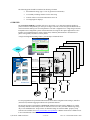
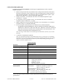
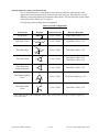
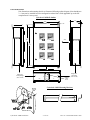
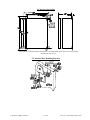
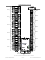
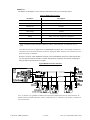
Powersmiths International Corp. 10 Devon Rd. Brampton, ON. L6T 5B5 Toll Free: 1 800 747 9627 Direct Line: 905 791 1493 Fax: 905 791 1493 [email protected] Cyberhawk-100M Installation Bulletin NOTICE SAFETY INSTRUCTIONS ! Use appropriate personal protective equipment and follow safe electrical work practices (eg. NPA 70E) This equipment to be installed and serviced only by qualified competent electrical personnel that have appropriate training on Electrical Systems This device is to be installed in accordance with the prevailing local and National Electric Codes such as National Electric Code (NEC) in the USA or Canadian Electric Code in Canada which governs the requirements for electrical wiring and protection Failure to observe and follow these installation instructions and procedures could result in serious injury or even death RECEIVING The Cyberhawk-100M-XP Multi Power Meter is packaged for shipping in a reinforced cardboard box together with mounting hardware and manuals. CTs and Interface terminals may also be included in the shipment packaged in separate boxes. Unpack and inspect equipment for damage that might have occurred during shipment. Also check the packing list to ensure all the equipment is accounted for (note accessories may be shipped in separate packages). Claims for damages should be made to the carrier immediately and also notify Powersmiths International of the details. Claims for shortages should be made to Powersmiths International at the earliest opportunity. HANDLING The unit weighs about 50 lbs (~ 22kg) which may require two persons to handle it comfortably. Handle the unit in such a way to protect the Displays and avoid rough surfaces that may mar or scratch the surface of the case. STORAGE No special precautions need be taken in storing this device other that it should be protected from moisture or excessive humidity. Storage temperatures should not exceed the limits of – 25 °C to + 60 °C INSTALLATION GUIDELINES The equipment must be installed in accordance with the prevailing local and National Electric Codes such as National Electric Code (NEC) in the USA or Canadian Electric Code in Canada, which governs the requirements for electrical wiring and protection. These requirements will include, but not limited to: Branch circuit protection devices for connection to the voltage bus(es) (not supplied by Powersmiths) Use of an appropriate and approved Current Transformers (CTs) for installation on the current carrying buses (available from Powersmiths on separate order only) Separation of Primary (Voltage Input) and Secondary wiring (CT and Digital Inputs, Communication) Note: This device is not intended as a utility meter or for use ahead of branch-circuit protection Doc. No: 202-001888-607 Rev A00 The following points should be considered in choosing a location: Environmental rating (Type 1 is for dry protected environments) Accessibility including clearance for the door swing Location relative to associated Disconnects and CTs Viewing height for displays OVERVIEW The Cyberhawk-100M-XP is available with 2 to 6 meter ports (‘X’ in XP representing the number of ports). It measures independently per meter port Voltages, Currents, Powers, Energies and Distortions on electrical networks and logs user selected parameters. The unit is supplied in two voltage ranges and with independent user configurable 3-phase measurement Ports for single or three phase applications. It also includes six (6) Digital Inputs for remote contact status, demand synchronization or measurement of pulses from typically Gas, Water or Utility meters. A single line diagram illustrating a basic system hookup is illustrated below. Panel 6 Panel 5 Panel 4 Panel 3 Panel 2 Panel 1 Bus Fused Disconnect Bus Voltage Sensing CT Interface Fused Disconnect CTs Voltage Sensing Current Sensing Current Sensing Pulse Inputs CTs CT Interface It is user programmed for operational characteristics such as Bus Configuration and Voltages, Interfaces (PTs and CTs) and Data Logging described in the operational manual. The unit incorporates a Powersmiths COMSERVER (Ethernet Port with a built in WEB server) (unless specifically omitted at order) that provides for remote user access to all system data and data logs using only a Java enabled Browser. Setup can also be facilitated using one of Powersmiths’ propriety setup software tools available from www.powersmiths.com/cyberhawk. A RS485 connection is available for use in lieu of the Ethernet connection. Cyberhawk-100M Installation - 2 of 18 - Doc. No: 202-001888-607 Rev A00 USER SUPPLIED HARDWARE In addition to the Cyberhawk-100M-XP, the following user supplied hardware will be required to complete installation: Branch circuit protection must be provided for buses (voltage feed) connections, either Fused Disconnects or Breakers, rated 15 Amps or less with an interrupt capacity rating to match bus short circuit rating. Breaker or fuse disconnect must be 3-pole handle tied for 3-phase, 2-pole handle tied for split-phase or 1-pole for single-phase applications. Primary Circuit Wires - UL Listed 600V min. with 75°C minimum temperature Copper conductors 14 – 10 gauge CT Secondary Circuit or Secondary Circuit - UL Listed 600V min. with 75°C minimum temperature Copper conductors 16 – 10 gauge. Ethernet cabling must meet the following requirements: 150 Volts minimum, 75°C minimum temperature rating, Cat 3 minimum, RJ45 Plug CTs for sensing bus currents that have been evaluated for use with this instrument: - INSTRUMENT TRANSFORMERS INC, DIV OF GE MULTILIN. Models 2DARL Series, 5DARL Series, 6ARL Series, 7ARL Series, 8RL Series, 19RL Series, 550L Series, 500L Series, 600L Series, 601L Series, rated min. 600 V. Provided with min. 24 in. leads with min. 1/32 in. insulation, rated minimum 600V, and minimum of 105ºC. Note: CT sizing is based on Bus current and the physical dimensions of the bus; refer to table following: CT Interface Terminal Blocks (Optional) Note: Not required but facilitates CT termination and service. It consists of a set of terminals mounted in an electrical box that provides a convenient termination point for the CT secondary leads close to the CT location and also a means of conveniently shunting (shorting) the CT outputs to facilitate equipment service. CT Selection Table Parameter Requirement Primary CT Rating (current) Equal to current rating of bus or Bus Power Protection Device Primary Voltage Rating 600V min. Secondary Current 5 Amps at nominal current rating Burden 3 VA minimum Ratio Nominal Primary Current: 5 (eg: 1000:5) Window Sized for Bus dimensions UL Listed ANSI/IEEE C57.13 UL746 Compliance UL746C: Standard for Polymeric Materials Wire Leads with minimum specifications as follows: Voltage: 600V minimum Temperature: 105 °C Insulation: 1/32 inch Wire Lead Length: 24” minimum (GE) Instrument Transformers CTs* investigated for use with Manufacturer: Donut Models: 2DARL-xxx; 5DARL-xxx; 6ARL-xxx; this instrument 7ARL-xxx; 8RL-xxx; 19RL-xxx; Rectangular Models: 550-L-yyy x zzz-xxx Split-core Models: 500-L-xxx; 600-L-xxx; 601-L-xxx Note: xxx denotes ratio (e.g. - 501 is 500:5) yyy and zzz denotes window dimensions *Note: These CTs are listed to UL ANSI/IEEE C57.13 and additionally comply with the requirements of UL916 with regard UL746 for polymeric material requirements and secondary lead termination as specified above Secondary Terminations Cyberhawk-100M Installation - 3 of 18 - Doc. No: 202-001888-607 Rev A00 SYSTEM INSTALLATION CONFIGURATIONS Prior to installation make a wiring diagram of the desired connections with reference to the appropriate system configuration to be connected for each meter port. Note that wiring for the different system configurations are illustrated in this bulletin. This will define the system voltage connections and the number of CTs required. The following system configurations are supported: Table of System Configurations System Type Diagram Single Phase A Split Phase 3-Wire N N A B Connection Type Reference Diagrams 2-wire + GND Single Phase 2-Wire; 1-CT 3-wire + GND Split Phase 3-Wire; 2-CT 4-wire + GND Three Phase 4-Wire; 3-CT 3-wire + GND Three Phase 3-Wire; 2-CT Three Phase 3-Wire; 3-CT 3-wire + GND Three Phase 3-Wire; 1-CT 4-wire + GND Three Phase High-Leg; 3-CT 3-wire + GND Three Phase 3-Wire; 2-CT A N Three Phase Wye C B A Three Phase Delta B C Three Phase Delta (Balanced System)* A B C A Three Phase High Leg Delta B N C A Three Phase OpenDelta N B *Note: May only be used on balanced systems where all the phase currents are equal or significant errors will result Cyberhawk-100M Installation - 4 of 18 - Doc. No: 202-001888-607 Rev A00 UNIT DIMENSIONS Unit dimensions and mounting details are illustrated following outline diagram (Note that Meters 3 – 6 may not be installed based on configuration ordered but is field upgradable up to the full complement of 6 meter ports): Cyberhawk-100M-6P Outline 7.9" 15.8" 0.5" 0.8" 14.1" view 6" 25.6" view 6" 23.9" 17" 16" view Wiring access Primary Voltages (Class 1 circuits) 6" 6" 6.5" 3" 6" Network Cable Access Wiring access Low Voltage (Class 2 circuits) Cyberhawk-100M Mounting Brackets Cyberhawk-100M Installation - 5 of 18 - Doc. No: 202-001888-607 Rev A00 CT Interface Box Outline Note that the CT Interface Box illustrated is a recommended option that is used to facilitate installation and service. CT Interface Box Mounting Brackets Cyberhawk-100M Installation - 6 of 18 - Doc. No: 202-001888-607 Rev A00 INSTALLATION WARNING HAZARD OF ELECTRIC SHOCK OR ARC FLASH Open or disconnect all power sources and “Lock out” prior to any work being done on the electrical system More than one disconnect switch may be required to de-energize the equipment before servicing Open or disconnect circuit from power-distribution system (or service) of building before installing or servicing current-sensing transformers (CTs) Never leave CTs in powered circuit open circuited Risk of Electric Shock ! Caution: Do not assume but check that all power sources at the system connection points are off using a properly rated voltage indicating device (Multimeter, etc) and “Locked out” MOUNTING Prior to Installation: Prior to installation check the internal condition of the equipment as follows: Equipment Voltage rating for the application (e.g. 600/480V, 208/120V) Damaged or dislodged or loose components Loose connectors or connections Broken wires Mounting the Cyberhawk-100M-XP Attach the mounting brackets to the Cyberhawk-100M-XP with supplied mounting bracket hardware. One of two types may be supplied as illustrated. Mount the unit to the wall in the required location with ¼” hardware appropriate for the mounting surface material (Note: mounting hole is 5/16”). Mounting the CT Interface Box (if supplied) Attach the wall mounting brackets to the CT Interface Box with supplied mounting bracket hardware as illustrated above Locate and mount the unit to a wall in the required location with ¼” hardware appropriate for the mounting surface material (Note: mounting hole is 5/16”) Note locate the CT Interface Box (if supplied) to allow for direct wire connections (without splices) from the CTs to the terminals in the box. Installation of Branch Circuit Protection Devices Install a Branch Circuit Protection Device (Fused Disconnect or Breaker) for each Bus to be monitored following the specific manufacturer’s instruction and in compliance with the relevant local and national electric codes*. *Reference: NEC 2005 Article 408 Para: 408.52 Cyberhawk-100M Installation - 7 of 18 - Doc. No: 202-001888-607 Rev A00 Installation of Current Transformers WARNING Risk of Electric Shock HAZARD OF ELECTRIC SHOCK OR ARC FLASH To reduce risk of electric shock, always open or disconnect circuit from power-distribution system (or service) of building before installing or servicing current-sensing transformers Considerations: CTs may be installed in Electrical Enclosures, Switchgear, Switchboards, Panel-boards or in auxiliary gutters on the current carrying bus wires under the following code requirements** and considerations: Installation of the CTs within Switchgear, Panel-boards or Gutters shall not reduce the available space to more than 75% of its available volume* *See NEC 2005 Article 312 Para: 312.8 and Article 366 CTs and the secondary wires are to be arranged away from live terminals and the CTs secured to the bus wires using a minimum of three cable ties to prevent movement of the CTs CT secondary wires to be secured in their desired position away from the current carrying bus CT Secondary wires are to be feed in a dedicated conduit installed for the purpose (not common with live bus voltage wires) to the meter or CT Interface Box (if fitted). Note: No splices on the CT secondary wires are permitted within the enclosure where installed or in the conduit through which the secondary wires are run. Splices are only permitted as follows: - Within the CT Interface Box or the Cyberhawk-300/MPC - In a dedicated Auxiliary Gutter or Terminal box Note: Splices must comply with the requirements of the relevant local and national electric codes See NEC 2005 Article 110 Para: 110.14 (B) Installation: Install each CT on the required phases of current carrying bus wires with regard to phase and polarity (see diagram opposite) Note that errors in CT phasing may be corrected later by simply reversing the secondary leads at their termination point. Secure CT secondary wires in their desired position away from the current carrying bus using cable ties Feed the CT Secondary wires through the dedicated conduit installed for the purpose (not common with live bus voltage wires) to the meter or CT Interface Box (if fitted) Note: All CTs are internally grounded at CT negative (-) terminals Cyberhawk-100M-XP Terminal Identification The internal terminals are identified below and are segregated into Class 1 and Class 2 partitions as follows: Class 1 Circuits: Voltage Sensing Inputs Class 2 Circuits: Current Transformer Inputs, Digital Inputs (or Outputs if fitted) Note that this segregation of wiring must be adhered to during installation Cyberhawk-100M Installation - 8 of 18 - Doc. No: 202-001888-607 Rev A00 Terminal Identification and Layout F1-1 L1 + -- Meter 6 L2 F1-2 L3 F1-3 N Meter 5 L1 F1-1 L2 F1-2 L3 F1-3 N Meter 4 L1 F1-1 L2 F1-2 L3 F1-3 N Meter 3 L1 F1-1 L2 F1-2 L3 F1-3 N Meter 2 L1 F1-1 L2 F1-2 L3 F1-3 N F1-1 L2 F1-2 L3 F1-3 12-48V = Meter 1 L1 N GND Power Supply L N G R/T-(A) R/T+(B) COM GND CT1+ CT1CT2+ CT2CT3+ CT3GND CT1+ CT1CT2+ CT2CT3+ CT3GND CT1+ CT1CT2+ CT2CT3+ CT3GND CT1+ CT1CT2+ CT2CT3+ CT3GND CT1+ CT1CT2+ CT2CT3+ CT3GND COM Dig/1 Dig/2 Dig/3 CT1+ CT1CT2+ CT2CT3+ CT3GND COM Dig/1 Dig/2 Dig/3 RS485 Meter 6 Meter 5 Meter 4 Meter 3 Meter 2 Meter 1 RJ45 (Ethernet) Note: CTs are internally grounded at all CT negative (-) terminals Cyberhawk-100M Installation - 9 of 18 - Doc. No: 202-001888-607 Rev A00 SYSTEM WIRING The Cyberhawk-100M-XP is supplied with 3-Port 4-Wire measurement inputs for each meter port (in one of two voltage ranges; 600/480 or 208/120) that may be configured to operate on any of the listed configurations requiring a specific hookup and setup. Internal operating power is derived from the measurement inputs at Meter Port 1 with provision to changing this to Meter Port 2. Wire the unit for each meter port per the relevant local and national electric codes* and the following instructions and with reference to the specific system diagram for the application configuration. * See NEC 2005 Section 200 (Wiring and Protection) Voltage Hookups: Wire each Meter Port Voltage Input through Branch Circuit Protection Devices* (Breaker or Fused Disconnect) rated 15 Amp or less (2 amp minimum) with an interrupt capacity rating to match the bus short circuit rating. This protection device, Breaker of Fuse disconnect, must be 3-pole handle ties for 3phase or 1-pole for single phase applications. *Reference: NEC 2005 Article 408 Para: 408.52 and see notes below: - Wires to be copper conductors 14 – 10 gauge rated 600 Volt minimum with 75 °C minimum temperature rating - Unit must have a grounded conductor wired to the ground terminal - Each ungrounded connector must be ‘fused” including the Neutral if it is not grounded - This wiring must be segregated in the Class 1 wiring compartment separate from the Class 2 circuits - Actual unit load is less than 100mA per phase current - Actual phase rotation is not critical but CTs and the voltage connection must match e.g. CT1 on L1 etc. CT Hookup (Direct): Wire the CT secondaries for each Meter Port through a dedicated conduit (as previously described) to the Cyberhawk-100M-XP observing polarity and ensuring correlation between Voltage and Current inputs. CT Hookup (through optional CT Interface): Wire the CT secondaries through a dedicated conduit (as previously described) to the CT Interface box and terminate at the appropriate terminal observing polarity: Wire the CT secondaries from the other side of the CT Interface terminals to the Cyberhawk100M-XP through a dedicated conduit observing polarity Note: Wires to be copper conductors 16 – 10 gauge rated 600 Volt minimum with 75 °C minimum temperature rating Ethernet Cabling: Cabling to this Port must meet the following requirements: - Ethernet Cabling to be rated 150 Volt minimum with 75 °C minimum temperature rating with a RJ45 termination plug System Wiring Diagrams: The following system wiring diagrams detail the wiring for each Port configuration for direct connection to the system. Nominal system voltages referenced to the two models are as follows: - Cyberhawk-100M-XP-208/120: 240 Volts Line to Line, single or three phase Cyberhawk-100M-XP-600/480: 600 Volts Line to Line, single or three phase Note that connection to Electrical Systems with voltages greater that listed will require the use of Potential Transformers (PT) in the voltage connection (L1, L2, L3 and N) and additionally insulated CTs. Refer to the Manual for more details. Cyberhawk-100M Installation - 10 of 18 - Doc. No: 202-001888-607 Rev A00 Wiring Diagram for Single Phase 2-wire systems CT 5A sec. Fused Disconnect 15A max. Connections for each Meter Port (1 of 2-6) CT Shorting Block CT1+ CT1-- G N L1 Neutral need not be fused if grounded L2 Class1 Circuits L3 Class 2 Circuits CT1+ CT1CT2+ X1 (+) (white) CT2CT3+ Power Flow CT3- G Cyberhawk-100M Use Copper Conductors Only #16 ga. Min. 600V min. 75OC min. Currents < 1A except CTs at < 5A X2 (-) (Black) X1 Load Source Wiring Diagram for Split Phase 3-wire systems Cyberhawk-100M Installation - 11 of 18 - Doc. No: 202-001888-607 Rev A00 Wiring Diagram for three phase 4-wire systems Wiring Diagram for three phase 3-wire systems (2-CT connection) Cyberhawk-100M Installation - 12 of 18 - Doc. No: 202-001888-607 Rev A00 Wiring Diagram for three phase 3-wire systems (3-CT connection) CTs 5A sec. L1 L2 L3 G G CT3-- Connections for each Meter Port (1 of 2-6) CT1+ CT1-CT2+ CT2-CT3+ Fused Disconnect 15A max. CT Shorting Terminal Block N L1 L2 Class1 Circuits L3 Class 2 Circuits CT1+ CT1- X1 (+) (white) CT2+ CT2- Power Flow CT3+ X2 (-) (Black) X1 Load CT3- G Cyberhawk-100M Use Copper Conductors Only #16 ga. Min. 600V min. 75OC min. Currents < 1A except CTs at < 5A Source Wiring Diagram for three phase 3-wire balanced systems (1-CT connection) Cyberhawk-100M Installation - 13 of 18 - Doc. No: 202-001888-607 Rev A00 Wiring Diagram for three phase 4-wire High Leg systems CTs 5A sec. A B C N G Fused Disconnect 15A max. Connections for each Meter Port (1 of 2-6) N CT3-- CT1+ CT1-CT2+ CT2-CT3+ G CT Shorting Terminal Block L1 L2 Class1 Circuits L3 Class 2 Circuits CT1+ CT1CT2+ X1 (+) (white) CT2CT3+ Power Flow CT3- G Cyberhawk-100M Cyberhawk-100M Installation Use Copper Conductors Only #16 ga. Min. 600V min. 75OC min. Currents < 1A except CTs at < 5A - 14 of 18 - X2 (-) (Black) X1 Load Source Doc. No: 202-001888-607 Rev A00 Digital Input Hookups: Two groups of three (3) digital inputs (total of 6 inputs) are included in the Cyberhawk-100M. Typical applications include: Remote contact status (Open/Closed for Breakers etc) Demand Synchronization Tariff steering to different accumulators Pulse counting from external measuring devices such as Gas, Water or Utility meters equipped with non-potential pulse outputs and are scaled (by user setup) for display in appropriate units (M3, kWh, etc) . These are wired based on the user requirements. Table of Digital Input Characteristics Parameter Description Inputs 3 (Dig/1, Dig/2, Dig/3) Bias Voltage 5 VDC Bias Current 10 mA (max.) Impedance 680 ohms Connector Compression; #12 to 18 ga. Wire Location Class 2 segregated compartment Naming User Selected*: kWh, Gas, Water (Cold), Water (Hot) Scaling User programmable Response Time 50ms (max.) External Contact < 100 ohms closed; > 500k ohms open *Note: Dig/1 and Dig/2 may alternatively be used for energy accumulation in up to 4 different registers for selective tariff rates Digital Input Wiring for Pulse Counting (one group shown) Note that wiring for the other group and all other applications is similar using a non-potential contact from the source. Cyberhawk-100M Installation - 15 of 18 - Doc. No: 202-001888-607 Rev A00 COMMUNICATION The Cyberhawk-100M-XP is equipped with a Powersmiths COMSERVER (if not excluded at order) providing an Ethernet connection and a RS485 Port that is normally dedicated for internal use unless disconnected from it to make it available for external use. Ethernet Port 12-48V = The Port is located on the COMSERVER (MOXA UC-7112, located horizontally between the two terminal compartments) shown below at Port LAN1and is connected using a standard Ethernet patch cable fitted with a RJ45 plug. Connection can be to a network or directly to a PC using a cross over patch cable (for IP setup prior to connection to the network); refer to the Powersmiths COMSERVER User Manual for setup instructions downloadable from www.powersmiths.com/cyberhawk under the COMSERVER selection. Table of Ethernet Port Characteristics Parameter Bit rate Connection Isolation Protocols IP Addressing Description 10/100 BaseT RJ45 1,500V TCP/IP, HTTP, Modbus TCP DHCP Client (dynamic and static) Note: Unit shipped with dynamic addressing enabled which may be changed to static at setup. Note: It may be advisable to check with the local IT administrator prior to actually connecting the unit to the network for pre-assignment of Network IP addresses; to this end a crossover cable may be used with a local PC for local setup and is covered in the Manual in the section on communication setup. Cyberhawk-100M Installation - 16 of 18 - Doc. No: 202-001888-607 Rev A00 RS485 Port The RS485* is half-duplex 2-wire connection with characteristics given in the table below. Table of RS485 Characteristics Parameter Description Connections ½ Duplex; (Com (Shield); R/T – (A); R/ T + (B)) Baud Rate 1,200; 2,400; 4,800; 9,600 Transceivers 160 units Addresses 247 Max. Range 1,000 M Connector Compression; 12 to 24 ga. wire Wiring 300V; 75°C; #18 – 24 ga. (Z = 120 ohms) Termination* 120 Ohms (internal), 100 ohm ``soft`` ground Protocol Modbus RTU *Note: To disable internal 120 ohm termination, remove connection from `T` terminal at rear of meter. *Note that when the unit is equipped with a COMSERVER, the RS485 Port is not normally available for external use unless disconnected from it as follows: Unplug the DB-9 connector at P1 located at the rear of the network device (MOXA). Wire the Cyberhawk-100M -XP RS485 terminals to the external RS485 Network by connecting the R/T(A), R/T+(B) and common terminals. Terminate and ground as required per the Network configuration using the diagram provided below as a guide. Typical RS485 Network Connection Note: A 100 ohm `soft` ground is included in the Cyberhawk-100M and an internal 120 termination. To disable internal 120 ohm termination, remove connection from `T` terminal at rear of Meter 1 mounted on the enclosure door. Cyberhawk-100M Installation - 17 of 18 - Doc. No: 202-001888-607 Rev A00 OPERATIONAL CHECKS CAUTION RISK OF ELECTRIC SHOCK CAUTION ! Replace all equipment covers (or doors) prior to powering on Do not attempt any internal service of the power meter Do not touch any electrical terminals; CT inputs may generate dangerous voltages if not properly terminated Refer all servicing only to by qualified competent electrical personnel that have appropriate training in electrical systems Open or disconnect circuit from power-distribution system (or service) of building before any service (e.g. wiring corrections) is attempted Please refer to the manual for full setup and operating instructions: Note previous cautions on consulting with the competent network administrator prior to connecting to the local Ethernet Network. Open CT Shorting Links (if any were installed) Close all equipment covers Power on system Bus Setup the Cyberhawk-100M-XP for each meter following instructions given in the user manual which may be setup locally at the screen or by PC using Powersmiths propriety setup software available at www.powersmiths.com/cyberhawk under the appropriate product selection Observe that the individual meter screens on the Cyberhawk-100M-XP display meaningful data: - Voltages - Currents - Powers (positive not negative) Typical screens relative to the selector switch position is shown below: TH D P- PF Cyberhawk-100M Installation TH D P- PF - 18 of 18 - TH D PPF TH D PPF Doc. No: 202-001888-607 Rev A00