1
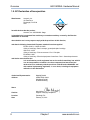
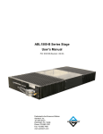
AGS15000HL Series Stage
User’s Manual
Dedicated to the Science of Motion
Aerotech, Inc.
101 Zeta Drive,
Pittsburgh, PA, 15238
Phone: 412-963-7470
Fax: 412-963-7459
www.aerotech.com
Product Registration
Register online at: http://www.aerotech.com/prodreg.cfm
Technical Support
United States Headquarters:
Phone: (412) 967-6440
Fax: (412) 967-6870
Email: [email protected]
United Kingdom:
Phone: +44 118 940 9400
Fax: +44 118 940 9401
Email: [email protected]
Germany:
Phone: +49 911 967 9370
Fax: +49 911 967 93720
Email: [email protected]
Japan:
Phone: +81(0)47-489-1741 (Sales)
Phone: +81(0)47-489-1742 (Service)
Fax: +81(0)47-489-1743
Email: [email protected]
China:
Phone: +852-3793-3488
Email: [email protected]
Revision History
Revision 1.01.00
February 21, 2011
Revision 1.00.00
October 31, 2008
Product names mentioned herein are used for identification purposes only and may be trademarks of
their respective companies.
© Aerotech, Inc. 2011
AGS15000HL Hardware Manual
Table of Contents
Table of Contents
Table of Contents
List of Figures
List of Tables
iii
v
vii
Chapter 1: Overview
1
1.1. Standard Features
1.1.1. Linear Motor / Linear Encoder
1.1.2. Rugged Design
1.1.3. CMS Options
1.1.4. Turnkey Operation
1.2. Optional Features
1.2.1. Additional Axes
1.2.2. Cleanroom Compatability
1.2.3. Electronics / Controller
1.3. Model Numbers
1.4. Safety Procedures and Warnings
1.5. EC Declaration of Incorporation
Chapter 2: Installation
2.1. Unpacking and Handling the Stage
2.2. Mounting the System to a Machine Base
2.3. Attaching the Payload to the Stage
2.4. Electrical Installation
2.5. Air Requirements
Chapter 3: Operating Specifications
3.1. Environmental Specifications
3.2. Load Capability
3.3. Basic Specifications
3.4. Overtravel Safety
Chapter 4: Maintenance
4.1. Service and Inspection Schedule
4.2. Cleaning and Lubrication
4.3. Linear Lubrication and Cleaning Procedure
4.4. Linear Encoder Cleaning and Maintenance Procedure
4.5. System Calibration Procedure
2
2
2
2
2
3
3
3
3
4
6
8
9
9
10
12
12
12
13
13
13
14
16
17
17
17
18
19
20
Appendix A: Warranty and Field Service
21
Appendix B: Technical Changes
23
Appendix C: Payload and Performance Plots
25
Index
27
Reader's Comments
29
www.aerotech.com
iii
Table of Contents
iv
AGS15000HL Hardware Manual
www.aerotech.com
AGS15000HL Hardware Manual
List Of Figures
List of Figures
Figure 2-1:
Figure 4-1:
Figure 4-2:
Compliant Mounting, With and Without Mounting Bolt
Location of Grease Nipples (approximate)
Removing Upper Axis Encoder Cover
www.aerotech.com
10
18
19
v
List of Figures
vi
AGS15000HL Hardware Manual
www.aerotech.com
AGS15000HL Hardware Manual
List of Tables
List of Tables
Table 1-1:
Table 3-1:
Table 3-2:
Table 3-3:
Table B-1:
Table B-2:
Model Numbering System
Environmental Specifications
AGS15000HL Series Specifications
AGS15000HL Motor Specifications
Current Changes (1.01.00)
Archived Changes
www.aerotech.com
4
13
14
15
23
24
vii
List of Tables
viii
AGS15000HL Hardware Manual
www.aerotech.com
AGS15000HL Hardware Manual
Overview
Chapter 1: Overview
The AGS15000HL series of Cartesian gantry systems is designed for ultra-precision contouring capabilities,
providing outstanding performance and versatility in a wide range of automation platforms. To ensure high
contouring accuracy, the bridge’s center of gravity is kept in line with the lower axis bearings and forcers to
minimize pitch and roll errors at the work point.
AGS15000HL systems can be found in production plants around the world, in applications including precision
micromachining, stencil cutting, fuel cell manufacturing, flat sheet processing, high-speed pick-and-place,
automated assembly, vision inspection, dispensing stations, and high-accuracy inspection.
This manual describes Aerotech’s AGS15000HL series positioning gantry. This chapter introduces standard
and optional features of the AGS15000HL, and gives general safety precautions.
N O T E : This manual should be read in its entirety before operating the AGS15000HL system.
www.aerotech.com
Chapter 1
1
Overview
AGS15000HL Hardware Manual
1.1. Standard Features
1.1.1. Linear Motor / Linear Encoder
Aerotech’s high-performance brushless linear servomotors drive the AGS15000HL to speeds up to 3 m/s
and accelerations up to 5 g. Dual linear motors and encoders are included on the lower axis for the highest
level of performance and precision. The rugged noncontact optical linear encoders offer resolutions to 1 nm
when coupled with Aerotech’s encoder multiplier. Optimized to account for thermal expansion, the design
ensures high accuracy under all operating conditions.
1.1.2. Rugged Design
The linear motor is a noncontact device, resulting in no backlash, wear, or maintenance. The bearings are
preloaded linear motion guides with wiper seals and grease fittings, and are mounted to provide optimized
stiffness and load distribution.
1.1.3. CMS Options
Extensive R&D has resulted in an optimized cable management system (CMS) that has been field proven
as the industry’s most reliable design. Large bend radii and high-flex cables ensure that the AGS15000HL
provides millions of cycles of maintenance-free operation. In the unlikely event of a component failure, a modular design ensures that part replacement is fast and easy. The CMS on the AGS15000HL has also been
designed to provide smooth and quiet operation.
All customer cabling and pneumatics can be routed through the system cable management. Connectors are
provided at the workpiece and at the opposite end of the cable management, greatly simplifying final
machine integration.
1.1.4. Turnkey Operation
Aerotech’s years of experience manufacturing precision positioning and control systems can be leveraged
by acquiring a turnkey system. Typical options include Z-theta mechanisms, risers to accommodate automated parts handling equipment, and machine bases that are designed to accommodate the entire controls
and electronics subsystems.
Aerotech manufactures a wide range of high-performance amplifiers and advanced motion controllers that
are optimized for high-performance automation applications.
2
Chapter 1
www.aerotech.com
AGS15000HL Hardware Manual
Overview
1.2. Optional Features
1.2.1. Additional Axes
Additional motion axes can be integrated onto the 2-axis AGS15000HL system. Typically, one or two additional axes (linear or rotary) are integrated onto the carriage of the cross axes. All system alignments and metrology are qualified with these additional axes integrated onto the system. Separate Hardware Manuals will
be provided for additional axes integrated onto the AGS15000HL system.
1.2.2. Cleanroom Compatability
The AGS15000HL can be configured for up to Class 10 cleanroom operation. Standard features for Class 10
cleanroom operation are:
l
Stainless Hardware
l
Custom cable management (depending on the level of cleanroom, a trackless cable carrier may be utilized)
l
Cleanroom grease – refer to section 4.2 for grease specification.
1.2.3. Electronics / Controller
The AGS15000HL is typically part of a complete Aerotech motion control system, which is adjusted at the
factory for optimum performance. Setup usually involves connecting a stage to the appropriate drives with
the cables provided. Refer to your electrical documentation package for further information.
www.aerotech.com
Chapter 1
3
Overview
AGS15000HL Hardware Manual
1.3. Model Numbers
The stage model number indicates the optional features on a particular stage. To determine the options on a
particular stage, refer to the table below.
Example: AGS15-500-500-HL-10X2-10-LT50X5-LT50X5-GR
Table 1-1:
Model Numbering System
AGS15000 Series Linear Motor Gantry
AGS15500-500
500 mm x 500 mm (20 in x 20 in) Cartesian gantry with linear motor, linear encoder, and limits
AGS15750-750
750 mm x 750 mm (30 in x 30 in) Cartesian gantry with linear motor, linear encoder, and limits
AGS1510001000
1000 mm x 1000 mm (40 in x 40 in) Cartesian gantry with linear motor, linear encoder, and
limits
AGSxxxx-yyyy
Other travels available; please consult factory
Loading
-HL
High loading
Motor
-10
Brushless linear motor – BLM-264-A (upper Y-axis only)
-10X2
Dual brushless linear motor – dual BLM-386-A (lower X-axis only)
-10HX2
Dual brushless linear motor – dual BLMH-382-A (lower X-axis only)
Limits
-NC
Normally closed end of travel limit switches (STANDARD)
-NO
Normally open end of travel limit switches
Standard Linear Encoders
-LT50AS
Dual linear encoder for lower axis; amplified sine output; linear encoder for upper axis
-LT50X50
Dual linear encoder for lower axis; 0.1 micron line driver output; linear encoder for upper
axis
-LT75AS
Dual linear encoder for lower axis; amplified sine output; linear encoder for upper axis
-LT75X50
Dual linear encoder for lower axis; 0.1 micron line driver output; linear encoder for upper
axis
-LT100AS
Dual linear encoder for lower axis; amplified sine output; linear encoder for upper axis
-LT100X50
Dual linear encoder for lower axis; 0.1 micron line driver output; linear encoder for upper
axis
Base Plate
4
-GR500-500
Granite baseplate for AGS15500-500
-GR750-750
Granite baseplate for AGS15750-750
-GR1000-1000
Granite baseplate for AGS151000-1000
-GRR500-500
Granite baseplate for AGS15500-500 with 150 mm (6 in) risers
-GRR750-750
Granite baseplate for AGS15750-750 with 150 mm (6 in) risers
-GRR1000-1000
Granite baseplate for AGS151000-1000 with 150 mm (6 in) risers
Chapter 1
www.aerotech.com
AGS15000HL Hardware Manual
Overview
Table 1-1: Model Numbering System (continued)
Accessories (to be ordered as separate line item)
Z100
100 mm (4 in) travel z-stage
Z150
150 mm (6 in) travel z-stage
THETA
360° travel theta axis
MB500-500
Steel weldment machine base for AGS15500-500
MB750-750
Steel weldment machine base for AGS15750-750
MB1000-1000
Steel weldment machine base for AGS1000-10000
www.aerotech.com
Chapter 1
5
Overview
AGS15000HL Hardware Manual
1.4. Safety Procedures and Warnings
The following statements apply throughout this manual. Failure to observe these precautions could result in
serious injury to those performing the procedures and damage to the equipment.
This manual and any additional instructions included with the stage should be retained for the lifetime of the
stage.
To minimize the possibility of electrical shock and bodily injury or death, disconnect all electrical power prior to making any electrical connections.
To minimize the possibility of electrical shock and bodily injury or death when any electrical
circuit is in use, ensure that no person comes in contact with the circuitry when the stage is
connected to a power source.
To minimize the possibility of bodily injury or death, disconnect all electrical power prior to
making any mechanical adjustments.
Moving parts of the stage can cause crushing or shearing injuries. All personnel must
remain clear of any moving parts.
Improper use of the stage can cause damage, shock, injury, or death. Read and understand
this manual before operating the stage.
If the stage is used in a manner not specified by the manufacturer, the protection provided
by the stage can be impaired.
Stage cables can pose a tripping hazard. Securely mount and position all stage cables to
avoid potential hazards.
6
Chapter 1
www.aerotech.com
AGS15000HL Hardware Manual
Overview
Do not expose the stage to environments or conditions outside the specified range of operating environments. Operation in conditions other than those specified can cause damage to
the equipment.
The stage must be mounted securely. Improper mounting can result in injury and damage to
the equipment.
Use care when moving the stage. Manually lifting or transporting stages can result in injury.
Only trained personnel should operate, inspect, and maintain the stage.
This stage is intended for light industrial manufacturing or laboratory use. Use of the stage
for unintended applications can result in injury and damage to the equipment.
Before using this stage, perform an operator risk assessment to determine the needed
safety requirements.
www.aerotech.com
Chapter 1
7
Overview
AGS15000HL Hardware Manual
1.5. EC Declaration of Incorporation
Manufactorer:
Aerotech, Inc.
101 Zeta Drive
Pittsburgh, PA 15238
USA
herewith declares that the product:
Aerotech, Inc. AGS15000HL Stage
is intended to be incorporated into machinery to constitute machinery covered by the Directive
2006/42/EC as amended;
does therefore not in every respect comply with the provisions of this directive;
and that the following harmonized European standards have been applied:
EN ISO 12100-1,-2:2003+A1:2009
Safety of machinery - Basic concepts, general principles for design
ISO 14121-1:2007
Safety of machinery - Risk assessment - Par 1: Principles
EN 60204-1:2005
Safety of machinery - Electrical equipment of machines - Part 1: General requirements
and further more declares that
it is not allowed to put the equipment into service until the machinery into which it
is to be incorporated or of which it is to be a component has been found and
declared to be in conformity with the provisions of the Directive 2006/42/EC and
with national implementing legislation, i.e. as a whole, including the equipment
referred to in this Declaration.
Authorized Representative:
Address:
Manfred Besold
AEROTECH GmbH
Süd-West-Park 90
D-90449 Nürnberg
Name:
Position:
Location:
Date:
8
Alex Weibel /
Engineer Verifying Compliance
Pittsburgh, PA
February 21, 2011
Chapter 1
www.aerotech.com
AGS15000HL Hardware Manual
Installation
Chapter 2: Installation
This chapter describes the installation procedure for the AGS15000HL series gantry, including handling the
stage properly, preparing the mounting surface to accept the stage, securing the stage to the mounting surface, attaching the payload, and making the electrical connections.
Installation must follow the instructions in this chapter. Failure to follow these instructions
could result in injury and damage to the equipment.
2.1. Unpacking and Handling the Stage
Carefully remove the system from the protective shipping container. The AGS15000HL system is supplied
on a granite base plate. An additional system base (typically steel) may also be included with the system. A
fork truck is recommended as a means of moving the system. If there is no system base, or if the system
must be moved independently of its base for any reason, always use a piece of wood or similar material
between the forks and the granite. Use compressed nitrogen or clean, dry air to remove any dust or debris
that has collected during shipping. If any damage has occurred during shipping, report it immediately.
Before operating the stage, it is important to let the stage stabilize at room temperature for at least 12 hours.
Allowing the stage to stabilize to room temperature will help to ensure that all of the alignments, preloads, and
tolerances are the same as they were when tested at Aerotech.
Each stage has a label listing the system part number and serial number. These numbers contain information
necessary for maintaining or updating system hardware and software. Locate this label and record the information for later reference.
Improper stage handling could adversely affect the stage’s performance. Use care when
moving the system. Manually lifting or transporting stages can result in injury.
www.aerotech.com
Chapter 2
9
Installation
AGS15000HL Hardware Manual
2.2. Mounting the System to a Machine Base
If the system was shipped with a machine base, remove the red shipping brackets before using the system.
Level the base plate by adjusting the leveling feet on the machine base. If the system is to be placed on a
base after delivery, it is important to do so properly for optimal performance. It should be supported in three or
four places unless otherwise specified during the system approval process. A compliant mounting scheme
(shown in Figure 2-1) is recommended for most cases. Consult with Aerotech to ensure that this method is
acceptable for a specific application.
For compliant mounting, the machine base mounting surfaces should be coplanar within 0.25 mm (.010 in). A
compliant material at least 6 mm (0.25 in) thick should be inserted between the base and granite base plate
(contact Aerotech for recommended materials). Mounting screws may be used if extra security is desired
between the base plate and machine base. If they are used, compliant washers should be placed under the
screw heads. Tighten screws only ¼ to ½ turn past “finger tight”, using a generous amount of a thread-locking compound to keep the screws in place. This compliant mounting method allows for small height differences between mounting surfaces, thermal expansion mismatch due to different base plate and machine
base materials, and also provides vibration isolation between the floor and the gantry system. If a compliantly mounted system is to be transported, the base plate should be rigidly attached to the machine base during shipping.
Figure 2-1:
Compliant Mounting, With and Without Mounting Bolt
When a system requires extremely high accuracy or ground vibrations are especially prominent, a more complex isolation system may be necessary. Air isolation may be used but is only recommended for systems
with relatively low dynamics. An active isolation system may achieve the same results and can be used for
systems with higher dynamics. Aerotech can supply system properties that may help in sizing these specialized systems.
If relative motion between the gantry system and machine base is absolutely unacceptable for a given application, hard mounting may be necessary. Mounting tolerances, thermal mismatch, and environmental vibrations must be considered when designing a hard mounting scheme. If these issues are not addressed
properly, the base plate may become distorted and affect system performance. Contact Aerotech to determine whether system specifications can be guaranteed with a specific mounting method.
10
Chapter 2
www.aerotech.com
AGS15000HL Hardware Manual
Installation
The stage must be mounted securely. Improper mounting can result in injury and damage to
the equipment.
www.aerotech.com
Chapter 2
11
Installation
AGS15000HL Hardware Manual
2.3. Attaching the Payload to the Stage
To prevent damage to the stage or parts, test the operation of the stage before any fixturing or customer
equipment is integrated onto the system. Proceed with the electrical installation and test the motion control
system.
After testing, a payload may be attached to the upper axis carriage face. The payload must have a mounting
surface that is flat within .013 mm (.0005 in) to prevent distortion of the carriage. If a payload is to be
attached at any other point on the gantry, contact Aerotech for flatness requirements.
2.4. Electrical Installation
Aerotech motion control systems are adjusted at the factory for optimum performance. The AGS15000HL
stage is typically part of a complete Aerotech motion control system; setup involves connecting a stage to
the appropriate drives with the cables provided.
Connect the provided cables to the motor and feedback connectors on the stage. Labels on the drive indicate
the appropriate connections. Refer to your drive manuals and documentation for additional installation and
operation information. In some cases, if the system is uniquely configured, a drawing showing system interconnects is supplied.
Never connect or disconnect any electrical component or connecting cable while power is
applied, or serious damage may result.
The stage's protective ground is located on the motor power connector. This ground must be
connected to a ground connection (the cables provided by Aerotech will create this connection).
2.5. Air Requirements
It is recommended that air cooling be utilized for the linear motors if duty cycle, speeds, and/or accelerations
are high. Consult an Aerotech applications engineer to determine if air cooling is required or recommended
for a specific application. The air requirements are dependent on the system specifications (cleanliness,
etc).
N O T E : For Cleanroom applications, clean, dry nitrogen is recommended since the motor cooling
exhausts into the work area. Recommended specifications for Nitrogen are 99.99% pure and filtered to 0.25
microns.
N O T E : When operating the AGS15000HL it is recommended that 20 psig air be available at the motor
inlet for adequate cooling.
12
Chapter 2
www.aerotech.com
AGS15000HL Hardware Manual
Operating Specifications
Chapter 3: Operating Specifications
The surrounding environment and operating conditions can affect the performance and service life of the
stage. This chapter provides information on ideal environmental and operating conditions. Also included are
instructions for estimating load and torque required to turn the ballscrew given various loadings.
3.1. Environmental Specifications
The environmental specifications for the AGS15000HL are listed in the following table.
Table 3-1:
Environmental Specifications
Ambient
Temperature
Operating: 16° to 25° C (61° to 77° F)
The optimal operating temperature is 20° C ±2° C (68° F ±4° F). If at any time the operating temperature deviates from 20° C degradation in performance could occur. Contact Aerotech for
information regarding your specific application and environment.
Storage: 0° to 40° C (32° to 104° F) in original shipping packaging
Humidity
Operating: 40 percent to 60 percent RH
The optimal operating humidity is 50 percent RH.
Storage: 30 percent to 60 percent RH, non-condensing in original packaging
Altitude
Operating: 0 to 2,000 m (0 to 6,562 ft) above sea level
Contact Aerotech if your specific application involves use above 2,000 m or below sea level.
Vibration
Use the system in a low vibration environment. Excessive floor or acoustical vibration can affect
stage and system performance. Contact Aerotech for information regarding your specific application.
Dust Exposure
The AGS15000HL stages are not suited for dusty or wet environments. This equates to an
ingress protection rating of IP00.
Use
Indoor use only
Do not expose the stage to environments or conditions outside the specified range of operating environments. Operation in conditions other than those specified can cause damage to
the equipment.
3.2. Load Capability
The AGS15000HL is designed for a multitude of applications. The maximum load on the upper axis of the system is 40 kg. This weight of all additional axes integrated onto the system as well as all customer fixturing
and/or test equipment contributes to this load. The load capacity is reduced if the load must be cantilevered
away from the face of the upper axis. Contact Aerotech to determine acceptable loading limits for offset payloads.
The performance of the AGS15000HL will be affected by large payloads. See Appendix C: Payload and Performance Plots to see how the accelerations of each axis are affected by payload.
N O T E : Contact Aerotech directly if load requirements exceed those agreed upon during system approval.
www.aerotech.com
Chapter 3
13
Operating Specifications
AGS15000HL Hardware Manual
3.3. Basic Specifications
Basic specifications are given in Table 3-2 and motor specifications are given in Table 3-3.
Table 3-2:
AGS15000HL Series Specifications
Basic Model
Total Travel
Drive System(1)
AGS15000-500500
500 mm x 50
mm
(20 in x 20 in)
AGS15000-750750
750 mm x 750
mm
(30 in x 30 in)
AGS15000-10001000
1000 mm x 1000
mm
(40 in x 40 in)
AGS15000-12501250
1250 mm x 1250
mm
(50 in x 50 in)
Lower Axis
Linear Brushless Servomotor — Dual BLM-386-A or Dual BLMH-382-A
Upper Axis
Linear Brushless Servomotor — BLM-264-A
Bus Voltage
Up to 340 VDC
Feedback
Noncontact Linear Encoder
Resolution(2)
0.001 µm - 1.0 µm (0.04 µin - 40 µin)
Maximum Travel
Speed (3)
3 m/s (120 in/s)
Maximum Linear Acceleration
5 g (50 m/s2) (no-load)
Maximum Load (4)
40.0 kg (88.2 lb)
Accuracy(5,6)
±1.5 µm (±60
µin)
±2.0 µm (±80
µin)
±2.5 µm (±100
µin)
±3.0 µm (±120
µin)
Repeatability
±0.5 µm (±20
µin)
±0.75 µm (±30
µin)
±1.0 µm (±40 µin)
±1.25 µm (±50
µin)
62.0 kg
72.3 kg
Orthogonality
Moving
Mass
5 arc sec
Lower Axis
Upper Axis
92.7 kg
7.2 kg
Material
Finish
82.5 kg
Aluminum
Stage
Black Anodize; ESD Optional
Carriage
Hard Coating; ESD Optional
(1) Air cooling options available.
(2) With encoder multiplier.
(3) Maximum speed based on stage capability; maximum application velocity may be limited by system data rate and system resolution.
(4) Maximum load based on bearing capability; maximum application load may be limited by acceleration and dynamic requirements.
(5) Measured at center of travel, single axis under static conditions.
(6) Available with Aerotech controllers with HALAR.
14
Chapter 3
www.aerotech.com
AGS15000HL Hardware Manual
Table 3-3:
Operating Specifications
AGS15000HL Motor Specifications
Model
Winding Designation
Performance Specifications (1,5)
Continuous Force, 20 psi, 1.4 bar (2)
Continuous Force, No Cooling, (2)
Peak Force (3)
Electrical Specifications
BLM-386
-A
BLMH-382
-A
233.8
308.2
548.8
N
lb
52.6
69.3
123.4
N
152.9
199.4
357.9
lb
34.4
44.8
80.5
N
935.4
1232.8
2195.0
lb
210.3
277.2
493.5
V / m / sec
34.46
52.10
45.71
V / in / sec
0.88
1.32
1.16
(5)
BEMF Constant (line to line, max)
Continuous Current, 20 psi, 1.4 bar
(2)
Continuous Current, No Cooling
Peak Current, Stall
BLM-264
-A
(2)
(3)
Force Constant, Sinusoidal Drive
(4,8)
Motor Constant (2,4)
Resistance, 25 °C (line to line)
Inductance (line to line)
A, pk
7.80
6.80
13.80
A, rms
5.52
4.81
9.76
A, pk
5.10
4.40
9.00
A, rms
3.61
3.11
6.36
A, pk
31.20
27.20
55.20
A, rms
22.06
19.23
39.03
N / A, pk
29.98
45.33
39.77
lb / A, pk
6.74
10.19
8.94
N / A, rms
42.40
64.10
56.24
lb / A, rms
9.53
14.41
12.64
N / √W
12.71
15.64
23.19
lb / √W
2.86
3.52
5.21
Ohms
5.3
8.0
2.8
mH
4.20
6.20
1.80
Thermal Resistance, 20 psi, 1.4 bar
°C / W
0.30
0.26
0.18
Thermal Resistance, No Cooling
°C / W
0.69
0.61
0.42
VDC
340
340
340
Maximum Bus Voltage
(1) Performance is dependent upon heat sink configuration, system cooling conditions, and ambient temperature
(2) Values shown @ 100 °C rise above a 25 °C ambient temperature, with motor mounted to the specified aluminum heat sink
(3) Peak force assumes correct rms current, consult Aerotech
(4) Force Constant and Motor Constant specified at stall
(5) All performance and electrical specifications +/- 10%
(6) Maximum winding temperature is 125 °C
(7) Ambient operating temperature range: 0 °C - 25 °C, consult Aerotech for performance in elevated ambient temperatures
(8) All Aerotech amplifiers are rated Apk; use torque constant in N-m / Apk when sizing
www.aerotech.com
Chapter 3
15
Operating Specifications
AGS15000HL Hardware Manual
3.4. Overtravel Safety
Each AGS15000HL is designed to operate at certain speeds and accelerations that are unique to that system. The gantry is designed to prevent damage to itself and injury to the operator when used as specified
upon system approval. If any combination of payloads, speeds, and accelerations are to be used other than
those originally approved, contact Aerotech. Do not attempt to modify the system in any way that would
affect overtravels or hard stops.
Attaching larger payloads or using higher speeds and/or accelerations than those specified
during system approval may cause damage to the system or injury to the operator.
Modifying the AGS15000HL in any way that affects overtravels or hard stops may cause
serious system damage or injury to the operator and will void the stage warranty.
16
Chapter 3
www.aerotech.com
AGS15000HL Hardware Manual
Maintenance
Chapter 4: Maintenance
This chapter will cover information about component replacement, intervals between lubrications, detail the
lubrication and inspection process, and cover which lubricants are recommended for use.
To minimize the possibility of bodily injury, confirm that all electrical power is disconnected
prior to making any mechanical adjustments.
The AGS15000HL linear bearing area must be kept free of foreign matter and moisture; otherwise the performance and life expectancy of the stage will be reduced.
4.1. Service and Inspection Schedule
Lubricant inspection and replenishment in AGS15000HL series stages depends on conditions such as duty
cycle, speed, and the environment. An inspection interval of once every few months is recommended until a
trend develops for the application. Longer or shorter intervals may be required to maintain the film of lubricant
on the bearing surfaces. In general, it is recommended that stages operating in a clean environment be lubricated annually. For stages operating under conditions involving excessive debris, lubrication every 3-6
months is recommended. If the system is being operated at a high duty cycle, it is recommended that the
bearings be lubricated after 10,000 km of operation.
4.2. Cleaning and Lubrication
The bearings of the AGS15000HL are generally greased with BR2-Plus grease (supplier is Dow Corning).
http://www.dowcorning.com/applications/search/default.aspx?R=3178EN. Other greases may be used for
cleanroom or other special applications. Contact Aerotech for confirmation on what grease is used in a particular system.
There is one grease nipple per bearing block, for a total of 8 grease points (See Figure 4-1). The grease nipples are type PB1021B for the upper axis and type B-M6F for the lower (supplied by THK). A type N grease
gun fitting should be used for the upper axis bearings and type B for the lower axis bearings (also supplied by
THK). http://www.thk.com.
If a solvent is necessary for cleaning the stage, it is recommended that isopropyl rubbing alcohol be used.
Harsher solvents, such as acetone, may damage the plastic and rubber seals on the linear bearing trucks.
www.aerotech.com
Chapter 4
17
Maintenance
AGS15000HL Hardware Manual
4.3. Linear Lubrication and Cleaning Procedure
The lubrication and cleaning process is outlined in the steps that follow. Before beginning lubrication, see
Section 4.2. for recommended lubricants.
To minimize the possibility of bodily injury, confirm that all electrical power is disconnected
prior to making any mechanical adjustments.
1. Remove power to the stage.
2. Remove any dirty or dried lubricant from the linear bearing guides. Use a clean, lint-free cloth. A swab
soaked in isopropyl alcohol may be used to remove stubborn debris.
3. Apply a thin, continuous film of lubricant to the linear bearing guides. A good quality, natural bristle artist's brush makes an excellent applicator.
4. Using a grease gun with the appropriate fittings (see Section 4.2. ) add lubricant into the grease nipples
of the bearing blocks. All grease nipples are accessible without removal of any components (total qty. 8,
see Figure 4-1). Add lubricant until a small amount can be seen coming out of the bottom of the bearing
block. If extra lubricant spills onto adjacent surfaces, it may be wiped off with a clean cloth.
5. Manually move the stage to the opposite end of travel to work the grease into the linear bearing guides.
6. Repeat steps 3 through 5 for any areas covered by the original table position.
7. Restore power to the stage and drive the stage table back to its original position to redistribute lubricants.
Figure 4-1:
18
Location of Grease Nipples (approximate)
Chapter 4
www.aerotech.com
AGS15000HL Hardware Manual
Maintenance
4.4. Linear Encoder Cleaning and Maintenance Procedure
The AGS15000 system utilizes a high precision, non-contact optical feedback device. Depending on the system environment, the encoder scale may need to be cleaned to ensure optimal encoder signal and system performance.
To minimize the possibility of bodily injury, confirm that all electrical power is disconnected
prior to making any mechanical adjustments.
1. Remove power to the stage.
2. Remove the upper axis encoder cover (multiple pieces) to access the linear encoder scale.
Figure 4-2:
Removing Upper Axis Encoder Cover
3. Carefully clean the linear encoder scale using IPA and a swab, being sure to wipe the swab in the direction of the encoder grating (vertically). Allow the IPA to air dry completely prior to restoring power to the
system.
DO NOT use an aggressive solvent (such as Acetone or similar) to clean the linear encoder
as this may cause damage to the encoder scale.
4. Re-assemble any covers that were removed in Step 3.
5. Restore power to the stage and drive the system through travel to ensure proper encoder signal feedback.
www.aerotech.com
Chapter 4
19
Maintenance
AGS15000HL Hardware Manual
4.5. System Calibration Procedure
If the HALAR option was purchased with the system, then the system was calibrated at the Aerotech factory to meet catalog accuracy and repeatability specifications. The parameter file provided with the system
includes the calibration data for the axes and should be enabled in the controller in order to achieve the specified system accuracy. Other than thermal effects (see Section 0.1.), it is not anticipated that the accuracy
will need to be re-calibrated in the field unless one of the following conditions occur:
l
Shipping damage
If any damage has occurred during shipping, report it immediately.
l
Mechanical crash of the system due to system fault or programming error.
If a mechanical crash of the system has occurred, report it immediately. Aerotech can
assist in determining if any system damage has occurred.
l
20
Field replacement or adjustment of the linear encoder scale or encoder read head.
Chapter 4
www.aerotech.com
AGS15000HL Hardware Manual
Warranty and Field Service
Appendix A: Warranty and Field Service
Aerotech, Inc. warrants its products to be free from defects caused by faulty materials or poor workmanship for a minimum period of one year from date of shipment
from Aerotech. Aerotech's liability is limited to replacing, repairing or issuing credit,
at its option, for any products that are returned by the original purchaser during the
warranty period. Aerotech makes no warranty that its products are fit for the use or
purpose to which they may be put by the buyer, where or not such use or purpose
has been disclosed to Aerotech in specifications or drawings previously or subsequently provided, or whether or not Aerotech's products are specifically
designed and/or manufactured for buyer's use or purpose. Aerotech's liability or
any claim for loss or damage arising out of the sale, resale or use of any of its products shall in no event exceed the selling price of the unit.
Aerotech, Inc. warrants its laser products to the original purchaser for a minimum
period of one year from date of shipment. This warranty covers defects in workmanship and material and is voided for all laser power supplies, plasma tubes and
laser systems subject to electrical or physical abuse, tampering (such as opening
the housing or removal of the serial tag) or improper operation as determined by
Aerotech. This warranty is also voided for failure to comply with Aerotech's return
procedures.
Laser Products
Claims for shipment damage (evident or concealed) must be filed with the carrier
Return Procedure
by the buyer. Aerotech must be notified within (30) days of shipment of incorrect
materials. No product may be returned, whether in warranty or out of warranty, without first obtaining approval from Aerotech. No credit will be given nor repairs made
for products returned without such approval. Any returned product(s) must be
accompanied by a return authorization number. The return authorization number
may be obtained by calling an Aerotech service center. Products must be returned,
prepaid, to an Aerotech service center (no C.O.D. or Collect Freight accepted).
The status of any product returned later than (30) days after the issuance of a
return authorization number will be subject to review.
After Aerotech's examination, warranty or out-of-warranty status will be determined. If upon Aerotech's examination a warranted defect exists, then the product(s) will be repaired at no charge and shipped, prepaid, back to the buyer. If the
buyer desires an airfreight return, the product(s) will be shipped collect. Warranty
repairs do not extend the original warranty period.
Returned Product Warranty Determination
After Aerotech's examination, the buyer shall be notified of the repair cost. At such Returned Product
time, the buyer must issue a valid purchase order to cover the cost of the repair and Non-warranty Deterfreight, or authorize the product(s) to be shipped back as is, at the buyer's
mination
expense. Failure to obtain a purchase order number or approval within (30) days of
notification will result in the product(s) being returned as is, at the buyer's expense.
Repair work is warranted for (90) days from date of shipment. Replacement components are warranted for one year from date of shipment.
At times, the buyer may desire to expedite a repair. Regardless of warranty or outof-warranty status, the buyer must issue a valid purchase order to cover the added
rush service cost. Rush service is subject to Aerotech's approval.
www.aerotech.com
Appendix A
Rush Service
21
Warranty and Field Service
AGS15000HL Hardware Manual
On-site Warranty If an Aerotech product cannot be made functional by telephone assistance or by
Repair sending and having the customer install replacement parts, and cannot be returned
to the Aerotech service center for repair, and if Aerotech determines the problem
could be warranty-related, then the following policy applies:
Aerotech will provide an on-site field service representative in a reasonable amount
of time, provided that the customer issues a valid purchase order to Aerotech covering all transportation and subsistence costs. For warranty field repairs, the customer will not be charged for the cost of labor and material. If service is rendered at
times other than normal work periods, then special service rates apply.
If during the on-site repair it is determined the problem is not warranty related, then
the terms and conditions stated in the following "On-Site Non-Warranty Repair"
section apply.
On-site Non-warranty If any Aerotech product cannot be made functional by telephone assistance or purRepair chased replacement parts, and cannot be returned to the Aerotech service center
for repair, then the following field service policy applies:
Aerotech will provide an on-site field service representative in a reasonable amount
of time, provided that the customer issues a valid purchase order to Aerotech covering all transportation and subsistence costs and the prevailing labor cost, including travel time, necessary to complete the repair.
Company Address Aerotech, Inc.
101 Zeta Drive
Pittsburgh, PA
15238-2897
22
Phone: (412) 963-7470
Fax: (412) 963-7459
Appendix A
www.aerotech.com
AGS15000HL Hardware Manual
Technical Changes
Appendix B: Technical Changes
Table B-1:
Current Changes (1.01.00)
Section(s) Affected
Section 1.5.
General Information
Section added
Section 3.1.
Section added
Chapter 2: Installation, Section 2.1. , Section 2.2. ,
and Section 1.4.
Section 3.3.
www.aerotech.com
Safety information and warnings added
Specifications tables added
Appendix B
23
Technical Changes
Table B-2:
Revision
1.00.00
24
AGS15000HL Hardware Manual
Archived Changes
Section(s) Affected
--
General Information
New manual
Appendix B
www.aerotech.com
AGS15000HL Hardware Manual
Payload and Performance Plots
Appendix C: Payload and Performance Plots
Upper Axis Acceleration Plot:
www.aerotech.com
Appendix D
25
Payload and Performance Plots
AGS15000HL Hardware Manual
Lower Axis Acceleration Plots:
AGS15000HL with BLM motors:
AGS15000HL with BLMH motors:
26
Appendix D
www.aerotech.com
Index
AGS15000HL Hardware Manual
Index
W
Warnings
A
Air Requirements
12
Attaching the Payload
12
6
C
cable
3, 12
Cleaning
17
D
Declaration of Incorporation
8
E
Electrical Installation
12
Environmental Specifications
13
L
Load Capability
13
Lubrication
17
lubrication schedule
17
M
Model Numbers
4, 9
Mounting the System to a Machine Base
10
O
Optional Features
3
Overtravel Safety
16
S
safety procedures
6
Specifications
14
Standard Features
2
U
Unpacking and Handling the Stage
www.aerotech.com
9
Index
27
AGS15000HL Hardware Manual
28
Index
Index
www.aerotech.com
Reader's Comments
AGS15000HL Series Stage Manual
P/N: EDS138, February 21, 2011
Revision 1.01.00
Please answer the questions below and add any suggestions for improving this document.
Is the manual:
Yes
No
Adequate to the subject
Well organized
Clearly presented
Well illustrated
How do you use this document in your job? Does it meet your needs? What improvements, if any, would you
like to see? Please be specific or cite examples.
Stage/Product Details
Name
Model #
Title
Serial #
Company Name
Date Shipped
Address
Customer Order #
Aerotech Subsidiary
Order #
Email
Mail your comments to:
Fax to:
Aerotech, Inc.
101 Zeta Drive
Pittsburgh, PA
15238 U.S.A.
412-967-6870
Email:
[email protected]