1
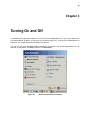
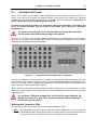
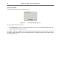
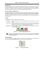
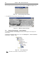
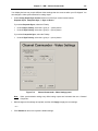
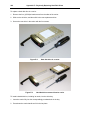
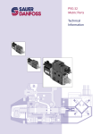
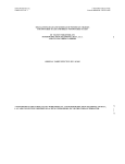
Independence® IDX 4000 Image Generator User Manual Operating Your Independence Image Generator Quantum3D, Inc. 6330 San Ignacio Avenue San Jose, CA 95119-1209 USA Telephone Facsimile General Support (408) 361-9999 (408) 361-9980 http://www.quantum3d.com http://www.quantum3d.com/support 0H 1H Part No. 700-0832-01 IDX Platform Release 4.15 Document Release 1.2 December 17, 2008 Copyright © 2008 Quantum3D, Inc. All rights reserved. All trademarks are the property of their respective owners. 39 Chapter 3 3 Turning On and Off You should always take proper steps to turn on and off your Independence IG. If you remove power from your Independence IG while it is turning off, file corruption might occur. Turning off the Independence IG properly is very simple and performed entirely from the IGC. You can use any of the standard Windows shutdown commands to turn off the Independence IG. For example, on the taskbar, click Start, and then click Shut Down. Figure 3-1 Start menu Shut Down command 40 Chapter 3 – Turning On and Off Alternatively, you can press CTRL+ALT+DEL, and when the Windows Security dialog box appears, click Shut Down. Figure 3-2 Windows Security dialog box The IGC will turn off all the other IGU computers in the Independence IG. After the other IGU computers have turned off, it then starts its own shutdown process. After the IGC turns off, other component systems will remain on. To turn off these systems, turn off the power. 3.1 Turning Off AC Power 48B Confirm that the IGC and all IGU computers have been turned off. The power LEDs (Light Emitting Diodes) associated with each system should be off; the power LEDs are labeled with a light bulb icon. To turn off power to the Independence IG, use the AC power on/off switch at the front-bottom-left of the primary and auxiliary cabinets. After turning off the system, wait a minimum of one minute before turning on the power again with the AC power on/off switch. Figure 3-3 AC power on/off switch located at the front-bottom-left of each cabinet Chapter 3 – Turning On and Off 3.2 41 Turning On AC Power 49B To turn on AC power, use the switch at the front-bottom-left of each cabinet, as shown in Figure 3-3 above. If you have both a primary and auxiliary cabinet, ensure that the two cabinets are grounded together with the chassis ground cable provided in the auxiliary cabinet accessory box. Always turn on power to the auxiliary racks first and the primary rack last. 678H 679H Overload circuit protection breakers are provided for manual on/off switching. The breakers will trip in an overload condition. They are located in the bottom rear of the rack on the power distribution unit. You must wait a minimum of one minute before turning on the power with the AC power on/off switch after turning off the system. First, turn on AC power to any auxiliary cabinets associated with your Independence IG configuration. Then, turn on AC power to the primary cabinet. After AC power has been applied, the IGC, Channel Compositor(s), and IGUs power on automatically. Figure 3-4 Image Generator Controller (IGC) – front panel Your IGC is configured to turn on when you turn power on using the front panel on/off switch. Also, the IGC must have been turned off properly or it may not turn on automatically when you apply power to the rack. If the IGC does not turn on automatically, press the IGC power button. When power is applied to the system, the green power indicator LED will light up. Wait for the IGC to start. When the IGC presents you with the logon screen, log on to Windows. The IGC displays a progress indicator as the system turns on. Let the initialization process finish before using the Independence IG. Do not leave a USB drive plugged into an IGU while it starts. Windows will assign drive letter D to your drive and the automatic network mapping of drive D onto the IGC will fail. Working with Channels or IGUs 108B You can only turn off or turn on the entire IG, not individual channels or IGUs. Note The Independence IG requires that the IGUs be turned off using the IGC. If you turn off power to an individual system using its power button, the system will not turn on automatically the next time you start your IG, and you will have to turn it on manually using its power button. 42 Chapter 3 – Turning On and Off This page concludes Turning On and Off. 83 Chapter 7 7 IGM – Channel Commander Use the Channel Commander to perform tasks with individual channels. In some cases, you also can control individual IGUs. Under the Channel Commander, when you select a channel, (e.g. Channel A) you gain access to the tools and utilities you can use to configure and control that particular channel without affecting the other channels comprising the IG. Many of the functions at the Channel Commander level can be performed at the IG Commander level, but are duplicated here for your convenience. 7.1 Channel Commander – Health & Status 63B The Channel Commander Health & Status panel provides: Version information for the IGUs that make up your Independence IG. Functional tests to verify the integrity of your Independence IG. To display the Health & Status panel, click the node under IG Management → Channel Commander → Channel Name → Health & Status. Figure 7-1 Health & Status access 84 Chapter 7 – IGM – Channel Commander The Channel Commander - Health & Status panel appears: Figure 7-2 Channel Commander - Health & Status panel View Subchannel Information 148B To select a system, under System Selection, click the desired option button. The Health & Status panel contents update. Click Refresh View to update the panel manually. Different IGU types display different types of information. Some information items may not apply for some channel types. Use the System Selection option buttons to check the consistency of component versions among the IGUs that make up the channel. Chapter 7 – IGM – Channel Commander 85 Test 3D Graphics 149B The Channel Commander Test 3D Graphics feature provides an excellent method for isolating rendering problems on a per-IGU basis. If there are problems rendering graphics on a channel, test the 3D graphics for that channel. To test 3D graphics: 1. In the Test 3D Graphics group box, click the Test 3D Graphics button to start a test application. The 3D graphics test displays a spinning Quantum3D logo and status information for the following: Resolution and refresh rate OpenGL version Frame update rate Swap domain Color depth Swap modulo Enhanced sync state Effective FSAA Channel name Anisotropic filtering state Graphics adapter IGUs used to render the image By default, the test runs on all IGUs in the channel. The tests are launched asynchronously on all IGUs, and the spinning logo on each IGU may appear out of phase with the others. 2. Click Terminate Testing to quit the test. Figure 7-3 Test 3D Graphics group box To isolate a bad renderer: 3. Clear the On all IGUs (startup not synchronized) check box 4. Click Test 3D Graphics to run the test only on the IGU selected under System Selection. The Image Quality setting for the Channel and the number of IGUs per channel determines how the output is displayed. 5. To continue to add IGUs to the test, under System Selection, select another IGU, and then click Test 3D Graphics without terminating the previous test. Note From the Channel Commander level, use the controls in the Test 3D Graphics group box to isolate a problem on a particular IGU. To isolate a problem between channels, run this test from the IG Commander level. 86 Chapter 7 – IGM – Channel Commander IGU Commands 150B The IGU Commands enable you to identify an IGU. Figure 7-4 IGU Commands group box To locate a particular IGU in the rack: Click Identify IGU to toggle an nVSync LED between its current color and amber multiple times. The flashing LED identifies the particular IGU. The nVSync LED that is toggled is next to the nVSync cable connections at the back of the IGU. When the nVSync cable is plugged in, and the networking chain is connected correctly, the LED glows green, otherwise it glows red. Chapter 7 – IGM – Channel Commander 7.2 87 Channel Commander – Application Management 64B The Application Management panel simplifies the task of running applications on the Independence IG. This panel provides file browser access to your executable applications. You can start different applications or provide different command parameters on channels that have different role types. Note IGM’s command line interface, Q3dlgmCmd, provides comparable functionality for starting applications on different channels. For more information, see Chapter 9, “ IGM Scripting”. 727H 728H To display the Application Management panel, click the node under IG Management → Channel Commander → Channel Name → Application Management. Figure 7-5 Application Management access 88 Chapter 7 – IGM – Channel Commander The Channel Commander - Application Management panel appears: Figure 7-6 Channel Commander - Application Management panel The Application Management panel has two distinct areas: Run On IGC. This area is only associated with the IGC. Use its command list to run an application on the IGC. Run On All IGUs with Role Type. This area is a generic representation of all IGUs associated with all of the channels in the IG. Use its command list to run an application on every IGU in the current channel that satisfies the role type requirement. The availability of separate command line entries enables you to run multiple commands. Chapter 7 – IGM – Channel Commander 89 Run On IGC 151B Navigate the IGC file system in the hierarchical browser pane. When you select a folder in the left pane, the right pane displays a list of the files in that folder. Use this browser to locate and open the application you want to run. When you select a file in the pane, its full pathname appears in the command line box. Append any command line options you need for running the application on the IGC. Run On All IGUs with Role Type 152B Navigate the IGC file system in the hierarchical browser pane. When you select a folder in the left pane, the right pane displays a list of the files in that folder. Use this browser to locate and open the application you want to run. When you select a file in the pane, its full pathname appears in the command line box. Append any command line options you need for running the application on the IGUs that satisfy the role type requirement. Toolbar 153B The Application Management toolbar contains three buttons. Run Mantis Starts the Mantis Client on the IGC and Mantis Server on all IGUs for the current channel. Run Process Starts the commands in the command line boxes. If a command line box is empty, no command runs for that box. If you want to start multiple processes on different IGUs based on role type, clear the line in the Run On IGC command box. Kill Process Kills all commands run from this panel including any Mantis processes started by using the Run Mantis button. Figure 7-7 Note Application Management toolbar When you click Kill Process, the system kills all the applications started by the Run Process command. It does not use the filenames associated with the Run On IGC box or the Run On IGUs with Role Type box. Priority Buttons 154B To run your processes with High, Normal, or Low priority, under Priority, select the desired option. There are two separate Priority group boxes, one for the IGC and one for the IGUs. Figure 7-8 Priority option buttons 90 Chapter 7 – IGM – Channel Commander IGU Role Types 155B A role type is the function that the IGU performs in the Independence IG, such as rendering graphics, performing mission function calculations, or serving database files. To run different commands on IGUs based on their role type, under IGU Role Types, select the check boxes for the desired role types. The role types for your IG are displayed in the IG Configuration panel. For more information, see Figure 6-2, “ IG Configuration panel” on page 58. 729H 730H Figure 7-9 Note 731H IGU Role Types checkboxes To run different commands on IGUs with different role types, you must click Run Process multiple times. Clear the Run On IGC command box, enter the Run On All IGUs with Role Type command in its box, select the IGU Role Types, and click Run Process. File Browser 156B Use the browser panes to navigate the file system. The left pane displays folders, and the right pane displays files. When you select a folder in the left pane, the right pane displays a list of the files in that folder. To resize the panes, drag the split bar between the panes. Figure 7-10 File Browser TIP Controlling columns in a Windows user interface To resize the column widths in the right pane, drag the split line between the column headers. To resize a column wide enough to display the longest item in the column, double-click the split line at the right edge of the column header. To sort the pane using a column as the sort key, click the column header. To reverse the sort order, click the same header again. Note The Run On IGC browser browses the IGC file system. The Run On All IGUs with Role Type browser browses the file system for the first IGU in the first active channel. Chapter 7 – IGM – Channel Commander 91 Command-Line Controls 157B The command-line controls consist of a combo box (a list box into which you can type) and a button that opens a Recently Opened Files dialog box. As you browse folders and files, the command line updates with the file you select. You can also type a command directly into the command-line box. The box has an auto-complete feature and opens a list of valid paths and filenames from which to choose. The command you run in the command-line box starts in a command shell, so you may append parameters onto your command line. If you do use parameters, the auto-complete feature will stop working. Figure 7-11 Command-Line interface The button (its icon is three overlapping boxes) to the right of the command-line box opens a dialog box that enables you to manage your recently opened files. Recently Opened Files 158B Click the button to the right of the command-line box to open the Recently Opened Files dialog box. Click a file in the list to select it. You can move the file up or down in the list, or remove it from the list. Figure 7-12 Recently Opened Files dialog box 92 7.3 Chapter 7 – IGM – Channel Commander Channel Commander – 3D Rendering Settings 65B The IG Commander 3D Rendering settings panel enables you to change the 3D Rendering settings for the current channel. To display the 3D Rendering Settings panel, click the node under IG Management → Channel Commander → Channel Name → Settings → 3D Rendering. Figure 7-13 3D Rendering settings access Changing the 3D Rendering Settings 159B The controls under Synchronization Defaults set the application default values for Enhanced Sync. Default settings are only used by the spinning logo test; that is, the one started within the Test 3D Graphics group box on page 65 on the Health & Status panel. Other 3D graphics applications, such as Mantis, will override these default settings. For those applications, we recommend you use their interface to control Enhanced Sync capabilities. 732H 733H Enhanced Sync provides eight swap domains that you can assign to your channels. Each swap domain can have a different swap modulo. Swap domains are independent of each other with respect to buffer swap. When a channel overloads in one swap domain, it does not affect the buffer swap on other channels in different swap domains. Figure 7-14 Channel Commander - 3D Rendering panel Chapter 7 – IGM – Channel Commander 93 To assign the current channel to a swap domain, select from the Swap domain list. All channels in a given swap domain swap buffers at the same time. To set the swap modulo for a selected swap domain, enter a positive integer (only positive integers are allowed) in the Swap modulo edit box. The swap modulo imposes a constraint on buffer swaps: they are blocked until this equation is satisfied: vertical-retrace-count mod swap-modulo = 0 Note You must click the Apply button to set a swap modulo to a swap domain. All channels in the swap domain, not just the current channel, receive the new swap modulo. OpenGL Settings 160B To set the OpenGL window to be displayed on the 3D display on top of any other desktop windows, select the Force OpenGL window to be always on top check box. Figure 7-15 Force OpenGL window to be always on top check box To hide the cursor when it is over an OpenGL window, select the Hide cursor when over OpenGL window check box. Figure 7-16 Hide cursor when over OpenGL window check box Make Changes and Apply 161B Make changes to the settings as desired, or click the Defaults button to return to the system’s default settings. Click the Apply button to apply these new values. The 3D rendering settings will not be applied to any applications that are already running. You will need to restart your application for the new settings to take effect. 94 Chapter 7 – IGM – Channel Commander 7.4 Channel Commander – Color Correction Settings 66B The Channel Commander - Color Correction Settings panel enables you to change the gamma settings on the current channel. To display the Color Correction Settings panel, click the node under IG Management → Channel Commander → Channel Name → Settings → Color Correction. Figure 7-17 Color Correction settings access Note: This feature is not available on channel models AM5-1yy. The Channel Commander - Color Correction Settings panel appears: Figure 7-18 Channel Commander - Color Correction Settings panel Changing the Gamma Settings 162B To modify the red, green, and blue (RGB) gamma settings, drag the sliders or enter values in the boxes. Select the Lock check box to synchronize the R, G, and B gamma values to be equal when you move the sliders. Changes take effect immediately. Gamma settings are normally adjusted while viewing the display directly. Chapter 7 – IGM – Channel Commander 95 To set the gamma values to the system default settings, click Defaults. To reset the gamma values to what they were when you opened the Channel Commander - Color Correction Settings panel, click Reset. Changing the gamma settings will not affect the 3D KVM rendering on a channel with TMDS (Transition-Minimized Differential Signaling) digital video enabled. Changing the gamma settings will affect the primary 3D rendering on a channel with TMDS enabled. Note 7.5 Channel Commander – Display Settings 67B The Channel Commander - Display Settings panel enables you to change the display settings on the current channel. To display the Display Settings panel, click the node under IG Management → Channel Commander → Channel Name → Settings → Display. Figure 7-19 Note Display settings access This feature is not available on channel models AM5-1yy. 96 Chapter 7 – IGM – Channel Commander The Channel Commander - Display Settings panel appears: Figure 7-20 Channel Commander - Display Settings panel Video Timing 163B Video timing plays an important role in the hardware synchronization techniques required by the Independence IG. Hardware synchronization is what enables you to run your channels at differing levels of FSAA, resolutions, and frame rates while maintaining precise synchronization within a channel or between channels. By using Genlock, this synchronization also can be maintained between IGs. The hardware synchronization used in the Independence IG places more rigorous constraints on the video timing requirements. To meet these constraints, video timing settings are grouped into collections. For a complete discussion about Video Timing Collections and how to change them, see “ Changing Collections” on page 80. 734H 735H Setting Video Resolution 164B The Video Timing group box contains the Resolution control. To change the current resolution: 1. Under Video Timing, select your desired resolution from the list box. Chapter 7 – IGM – Channel Commander 97 2. To apply this new resolution to the current channel, click Apply. Turn off your display devices when you change video timings to prevent damage to your display. Multi-sync monitors can handle a wide range of video timings, but fixed-frequency devices cannot, and damage to the device might occur. Consult your display device manufacturer’s user guide for more information. Figure 7-21 Video Timing group box Changing Image Quality Mode 165B Set Image Quality by using controls under Image Quality Mode. Under Tiling Preferences, select either the Horizontal or Vertical option button. The default setting is for vertical tiling. To split the screen into tiles, select the Split check box. The tiling preference is applied only if your channel is in a tiling mode. Note Split tiling is available on systems with 4 or 8 IGRs per channel. On IV5-4yy systems, selecting Split splits the screen into 2 rows by 2 columns. On IV5-8yy systems, the selection splits the screen into 2 rows by 4 columns for vertical tiling and 4 rows by 2 columns for horizontal tiling. To change the image quality of a channel, under Image Quality Mode, drag the Quality Level slider. Drag the slider to the right to increase the number of sub-pixel samples of Full-Screen Anti-Aliasing (FSAA). Rest your mouse pointer over the Quality Level number to display the Quality Level name. Figure 7-22 Image Quality Mode group box 98 Chapter 7 – IGM – Channel Commander Anisotropic Filtering 166B This option enables OpenGL to use anisotropic filtering for improved image quality. Select the degree of anisotropic filtering under Quality Options from the Anisotropic filtering list. The greater the degree of anisotropic filtering, the better the image quality, but at the cost of performance. Figure 7-23 Quality Options group box Selecting TMDS Output 167B TMDS (Transition-Minimized Differential Signaling) Output displays the current state of the TMDS (digital) output from the selected channels. Normally, an analog display must be connected to the channel outputs. If you want to connect a digital display, you must enable the channel’s TMDS output. To enable TMDS output: 1. Connect the digital display to the channel’s output. 2. Under TMDS Output, select the Enable TMDS check box. Figure 7-24 TMDS Output group box 3. A warning message appears. Verify that your display device can support the desired TMDS resolution before continuing. To continue, click OK. You can damage your TMDS device if you load a resolution that it cannot handle. IGM software does not check the device’s parameters before it sets the display resolution. Consult your display device’s user manual for operating restrictions. 4. Restart the Independence IG for the change to take effect. Chapter 7 – IGM – Channel Commander 99 Synchronize 3D Graphics 168B Independence IG channels use hardware synchronization to guarantee pixel-level locking of their graphical displays. If hardware synchronization is not working properly, you will see multiple images displayed on the output monitor. In this case, click Synchronize 3D Graphics to re-synchronize the channels. Figure 7-25 Synchronize 3D Graphics button Capturing an Image to a File 169B The image capture feature enables you to capture the current channel’s 3D graphics display to a bitmap (.bmp) file. This feature is only available on channels that use CC-EXT and CC-QST channel compositors. To capture an image: 1. Click Capture Image to File to display the IGM Screen Capture window. Figure 7-26 Capture Image to File button 2. Click Start Capture to start capturing the image. Figure 7-27 IGM Screen Capture window The Title bar displays the progress of the capture process. 3. Click Stop Capture to discontinue the capture command. 100 Chapter 7 – IGM – Channel Commander When the capture function has completed, the image is displayed in the IGM Screen Capture window. Figure 7-28 Capturing Image progress display 4. Click Save As to save the contents of the window to a file. Figure 7-29 7.6 IGM Screen Capture with image Channel Commander – Video Settings 68B The Channel Commander - Video Settings panel enables you to change the video settings on the current channel. To display the Video Settings panel, click the node under IG Management → Channel Commander → Channel Name → Settings → Video. Figure 7-30 Note Video settings access This feature is not available on channel models Ax5-1yy. Chapter 7 – IGM – Channel Commander 101 Your display devices may require different video settings than the ones set when your IG shipped. You can change the video synchronization for analog output. Under Analog Output Sync Control, select one of the Sync control modes buttons: Separate Syncs, Composite Sync, or Sync on Green. If you select Separate Syncs, select the Polarity: Under H-Sync Polarity, select the + (plus) or − (minus) button. Under V-Sync Polarity, select the + (plus) or − (minus) button. If you select Composite Sync, select the Polarity: Under V-Sync Polarity, select the + (plus) or − (minus) button. Figure 7-31 Note Channel Commander - Video Settings panel Video synchronization settings only affect analog outputs and channels that use a Channel Compositor. Make changes to the settings as required, and then click Apply to apply the new settings. – or – Click Defaults to return to the system’s default settings. 102 Chapter 7 – IGM – Channel Commander This page concludes IGM – Channel Commander. 191 Appendix E E Physically Replacing Hard Disk Drives To remove a hard disk drive, including its carrier, from the drive bay: 1. Press the red button near the bottom of the carrier to release the carrier handle. 2. Pull the drive by the carrier handle out of the drive bay slot. Note The drive number on the carrier handle corresponds to the slot number in the drive bay. Slots are numbered starting at zero (0) from left to right. When replacing drives, preserve the drive number order. Figure E-1 Numbered drive bay slots containing drives in numbered carriers 192 Appendix E – Physically Replacing Hard Disk Drives To replace a hard disk drive in a carrier: 1. Remove the four (4) Phillips head screws from the sides of the carrier. 2. Slide out the old drive, and then slide in the new replacement drive. 3. Secure the new drive in the carrier with the four screws. Figure E-2 Figure E-3 Hard disk drive in a carrier Hard disk drive removed from its carrier To install a hard disk drive, including its carrier, into the drive bay: 1. Insert the carrier fully into the correspondingly numbered slot in the bay. 2. Press down the carrier handle until it locks into place.