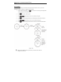
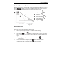
1
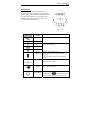
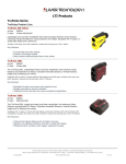
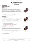
Laser Technology, Inc. TruPulse 200L ® © LTI 2013 PM TruPulse 200L 130 0001 User’s Manual LTI TruPulse 200L First Edition - Part Number 0144873 Copyright Notice: Information in this document is subject to change without notice and does not represent a commitment on the part of Laser Technology Inc. No part of this manual may be reproduced in any form or by any means, electronic or mechanical, including photocopying, recording, or information storage and retrieval systems, for any purpose other than the purchaser's personal use, without the express written consent of Laser Technology, Inc. Copyright © Laser Technology, Inc., 2013. All rights reserved. Patents: This product is covered by pending patent applications and/or the following issued U.S. Patents: 6,445,444; 5,612,779; 6,057,910; 6,226,077; 5,652,651; 7,920,080; 7,619,548. Trademarks: Criterion, Impulse, and TruPulse are trademarks of Laser Technology, Inc. LTI Contact Information: Laser Technology, Inc. 6912 South Quentin St. Centennial, CO 80112-3921 USA Phone: 1-303-649-1000 1-800-790-7364 (USA and Canada) Fax: Web Site: Email: 1-303-649-9710 www.lasertech.com [email protected] TruPulse 200L Reference Information: Record information about your TruPulse 200L in the table below. You can find this value: Serial Number Firmware Revision Number On the serial number sticker affixed to the TruPulse 200L or see page 12 for information. See page 12 for information. Value Laser Technology, Inc. TruPulse® 200L User's Manual Languages 1. English 2. Español 3. Français 4. Deutsch 5. 日本語 6. 汉语被简化 LTI TruPulse 200L User’s Manual - Table of Contents Page 1 TableofContentsǤ Precautions ....................................................................................................................... 2 Section 1 - Introducing the LTI TruPulse 200L ............................................................ 3 Basic Package ............................................................................................................ 4 Compatible Accessories............................................................................................. 4 Laser Range Sensor ........................................................................................................... 4 Targets ............................................................................................................................... 4 Tilt Sensor ......................................................................................................................... 5 Digital Processor ............................................................................................................... 5 Section 2 - Quick Start .................................................................................................... 6 Section 3 - Basic Operations ........................................................................................... 7 Battery ............................................................................................................................... 7 Installation ................................................................................................................. 7 Low Battery Warning ................................................................................................ 7 Buttons .............................................................................................................................. 8 Powering OFF the TruPulse 200L ............................................................................. 8 Display Indicators .............................................................................................................. 9 Display Indicator Test.............................................................................................. 11 Error Codes...................................................................................................................... 11 Firmware Revision Number ............................................................................................ 12 Neck Strap ....................................................................................................................... 13 Units of Measure ............................................................................................................. 14 Section 4 - Measurement Modes ................................................................................... 15 Distance Measurements ................................................................................................... 15 Notes about Measurements .............................................................................................. 16 Inclination Measurements................................................................................................ 16 Percent Slope ........................................................................................................... 16 Height Routine ................................................................................................................ 17 Vertical 2D Missing Line Routine ................................................................................... 18 Section 5 - Target Modes............................................................................................... 20 Section 6 - Care & Maintenance ................................................................................... 22 Section 7 - Specifications ............................................................................................... 23 Section 8 - Main Display LCD Characters .................................................................. 24 Laser Technology, Inc. TruPulse 200L User's Manual 1st Edition Page 2 Precautions Avoid staring directly at the laser beam for prolonged periods. The TruPulse® 200L is designed to meet FDA eye safety requirements and is classified as eye-safe to Class 1 limits, which means that virtually no hazard is associated with directly viewing the laser output under normal conditions. As with any laser device, however, reasonable precautions should be taken in its operation. It is recommended that you avoid staring into the transmit aperture while firing the laser. The use of optical instruments with this product may increase eye hazard. Never attempt to view the sun through the scope. Looking at sun through the scope may permanently damage your eyes. Never point the unit directly at the sun. Exposing the lens system to direct sunlight, even for a brief period, may permanently damage the internal components. Avoid direct sun exposure on the eyepiece. Exposing the eyepiece to direct sunlight can damage the internal display. Do not expose the instrument to extreme temperatures. TruPulse® 200L components are rated for a temperature range of -4 to +140° F (-20 to +60° C). Do not expose the instrument to temperatures outside this range whether in use or in storage. Section 1 - Introducing the LTI TruPulse 200L Page 3 Section 1 - Introducing the LTI TruPulse 200L Congratulations on the purchase of your TruPulse 200L, a cost-effective professional rangefinder. This compact and lightweight laser is a flexible tool for your measurement needs. Features of the TruPulse: • • • • • New graphic display makes it easy to use. Crystal clear optics and the heads up display lets you keep your eye on the target. The laser sensor and integrated tilt sensor measure slope distance, horizontal distance, vertical distance and inclination. The Target Mode allows you to select or eliminate targets; which helps you take the most accurate measurement possible in a variety of field conditions. Flexible, 2 or 3-point height routines and 2-dimensional Missing Line routine with auto sequencing. 1. 2. 3. 4. 5. 6 FIRE button (power ON) (UP) button (DOWN) button Eyepiece Tripod / Monopod mount Attachment Point (for neck strap and eyepiece cover) 7. Battery Compartment Cover 8. Transmit Lens 9. Receive Lens 10. Viewing Objective Figure #1 Operating Modes Measurement Modes Slope Distance Vertical Distance Horizontal Distance Inclination 3-Point Height Routine Missing Line Target Modes Standard Continuous** Closest** Farthest** Filter** System Setup Mode Units Selection **Advanced Targeting Modes. Laser Technology, Inc. TruPulse 200L User's Manual 1st Edition Page 4 Unpacking Your TruPulse 200L When you unpack your TruPulse 200L, check to make sure that you received everything that you ordered, and that it all arrived undamaged. Basic Package • • • • • TruPulse 200L Carrying Case Lens Cloth Neck Strap User's Manual Compatible Accessories • • Foliage Filter Tripod To learn more about any of the items listed above, please contact your LTI Sales Representative or an Authorized LTI Distributor. Understanding How the TruPulse 200L Works The TruPulse 200L consists of a laser range sensor, an integrated tilt sensor, and a digital processor. The TruPulse 200L has three buttons that access the unit's internal software, which controls the integrated sensors. Laser Range Sensor The laser range sensor emits invisible, eye safe, infrared energy pulses. The TruPulse 200L determines distance by measuring the time it takes for each pulse to travel from the indicator is displayed whenever the laser is rangefinder to the target, and back. The being transmitted. The laser may be active for a maximum of 5 seconds. Once the target is acquired or the laser has timed out, you can release the FIRE button. The TruPulse 200L has a broad spectrum of sensitivity and can work with both reflective and nonreflective targets. Targets When selecting a target, you should consider the following: • • • • Color: The brighter the color, the longer the range. Finish: Shiny finishes provide longer range than dull finishes. Angle: Shooting perpendicular to a target provides better range than shooting to a target at a sharp angle. Lighting Conditions: Overcast skies will increase the unit's maximum range, and sunny skies will decrease the unit's maximum range. Section 1 - Introducing the LTI TruPulse 200L Page 5 Tilt Sensor The integrated tilt sensor measures vertical angles that the TruPulse 200L uses to calculate height and elevation and to determine slope-reduced horizontal distances. The instrument held level is at 0°, and is rotated up through +90° and down through -90°. • • The laser is not active in the Inclination Measurement Mode. Generally, the inclination is measured when you press . However in (1) the Continuous Target Mode and (2) in the Height Measurement Mode, the inclination reading appears in the Main Display and the display updates as your aiming point changes as long as you press In these two situations, the measured inclination is based upon the aiming point when you release . Digital Processor The TruPulse 200L includes LTI's proprietary ASIC chip (Application-Specific Integrated Circuit). The ASIC chip combined with high-speed CPU processing allows the TruPulse 200L to deliver accurate and fast measurements. . Laser Technology, Inc. TruPulse 200L User's Manual 1st Edition Page 6 Section 2 - Quick Start 1. Install the batteries (page 7). 2. 3. Press to power ON the TruPulse 200L. Select a target such as a tree or a building. For this example, the target should be approximately 250 feet (82 yards or 75 meters) from you. Look through the eyepiece (see Figure #2) and use the crosshair to aim to the target. The in-scope LCD should look similar to Figure #3A. 4. Figure #2 o If the indicator is not displayed, press or until the displayed. 5. Press-and-hold . The indicator is displayed while the laser is active (Figure #3B). The laser will remain active for a maximum of 5 seconds while acquiring data about the target. o 6. indicator is If the target is not acquired, release and repeat this step. Release once the distance is displayed (Figure #3C). The measurement will be displayed steady until you press a button or the unit powers OFF. o o o or to scroll through the Press measurement modes and see the results acquired for each function. Repeat steps #3-#6 above to take another measurement. Simultaneously press-and-hold and for 4 seconds to power OFF the TruPulse 200L. Figure #3 Section 3 - Basic Operations Page 7 Section 3 - Basic Operations Battery Installation The TruPulse 200L is powered by a 3 Volt Lithium battery commonly referred to as CR123A or also referred to as CR123. 1. 2. 3. Remove the battery compartment cover by gently pressing the clip to release the cover. Install the battery as shown in Figure #4A. The battery must be oriented (+/-) as shown in the figure and also on the indication sticker found inside the battery compartment. Replace the battery compartment cover by aligning the tab located on the top the cover with the grooved edge of the battery compartment, and press the cover until the tab locks into position. 1. 2. 3. Battery Compartment Cover Tab Clip Figure #4 Low Battery Warning The TruPulse 200L monitors the incoming battery voltage. Figure #5 shows the location of the battery status indicator. • • When the voltage drops below 2.6V, the BATT status indicator flashes every 5 seconds, alternating with the normally displayed information. o You should replace the batteries as soon as possible. When the voltage drops below 2.4V, the BATT status indicator stops flashing and is displayed steady. At this point, system operation is locked. o You must replace the batteries to return to normal system operation. Figure #5 Laser Technology, Inc. TruPulse 200L User's Manual 1st Edition Page 8 Buttons The TruPulse 200L has three buttons. With the TruPulse 200L in your right hand and looking through the eyepiece, is located on top, near your index finger. are located on the left side of the instrument. and Measurement Modes Powers ON the unit. Distance Measurement: fires the laser. Inclination: Release “locks” tilt sensor in (1) Height Measurement Mode and (2) Continuous Target Mode. Height Routine (HD) Fires the laser. (INC) Release “locks” tilt sensor. Target Modes System Setup Mode Selects option and returns to the Measurement Mode. Measurement Modes Press to scroll to the previous Measurement Mode. (UP) Press-and-hold 4 seconds to access the Target Mode. Height Routine Target Modes System Setup Mode Clears the last measurement and re-displays the previous prompt. Press to scroll to the previous option. Measurement Modes Press to scroll to the next Measurement Mode. (DOWN) Press-and-hold 4 seconds to access the System Setup Mode. Height Routine Target Modes System Setup Mode Exits the Height Routine. Press to scroll to the next option. Powering OFF the TruPulse 200L To power OFF the unit, simultaneously press-and-hold and for 4 seconds. To conserve battery power, the TruPulse 200L powers itself OFF if no button presses are detected after 2 minutes. Section 3 - Basic Operations Page 9 Display Indicators Figure #6 shows the LCD in-scope display. The TruPulse 200L’s internal software is organized into options. Each option represents a specific measurement or setup function and has a corresponding display indicator. Refer to the figure and table below for information about each indicator. Figure #6 Main Display Percent Slope Displays messages and measurement results. Inclination measurement units. Degrees Feet Distance measurement units. Selection available in the System Setup Mode. Meters Yards Battery Status Crosshair Laser Status Continuous Target Mode Flashing: battery voltage is low. Steady: battery voltage is too low for system operation. Not Visible: battery voltage is within acceptable range. Serves as the aiming point reference, both horizontally and vertically. Visible: laser is firing. Not Visible: laser is not active. The unit continuously acquires targets and displays is held down. The distance measurements while to the most recently acquired target is displayed. Laser Technology, Inc. TruPulse 200L User's Manual 1st Edition Page 10 Inclination Measurement Mode Slope Distance Measurement Mode Horizontal Distance Measurement Mode Vertical Distance Measurement Mode Azimuth Straight line distance between the TruPulse 200L and the target. The level distance between the TruPulse 200L and the plane of the target. The distance between the target and the perpendicular to the path of the horizontal distance. Not available. Missing Line Measurement Routine Two-step Missing Line Routine finds the connecting vector (or missing line) between two points. Height Measurement Routine Three-step height routine. The final calculation represents the vertical distance between the points on the target represented by ANG1 and ANG2. Closest Target Mode Farthest Target Mode No Indicator The angle of inclination between the TruPulse 200L at level and the target. Filter Mode is held The unit logs multiple targets while down. The circle denotes that additional targets have been acquired. Of the targets acquired, the distance to the closest target displays. is held The unit logs multiple targets while down. The circle denotes that additional targets have been acquired. Of the targets acquired, the distance to the farthest target displays. ‘F’ appears as the left-most character of the Main Display to indicate Filter Mode is active. Similar to Standard, single shot mode, but the laser’s sensitivity is reduced so it only detects pulses returned from a reflector. The optional foliage filter must be used in conjunction with this mode. Section 3 - Basic Operations Page 11 Display Indicator Test To verify that all display indicators are working properly: 1. 2. Start with the TruPulse 200L powered OFF, press-and-hold . Compare the in-scope display to the Figure #6 (page 9) to verify that all indicators are working properly. 3. Release to start normal operation. Error Codes Error conditions can occur in a measurement or in the system hardware. To make sure that you never get an erroneous measurement, the TruPulse 200L monitors both system hardware and measurements. When the instrument detects an error condition, it displays and error code instead of a measurement. Error codes appear in the main display and are in the form of “Exx”, where “xx” is an error code number. Figure #7 shows an example error code, E36. If an error code persists: 1. 2. 3. Release and press again to try to retake the measurement. Remove and re-install the batteries and then try to retake the measurement. If the above steps do not resolve the error, contact LTI or an Authorized LTI Distributor for assistance. Refer to the inside front cover for LTI contact information. Figure #7 Laser Technology, Inc. TruPulse 200L User's Manual 1st Edition Page 12 Firmware Revision Number The firmware revision numbers provide manufacturing information about your TruPulse 200L. To display the main and auxiliary firmware revision numbers: 1. Start with the TruPulse 200L powered OFF, press-and-hold . 2. Do not release until done. If you release the button too early, power OFF the TruPulse 200L and repeat step #1. Looking through the eyepiece: to display the main firmware revision number. The display should o Press look similar to the example below (1.02 in Figure #8). o o Press to display the instrument serial number. The display should look similar to the example below (123 in Figure #8). Figure #8 Section 3 - Basic Operations Page 13 Neck Strap To attach the neck strap: 1. 2. 3. 4. 5. Disconnect the anchor end of the strap using the buckle. Feed loop around metal bar. Thread the Neckstrap through the loop. Gently tighten to secure. Reconnect anchor end of the strap using the buckle. Figure #9 Laser Technology, Inc. TruPulse 200L User's Manual 1st Edition Page 14 Units of Measure The TruPulse 200L allows you to choose the units of measure. Distance: meters, yards or feet. Inclination: degrees or % Slope. To toggle the units selection: 1. for 4 seconds to access the System Setup Mode. From the Measurement Mode, press “UnitS” will appear in the Main Display. 2. Press to select the “UnitS” option. 3. Press or 4. Press to select the displayed distance unit and display the inclination unit option. 5. Press or 6. Press to select the displayed inclination unit and return to the Measurement Mode. to display the previous or next distance unit option. to display the previous or next inclination unit option. Figure #10 Each time the TruPulse 200L is powered ON, it will return to the same unit setting that was last used. Section 6 - Target Modes Page 15 Section 4 - Measurement Modes When you power ON the TruPulse 200L, the last used Measurement Mode will be active. Press or to display the previous or next Measurement Mode. Figure #11 shows the five different types of measurements that the TruPulse 200L can take. Slope Distance Inclination Horizontal Distance Vertical Distance Height Routine Figure #11 Distance Measurements The basic steps for taking any distance measurement: 1. Look through the eyepiece and use the crosshair to aim to the target. 2. Press-and-hold . The indicator is displayed while the laser is active. The laser will remain active for a maximum of 5 seconds while acquiring data about the target. o 3. If the target is not acquired in the 5 second period, release repeat this step. and Once the measurement is displayed, release . The measurement will be displayed steady until you press any button or the unit powers OFF. Laser Technology, Inc. TruPulse 200L User's Manual 1st Edition Page 16 Notes about Measurements or to scroll through the individual measurement functions Press and see the results acquired for each function. • Both inclination and distance are measured in the • , Slope Distance Horizontal Distance modes. Vertical Distance Example Range Measurement: , and = 12.5 meters = 1.6 meters = 12.6 meters = 7.3 degrees • When you scroll to the Height Function , the Main Display will be blank and the will be flashing. • In the Inclination Mode , the Main Display will be blank for all other measurement functions since the laser is not active when measuring inclination only. The last measurement does not need to be cleared before acquiring your next target. Each time the TruPulse 200L is powered ON, it will return to the same measurement mode that was last used. • • Inclination Measurements The laser is not active in the Inclination inclination is measured when you press Measurement Mode. Generally, the . However, in (1) the Continuous Target Mode and (2) in the Height Measurement Mode , the inclination reading appears in the Main Display and the display updates as your aiming point changes as long as you press . Percent Slope Percent slope, indicated by , is a calculation equal to 100 times the tangent of the inclination angle. It is a variant way of expressing the inclination. You can get percent slopes only in the basic measurement displays, never in the Height measurement displays. Note also that the instrument never downloads a percent slope. It always downloads the inclination angle. An inclination angle of 5 degrees for example is equal to a slope of about 8.75 percent. Section 6 - Target Modes Page 17 Height Routine Height Measurements involve a simple routine that prompts you to take 3 shots to the target: Horizontal Distance, Inclination Angle base and Inclination Angle top. The TruPulse 200L uses these results to calculate the height of the target. Figure #12 shows the three shots required for the height routine. 1. A = Horizontal Distance B = Top Angle C = Base Angle D = Height Figure #12 Select your target and look through the eyepiece, using the indicator displays crosshair to aim to your target. The steady and the indicator flashes; prompting you to measure the Horizontal Distance to the “face” of the target. 2. Press-and-hold . The indicator is displayed while the laser is active. The laser will remain active for a maximum of 5 seconds while acquiring data about the target. The measured horizontal distance appears briefly in the Main Display and then Ang_1 appears, and the indicator flashes; prompting you to measure the inclination to base (or top) of the target. 3. Press-and-hold and aim to the base (or top) of the target. The measured inclination appears in the Main Display and is updated as long as us you continue to hold . The measured inclination is “locked” when you release . The measured inclination appears briefly in the Main Display and then Ang_2 appears and the indicator flashes; prompting you to measure the inclination to the top (or base) of the target. Figure #13 Laser Technology, Inc. TruPulse 200L User's Manual 1st Edition Page 18 4. Press-and-hold and aim to the top (or base) of the target. The measured inclination appears in the Main Display and is updated as long as you continue to . The measured inclination is “locked” when you release . The hold measured inclination appears briefly in the Main Display and then the calculated Height is displayed steady until you press any button or the unit powers OFF. During the height routine: • • • Press to re-shoot the previous point. Press to exit the height routine. The laser is not active while measuring the ANG1 and ANG2 values. As long as you hold , the inclination reading is displayed and updated as your aiming point changes. The measured inclination is based upon your aiming point when you release • When the height result is displayed, just press routine and repeat the steps. . to start the Vertical 2D Missing Line Routine The Vertical 2D Missing Line Routine: Displays Horizontal Distance Vertical Distance two remote points. , Slope Distance and Inclination , between The Vertical 2D Missing Line Routine calculates distances and angles to describe the relationship between two points in two-dimensional space (connecting vector). This routine is ideal for remote slope determinations and changes in elevation from one location. The simple routine prompts you to take two shots to targets: "Shot 1” and “Shot 2”. The TruPulse uses the results to calculate four variables between the two points: slope distance, inclination, horizontal distance, and vertical distance as shown in figure to the right. • : Horizontal Distance: Horizontal component of the missing line. • : Vertical Distance: Change in elevation between point #1 and point #2. • • : Slope Distance: Length of the missing line. : Inclination between point #1 and point #2. Section 6 - Target Modes Page 19 During the Vertical Missing Line Routine: • • Press Press 1. Select your first target and look through the eyepiece, using the crosshair to aim to your target. The indicator displays steady and the indicator flashes; prompting you to measure the Horizontal Distance to the first target. Press-and-hold . The indicator is displayed while the laser is active. The laser remains active for a maximum of 5 seconds while acquiring data about the target. The measured horizontal distance appears in the Main Display. Once the button is released, "SHot2" appears indicator flashes (with steady and the steady); prompting you to measure the Horizontal Distance to the second target. Looking through the eyepiece and using the crosshair to aim to the second target. 2. 3. 4. 5. to re-shoot Shot 1. to exit the Missing Line Routine. . The indicator is displayed Press-and-hold while the laser is active. The laser remains active for a maximum of 5 seconds while acquiring data about the target. The measured horizontal distance to the second target appears in the Main Display. Once you release , and are steady and the calculated horizontal distance of the missing line is displayed. The measurement displays steady until you press any button or the unit powers off. Figure #14 At this time, you can: • • • Press or to scroll and see the other missing line measurements results ( , and ). or until Shot 2 and ML Reshoot Shot 2 by pressing appear steady in the display as well as HD flashing, prompting you to measure the horizontal distance to the second target (or new target). Go to #4 above. to exit the missing line results and return to Shot 1. Press Laser Technology, Inc. TruPulse 200L User's Manual 1st Edition Page 20 Section 5 - Target Modes The TruPulse 200L has five Target Modes which allow you to select or eliminate targets and to take the most accurate measurements possible in various field conditions. 1. 2. 3. From the Measurement Mode, press for 4 seconds. The active Target Mode appears in the Main Display. Press or to display the previous or next Target Mode. Press to select the displayed Target Mode and return to the Measurement Mode. o Std = Standard: Single shot mode. o Con = Continuous: Press-and-hold . Once the target is acquired, the TruPulse 200L can continuously acquire additional targets for a maximum of 5 seconds. The most recently acquired target appears in the Main Display. o CLO = Closest: Press-and-hold . Once the initial target is acquired, the TruPulse 200L can acquire indicator denotes that additional targets. The additional targets have been acquired. The closest acquired target always appears in the Main Display. o o FAr = Farthest: Press-and-hold . Once the initial target is acquired, the TruPulse 200L can acquire indicator denotes that additional targets. The additional targets have been acquired. The farthest acquired target always appears in the Main Display. Flt = Filter: In this mode the laser’s sensitivity is reduced to only detect pulses returned from a reflector. The optional foliage filter must be used in conjunction with this mode. In this mode, measurements always include ‘F’ as the left most character in the Main Display. Typical maximum distance is 350 feet to a 3-inch reflector. Figure #15 Section 6 - Target Modes Page 21 • • • The selected Target Mode remains active until you repeat the above steps and select a different Target Mode. Each time the TruPulse 200L is powered ON, it will return to the same Target Mode that was last used. In Closest and Farthest Modes, the minimum separation distance between targets is approximately 20 meters. Laser Technology, Inc. TruPulse 200L User's Manual 1st Edition Page 22 Section 6 - Care & Maintenance The battery is the only user-replaceable parts in the TruPulse 200L. Do not remove any screws. To do so will effect or void the LTI Limited Warranty. Temperature Range The instrument is rated for an operating temperature range of -4 to +140º F (-20 to +60º C). Do not expose the TruPulse 200L to temperatures outside this range. Protecting from Moisture and Dust The TruPulse 200L is sealed to provide protection from normally expected field conditions. It is protected from dust and rain, but will not withstand submersion. If water leakage is suspected: 1. 2. 3. Power OFF the TruPulse 200L. Remove the battery. Air dry the TruPulse 200L at room temperature with the battery compartment open. Protecting from Shock The TruPulse 200L is a precision instrument and should be handled with care. It will withstand a reasonable drop shock. If the unit suffers from a severe drop shock, you may need to send the unit to LTI for service repair. Transporting When transporting the TruPulse 200L, the unit should be secured in the provided carrying case. The provided neck strap can be used when carrying the TruPulse 200L in the field. Cleaning Clean the TruPulse 200L after each use, before returning it to its carrying case. Check all of the following items: Excess moisture. Towel off excess moisture, and air dry the instrument at room temperature with the battery removed and the battery compartment open. Exterior dirt. Wipe exterior surfaces clean to prevent grit buildup in the carrying case. Isopropanol may be used to remove dirt and fingerprints from the exterior. Transmit and Receive Lenses. Use the provided lens cloth to wipe the lenses. Failure to keep the lenses clean may damage them. Storing If you won't be using the TruPulse 200L again soon, remove the battery before storing the instrument. Section 9 – Specifications Page 23 Section 7 - Specifications All specifications are subject to change without notice. Please refer to LTI's website for current specifications. If you are not able to locate the information on the website or if you do not have internet access, please contact LTI via phone or fax. Weight: 10 ounces (285 g) Size: 4.5" x 4" x 2" (11.5 cm x 10 cm x 5 cm) Range Limits: 3 to 5,740 ft (1 m to 1,750 m) to reflective target 3 to 3,280 ft (1 m to 1,000 m) typical to non-reflective Range Accuracy: ±3 ft (±1 m) to any target at any range Range Resolution: 1 ft, yd, m Range Units: Feet, Yards and Meters Inclination Limits: ±90 degrees Inclination Accuracy: ± 0.5 degrees Inclination Resolution: 0.5 degree, 1% Inclination Units: Degrees, % Slope Power: 3.0 volts DC nominal; (1) CR123A battery (Alkaline, NiCd/NiMH, Lithium) Battery Duration: 8 Hours Continuous Use Eye Safety: FDA Class 1 (CFR 21) Environmental: Water and dust resistant; IP 54 Temperature: -4 to +140° F (-20 to +60° C) Optics: 4X Magnification Display: In-scope LCD Laser Technology, Inc. TruPulse 200L User's Manual 1st Edition Page 24 Section 8 - Main Display LCD Characters The LCD Main Display is used to convey messages and measurement results. When all of the indicators are active the Main Display looks like: Numbers 0-9: Alpha Characters: =a =g =r =d =i =s =e =l =t =f = n =u Due to the limited number of characters available, many messages have to be abbreviated. The table below lists the messages that appear in the Main Display. Message Explanation Page # Angle 1. Height Routine. 17 Angle 2. Height Routine. 17 Farthest target mode. 20 Filter target mode. 20 Standard target mode. 20 Units. 14