1
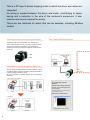
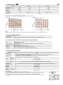
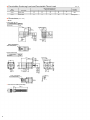
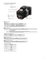
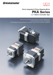
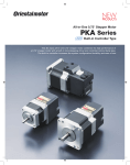
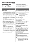
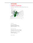
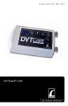
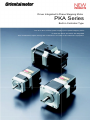
Driver Integrated 5-Phase Stepping Motor
PKA Series
Built-in Controller Type
This is an all-in-one DC power supply input 5-phase stepping motor
in which the driver and motor are integrated.
This contributes to space saving and a reduction in the size of the customer's equipment.
This is a DC input 5-phase stepping motor in which the driver and motor are
integrated.
No wiring is needed between the driver and motor, contributing to space
saving and a reduction in the size of the customer's equipment. It also
reduces man hours required for wiring.
There are two methods of control that can be selected, including Modbus
control.
Contributes to Space Saving and Reduced Wiring in the Equipment
Two Control Method Options
The driver and the motor are integrated. Also, since there is a
built-in positioning function, there is no need for a pulse generator.
The system is simplified, contributing to space saving and a
reduction in the size of the customer's equipment. It also requires
less wiring.
Motor
Data Setting Software✽
MEXE02
Driver
1
Control Module
OPX-2A (Sold separately)
or
Contributes to a Shorter Equipment Startup Time
Computer
(Not supplied.)
Since no wiring is needed between the motor and driver or driver
and pulse generator, wiring time is reduced. This also decreases the
number of problems caused by wiring.
All of this contributes to a shorter startup time for the customer's
equipment.
RS-485
communication
Motor
● Motor + Driver + Pulse Generator
Driver
Pulse Generator
Programmable
Controller
✽ 1 Data Setting Software
MEXE02
Operating data settings, parameter
changes, and monitoring are done
on a computer.
Motor
Equipment
Control Box
Compatible software can be downloaded from
the Oriental Motor website.
http://www.orientalmotor.eu
● PKA Series
Programmable
Controller
● Operating Status Waveform Monitoring
Motor
Equipment
2
Control Box
Reduces the Load on High-Order Programmable Controllers
I/O Control
The function of a pulse generator is
built in, letting you build an operation
system by connecting directly to a
programmable controller. Since no pulse
generator is required, space is saved
and the system is simplified.
Programmable Controller
or
● Positioning Operation
The motor's operating speed and traveling amount are set in the
operating data, and operations are performed in accordance with
the selected operating data.
Modbus Control
Computer
A positioning function is built in, ensuring that the traveling amount,
speed, and other operating data is retained in the motor. It is also
equipped with a variety of other operation functions in addition to
the positioning operation, such as continuous operation and a
return-to-home operation. This contributes to a reduced load on the
programmable controller, and a simplified program.
◇ Linked Operation
Operating data, parameter settings or
operation commands can be input via
RS-485 communication. A maximum
of 31 motors can be connected to one
programmable controller. Multi-axis
simultaneous starting is also possible.
The protocol is compatible with Modbus
(RTU) and can be easily connected via a
programmable controller, etc.
If the operating data is set to "linked", continuous positioning with
the following data number is possible with one START signal.
[Linked operation]
Data
Data
No. 01 No. 02
If data No. 01 is selected and START input,
linked driving from data No. 01 to No. 03 is
performed without the motor stopping.
Data
No. 03
[Linked operation 2]
CW rotation
If data No. 01 is selected and START input, the
data No. 01 operation is executed. After that, it
is stopped for only the set dwell time✽ and
then the operations from data No. 02 to No. 03
are executed. Operating data with a different
rotation direction can also be linked.
Dwell time
Data
No. 01
Programmable Controller
Data
No. 02
Data
No. 03
✽ Dwell time is the wait time until the next
positioning operation starts.
CCW rotation
◇ Sequential Operation
If the operating data is set to "sequential positioning", positioning of the next
data number is performed in sequence every time a START signal is input.
● Speed Control Operation
The motor operates continuously while a FWD signal or RVS signal is
input. Because it operates at the speed of the operating data set
beforehand, multistep speed-change operation is possible by changing
the data number.
+ Direction
Motor operation
− Direction
FWD Input
RVS Input
M0∼ M5 Input
ON
OFF
ON
OFF
ON OFF 01
02
01
03
● Return-To-Home Operation
It is equipped with a return-to-home operation, so return-to-home can
be done easily by wiring a sensor.
3
■ System Configuration
Accessories (Sold separately)
2
①Control Module Cable✽
2
②Control Module✽
(➜ Page 10)
Data Setting Software
3
MEXE02✽
③Data Setting Software 2
Communication Cable✽
(➜ Page 10)
(➜ Page 10)
or
To USB port
Computer✽
1
PKA Series
24 VDC
1
Power Supply✽
Programmable
1
Controller✽
Sensor✽
1
Accessories (Sold separately)
⑤Flexible✽
Coupling
④Motor Mounting
4
Bracket✽
Name
① Control Module Cable
② Control Module
Data Setting Software
Communication Cable
This communication cable is used for connecting a computer and motor.
④ Motor Mounting Bracket
⑤ Flexible Coupling
⑥
⑥RS-485 Communication
Cable
(➜ Page 11)
Overview
This is a cable that connects a control module or data setting software communication cable to the PKA series. (0.1 m)
Various data can be edited, monitored and operated. Communication cable (5 m) included.
Number
③
4
RS-485 Communication
Cable
Page
10
10
10
This is a dedicated mounting bracket for the motor.
This is a coupling that connects the motor shaft to the driven shaft.
✽4
✽4
This cable is used for daisy-chain connection of PKA series equipment.
There are also cables for connecting PKA series equipment and a network converter, or PKA series equipment and other
RS-485 compatible products.
11
● A User's Manual that explains how to operate this product is available. For details, please contact the nearest Oriental Motor sales office or download the manual from the Oriental Motor website.
http://www.orientalmotor.eu
● System Configuration Example
PKA Series
PKA566KD
Sold Separately
Motor
Flexible
Installation Bracket
Coupling
PAL2P-5
MCV190808
✽ 1 Not supplied.
✽ 2 This is required for driving I/O control.
✽ 3 Compatible software can be downloaded from the Oriental Motor website.
A CD-ROM is also distributed.
✽ 4 For details, please contact the nearest Oriental Motor sales office.
● The system configuration shown above is an example. Other combinations are also available.
■ Product Line
Product Name
PKA544KD
PKA566KD
4
■ Specifications
Product Name
Max. Holding Torque
Holding Torque at Motor Standstill
Rotor Inertia
Rated Current
Basic Step Angle
Power Supply Input
Excitation Mode
PKA544KD
0.18
0.09
-7
54×10
0.75
N·m
N·m
2
J:kg·m
A/Phase
0.72˚
24 VDC±10%
1.4 A
24 VDC±10%
2.5 A
Microstep
■ Speed - Torque Characteristics
PKA544KD
0.20
PKA566KD
0.83
0.41
-7
280×10
1.4
fs: Max. starting frequency
PKA566KD
Current: 0.75 A/phase Step angle: 0.72˚/step
2
External load inertia: JL = 0 kg·m
1.2
Current: 1.4 A/phase Step angle: 0.72˚/step
2
External load inertia: JL = 0 kg·m
1.0
0.15
0.8
Pullout Torque
2
0.10
1
0.05
0
0
0
Pullout Torque
0.6
Driver Input Current
fs
500
0
(0)
5
(50)
1000
1500
Speed [r/min]
2000
10
15
(100)
(150)
Pulse Speed [kHz]
2500
Resolution 1
(Resolution 10)
4
0.4
2
0.2
0
0
0
0
(0)
Driver Input Current
fs
200
400
2.5
(25)
600
800
Speed [r/min]
5
(50)
Pulse Speed [kHz]
1000
7.5
(75)
1200
Resolution 1
(Resolution 10)
Note
● Depending on the driving conditions, a considerable amount of heat may be generated by the motor. Be sure to keep the motor case temperature at 75˚C max.
■ Control Circuit Specifications
No. of Positioning Data Sets
Operation functions
64
Positioning Operation, Return-To-Home Operation, Continuous Operation, JOG Operation, Test Operation
■ Control Circuit RS-485 Communication Specification
Protocol
Modbus protocol (Modbus RTU mode)
EIA-485 compliance
Twisted-pair wire (TIA/EIA-568B CAT5e or greater recommended) is used up to a total extension length of 50 m.
Transmission/Reception Mode Half-duplex communication
Baud Rate
9600 bps/19200 bps/38400 bps/57600 bps/115200 bps
Physical Layer
Asynchronous mode (data: 8-bit, stop bit: 1-bit/2-bit, parity: none/odd/even)
Connection Type
Up to 31 units can be connected to one programmable controller (master equipment).
Electrical Characteristics
■ General Specifications
Specifications
Heat-Resistant Class
Insulation Resistance
Dielectric Strength
Ambient Temperature
Ambient Humidity
Atmosphere
Degree of Protection
Temperature Rise
1
Stop Position Accuracy✽
Shaft Runout
2
Radial Play✽
3
✽
Axial Play
Concentricity of Installing Pilot to
the Shaft
Perpendicularity of Installation
Surface to the Shaft
Operating
environment
(In operation)
Motor
130 (B)
The measured value is 100 MΩ min. when a 500 VDC megger is applied as follows under normal ambient temperature and humidity: · FG
terminal and motor case — Between power input terminals
No abnormality is judged with the following application for 1 minute under normal ambient temperature and humidity: · FG
terminal and motor case — Between power input terminals 500 VAC 50 Hz or 60 Hz
0∼ +50˚C (non-freezing)
85% max. (non-condensing)
Use in an area without corrosive gases and dust. The product should not be exposed to water, oil or other liquids.
IP20
Winding temperature rise is 80˚C max. (measured by the resistance change method) at the rated current, at standstill, and 5-phases energized.
±3 arc minutes (±0.05˚)
4
0.05 T. I. R. (mm)✽
0.025 mm max. of 5 N
0.075 mm max. of 10 N
0.075 T. I. R. (mm)✽
4
0.075 T. I. R. (mm)✽
4
✽ 1 This value is for full step under no load. (The value changes with the size of the load.)
✽ 2 Radial Play: Displacement in shaft position in the radial direction when a 5 N load is applied in the vertical direction to the tip of the motor shaft.
ϕ0.075
A
0.05
✽ 3 Axial Play: Displacement in shaft position in the axial direction when a 10 N load is applied to the motor shaft in the axial direction.
✽ 4 T. I. R. (Total Indicator Reading): The total dial gauge reading when the measurement section is rotated one revolution centered on the reference
axis center.
A
0.075
A
5
■ Permissible Overhung Load and Permissible Thrust Load
Motor
Frame Size
42 mm
60 mm
Max. Permissible Overhung Load
Distance from Shaft End mm
Product Name
0
20
63
PKA544KD
PKA566KD
5
25
75
10
34
95
■ Dimensions (Unit = mm)
● Motor
Frame Size 42 mm
Product Name
PKA544KD
Mass kg
0.37
88.5
20±1
39
4×M3×4.5 Deep
42
31±0.2
2
15±0.25
11.7
62.8
15.4
30.5
55959− 1 230 (MOLEX)
43045− 0400 (MOLEX)
Frame Size 60 mm
Product Name
PKA566KD
Mass kg
0.89
107
24±1
57.5
42
1.5
20±0.25
4×ϕ4.5 Thru
60
50±0.35
A
A
15.4
11.7
55959− 1230 (MOLEX)
43045− 0400 (MOLEX)
32
30
7.5±0.15
A− A
● Connection Cable (Included)
9.3
1 2
11 12
6
600±20
Unit = N
15
52
130
20
−
190
Permissible
Thrust Load
Motor
Self-Weight max.
■ Connection and Operation
● Names and Function of Parts
Power Source & I/O Signal
Connector (CN1)
RS-485 Communication Connector (CN2,3)
Control Module Connector (CN4)
Baud Rate Setting Switch (SW3)
Model Setting Switch (SW2)
Function Switch (SW1)
Signal Monitor Display
Signal Monitor Display
◇ LED Indicator
Indication
PWR
ALM
DAT
ERR
Color
Green
Red
Green
Red
Function
Lighting Condition
Power Supply Indication
When the power supply is input
Alarm Indication
When protective function is activated (blinking)
Communication Indicator
When data is being received and sent
Communication Error Indicator When communication data is abnormal
Function Switch (SW1)
Indication
No.
1,2
SW1
3
4
Function
This sets the terminating resistance for RS-485 communication (120 Ω ) (factory setting: OFF).
OFF: No terminating resistance
ON: Terminating resistance
This sets the model number in combination with the model setting switch (SW2) (factory setting: OFF).
This sets the protocol for RS-485 communication (factory setting: OFF).
◇ RS-485 Communication Protocol Setting
Destination
No.
4
Network
Converter Connection
OFF
Modbus RTU Mode
ON
Model Setting Switch (SW2)
Indication
SW2
Function
This is set during use with RS-485 communication. It sets the model number (factory setting: 0).
Baud Rate Setting Switch (SW3)
Indication
SW3
Function
This is set during use with RS-485 communication. It sets the baud rate (factory setting: 7).
◇ RS-485 Baud Rate Setting
No.
0
1
2
3
4
5~6
Baud Rate (bps)
9600
19200
38400
57600
115200
Not used
7
625000
(Network Converter Connection)
8~F
Not used
7
Power Source & I/O Signal Connector (CN1)
Indication
CN1
Pin No.
1
2
3
4
5
6
7
8
9
10
11
12
Signal Name
FG
GND
IN-COM
+24 VDC
IN0
IN1
IN2
IN3
OUT0+
OUT0−
OUT1+
OUT1−
Content
Frame Ground
Power Supply GND
Input Common
+24 VDC Power Supply Input
Control Input 0 (initial value: +LS)✽
Control Input 1 (initial value: − LS)✽
Control Input 2 (initial value: HOMES)✽
Control Input 3 (initial value: STOP)✽
Control Output 0 (initial value: ALM)✽
Control Output 1 (initial value: READY)✽
✽ Assigned functions are set by means of the parameter settings. The above is the initial value. For details, refer to the User's Manual.
The following input signals can be assigned to input terminals IN0∼ 3.
0: Not used
1: FWD
2: RVS
3: HOME
4: START
5: SSTART
6: +JOG
7: − JOG
8: MS0
9: MS1
10: MS2
11: MS3
12: MS4
13: MS5
16: FREE
17: AWO
18: STOP
24: ALM-RST
25: P-PRESET
27: HMI
32: R0
33: R1
34: R2
35: R3
Input Signal
36: R4
37: R5
38: R6
39: R7
40: R8
41: R9
42: R10
43: R11
44: R12
45: R13
46: R14
47: R15
48: M0
49: M1
50: M2
51: M3
52: M4
53: M5
60: +LS
51: M3_R
52: M4_R
53: M5_R
67: READY
68: MOVE
70: HOME-P
72: TIM
73: AREA1
74: AREA2
75: AREA3
80: S-BSY
61: − LS
62: HOMES
63: SLIT
The following output signals can be assigned to output terminal OUT0∼ 1.
0: Not used
1: FWD_R
2: RVS_R
3: HOME_R
4: START_R
5: SSTART_R
6: +JOG_R
7: − JOG_R
8: MS0_R
8
9: MS1_R
10: MS2_R
11: MS3_R
12: MS4_R
13: MS5_R
16: FREE_R
17: AWO_R
18: STOP_R
32: R0
33: R1
34: R2
35: R3
36: R4
37: R5
38: R6
39: R7
40: R8
41: R9
Output Signal
42: R10
43: R11
44: R12
45: R13
46: R14
47: R15
48: M0_R
49: M1_R
50: M2_R
60: +LS_R
61: − LS_R
62: HOMES_R
63: SLIT_R
65: ALM
66: WNG
● Connection Diagram
◇ Connection to Programmable Controller
● Example of Connection with Current Sink Output Circuit (PNP specification)
Controller
Control Circuit
+24 VDC
IN0
6.6 kΩ
IN1
6.6 kΩ
IN2
6.6 kΩ
IN3
6.6 kΩ
1 kΩ
1 kΩ
1 kΩ
1 kΩ
IN-COM
0V
10 mA max.
+24 VDC max.
OUT0+
R
OUT0−
OUT1+
R
OUT1−
0V
● Example of Connection with Current Sink Output Circuit (NPN specification)
Controller
Control Circuit
IN0
6.6 kΩ
IN1
6.6 kΩ
IN2
6.6 kΩ
IN3
6.6 kΩ
1 kΩ
1 kΩ
1 kΩ
1 kΩ
+24 VDC
IN-COM
0V
+24 VDC max.
10 mA max.
R
OUT0+
OUT0−
R
OUT1+
OUT1−
0V
Note
● Please use 24 VDC for the input signal.
● Please use 24 VDC 10 mA max. for the input signal. When the current value exceeds 10 mA, connect the external resistor R to keep the current 10 mA max. ● If
noise generated by the power supply cable causes a problem with the specific wiring or layout, shield the cable or use ferrite cores.
9
Accessories (Sold separately)
These accessories are needed to change parameter settings, data settings, etc. in the PKA Series.
Data Setting Software
MEXE02
Control Module
OPX-2A
USB Cable 0.5 m
or
Control Module Cable
CC001IF-CA
Computer
CN4
(Not supplied.)
Communication Cable for Data
Setting Software
CC05IF-USB
Connected to control module cable
Control Module Cable
This is a cable that connects an OPX-2A or data setting software
communication cable to the PKA Series.
■ Product Line
PC Interface Cable 5 m
Note
● A dedicated driver must be installed to connect to a computer.
■ Dimensions
Product Name
CC001IF-CA
6.8
5.5
ϕ2.8
28.6
100±10
36
2
Control Module
Changes can be made to parameter settings, data settings, etc. It can also
be used for speed and I/O monitoring, teaching, etc.
■ Product Line
<Enlarged view>
Product Name
OPX-2A
■ Dimensions (Unit = mm)
● Control Module
■ Specifications
Indication
Cable Length
Operating Ambient Temperature
● Installation Hole
Dimensions
Mass: 0.25 kg
LED
5m
0∼ +40˚C (non-freezing)
91.8
(Installation Plate Thickness 1∼ 3 mm)
21.5
96
6.1
92 0 0+.8
Panel Cut-Out Dimensions
Cable ϕ4.7 5000 mm
Communication Cable for Data
Setting Software
This communication cable is used for connecting a computer and motor.
■ Product Line
Product Name
CC05IF-USB
10
38
■ Data Setting Software MEXE02
Data setting software can be downloaded from the Oriental Motor website.
http://www.orientalmotor.eu
A CD-ROM is also distributed.
For details, please go to the Oriental Motor website or contact the nearest Oriental Motor sales office.
■ Operating Environment
● Operating System (OS)
● PC
● Microsoft Windows 2000 Professional Service Pack 4
Be sure to use the Rollup1 provided by Microsoft Corporation.
Check "Program Additions and Deletions" to see if Rollup1 is
used.
Recommended CPU✽
Video Adapter and Monitor with Resolution of XGA
(1024 × 768) min.
Display
Recommended Memory✽
The following OS are only compatible with 32-bit (x86) and 64-bit
(x64) versions.
● Microsoft Windows XP Home Edition Service Pack 3
● Microsoft Windows XP Professional Service Pack 2
1
● Microsoft Windows XP Professional Service Pack 3✽ ●
Microsoft Windows Vista Home Basic Service Pack 2 ●
Microsoft Windows Vista Home Premium Service Pack 2 ●
Microsoft Windows Vista Business Service Pack 2 ●
Microsoft Windows Vista Ultimate Service Pack 2
● Microsoft Windows Vista Enterprise Service Pack 2
● Microsoft Windows 7 Starter Service Pack 1
● Microsoft Windows 7 Home Premium Service Pack 1
● Microsoft Windows 7 Professional Service Pack 1 ●
Microsoft Windows 7 Ultimate Service Pack 1
● Microsoft Windows 7 Enterprise Service Pack 1
Intel Core processor 2 GHz min.
(Compatible with OS)
2
Hard Disk✽
USB Port
Disk Device
2
3
32-bit version (x86): 1 GB min.
64-bit version (x64): 2 GB min.
Free disk space of 30 MB min.
USB 1.1 1 Port
CD-ROM Drive (Used for installation)
✽ 2 The operating conditions of the OS must be met.
✽ 3 MEXE02 requires Microsoft .NET Framework 2.0 Service Pack 2. It will be automatically
installed if it is not already installed, so 500 MB max. of free space may be required.
Note
● Depending on the system environment used by the customer, the required memory and
hard disk space may vary.
● Windows and Windows Vista are registered trademarks of Microsoft Corporation in the
United States and other countries.
✽ 1 32-bit (x86) version only
RS-485 Communication Cable
This is an RS-485 communication cable.
CC020-RS4A
■ Product Line
Product Name
CC020-RS4A
Length m
Overview
This cable is used for daisy-chain connection of PKA Series equipment.
2
■ Dimensions
CC020-RS4A
● Connection Example
43025-0400 (MOLEX)
43025-0400 (MOLEX)
ϕ6.2
14
CC020-RS4A
8.26
2000+80
CN3
CN2
11
This product is manufactured at a plant certified with the
international standards ISO 9001 (for quality assurance) and
ISO 14001 (for systems of environmental management).
Specifications are subject to change without notice.
This catalogue was published in October, 2012.
ORIENTAL MOTOR (EUROPA) GmbH
www.orientalmotor.de
European Headquarters and Düsseldorf Office
Schiessstraße 74
40549 Düsseldorf, Germany
Tel: 0211-5206700 Fax: 0211-52067099
Munich Office
Carl-von-Linde-Straße 42
85716 Unterschleißheim, Germany
Tel: 089-318122500 Fax: 089-318122525
Hamburg Office
Meckelfelder Weg 2
21079 Hamburg, Germany
Tel: 040-76910443 Fax: 040-76910445
Jena Office
Wildenbruchstraße 15
07745 Jena, Germany
Tel: 03641-675280 Fax: 03641-675288
Frankfurt Office
Kruppstraße 105
60388 Frankfurt, Germany
Tel: 069-40149780 Fax: 069-40149782
ORIENTAL MOTOR (UK) LTD.
www.oriental-motor.co.uk
UK Headquarters
Unit 5, Faraday Office Park,
Rankine Road, Basingstoke,
Hampshire RG24 8AH U.K.
Tel: 01256-347090 Fax: 01256-347099
Birmingham Office
Suite 45
Plato Close, Tachbrook Park
Leamington Spa CV34 6WE, U.K.
Tel: 01926-671220 Fax: 01256-347099
ORIENTAL MOTOR (FRANCE) SARL
www.orientalmotor.fr
France Headquarters
56, Rue-des Hautes Pâtures
9200 Nanterre Cedex, France
Tel: 01 47 86 97 50 Fax: 01 47 82 45 16
Lyon Office
10, Allée des Sorbiers
69673 Bron Cedex, France
Tel: 04 78 41 15 02 Fax: 04 78 41 15 90
ORIENTAL MOTOR ITALIA s.r.l.
www.orientalmotor.it
Italy Headquarters
Via A. De Gasperi, 85
20017 Mazzo di Rho (Ml), Italy
Tel: 02-93906346 Fax: 02-93906348
Bologna Office
Via mori, 6
40054 Prunaro di Budrio (BO), Italy
Tel: 051-6931249 Fax: 051-6929266
Verona Office
Piazza Roma, 3A
37066 Sommacampagna (VR), Italy
Tel: 045-8961049 Fax: 045-8971978
ORIENTAL MOTOR CO., LTD.
www.orientalmotor.co.jp
Headquarters
4-8-1 Higashiueno
Taito-ku, Tokyo 110-8536, Japan
Tel: (03)6744-0361 Fax: (03)5826-2576
Stuttgart Office
Tel: 07335-924853 Fax: 07335-924854
For more information please contact:
©Copyright Oriental Motor (Europa) GmbH 2012
This printed material uses ECF (Elementary
Chlorine Free) paper and vegetable oil inks.
This combination is environmentally friendly.
Printed in Europe UK/102012/VERS01