1
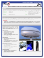
ComCenter-II ‘Outdoor’ Product Manual
Overview
Unpacking
Preparation
Installation
Operation
Warranty
Appendix
Table of Contents
Overview .................................................................................................................................................................................................2
Contacts ...................................................................................................................................................................................................2
Preface .....................................................................................................................................................................................................2
Product Features .....................................................................................................................................................................................2
Safety Information ....................................................................................................................................................................................3
Un-Packing ..............................................................................................................................................................................................6
In Case of Damages or Missing Parts ......................................................................................................................................................6
What’s Inside the Box ...............................................................................................................................................................................6
Tools Required for Installation .................................................................................................................................................................6
Preparation ..............................................................................................................................................................................................7
Pre-Use Testing of Components & Connectivity .......................................................................................................................................7
Accessing Internal SIM Slot ...................................................................................................................................................................7
Installing SIM Card .................................................................................................................................................................................7
Re-Assembling ComCenter Casing .......................................................................................................................................................7
Locating Satellite-Viewable Work Area ...............................................................................................................................................8
Attaching Phone and Power ..................................................................................................................................................................8
Activating and Testing System ................................................................................................................................................................8
Installation ...............................................................................................................................................................................................9
Attaching Bracket to Pole ........................................................................................................................................................................9
Routing Cables .........................................................................................................................................................................................9
Connecting the ComCenter ...................................................................................................................................................................9
Attaching Cable to ComCenter ...............................................................................................................................................................10
Attaching ComCenter to Bracket ..........................................................................................................................................................10
Attaching Power and Phones to Wall Plate .............................................................................................................................................10
Operation ...............................................................................................................................................................................................11
Typical Start-Up Sequence (Overview) ..................................................................................................................................................11
Power-On Confirmation .........................................................................................................................................................................11
Ready-For-Use Confirmation ................................................................................................................................................................11
Connecting To Your Computer Or Network Via Ethernet .........................................................................................................................12
Changing Modes ...................................................................................................................................................................................12
Finding your ComCenter With ASE Device Manager .........................................................................................................................13
Changing the Ethernet Connection Mode Using POTS/RJ-11 .............................................................................................................14
Changing the Ethernet Connection Mode Using Embedded Webpage ...............................................................................................14
Accessing System Settings ...................................................................................................................................................................15
Accessing ComCenter II Settings .........................................................................................................................................................16
Accessing ComCenter II Settings and Features ....................................................................................................................................17
General Use - Voice Calls ...................................................................................................................................................................18
General Use - Text Messaging ............................................................................................................................................................19
General Use - Data Calls ....................................................................................................................................................................19
Special Features ..................................................................................................................................................................................20
Specifications .......................................................................................................................................................................................23
Appendix ...............................................................................................................................................................................................24
Status and Error Tones ..........................................................................................................................................................................24
Warranty ...............................................................................................................................................................................................25
Declaration of Conformity ......................................................................................................................................................................27
REV-3.0 [3-17-11]
1
ComCenter-II ‘Outdoor’ Product Manual
Overview
Unpacking
Preparation
Installation
Operation
Warranty
Appendix
Contacts
For additional information about this Product warranty, repair service, or airtime services, please contact your Service
Provider or Point-of-Sale. For additional information about ASE products and services, please contact ASE as follows:
Telephone:
Facsimile:
480.443.1424
480.452.0971
Website:
www.ase-corp.com
Mail:
Applied Satellite Engineering, Inc.
16559 North 92nd Street, Suite 101
Scottsdale, Arizona 85260 USA
E-mail: [email protected]
Preface
ASE’s ComCenter-II ‘Outdoor’ provides an interface between the Iridium satellite network and standard POTS/
RJ-11 telephone handsets and PABX equipment for voice, and IP (Internet Protocol) for data.
QUESTIONS
If at any time, you have questions or concerns about either the installation or operation of your ComCenter,
please visit www.ase-corp.com or contact us using the information located on the cover of this manual.
Product Features
In addition to providing an uplink to the Iridium
Satellite network for both Voice and Data,
The ASE ComCenter ‘Outdoor’ also provides
satellite communication users with:
Voice Features
• Indoor Satellite Phone Usage
• Extended 2-wire RJ-11/POTS
connections up to 3Km
• Special tone sequences indicate normal
and adverse conditions
• SmartDial Dialing Sequence
Data Features
• Data Connectivity using Ethernet
Infrastructure
• AT Commands for direct modem control
• Port forwarding for IP-based control of
remote equipment
Administrative Features
• A PC-Based user console for system
setup and status
• Captain/Crew PIN Codes assignments
for multi-user authorization
• Scratch card support
Physical Features
• Small and compact size with built-in
antenna simplifies installation
• Pole or surface mount
• Rated for outdoor exposure
REV-3.0 [3-17-11]
2
ComCenter-II ‘Outdoor’ Product Manual
Overview
Unpacking
Preparation
Installation
Operation
Warranty
Appendix
PRECAUTIONS:
Please read and understand this User’s Manual before installing your ComCenter. Careless or incorrect
installation can degrade performance, damage both new and existing equipment, and incur unexpected
network airtime charges.
Safety Information
1. FAA Regulations
ASE products are NOT FAA-approved and are NOT intended for aircraft use.
2. Exposure to Radio Frequency Signals
Your Iridium-designed satellite unit is a low power radio transmitter and receiver. When it is ON, it receives
and sends out radio frequency (RF) signals.
International agencies have set standards and recommendations for the protection of public exposure to RF
electromagnetic energy:
• International Commission on Non-Ionizing Radiation Protection (ICNIRP) 1996
• Verband Deutscher Elektrotechniker (VDE) DIN-0848
• United States Federal Commission, Radio Frequency Exposure Guidelines (1996)
• National Radiological Protection Board of the United Kingdom, GS 11, 1988
• American National Standards Institute (ANSI) IEEE C95, 1-1992
• National Council on Radiation Protection and Measurements (NCRP) Report 86
• Department of Health and Welfare Canada, Safety Code 6
These standards are based on extensive scientific review. For example, over 120 scientists, engineers,
and physicians from universities, government health agencies, and industry reviewed the available body of
research to develop the updated ANSI standard.
The design of your phone complies with these standards when used as described under “Unit Operation.”
3. Unit Operation
Do not operate the unit when a person is within 4 inches (10 centimeters) of the antenna. A person or object
within 4 inches (10 centimeters) of the antenna could impair call quality and may cause the unit to operate
at a higher power level than necessary and expose that person to RF energy in excess of that established
by the FCC RF Exposure Guidelines.
4. Driving
Check the laws and regulations on the use of wireless telephones in the areas where you drive. Always obey
them. Observe the following guidelines when using your phone while driving:
•Give full attention to driving; driving safely is your first responsibility.
•Use hands-free phone operation, if available.
•Pull off the road and park before making or answering a call if driving conditions so require.
5. Electronic Devices
Most modern electronic equipment is shielded from RF signals. However, certain equipment may not be
shielded against RF signals from your Iridium-designed satellite unit.
REV-3.0 [3-17-11]
3
ComCenter-II ‘Outdoor’ Product Manual
Overview
Unpacking
Preparation
Installation
Operation
Warranty
Appendix
Safety Information (Continued)
6. Pacemakers
The Health Industry Manufacturers Association recommends that a minimum separation of 6 inches be
maintained between a wireless phone’s antenna and a pacemaker to avoid potential interference with the
pacemaker. These recommendations are consistent with the independent research by and recommendations
of Wireless Technology Research.
PERSONS WITH PACEMAKERS
•
•
Should ALWAYS keep the Iridium-designed satellite unit more than six inches from their pacemaker
when the unit is turned ON.
Should turn the unit OFF immediately if you have any reason to suspect that interference is taking
place.
7. Other Medical Devices
If you use any other personal medical device, consult the manufacturer of your device to determine if it is
adequately shielded from external RF energy. Your physician may be able to assist you in obtaining this
information.
Turn your unit OFF in health care facilities when any regulations posted in these areas instruct you to do so.
Hospitals or health care facilities may be using equipment that could be sensitive to external RF energy.
8. Vehicles
RF signals may affect improperly installed or inadequately shielded electronic systems in motor vehicles.
Check with the manufacturer or its representative regarding your vehicle. You should also consult the
manufacturer of any equipment that has been added to your vehicle.
9. Posted Facilities
Turn your unit OFF in any facilities where posted notices so require.
10. Blasting Areas
To avoid interfering with blasting operations, turn your unit OFF when in a “blasting area” or in areas posted
“Turn off two-way radio.” Obey all signs and instructions.
11. Potentially Explosive Atmospheres
Turn your unit OFF and disconnect the power supply when you are in any area with a potentially explosive
atmosphere. Obey all signs and instructions. Sparks from your battery or power source in such areas could
cause an explosion or fire resulting in bodily injury or even death.
Areas with a potentially explosive atmosphere are not always clearly marked. They include, but are not
limited to: fueling areas such as gasoline stations; below deck on boats; fuel or chemical transfer or storage
facilities; areas where fuel odors are present (for example, if a gas/propane leak occurs in a car or home);
areas where the air contains chemicals or particles, such as grain, dust, or metal powders; and any other
area where you normally would be advised to turn off your vehicle engine.
12. For Vehicles Equipped With Airbags
An air bag inflates with great force. Do NOT place objects, including both installed or portable wireless
equipment, in the area over the air bag or in the air bag deployment area. If in-vehicle wireless equipment
is improperly installed and the air bag inflates, serious injury could result.
REV-3.0 [3-17-11]
4
ComCenter-II ‘Outdoor’ Product Manual
Overview
Unpacking
Preparation
Installation
Operation
Warranty
Appendix
Safety Information (Continued)
13. Important Notes for PABX System Users
If using the ComCenter with a PABX system, the following precautions must be followed to prevent damage
to your unit.
The ComCenter emulates a standard land-line wall jack and generates the required operating and ringing
voltages. Connect to a PABX as either a central office (CO) or trunk line. Never connect the ComCenter to a
PABX as an extension or damage to the PABX or ComCenter may result.
REV-3.0 [3-17-11]
5
ComCenter-II ‘Outdoor’ Product Manual
Overview
Unpacking
Preparation
Installation
Operation
Warranty
Appendix
In Case of Damages or Missing Parts
Your ComCenter carton should contain everything needed to install the system. If you find that any component
(listed below) is missing or damaged, please contact ASE immediately.
IMPORTANT:
The ASE ComCenter ‘Outdoor’ does NOT include the mounting pole, as the length of this component will vary widely.
What’s Inside the Box
A
B
C
D
E
F
G
*
ComCenter IIG / Outdoor Unit
Communications Cable
Universal Wallplate
AC/DC power adapter: Universal
AC input / 24VDC, 15W output
Pole Mount Adapter &
Hardware
Installation CD
Product Manual
20 Foot Interface Cable
with cable to connector
breakout (RJ-11, RJ-45,
Power)
A
F
* Item not shown in Illustration
Optional
B
50 to 100 foot
extensions allow up
to 400 foot lengths
C
G
E
D
Tools Required for Installation
For this installation you will need a safe work area that is outdoors with a 360 degree view of the sky (for device testing
along with a few tools including a #2 Phillips screwdriver, a 2mm Allen Wrench, and possibly a stable Ladder.
REV-3.0 [3-17-11]
6
ComCenter-II ‘Outdoor’ Product Manual
Overview
Unpacking
Preparation
Installation
Operation
Warranty
Appendix
Pre-Use Testing of Components and Connectivity
Before spending the time to fully install the Comcenter in its new home, its best to test the components and
connectivity while all of the parts are still easily accessible.
IMPORTANT:
THE FOLLOWING STEPS ARE NOT TYPICALLY AN END USER REQUIREMENT, THE SIM CARD SHOULD BE
PRE-CONFIGURED (UNLOCKED) AND INSTALLED BY YOUR SERVICE PROVIDER.
Accessing Internal SIM Slot
Open the Top cover from the ComCenter by
removing the screws in the body as shown.
Lightly squeezing the top shell will break the
seal with the waterproof gasket and allow
access to the interior.
NOTE:
This device will be shipped to the distributor WITHOUT the screws installed. The
screws can be found inside a plastic bag.
After installing the SIM card, it is very important that the screws are located and
installed.
Installing SIM Card
Remove the SIM door using a screwdriver;
and then place the unlocked SIM card into
the slot as shown.
IMPORTANT:
Make sure to “lock” the SIM holder by
gently pushing it in the direction indicated
by the arrow.
IMPORTANT:
The modem in your ComCenter may not
be identical to that pictured here
Re-Assembling ComCenter Casing
Once the SIM card has been installed, close
the SIM door and lock it with the provided
screws. Next re-attach the top shell taking
care that the waterproof gasket seals
properly as shown. Screw down the casing
fasteners only once the gasket is properly
seated.
IMPORTANT:
Be sure that the rubber seal is properly
seated before re-tightening the Casing
Screws.
REV-3.0 [3-17-11]
7
ComCenter-II ‘Outdoor’ Product Manual
Overview
Unpacking
Preparation
Installation
Operation
Warranty
Appendix
Pre-Use Testing of Components and Connectivity (Continued)
The next step in the Pre-Use Test Process will be to connect the power and at least one telephone handset. This will allow
you to double check that the unit, and your cables, will perform properly once fully installed.
Locating Satellite-Viewable Work Area
To properly test the system, you’ll need to
place the antenna unit in a position with a
360 degree view of the sky. Any obstructions
will cause a lapse in connectivity between
the ComCenter and the orbiting satellites.
Run the cable to the supplied adapter (see
below)
Attaching Phone and Power
If you intend to use the supplied power
transformer, then connect the power jack the
wall plate as shown in the top illustration. If
you prefer to connect the system to another
DC power source*, then simply separate the
wires as shown in the bottom illustration and
connect those to the alternate source.
Next connect a standard analog/POTS
telephone into the RJ11 jack.
*24 - 36VDC, 15 Watts
Activating and Testing the System
Once the initialization has completed (about 30 seconds), you should hear one of
the following tone patterns (depending on your system settings).
[Long] (Constant Dialtone) or
[Pause]-[Short]-[Pause]........ [Found Home Network]
[Waiting for PIN code]
This indicates that all elements of the system are operating properly If any element
of the system is not operating correctly, the earpiece will emit a ‘fault code’.. Refer
to Appendix A for code definitions and the troubleshooting steps to resolve them.
NOTE:
At this point, you should be able to pick up the Handset and hear a tone
pattern. If not, you should check all your connections and try again.
IMPORTANT:
For a complete listing of the meaning behind system tone messages, see Appendix A.
REV-3.0 [3-17-11]
8
ComCenter-II ‘Outdoor’ Product Manual
Overview
Unpacking
Preparation
Installation
Operation
Warranty
Appendix
Installation
Once you have successfully “Pre-Use” tested the ComCenter device, you will be ready to proceed with system
instalation. Step-by-Step illustrations for this process are provided below.
Attaching Bracket to Pole
Attach the ComCenter mounting bracket to
the top of a Threaded 1” diameter pipe by
spinning the bracket clockwise. Once the
bracket no longer turns freely, lock it in place
using the set-screw as shown.
NOTE:
Usable Mounting Poles measure 1” in
Diameter and are end-threaded with
a 14 thread-per-inch thread.
Routing Cables
Feed the Communications cable down the bracket (and pipe) toward your
designated communications area. It is important to leave yourself 6-8” of extra
cable that will serve as a service loop while attaching the ComCenter Outdoor
Unit.
IMPORTANT:
Be sure the exposed cable contains the “Female” connector, and not the “Male”.
Connecting the ComCenter
Pull the opposite end of the communications
cable through the wall and attach it to the
supplied wall-plate adapter. Next attach the
wall-plate to the wall as shown.
IMPORTANT:
Be sure the exposed cable contains the
“Male” connector, and not the “Female”.
REV-3.0 [3-17-11]
9
ComCenter-II ‘Outdoor’ Product Manual
Overview
Unpacking
Preparation
Installation
Operation
Warranty
Appendix
Installation (continued)
The next steps in the installation process involve making all of the final cable connections and mounting the
ComCenter Outdoor Device to the newly assembled mounting bracket.
Attaching Cable to ComCenter
Plug the Female end of the communications
cable to the underside of the ComCenter
Outdoor unit. The cable is “keyed” to allow
proper pin alignment, gently rotate the plug
until it slides into place with a tactile “click”.
IMPORTANT:
Be careful not to bend pins.
Attaching ComCenter to Bracket
Once aligned, tighten the mounting screws in the bracket to the underside of the
ComCenter Outdoor Unit.
IMPORTANT:
The ComCenter Outdoor must be installed and oriented horizontally as shown
for proper satellite visibility.
Attaching Power and Phones to Wall Plate
Now that the device is fully installed, plug
in the standard telephone handset, the
CAT-5 Communications Cable, and finally
the power Supply Cable as shown. Confirm
(again) proper connectivity by listening for
the tone patterns in the handset.
If you do NOT have a steady dial tone, you
should first check all of your connections
and try again.
NOTE:
At this point, you should be able to pick up the Handset and hear a steady Dial Tone. If not, see troubleshooting
in Appendix A
REV-3.0 [3-17-11]
10
ComCenter-II ‘Outdoor’ Product Manual
Overview
Unpacking
Preparation
Installation
Operation
Warranty
Appendix
Typical Start-Up Sequence
The following guide describes the basic functions of the Applied Satellite Engineering ComCenter.
IMPORTANT:
Visit www.ase-corp.com for the latest updates. For further information or clarification, Please contact your service
provider. Your service Provider’s tech support number should be included with the shipment.
Power-On Confirmation
Searching for Network (Standard Telephone Handset)
Within 10 seconds after power-up, you should hear a tone pattern through the standard
telephone handset; this indicates that the system is searching for the Iridium network.
[Long]-[Short]........ [Searching for Network]
Registered with Network (Standard Telephone Handset)
Once the ComCenter has established a network connection to the Iridium Satellite
Network, you will then hear the following:
[Short]-[Short]-[Short]-[Short]-[Short]
[Found Home Network]
Ready-For-Use Confirmation
System Ready (Standard Telephone Handset)
Once system is ready to accept a dial request, you will hear dial tone or a pin code tone.
[Long] (Constant) [Found Home Network]
[Pause]-[Short]-[Pause]........ [Waiting for PIN code]
IMPORTANT:
For a complete listing of the meaning behind system tone messages, see Appendix A.
REV-3.0 [3-17-11]
11
ComCenter-II ‘Outdoor’ Product Manual
Overview
Unpacking
Preparation
Installation
Operation
Warranty
Appendix
CONNECTING TO YOUR COMPUTER OR NETWORK VIA ETHERNET (RJ-45)
The ComCenter II’s Ethernet port provides a powerful IP-addressable data connection to your local area network
(LAN) or directly to your computer. For maximum connection flexibility, the ComCenter II supports the following
connection options;
1. DIRECT or fixed IP address for advanced users.
2. DHCP CLIENT for automatic network integration (default).
3. DHCP SERVER for direct PC or Laptop connection.
DIRECT MODE
For single node or networks with fixed IP addresses
The direct mode allows you to manually assign a fixed IP address to the ComCenter II. The ComCenter II’s
default IP address is 192.168.1.100 but can be changed if needed. Direct mode is typically for advanced users
who need to assign specific IP addresses to support their network configuration.
DHCP CLIENT MODE
For multi-node networks that have a DHCP server (router)
This is the most common network connection mode. You connect the ComCenter II to your network like any
other Ethernet device and it gets assigned an IP address automatically. This is typically done by an Ethernet
router in the network that also provides this DHCP server function.
DHCP SERVER MODE
For single node / multi-node networks w/o a router or other DHCP server
In this mode, the ComCenter II assigns IP addresses to network peripherals, normally done by an Ethernet
router, and retains its own default IP address of 192.168.1.100. This mode is a convenient way to connect
directly to a laptop without the need for a router.
CHANGING MODES
The default mode is DHCP Client but can be changed in the following ways;
1.
Entering codes with the connected POTS/RJ-11 equipment
2.
Clicking on the desired mode via the embedded webpage.
REV-3.0 [3-17-11]
12
ComCenter-II ‘Outdoor’ Product Manual
Overview
Unpacking
Preparation
Installation
Operation
Warranty
Appendix
Finding your ComCenter II with ASE Device Manager
The ASE Device Manager utility is included with your ComCenter II
on CD-ROM. Install on your host computer and let the ASE Device
Manager simplify your network installation.
Simply click the FIND button and the ASE Device Manager will
scan your network for ASE Devices. Found device(s) will then be
listed in the drop-down Profile box. You can now select the device
from the profile box and open its unique webpage to access its
data features, or connect your PC to the Internet directly through
the device.
REV-3.0 [3-17-11]
13
ComCenter-II ‘Outdoor’ Product Manual
Overview
Unpacking
Preparation
Installation
Operation
Warranty
Appendix
Changing the Ethernet Connection Mode Using POTS/RJ-11:
The Ethernet Connection Mode can be changed via the connected POTS/
RJ-11 equipment. Listen to audible beeps to confirm the mode setting. To
change mode, take the POTS/RJ-11 phone off-hook and press the following
keys;
*610 = DIRECT (1 beep)
*611 = DHCP Client (2 beeps)
*612 = DHCP Server (3 beeps)
Additional useful commands using POTS/RJ-11;
*994 gives audible beeps according to mode setting.
Changing the Ethernet Connection Mode Using Embedded Webpage:
Accessing the embedded webpage in the ComCenter II may not be possible unless the default DHCP Client
mode is compatible with your specific network. Once you are able to access the ComCenter II’s webpage,
the mode can be changed by clicking on the CONFIGURE button. This page will allow you to change modes.
CAUTION: changing modes will likely cause you to lose access to the webpage until the network or direct
connection is also configured to this new mode.
REV-3.0 [3-17-11]
14
ComCenter-II ‘Outdoor’ Product Manual
Overview
Unpacking
Preparation
Installation
Operation
Warranty
Appendix
Accessing System Settings
System settings can be accessed and changed in several ways to allow access depending on what interface(s) you are
using.
Changeable settings include;
SmartDial 911 USA
Crew ID protected access
Captain’s card installed
Periodic reporting
PBX Answer Signaling
Voice volume adjust (POTS/RJ11 access only)
Event log and diagnostic monitoring (embedded webpage only)
Restore to factory defaults
The embedded webpage provides simple selection and dialog boxes for easy setting changes. Many of these settings can
also be accessed and changed via the RJ-11/POTS connected equipment.
REV-3.0 [3-17-11]
15
ComCenter-II ‘Outdoor’ Product Manual
Overview
Unpacking
Preparation
Installation
Operation
Warranty
Appendix
Accessing ComCenter II Settings (RJ-11)
OPTION
Volume
SEQUENCE
*
20
DESCRIPTION
1
2
3
4
5
Lowest
Press *20 and then press 1 through 5 to change the volume level sent
to the handset. Press 1 to adjust the volume to its lowest level, and 5
to adjust it to its highest.
Highest
US 911
*
50
0
1
Disabled
Enabled
Press *500 to toggle USA 911 dialing off and *501 to toggle it on.
By default the ComCenter II is set to USA 911 On. We strongly
recommend leaving 911 dialing on if you are a United States customer.
Be sure to read the sections below discussing emergency 911 calls.
This setting partially overrides SmartDial recognition of country codes
and allows United States callers to simply type 911 to access the
emergency system. (If this setting is off, then calls starting with “91”
are recognized as dialing the country code for India.)
Captain’s Sim
*
53
0
1
Disabled
Enabled
Press *530 for standard SIM card. Press *531 for Captain’s SIM.
PBX Answer
Signaling
*
54
0
1
Disabled
Enabled
Signals PBX when call connects by battery reversal
Network Mode
*
61
0
1
2
Direct
Client
Server
Sets the network mode with 0 being DIRECT, 1 being DHCP Client
and 2 being DHCP Server
###
Press *7 to reach the Phone Book that resides in the SIM card, then
enter the three-digit QuickDial number for the entry you wish to dial.
Hang up to exit this menu.
Phone Book
*
7
,
Send GPS Location
*
9
1
1
Sends GPS coordinates to the e-mail address in the Periodic Message
destination field
Network Mode
*
9
9
4
Press *994 for audible beeps that indicates the IP Mode setting.
Direct = 1 beep
DHCP Client = 2 beeps
DHCP Server = 3 beeps
Turn PIN off
Restore Defaults
REV-3.0 [3-17-11]
*
*
1
1
1
2
1
3
Unlocks SIM by turning the default Iridium PIN code off. The ComCenter
II requires the PIN be turned off to access the satellites.
1
4
5
Restores default settings (excluding network settings)
16
ComCenter-II ‘Outdoor’ Product Manual
Overview
Unpacking
Preparation
Installation
Operation
Warranty
Appendix
Accessing ComCenter II Settings and Features (Embedded Webpage)
Once connected to your network or computer, the ComCenter II’s internal webpages provide access to many features
and settings.
The images below give a general overview of just a couple of the internal pages where you can access settings and
features. Navigation between the internal pages is via simple mouse clicks, so not all pages are shown in this document.
Webpage Features include:
• ASE Satchat text messaging
• Single click Internet connection
• Periodic Messaging with optional GPS coordinates
• PIN access codes for crew calling
• IP modem control and port forwarding
• General system settings and diagnostics
See “Special Features” for additional details.
REV-3.0 [3-17-11]
17
ComCenter-II ‘Outdoor’ Product Manual
Overview
Unpacking
Preparation
Installation
Operation
Warranty
Appendix
General Use - Voice Calls
ASE’s SmartDial technology makes dialing simple. SmartDial automatically identifies the country code and
knows how many digits are required for that country code. Once the correct number of digits have been entered,
dialing commences automatically. SmartDial de-activates itself when the standard ‘00’ Iridium dialing sequence
is detected. Pressing “#” to send is then required to initiate the call.
•
Placing a call with POTS/RJ-11 Take the POTS/RJ-11 phone off-hook and listen for dial tone. When
dial tone is present, simply enter the country code, area code, and phone number. SmartDial will automatically place the call when the correct number of digits are entered and you will hear the Iridium ‘boop’
sound until the call connects.
Examples using SmartDial:
USA call: 1(3-digit area code)(7-digit phone number)
Iridium ISU call: 8816(8-digit phone number)
Examples bypassing SmartDial:
USA call: 001(3-digit area code)(7-digit phone number)(# to send)
Iridium ISU call: 0118816(8-digit phone number)(# to send)
•
Answering a call with POTS/RJ-11 POTS/RJ-11 phone connected to the ComCenter II will automatically ring
when an incoming call is pending. Simply take off-hook to answer.
REV-3.0 [3-17-11]
18
ComCenter-II ‘Outdoor’ Product Manual
Overview
Unpacking
Preparation
Installation
Operation
Warranty
Appendix
General Use - Text Messaging
•
Text messaging with ASE SatChat ASE’s powerful and convenient SatChat provides simple SMS text
messaging dialogue from any Ethernet connected device such as network computers, wireless laptops, and
even iPhones, and iPads. This included feature is available by accessing the ComCenter II’s embedded
webpage and works similar to short email messages and blog dialogues. ASE Satchat messages can be
sent to and received from other SMS enabled Iridium equipment and cell phones, as well as standard email
addresses.
General Use - Data Calls
The ComCenter II simplifies data connections via its embedded webpage. Depending on the type of connection, a simple button click from this webpage will initiate an Iridium PPP session or peer-to-peer connection.
Port forwarding features are also available for advanced users.
REV-3.0 [3-17-11]
19
ComCenter-II ‘Outdoor’ Product Manual
Overview
Unpacking
Preparation
Installation
Operation
Warranty
Appendix
SPECIAL FEATURES
POTS/RJ-11 PORT
This port provides a versatile satellite link to the standard equipment you’re already familiar with. RJ-11 connected
equipment can be located more than a mile away from the ComCenter II, solving antenna location problems and
minimizing costly antenna runs.
Besides being a voice link, this interface has the following additional features;
·
·
·
·
·
VOICE CONNECT WITH SMARTDIAL. SmartDial simplifies satellite dialing sequences by converting
familiar land line dialing to satellite dialing. But if you prefer satellite dialing, SmartDial will automatically
detect and disable itself.
PABX & WIRELESS BASE STATION. Typical RJ-11 applications include trunk line interface to standard
multi-user PABX systems, base station with single or multiple wireless handsets, or a single analog phone
powered entirely by the ComCenter II for resilience planning communications back up.
ACCESS TO SYSTEM SETTINGS. ComCenter II system configuration and settings are accessible via this
port.
STATUS AND ERROR TONES. Since most RJ-11 connected equipment is located a great distance from the
ComCenter II, specific audible tones let you know system status at all times.
INSTANT GPS POSITION REPORT. Pressing *911 from a 2-wire RJ-11 phone immediately sends a GPS
position report to the e-mail address in the Periodic Messaging delivery field.
ETHERNET PORT
This port opens up tremendous network and peripheral connection possibilities. Ethernet connection to the ComCenter II
also gives you access to unique features and applications contained in its internal webpage. Features of this port include;
·
·
·
·
·
·
·
·
DATA CONNECT WITH ASE WEBPAGE. Use your favorite web browser to access the ComCenter II’s
embedded webpage. Data connections from the ComCenter II’s webpage take just a simple click of the
mouse.
DIRECT & WIRELESS ROUTER CONNECT. Connect directly to a single computer, drop onto your network,
or use a wireless router for optimum convenience.
ASE SATCHAT. Simple yet powerful SMS text messaging application available from the embedded webpage.
ASE PORT FORWARDING. This special feature requires two ComCenter IIs in most cases to easily solve
difficult Iridium-linked M2M applications. Details are beyond the scope of this manual. Please contact ASE
for more information.
SECURITY PIN CODES. Another feature included in the embedded webpage is the option to set PIN codes
to prevent unauthorized use. Voice and data access become disabled and the ComCenter II will then prompt
the user for a valid PIN code.
STATUS AND ERROR DISPLAY. The ComCenter II’s embedded webpage has a real time status bar
showing current state of the system and Iridium network.
ACCESS TO SYSTEM SETTINGS AND DIAGNOSTICS. ComCenter II system configuration and settings
are accessible via the embedded webpage. This webpage also includes diagnostics and system logs useful
for installation confirmation and general use stats.
AT COMMANDS. Third party integrators can connect directly to a TCP/IP socket (<xxx.xxx.xxx.xxx:23>) and
execute AT Commands to directly control the modem. Contact ASE for complete AT Command Set.
REV-3.0 [3-17-11]
20
ComCenter-II ‘Outdoor’ Product Manual
Overview
Unpacking
Preparation
Installation
Operation
Warranty
Appendix
SPECIAL FEATURES (continued)
EMBEDDED WEB PAGE
As an extension of the Ethernet port, the ComCenter II provides unique and power features via its internal,
embedded web pages. System information is displayed in the header of all web pages, including; system
IMEI, Firmware Versions, Your Phone Number (see setting Your Phone Number below) and the current
System Status.
The Embedded web pages provide the following ASE special features;
·
·
·
·
·
·
·
·
·
·
·
·
·
·
·
ASE SATCHAT: Provides SMS chatting service to other Iridium phones, email addresses or cell phones
(check with cell phone provider for international support).
ASE IRIDIUM-IRIDIUM CONNECT: Initiates an internet connection via the Iridium ISP. The ComCenter II
will perform the dial-up and PPP authentication. Once status reports ONLINE you have established your
Internet Connection.
ASE COMCENTER SETUP: Provides system configuration including your phone number, periodic
messages, configuration options, and user PIN codes. Further and advanced setup options are available if
you proceed to the MODEM web-link. Note: When PIN Access Required is set to ON, access to this page
requires one of the 10 user set PIN codes previously setup on this page.
SAVE AND RESTORE: You must click save to accept all changes to the configuration. Restore will restore
the factory default configuration.
YOUR PHONE NUMBER: During installation of your ComCenter, enter Your Phone Number as a convenient
method to store this number.
INSTANT GPS POSITION REPORT / PERIODIC MESSAGES: Enter an e-mail address for Periodic
Messages and Instant GPS Position Reports. Note SMS messages may incur extra airtime charges. Check
with your service provider for more information. For Periodic Messaging, GPS coordinates can be included
in the report (MC05G model only) by typing “(GPS)” as the first characters in the periodic message.
PIN ACCESS REQUIRED: [On | Off] Activates ComCenter II PIN codes as described below.
HANDSET VOLUME: [5 Levels]
CAPTAINS CARD: [Yes | No] If your SIM card is the type called “Captain’s Card”, then this option must be
set.
USA 911: [On | Off] Allows 911 calls in US. Note: 911 conflicts with country code for India. If using SmartDial
pattern for calls to India, the USA911 can be turned off.
PIN CODES: These assigned PIN Codes allow Post-paid access to the Iridium service for systems using a
SIM card type “Captain’s Card”. The PIN must be a 7-digit number. If fewer digits are stored, the system
expects pre-pended 0’s to complete the 7-digits. For example: PIN 85260 would require entering 0085260
when accessing system.
ASE PEER-TO-PEER: Provides Peer-to-Peer configuration and connection. Setup includes Dial-up number,
or RAS (Remote Answer) enable, and Port Forwarding.
SAVE : You must click save to accept all changes to the configuration.
DIAL-UP NUMBER: This is the number of the device to be called when using this modem as the calling
device (MO) when initiating a Peer-to-Peer session.
RAS: Enable the Remote Answer Service in the modem when using this modem as the called device (MT)
in a Peer-to-Peer session.
REV-3.0 [3-17-11]
21
ComCenter-II ‘Outdoor’ Product Manual
Overview
Unpacking
Preparation
Installation
Operation
Warranty
Appendix
SPECIAL FEATURES (continued)
·
·
·
·
PORT FORWARDING: IP addresses within the local network of the remote site can be accessed using Port
Forwarding by assigning local IP addresses to unique ports. The syntax is WanPort, Local IP address:Port.
For example to allow port forward access to a web-server running on local device 192.168.1.52:80, the setup
would be 80,192.1.52:80.
ASE EVENT LOG: Displays a list of the last 100 system events. These events include phone usage and
SMS usage.
ASE NETWORK MONITOR: Updates list of signal strength and other system status information every 15
seconds.
RESTART SYSTEM: Provides a mechanism for remote system reboot.
REV-3.0 [3-17-11]
22
ComCenter-II ‘Outdoor’ Product Manual
Overview
Unpacking
Preparation
Installation
Operation
Warranty
Appendix
SPECIFICATIONS
Interface Cable Lengths (Max)
Internal Iridium Antenna Specifications
RJ-11 (Voice) Ethernet (Data) Power Frequency Range Return Loss (Min) Gain (Weighted Ave. Min)
Min Horizon Gain Nominal Impedance Polarization Basic Pattern 8,000 feet
400 feet
400 feet (24-36VDC)
Electrical Specifications
Operating Voltage Power Consumption 12 - 36 VDC
4 Watts (Idle/Standby)
9 Watts ( Avg Active)
15 Watts (Peak)
Environmental Specifications
Operating Temp Range
Exposure -40ºC to +70ºC
Outdoor per IEC 60945
Mechanical Specifications
Dimensions Weight Mounting 11L x 6W x 5H inches
3.0 lbs
Pole or Surface
1616 MHz to 1626.5 MHz
9.5 dB (<2:1 VSWR)
0.00 dBic
-2.0 dBic (82º conic avg)
50
Right Hand Circular (RHCP)
Omnidirectional &
Hemispherical
Internal GPS Specifications
Signals Tracked Frequency Channels Update Rate
Report Rate
Accuracy
Horizontal Position
Velocity
Altitude
Tracking L1, C/A Code, AGPS,
SBAS, (WAAS, EGNOS)
1575.42 MHz
16
Up to 4 Hz
Configurable
< 2.5 m (1 - Sigma)
< 2.0 m (SBAS)
< 515 m/s
10,000 m (33,000 ft) max
Wide Operating Power
The ComCenter II Outdoor operates over a 12 - 36VDC range. However, for power runs greater than 25 feet, 24 - 36VDC is
recommended to compensate for any voltage losses due to extended power runs. A 24VDC, 15W power adapter is included with the
product.
REV-3.0 [3-17-11]
23
ComCenter-II ‘Outdoor’ Product Manual
Overview
Unpacking
Preparation
Installation
Operation
Warranty
Appendix
Status and Error Tones (RJ-11/POTS interface only)
DESCRIPTION
TONE NAME
TONE PATTERN
Powering Up
Initialization
NOT READY TONE
<long tone><bleep>...repeat
Searching for Network
NOT READY TONE
<long tone><bleep>...repeat
Ready to Dial
DIAL TONE
Enter ASE Access
PIN CODE
PIN CODE BEFORE DIAL
<pause><bleep>...repeat
Device on Data Call
BUSY TONE
<continuous busy tone>
Poor Signal during Call
POOR SIGNAL
Missing SIM Card
ALERT TONE + BEEP COUNT
Alert Tone + 2 beeps
Locked SIM Card
ALERT TONE + BEEP COUNT
Alert Tone + 3 beeps
Registration Denied
ALERT TONE + BEEP COUNT
Alert Tone + 4 beeps
Bad SIM Card
ALERT TONE + BEEP COUNT
Alert Tone + 5 beeps
<continuous dial tone>
<bleep><bleep>
MAINTENANCE SCHEDULE
·
·
·
·
Test system periodically to verify proper operation. Note: this procedure can be automated using the Periodic
Messaging feature
Replace large O-ring annually to prevent water ingress
Periodically clean outside surface of unit to remove any residue or contamination build up that could impair
satellite visibility.
Verify horizontal orientation of unit for optimum satellite visibility and there are no signal obstructions.
REV-3.0 [3-17-11]
24
ComCenter-II ‘Outdoor’ Product Manual
Overview
Unpacking
Preparation
Installation
Operation
Warranty
Appendix
ASE Limited Warranty
1. Coverage and Duration
Applied Satellite Engineering, Inc. (ASE) warrants that its new satellite subscriber radiotelephone products
and accessories (the “Product”) shall be free from defects in materials and workmanship for a period of
twelve (24) months from the date such Product is delivered to the first end-user purchaser or first lessee
(the “Purchaser”), or the date such Products are first placed into satellite subscriber service, whichever
occurs earliest. ASE, at its option, shall at no charge to Purchaser, either repair or replace the Product,
or refund the purchase price of a Product that does not conform to this warranty, provided the Product is
returned in accordance with the instructions set out below and within the warranty period. These remedies
are Purchaser’s exclusive remedies under this warranty. Repair may include the replacement of parts or
boards with functionally equivalent reconditioned or new parts or boards. A Product that has been repaired
or replaced is warranted for the balance of the original warranty period. A Product for which a replacement
has been provided shall become ASE’s property.
This warranty is made by ASE to the Purchaser of the Products only, and it is not assignable or transferable
by the Purchaser. This is ASE’s sole and complete warranty for the Products. ASE assumes no obligation
or liability for additions or modifications to this warranty unless made in writing and signed by an officer of
ASE. ASE does not warrant any installation, maintenance, or service of the Products not performed by ASE.
This product is covered by a U.S.A. warranty. If the Product has been sold outside of the U.S.A., ASE will
honor the U.S.A. warranty terms and conditions only. Outside of the U.S.A., any different warranty terms,
liabilities, and/or legal requirements of the country in which the Product is sold are specifically disclaimed
by ASE.
2. Conditions Not Covered By This Warranty
a) Products that are integrated, installed, maintained, or serviced in any manner other than in accordance
with the ASE user documentation furnished with or applicable to the Product.
b) Product damage caused by the use of ancillary equipment not furnished by ASE, including accessories
and peripherals.
c) Problems where the Product is used in a combination with ancillary equipment not furnished by ASE and
it is determined by ASE there is no fault with the Product.
d) Ancillary equipment not furnished by ASE that is attached to or used in connection with the Products is not
the responsibility of ASE, and all such equipment is expressly excluded from this warranty. Furthermore, ASE
does not warrant the integrated operation of the combination of the Products with any ancillary equipment
not furnished by ASE.
e) Defects or damage resulting from: use of the Product in any manner not normal or customary; misuse,
accident, or neglect, including but not limited to dropping the Product onto hard surfaces, immersion in or
exposure to water, rain or extreme humidity, immersion in or exposure to sand, dirt, or other particulates,
exposure to extreme heat, spills of food or liquid; improper testing, operation, maintenance, installation,
adjustment; or any alteration or modification of any kind.
f) Batteries manufactured by ASE and sold with Products whose capacity exceeds 80% of rated capacity
are not covered. Batteries whose capacity falls below 80% of rated capacity, or that develop leakage, shall
be considered non-conforming. This warranty is voided for batteries if: i) such batteries are charged by other
than the ASE-approved battery charger specified for charging such batteries; ii) any seals on such batteries
are broken or show evidence of tampering; iii) such batteries are used in equipment other than the Product
for which they are specified; or iv) such batteries are charged and stored at temperatures greater than 60
degrees Celsius.
g) Breakage or damage to antennas, or scratches or other damage to plastic surfaces or other externally
exposed parts caused by Purchaser’s use.
REV-3.0 [3-17-11]
25
ComCenter-II ‘Outdoor’ Product Manual
Overview
Unpacking
Preparation
Installation
Operation
Warranty
Appendix
ASE Limited Warranty (Continued)
h) Products disassembled or repaired in such a manner as to adversely affect performance or prevent
adequate inspection and testing to verify any warranty claim.
i) Products on which serial numbers or date tags have been removed, altered, or obliterated.
j) Coil cords that are stretched or on which the modular tab is broken; leather cases, which are covered
under separate manufacturer’s warranties.
k) Products rented on a month-to-month basis.
l) Normal wear and tear.
3. Obtaining Warranty Service
For warranty questions, repairs, or for the return of Product, please call your Service Provider or Point-of-Sale,
not ASE. Equipment needing service should be returned to your Service Provider or Point-of-Sale, not ASE.
SERVICE WORK PERFORMED BY SERVICE CENTERS NOT AUTHORIZED BY ASE TO PERFORM SUCH
WORK WILL VOID THIS WARRANTY.
All products shipped to ASE’s authorized Warranty Service Center must be shipped with freight and insurance
prepaid. Purchaser must include with the Product a bill of sale, a lease, or some other comparable proof of
purchase, the name and location of the installation facility, if any, and most importantly, the Purchaser’s name,
address, and telephone number and a written description of the problem. Product that is repaired or replaced
under this warranty shall be returned to Purchaser at ASE’s expense for the freight and insurance, and at
Purchaser’s expense for any applicable duties or other charges. If additional information is needed, please
contact ASE at the address and phone number listed in Paragraph 6 below.
4. General Provisions
THIS WARRANTY IS GIVEN IN LIEU OF ALL OTHER WARRANTIES EXPRESS OR IMPLIED, INCLUDING
BUT NOT LIMITED TO THE IMPLIED WARRANTIES OF MERCHANTABILITY AND FITNESS FOR A
PARTICULAR PURPOSE. FURTHER, THIS WARRANTY COVERS THE PRODUCTS ONLY, AND NO
WARRANTY IS MADE AS TO COVERAGE, AVAILABILITY, OR GRADE OF SERVICE PROVIDED BY ASE
SEPARATELY FOR ASE SATELLITE SERVICES. IN NO EVENT SHALL ASE BE LIABLE FOR DAMAGES
IN EXCESS OF THE PURCHASE PRICE OF THE PRODUCT IN QUESTION, OR FOR ANY LOSS OF USE,
LOSS OF TIME, INCONVENIENCE, COMMERCIAL LOSS, LOST PROFITS OR SAVINGS OR OTHER
INCIDENTAL, SPECIAL, OR CONSEQUENTIAL DAMAGES ARISING OUT OF THE USE OR INABILITY TO
USE SUCH PRODUCT, TO THE FULL EXTENT SUCH MAY BE DISCLAIMED BY LAW.
5. State Law and Other Jurisdiction Rights; Software Copyrights
Some states and other jurisdictions do not allow the exclusion or limitation of incidental or consequential
damages, or limitation on how long an implied warranty lasts, so the above limitations or exclusions may not
apply to Purchaser.
This warranty gives Purchaser specific legal rights, and Purchaser may also have other rights that vary from
jurisdiction to jurisdiction.
Laws in the United States and other countries preserve for ASE certain exclusive rights for copyrighted Product
software such as the exclusive rights to reproduce in copies and distribute copies of such Product software.
Product software may be copied into, used in, and redistributed with only the Product associated with such
Product software. No other use, including without limitation disassembly, of such Product software or exercise
of exclusive rights in such Product software is permitted.
REV-3.0 [3-17-11]
26
ComCenter-II ‘Outdoor’ Product Manual
Overview
Unpacking
Preparation
Installation
Operation
Warranty
Appendix
Declaration Of Conformity
REV-3.0 [3-17-11]
27