1
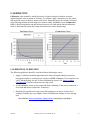
FlexiForce Sensors ® User Manual 09/23/05 Flexiforce Sensor User Manual (RevF) Table Of Contents INTRODUCTION......................................................................................................................... 3 GETTING ASSISTANCE .................................................................................................................. 3 OVERVIEW.................................................................................................................................. 4 SENSORS ...................................................................................................................................... 4 APPLICATION ............................................................................................................................... 5 SENSOR LOADING CONSIDERATIONS ............................................................................... 6 SENSOR LOADING ........................................................................................................................ 6 SATURATION ................................................................................................................................ 6 CONDITIONING SENSORS.............................................................................................................. 7 CALIBRATION............................................................................................................................ 8 CALIBRATION GUIDELINES .......................................................................................................... 8 SENSOR PERFORMANCE CHARACTERISTICS ................................................................ 9 REPEATABILITY ........................................................................................................................... 9 LINEARITY ................................................................................................................................... 9 HYSTERESIS ................................................................................................................................. 9 DRIFT ........................................................................................................................................... 9 TEMPERATURE SENSITIVITY ........................................................................................................ 9 SENSOR LIFE / DURABILITY ....................................................................................................... 10 SENSOR PROPERTIES .................................................................................................................. 10 MODEL A201.............................................................................................................................. 10 09/23/05 FlexiForce Sensor User Manual (RevF) 2 INTRODUCTION This manual describes how to use Tekscan's FlexiForce Sensors. These sensors are ideal for designers, researchers, or anyone who needs to measure forces without disturbing the dynamics of their tests. The FlexiForce sensors can be used to measure both static and dynamic forces (up to 1000 lbf.), and are thin enough to enable non-intrusive measurement. The FlexiForce sensors use a resistive-based technology. The application of a force to the active sensing area of the sensor results in a change in the resistance of the sensing element in inverse proportion to the force applied. GETTING ASSISTANCE Tekscan, Inc. will provide technical assistance for any difficulties you may experience using your FlexiForce system. Write, call or fax us with any concerns or questions. Our knowledgeable support staff will be happy to help you. Comments and suggestions are always welcome. FlexiForce a division of Tekscan, Inc. 307 West First Street South Boston, MA 02127-1309 Phone: (617) 464-4500 Fax: (617) 464-4266 E-mail: [email protected] Copyright © 2004 by Tekscan, Incorporated. All rights reserved. No part of this publication may be reproduced, transmitted, transcribed, stored in a retrieval system, or translated into any language or computer language, in any form or by any means without the prior written permission of Tekscan, Inc., 307 West First Street, South Boston, MA 02127-1309. Tekscan, Inc. makes no representation or warranties with respect to this manual. Further, Tekscan, Inc. reserves the right to make changes in the specifications of the product described within this manual at any time without notice and without obligation to notify any person of such revision or changes. FlexiForce is a registered trademarks of Tekscan, Inc. Windows 95/98/ME/2000/XP, MS-DOS, Word, Notepad, and Excel are registered trademarks of Microsoft Corporation. 09/23/05 FlexiForce Sensor User Manual (RevF) 3 OVERVIEW This section outlines Sensor Construction and Application. SENSORS The FlexiForce sensor is an ultra-thin and flexible printed circuit, which can be easily integrated into most applications. With its paper-thin construction, flexibility and force measurement ability, the FlexiForce force sensor can measure force between almost any two surfaces and is durable enough to stand up to most environments. FlexiForce has better force sensing properties, linearity, hysteresis, drift, and temperature sensitivity than any other thin-film force sensors. The "active sensing area" is a 0.375” diameter circle at the end of the sensor. The A201 sensor is available in the following force ranges: Sensor A201-1 (0-1 lb. force range) Sensor A201-25 (0-25 lb. force range) Sensor A201-100 (0-100 lb. force range)* • • • * In order to measure forces above 100 lbs. (up to 1000 lbs), apply a lower drive voltage and reduce the resistance of the feedback resistor (1kΩ min.). See the sample drive circuit below. The sensors are constructed of two layers of substrate. This substrate is composed of polyester film. On each layer, a conductive material (silver) is applied, followed by a layer of pressuresensitive ink. Adhesive is then used to laminate the two layers of substrate together to form the sensor. The silver circle on top of the pressure-sensitive ink defines the “active sensing area.” Silver extends from the sensing area to the connectors at the other end of the sensor, forming the conductive leads. FlexiForce sensors are terminated with a solderable male square pin connector, which allows them to be incorporated into a circuit. The two outer pins of the connector are active and the center pin is inactive. The length of the sensors can be trimmed by Tekscan to predefined lengths of 2”, 4” and 6” or can be trimmed by the customer. If the customer trims the sensor, a new connector must be attached. This can be accomplished by purchasing staked pin connectors and a crimping tool. A conductive epoxy can also be used to adhere small wires to each conductor. 09/23/05 FlexiForce Sensor User Manual (RevF) 4 The sensor acts as a variable resistor in an electrical circuit. When the sensor is unloaded, its resistance is very high (greater than 5 Meg-ohm); when a force is applied to the sensor, the resistance decreases. Connecting an ohmmeter to the outer two pins of the sensor connector and applying a force to the sensing area can read the change in resistance. Sensors should be stored at temperatures in the range of 15°F (-9°C) to 165°F (74°C) APPLICATION There are many ways to integrate the FlexiForce sensor into an application. One way is to incorporate it into a force-to-voltage circuit. A means of calibration must then be established to convert the output into the appropriate engineering units. Depending on the setup, an adjustment could then be done to increase or decrease the sensitivity of the sensor. An example circuit is shown below. In this case, it is driven by a -5 V DC excitation voltage. This circuit uses an inverting operational amplifier arrangement to produce an analog output based on the sensor resistance and a fixed reference resistance (RF). An analog-to-digital converter can be used to change this voltage to a digital output. In this circuit, the sensitivity of the sensor could be adjusted by changing the reference resistance (RF); a lower reference resistance will make the sensor less sensitive, and increase its active force range. In the circuit shown, the dynamic force range of the sensor can be adjusted by changing the reference resistor (RF) or by changing the Drive Voltage (VO). Refer to the Saturation section for additional information. 09/23/05 FlexiForce Sensor User Manual (RevF) 5 SENSOR LOADING CONSIDERATIONS The following general sensor loading guidelines can be applied to most applications, and will help you achieve the most accurate results from your tests. It is important that you read the Sensor Performance Characteristics section for further information on how to get the most accurate results from your sensor readings. SENSOR LOADING The entire sensing area of the FlexiForce sensor is treated as a single contact point. For this reason, the applied load should be distributed evenly across the sensing area to ensure accurate and repeatable force readings. Readings may vary slightly if the load distribution changes over the sensing area. Note that the sensing area is the silver circle on the top of the sensor only. It is also important that the sensor be loaded consistently, or in the same way each time. If the footprint of the applied load is smaller than the sensing area, the load should not be placed near the edges of the sensing area, to ensure an even load distribution. It is also important to ensure that the sensing area is the entire load path, and that the load is not supported by the area outside of the sensing area. If the footprint of the applied load is larger than the sensing area, it may be necessary to use a "puck." A puck is a piece of rigid material (smaller than the sensing area) that is placed on the sensing area to ensure that the entire load path goes through this area. The puck must not touch any of the edges of the sensing area, or these edges may support some of the load and give an erroneous reading. The FlexiForce sensor reads forces that are perpendicular to the sensor plane. Applications that impart "shear" forces could reduce the life of the sensor. If the application will place a "shear" force on the sensor, it should be protected by covering it with a more resilient material. If it is necessary to mount the sensor to a surface, it is recommended that you use tape, when possible. Adhesives may also be used, but make sure that the adhesive will not degrade the substrate (polyester) material of the sensor before using it in an application. Adhesives should not be applied to the sensing area; however, if it is necessary, ensure that the adhesive is spread evenly. Otherwise, any high spots may appear as load on the sensor. SATURATION The Saturation force is the point at which the device output no longer varies with applied force. The saturation force of each sensor is based on the maximum recommended force specified by Tekscan, which is printed on the system packaging or the actual sensor, along with the "Sensitivity." 09/23/05 FlexiForce Sensor User Manual (RevF) 6 The saturation value is based on using the circuit and the values shown in the example circuit in the ‘Application’ section. In this example, the saturation force (maximum force) of each sensor is related to the RF (reference resistance), and can be altered by changing the sensitivity. The sensitivity of the sensor would be adjusted by changing the reference resistance (RF); a lower reference resistance will make the system less sensitive, and increase its active force range. It is essential that the sensor(s) do not become saturated during testing. CONDITIONING SENSORS Exercising, or Conditioning a sensor before calibration and testing is essential in achieving accurate results. It helps to lessen the effects of drift and hysteresis. Conditioning is required for new sensors, and for sensors that have not been used for a length of time. To condition a sensor, place 110% of the test weight on the sensor, allow the sensor to stabilize, and then remove the weight. Repeat this process four or five times. The interface between the sensor and the test subject material should be the same during conditioning as during calibration and actual testing. IMPORTANT! Sensors must be properly conditioned prior to calibration and use. 09/23/05 FlexiForce Sensor User Manual (RevF) 7 CALIBRATION Calibration is the method by which the sensor’s electrical output is related to an actual engineering unit, such as pounds or Newtons. To calibrate, apply a known force to the sensor, and equate the sensor resistance output to this force. Repeat this step with a number of known forces that approximate the load range to be used in testing. Plot Force versus Conductance (1/R). A linear interpolation can then be done between zero load and the known calibration loads, to determine the actual force range that matches the sensor output range. Resistance Curve: Conductance Curve: CALIBRATION GUIDELINES The following guidelines should be considered when calibrating a sensor: • Apply a calibration load that approximates the load to be applied during system use, using dead weights or a testing device (such as an MTS or Instron). If you intend to use a "puck" during testing, also use it when calibrating the sensor. See Sensor Loading Considerations for more information on using a puck. • Avoid loading the sensor to near saturation when calibrating. If the sensor saturates at a lower load than desired, adjust the "Sensitivity." • Distribute the applied load evenly across the sensing area to ensure accurate force readings. Readings may vary slightly if the load distribution changes over the sensing area. Note: Read the Sensor Performance Characteristics section before performing a Calibration. 09/23/05 FlexiForce Sensor User Manual (RevF) 8 SENSOR PERFORMANCE CHARACTERISTICS There are a number of characteristics of sensors, which can affect your results. This section contains a description of each of these conditions, and recommendations on how to lessen their effects. REPEATABILITY Repeatability is the ability of the sensor to respond in the same way to a repeatedly applied force. As with most measurement devices, it is customary to exercise, or "condition" a sensor before calibrating it or using it for measurement. This is done to reduce the amount of change in the sensor response due to repeated loading and unloading. A sensor is conditioned by loading it to 110% of the test weight four or five times. Follow the full procedure in the Conditioning Sensors section. LINEARITY Linearity refers to the sensor’s response (digital output) to the applied load, over the range of the sensor. This response should ideally be linear; and any non-linearity of the sensor is the amount that its output deviates from this line. HYSTERESIS Hysteresis is the difference in the sensor output response during loading and unloading, at the same force. For static forces, and applications in which force is only increased, and not decreased, the effects of hysteresis are minimal. If an application includes load decreases, as well as increases, there may be error introduced by hysteresis that is not accounted for by calibration. DRIFT Drift is the change in sensor output when a constant force is applied over a period of time. If the sensor is kept under a constant load, the resistance of the sensor will continually decrease, and the output will gradually increase. It is important to take drift into account when calibrating the sensor, so that its effects can be minimized. The simplest way to accomplish this is to perform the sensor calibration in a time frame similar to that which will be used in the application. TEMPERATURE SENSITIVITY In general, your results will vary if you combine high loads on the sensor with high temperatures. To ensure accuracy, calibrate the sensor at the temperature at which it will be used in the application. If the sensor is being used at different temperatures, perform a calibration at each of these temperatures, save the calibration files, then load the appropriate calibration file when using the sensor at that temperature. 09/23/05 FlexiForce Sensor User Manual (RevF) 9 SENSOR LIFE / DURABILITY Sensor life depends on the application in which it is used. Sensors are reusable, unless used in applications in which they are subjected to severe conditions, such as against sharp edges, or shear forces. FlexiForce sensors have been successfully tested at over one million load cycles using a 50 lb. force. Rough handling of a sensor will also shorten its useful life. For example, a sensor that is repeatedly installed in a flanged joint will have a shorter life than a sensor installed in the same joint once and used to monitor loads over a prolonged period. After each installation, visually inspect your sensors for physical damage. It is also important to keep the sensing area of the sensor clean. Any deposits on this area will create uneven loading, and will cause saturation to occur at lower applied forces. Sensor Properties Operating Range 15°F (-9°C) to 140°F (60°C) Linearity (Error) <+/- 5% Repeatability Hysteresis Drift Temperature Sensitivity 09/23/05 Model A201 <+/- 2.5% of full scale (conditioned sensor, 80% force applied) <4.5% of full scale (conditioned sensor, 80% force applied) <3% per logarithmic time scale (constant load of 90% sensor rating) Output variance up to 0.2% per degree F (approximately 0.36% per degree C). For loads >10 lbs., operating temperature can be increased to 165°F (74°C). FlexiForce Sensor User Manual (RevF) 10