1
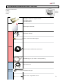
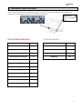
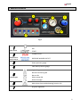
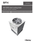
Instruction Manual Idromatic s.r.l. - via Petrarca n°127 - 46030 Borgoforte (MN) – Italy - p.iva e cod. fiscale: 02096330200 email: [email protected] - website: www.idromatic.it - tel. +39 0376 648756 - fax. +39 0376 649140 English ENGLISH WARNING! Before usage read this manual carefully and follow the instructions so as to avoid improper and dangerous (to people, animals and objects) operations while using the steamer. The manufacturer is not responsible for and reserves the right to not apply the warranty to: Damage caused by normal wear and tear, abnormal use or conditions, misuse, neglect, abuse, accident, improper handling or storage, exposure to moisture, unauthorized modifications, alterations, or repairs, improper installation, improper use of any electrical source, undue physical or electrical stress, operator error, non-compliance with instructions or other acts which are not the fault of manufacturer, including damage or loss during shipment. Certified Product Idromatic s.r.l. via Petrarca n°127 46030 Borgoforte (MN) - Italy p.iva e cod. fiscale – VAT: 02096330200 email: [email protected] website: www.idromatic.it tel. +39 0376 648756 fax. +39 0376 649140 1 English TABLE OF CONTENTS 1. PACKAGING DIMENSIONS AND CONTENTS 3 2. SPECIFICATIONS 3 3. MAIN CONTROLS AND NORMAL OPERATIONAL SIGNALS 4 4. SAFETY RULES 5 5. PRELIMINARY OPERATIONS 7 6. STEAM: GETTING STARTED 11 7. STEAM: START UP, REGULAR OPERATION AND SHUTTING DOWN 12 8. STEAM: WORKING WITH THE SANDBLASTING KIT 13 9. PRESSURE WASHER: GETTING STARTED 15 10. PRESSURE WASHER: START UP, REGULAR OPERATION AND SHUTTING DOWN 16 11. MAINTENANCE PLAN 16 12. STEAM MAINTENANCE : DESCALING 18 13. STEAM MAINTENANCE : CLEANING BOILER SENSORS 19 14. STEAM MAINTENANCE : CLEANING WATER FILTERS 20 15. STEAM MAINTENANCE : CLEANING FUEL FILTERS 21 16. STEAM MAINTENANCE : CLEANING/ADJUSTING SPARK ELECTRODES 22 17. PRESSURE WASHER MAINTENANCE 18. TROUBLESHOOTING 23 19. WIRING DIAGRAM 27 CONFORMITY DECLARATION 28 WARRANTY CONDITIONS 29 24 SAFETY STATEMENT 30 2 English 1. PACKAGING DIMENSIONS AND CONTENTS PACKAGING DIMENSIONS L=70cm W=106cm H=102 Detergent container support bracket + N°2 8x30 screws + N°2 D8 washers 5L detergent container Gun (M22 F fitting) Teflon nozzle with M22 adaptor STEAM 10m hose with rubber burn protection Sandblasting kit (for steam - sold separately) 10m HP R1 hose PRESSURE WASHER RL26 automatic gun 120cm lance + adjustable nozzle 3 English 2. TECHNICAL SPECIFICATIONS The technical specifications are written in the metal plaques as shown below, as well as the serial numbers of the machine and the boiler which will identify them uniquely. These serial numbers must be given to the reseller or the manufacturer as well whenever assistance is requested for the steamer. DIESEL STEAM GENERATOR PRESSURE WASHER Nominal operation Pressure [bar] 9 Nominal operation Pressure [bar] 140 Boiler Temperature [°C] 180 Water flow rate [l/min] 8 Outgoing temperature [°C] 150 Motor Performance [HP - kW] 3 – 2,24 Dry steam flow rate [kg/h] 33 RPM 1400 Wet steam flow rate [kg/h] 42 Voltage[V] 220 Diesel Consumption [l/h] 3.4 Power [W] 500 Voltage[V] 220 Frequency[Hz] 50 Water tank Capacity [l] 24 Fuel tank Capacity [l] 20 Pre-heating Time [min] <4 Net Weight [kg] 160 4 English 3. MAIN CONTROLS 2 7 3 1 6 4 5 Fig 1 1 Main Switch 2 Steam/Pressure washer controls 3 4 OFF ON START STEAM OUTLET PRESSURE WASHER OUTLET Steam pressure gauge Cold water pressure gauge High voltage connection 5 Indicator lights Normal functioning ON Burner ON Water pump ON Diesel shortage 6 7 Main alarm: See troubleshooting (section 14) Dry/wet regulation 5 English INDICATOR LIGHTS LIGHT Slow blinking Fast blinking + Continuous beep Continuous light + beep + Continuous light MEANING Machine is in state of stand-by, the machine is waiting for the selection of the operation mode: “SELF-CLEANING/DESCALING” (see par. 9) or “REGULAR OPERATION MODE” (see par. 7) SELF-CLEANING/DESCALING mode The boiler is filling with water. Pull the trigger on the steam gun to vent the boiler and eliminate any air (see section 7). REGULAR OPERATION MODE. During this phase more indicator lights will light up according to the specific program chosen. Connected to the electric grid. Burner ON. Pump ON. FUEL SHORTAGE ALARM Refill the machine with fuel as described in section 6h. In case you do not supply fuel in 4 or 5 minutes after the alarm sounds, the machine will give off smoke and the error lights will turn on ( ERROR 2,see section 14) 6 English 4. SAFETY RULES KEEP THIS INSTRUCTION MANUAL Before starting any operation with ASTRA STEAMER HYBRID read the following instructions carefully. Store the manual for later use or for subsequent owners. The manufacturer is not responsible for any damage caused by improper use of the machine or noncompliance with the instructions. Do not make substitutions or modifications to any of the parts of the machine The voltage indicated on the type plate must correspond to the voltage of the electrical source. The electrical grid to which the machine is connected must be made according to current National Safety Directives. Before unplugging the machine make sure that you have turned it off by the main switch 1 (fig.01) Do not pull the power cord to disconnect the machine. To avoid damaging the cord, unplug directly at the wall outlet. Make sure that the power cord or extension cables are not damaged by running over, pinching, dragging or similar. Protect the cable from heat, oil, and sharp edges. Do not use the Steamer if the power cord has been damaged. Do not use extension cords that are not approved / recommended by the manufacturer as they can increase fire hazard. Do not repair a damaged cable. If the cable needs to be substituted please contact Assistance. Never touch the electric outlet with wet hands. Do not use the machine while barefoot. Do not use the machine in proximity of full sinks, tubs, or basins. Do not submerge the machine or any of its components in water or any other liquid. It is strictly forbidden to operate the machine in areas with a potential explosion hazard. Do not use the machine in proximity of hazardous/toxic substances. Do not leave the machine on heat-sensitive surfaces while still hot. Do not leave the machine exposed to weather and environmental hazards. Do not place the machine close to ovens, stoves or any other heat source. Do not expose the machine to extreme temperatures. 7 English The appliance may only used by persons who have been instructed in handling the appliance or have proven qualification and expertise in operating the appliance or have been explicitly assigned the task of handling the appliance. The appliance must not be operated by children, young persons or persons who have not been instructed accordingly. Do not press/turn the switches with excessive strength. Always position the machine on a firm, stable surface. Make sure to block it using the brake. If the machine happens to fall or crash, please call Assistance immediately as some safety mechanisms may have been compromised. If the machine does not function properly, turn it off and do not attempt to repair it. Call Assistance immediately. During cleaning, if the waste water contains oil, make sure you are working in an area with a suitable oil treatment drainage system. Always make sure that the electric grid has an omnipolar differential circuit breaker with the following characteristics: D In 0.03ª. Always verify that the main differential circuit breaker is functioning properly. Do not come too close to the vehicle and its wheels with the steam nozzle as it can damage its safety devices. Never leave the machine unattended so long as it is running. Never leave the machine unattended in areas where vehicles may pass and damage the power cord and hose. Do not point the stream towards electronic devices. In case the machine does not function correctly switch off the machine by main switch on the left side. Do not attempt to connect tubes to the boiler exhaust. If an extension of the exhaust is needed please refer to the Idromatic PN 15.226 extension or contact Assistance for more information. High-pressure jets can be dangerous if improperly used. The jet may not be directed at persons, animals, live electrical equipment or at the appliance itself. For Car Wash purposes make sure to keep the nozzle at a distance no closer than 30cm of the automobile. Any maintenance (cleaning) operation must be done only after the following operations have been performed: The machine has unplugged The boiler has been properly drained (use drainage valve 8, fig.02) The pressure gauge reads 0 bar Wait around 30 minutes after the discharging operation to make sure the machine cools down. Remove the cover by unscrewing the placeholder screw 12 (fig.09) Only use the fuels specified in the Instruction Manual. Risk of explosion due to the use of inappropriate fuels. The use of other types of fuel will void the warranty. If the appliance is used in gas stations the corresponding safety provisions must be observed. BURN HAZARD - Do not let any body part come into contact with the steam jet. 8 English Only use water from the local water supply or softened water. DO NOT USE DISTILLED WATER. Do not use the machine is closed areas. The exhaust fumes and gases will not disperse correctly and present a health hazard. Do not touch the outlet fittings/couplings and fittings/couplings in general before letting the machine cool down. Handle the steam gun, nozzles and wands (and relative couplings) with care as they can reach high temperatures. Do not leave ASTRA STEAMER HYBRID unattended while still pressurized and hot. The proper shut down and drainage operations must be performed. Do not store ASTRA STEAMER HYBRID in places where the temperatures can go below 0°C/32F. If the machine (or any of its components) freezes, it is necessary to wait until it has thawed before using it. If the machine is to be stored in places where temperatures can go below 0°C/32F, follow the steps described in section 7e. For maintenance operations not described in this manual please contact your local vendor or the manufacturer. Do not spill oil, fuel or chemicals on the floor or near soil, water or sewage systems. When refilling the water tank it is recommended to turn off the machine and unplug the power cord. Move the machine carefully and avoid any rough movements. The machine’s functioning is protected by safety devices and sensors. Repairs and adjustments should only be performed by qualified and authorized personnel. In compliance with the 2002/95/CE, 2002/95/CE y 2003/108/CE directive, at the end of its service life the machine must be transported to a proper dismantling area. 9 English OPEN 8 Figure 02 1 Figure03 Figure 04 5 2 6 3 4 Figure 05 Figure 06 8 7 11 9 10 Figure 07 Figure 08 10 English 5. PRELIMINARY OPERATIONS IDROMATIC is not responsible for any accidents caused by improper handling/non-compliance with the instructions for use. a. VERIFY THE CONDITIONS OF THE MACHINE: Before unpacking make sure all the components are present and in good condition. In case of transport damage inform the vendor immediately. b. RETURNS: In case of returns to the manufacturer, the machine needs to be packed in its original box /pallet or its equivalent. c. VERIFY THE POWER CONNECTIONS! Make sure that your local electric grid is compatible with the machine’s characteristics (visible on the machine’s plaques and on page 3). Use plugs compliant with IEC 60634 standards. Do not use extension cords. The installation must be performed by qualified technicians in accordance with the local safety standards. Connect the main power cord 11 to a fuse-protected socket with proper earthing. Make sure the indicator light turns on . Make sure the main switch 1 (fig.01) is in the OFF position d. SECURE THE MACHINE WITH THE BRAKE: Before initiating any operation, position the machine on a firm, stable surface and secure the rear wheels 1 (fig.03). To remove the brake move the lever as in fig. 04. e. CONNECT TO AN EXTERNAL WATER SOURCE: Connect a hose from the external water source to the quick inlet fitting 9 (fig.07) using a hose clip (not included), then insert it to the machine fitting 10 (fig.07). Open the external water source tap. Use clean supply water, softened but not distilled. f. MOUNT THE DETERGENT CANISTER: If you wish to use detergent while using the pressure washer mount the CHEMIK detergent container support bracket on the side of the machine (above the serial number plaque) with the included screws (8x30) and two D8 washers. Once the support bracket is secure, place the detergent canister carefully on the bracket. 11 English 6. WORKING WITH STEAM – GETTING STARTED a. CONNECT THE STEAM HOSE TO THE MACHINE: Raise the burn-saver metal door 2 (fig.05) and connect the steam hose to the LEFT outlet 3 (fig. 05) tightening the nut using a 19mm wrench. Cover the coupling with the rubber protective cover 4 (fig.05). Plug in the hose cable as shown in the picture. b. CONNECT THE STEAM GUN TO THE HOSE: Attach the steam-gun 5 to the hose (fig.06) tightening the nut with a 19mm wrench. Shift the rubber protection 4 onto the brass fitting to prevent burns (fig. 05). c. CONNECT THE NOZZLE TO THE STEAM GUN 12 English d. FILL THE FUEL TANK: Make sure there is enough Diesel in the fuel tank (at least 5-6liters). If not, please refill the fuel tank through the inlet 7 (fig.07) making sure that the fuel used is filtered and of good quality (dirty fuel may damage the boiler, in particular the fuel pump) Refill the fuel tank only with DIESEL. Refilling the tank with dirty or diluted fuel can seriously damage the fuel pump and compromise the machine’s functioning. 7. WORKING WITH STEAM – START UP, OPERATION AND SHUTDOWN a. START UP: Rotate the switch to position 1 (fig.01) to and then release the switch. It will automatically go to position . Open the STEAM outlet by pressing the corresponding button switch on the gun (see picture below). STEAM OUTLET BUTTON ASTRA STEAMER HYBRID will automatically start to fill the boiler with water. This operation is signaled by the following: + continuous beep + . When the water in the boiler has reached a suitable level the burner will start up and will continue for approximately 2’. During this phase the burner heats the water to reach maximum temperature. During use, the machine will refill the boiler as needed, signaled by . Make sure to open and close the trigger to vent the boiler during start up. Wait until the burner indicator light has shut off before starting to operate the machine. This signals that the nominal operating pressure has been reached. The burner will continue to function for another 2’ approximately. b. REGULAR OPERATION: High-pressure jets can be dangerous if improperly used. The jet may not be directed at persons, animals, live electrical equipment or at the appliance itself. For Car Wash purposes make sure to keep the nozzle at a distance no closer than 30cm of the automobile. Press the button on the gun and use the machine following the safety precautions in section and pay attention to keep the nozzle at a minimum distance of 10cm from the surface to be cleaned. Do not point the steam jet towards face and/or body parts even if protected. During regular operation ASTRA STEAMER HYBRID will automatically maintain working conditions (temperature and pressure) by turning on the water pump and burner . 13 English In case of a 5 minute break: to reduce fuel consumption, press the steam outlet button on the gun. When resuming regular operation press the steam outlet button again to resume steam flow. c. REFILL THE FUEL TANK : If during regular use the following indicator light lights up it is necessary to refill the fuel tank. (see section 6g). In case of fuel shortage the machine will start to produce white smoke. If the machine is not refilled with fuel the ASTRA STEAMER HYBRID will be shut down by the IDROMATIC flame failure control. The recharge of fuel must be done with the main switch 1 (fig.02) in OFF position again as described in section 7a. . ; after refilling, switch on d. WET/DRY STEAM REGULATOR: In case of extremely dirty or muddy surfaces adjust the moisture regulator 3 (fig.01) clockwise (for more humid steam) as necessary. e. SHUTTING DOWN AND STORAGE: After finishing regular usage rotate main switch 1 (fig.01) to OFF (indicated by slow flashing then to ON to activate stand-by mode indicator). Make sure to drain the steam from the boiler: Let out the remaining steam by keeping the steam outlet button open. Making sure (by checking the pressure gauge) that the pressure has dropped to 0bar, open the drainage valve 8 (fig.02) while pulling the trigger to accelerate the drainage of the steam from the boiler. OPEN 8 Figure 02 When the boiler is empty turn switch 1 (fig.01) to OFF water supply hose. Store the power cord in a safe place. and unplug the machine. Disconnect the external Store ASTRA STEAMER HYBRID leaving the boiler drainage valve 8 (fig.02) open. If storing the machine in areas with freezing temperatures: If the machine is stored in areas that can be subject to freezing temperatures (0°C/32F ) make sure that, after having properly emptied the machine (see section 8e), there is no water left in the water filters. 14 English 8. WORKING WITH STEAM – USING THE SANDBLASTING KIT* If you have purchased the optional Steam Sandblasting kit please follow these instructions carefully. a. CONNECT THE SANDBLASTING LANCE TO THE STEAM GUN: Screw in the sandblasting lance when the machine has reached nominal operating pressure (9bar). b. PLACE THE SUCTION TUBE IN A RECIPIENT WITH SAND: Fill a container with sand (appropriate for sandblasting). Insert the suction tube in the container filled with sand. c. OPEN THE STEAM OUTLET Open the STEAM outlet by pressing the corresponding button switch on the gun (see picture). STEAM OUTLET BUTTON 15 *Optional kit – sold separately English 9. WORKING WITH THE PRESSURE WASHER – GETTING STARTED a. CONNECT THE R1 PRESSURE HOSE TO THE MACHINE: Before doing so purge the hose of any impurities by allowing a stream of water from the tap to flow through it. This prevents the nozzle from being blocked by dirt and compromising the functioning of the machine. The tap where the water is drawn from must have an output at least equal to the pump’s output and at least 2 bar pressure. The maximum temperature to preserve the pump gaskets is 30°C b. CONNECT THE HOSE TO THE GUN: Attach the gun to the R1 hose tightening the nut with a 22mm wrench. c. CONNECT THE LANCE EXTENSION TO THE GUN: Screw on the silver lance extension. d. SCREW THE NOZZLE ONTO THE GUN/LANCE EXTENSION: do so after making sure there are no impurities in the tubes and lance. 10. WORKING WITH THE PRESSURE WASHER – START UP, OPERATION AND SHUTDOWN a. IF USING ONLY THE PRESSURE WASHER: Rotate the main knob 1 (fig.01) to (STANDBY MODE). Open the PRESSURE WASHER outlet (RIGHT) by pressing the corresponding button switch on the front panel. IF USING THE PRESSURE WASHER WHILE USING THE STEAM CLEANER: Open the PRESSURE WASHER outlet (RIGHT) by pressing the corresponding button switch on the front panel. b. REGULAR OPERATION: High-pressure jets can be dangerous if improperly used. The jet may not be directed at persons, animals, live electrical equipment or at the appliance itself. For Car Wash purposes make sure to keep the nozzle at a distance no closer than 30cm of the automobile. Open the gun trigger and use the machine following the safety precautions and pay attention to keep the nozzle at a minimum distance of 10cm from the surface to be cleaned. Do not point the jet towards face and/or body parts even if protected. 16 English c. AUTOMATIC TOTAL STOP: When the gun trigger closes the pump will shut down. When the trigger is reopened the pump will start up automatically. d. USE OF CHEMICAL AND DETERGENT FOR CLEANING The machine is designed to suck and mix non-corrosive detergents by a chemical nozzle mixing chemical and water in low pressure. 1. Fill the 5L detergent canister with detergent. 2. Turn the nozzle on the lance (fig.05) counterclockwise (-) until pressure is low enough to suck detergent. 3. Once finished using the detergent, turn the nozzle clockwise (+) till the end leaving the lance open for 2-3 minutes to remove any detergent residue from the hose and the lance. fig.05 Do not use the lance in low pressure (with nozzle counterclockwise) when the chemical tank is empty: This may cause cavitation and pump damage. In case use of corrosive chemical is needed, contact the manufacturer, unsuitable products may damage the machine and the product to be cleaned. e. SHUTTING DOWN AND STORAGE: If using pressure washer with the steam cleaner see section 7e. Close the trigger. Turn switch 1 (fig.01) to OFF . Disconnect the external water supply hose. Drain the gun+hose by leaving the trigger open. Store the power cord in a safe place. Store ASTRA STEAMER HYBRID leaving the boiler drainage valve 8 (fig.02) open. If storing the machine in areas with freezing temperatures: If the machine is stored in areas that can be subject to freezing temperatures (0°C/32F ) make sure that, after having properly emptied the machine (see section 7e), there is no water left in the water filters. 17 English MAINTENANCE – IMPORTANT SAFETY PRECAUTIONS It is strictly forbidden to operate or repair the ASTRA STEAMER HYBRID without burn proof safety gloves and appropriate ear protection. Any maintenance (cleaning) operation must be done only after the following operations have been performed: The machine has unplugged The boiler has been properly drained (use drainage valve 8, fig.02) The pressure gauge reads 0 bar Wait around 30 minutes after the discharging operation to make sure the machine cools down. Remove the cover by unscrewing the placeholder screw 12 (fig.09) 11. MAINTENANCE - PLAN MAINTENANCE OPERATIONS - STEAM Interval (hours of service life) Cleaning of the fuel tank Cleaning of water filter and fuel filter Check up sensors (boiler and water tank) Check up burner electrodes Descaling Procedure 200 hours 100 h 150 h 200 h 200 h MAINTENANCE OPERATIONS – PRESSURE WASHER Interval (hours of service life) Cleaning of detergent filter Cleaning of water filter Check up pump oil Replace pump oil 50 h 50 h 100 h 500 h 18 English 12. MAINTENANCE FOR STEAM - DESCALING 13 12 Figure 09 Figure 10 14 15 Figure 11 a. After the machine has cooled down to an acceptable temperature, connect the steam hose (see section 7b). Remove the placeholder screw 12 (fig.09) to remove the protective cover. Plug the machine into the outlet. b. Empty the boiler by the drainage valve 8 (fig.02). Keep the trigger pulled (and the relative steam outlet open) to vent the boiler. c. Fill an external container with approximately 20L of SALNET FOSS descaling product (cod.00.129) at 20% concentration, then connect a hose with quick fitting that goes from the external container to the machine’s water inlet. d. Unscrew the steam gun with a 19mm wrench after having lowered the protective rubber cover. Place the hose in the external water container. This creates a closed circuit. Make sure that the relative steam outlet is open, if not press the STEAM button 2 (fig.01) on the front panel. 19 English e. Rotate the knob 1 (fig.01) to switch to “ON” (DO NOT ROTATE TO ), then toggle the cleaning program 14 (fig.11). When the descaling product begins to flow through the steam hose rotate the knob 1 (fig.01) and toggle the cleaning program switch to the OFF position . f. Wait approximately two hours and repeat the drainage procedure as described in section 12b. Dispose of the cleaning product properly; do not spill it near soil, water sources or sewers. g. To make sure that there is no descaling residue left in the machine’s pipes, rinse it with running water. Fill it and follow the instructions in section 12e. Subsequently empty the boiler as described in section 12b. h. Screw the steam gun to the hose, position the rubber protection and close the steam outlet by pressing the relative button on the main panel. Replace the machine’s protective cover and replace the placeholder screw 12 (fig.09). Follow the steps in section 8e to store the machine properly. 13. MAINTENANCE FOR STEAM – CLEANING THE BOILER SENSORS 15 12 16 Figure 09 Figure 12 a. Put the Steamer in STANDBY mode (rotating the knob to OFF steam gun and make sure the steam outlet is open. b. After the machine has cooled down remove the protective cover after having unscrewed the placeholder screw 12 (fig.09) c. d. Disconnect the sensors by removing the connectors 15 (fig.12) and unscrewing the nut 16 (fig.12) and then ON ). Pull the trigger on the Unscrew the 3 sensors with a 22mm wrench (see fig.12) 20 English e. Clean the tips of the sensors with descaling product, removing all limescale residue. f. If the sensors have rust on the tips, remove with sandpaper. g. Replace the sensors, making sure to tighten the nuts with 20Nm torque. h. Replace the connectors on the sensors, making sure the black connector corresponds to the top sensor and the red connector to the bottom sensor. (fig.12) i. Replace the protective cover and replace the placeholder screw 12 (fig.09) 14. MAINTENANCE FOR STEAM – CLEANING THE WATER FILTERS The manufacturer is not responsible for any malfunctioning caused by dirty filters that have not been serviced/cleaned following the maintenance plan in section 11. 17 12 18 Figure 09 Figure 13 The water filters are essential for the protection of the water pump. It is fundamental that the filter block sediments and impurities, guaranteeing that the pump function with clean water. ASTRA STEAMER EVO contains two water filters: 1. Water pump filter 17 (fig.13) 2. Solenoid valve filter (Y) 18 (fig.13) 11.1 CLEANING THE PUMP FILTER a. b. c. d. Toggle off all switches and unplug ASTRA STEAMER EVO. After the machine has cooled down remove the protective cover by removing the placeholder screw 12 (fig.09). Unscrew the transparent “cup” 17 (fig.13) Remove the mesh component and remove all dirt and impurities with running water and a pressurized air cleaner. Reassemble the parts. 21 English 11.2 CLEANING THE SOLENOID VALVE FILTER (Y FILTER): a. b. c. Toggle off all switches and unplug ASTRA STEAMER EVO. After the machine has cooled down remove the protective cover by removing the placeholder screw 12 (fig.09). Unscrew the nut 18 (fig.13) using a M20 wrench (see fig 13). Remove the mesh component and clean it using a pressurized air cleaner. Reassemble the parts and replace the filter. Replace the protective cover and replace the placeholder screw 12 (fig.09). 15. MAINTENANCE FOR STEAM – CLEANING THE FUEL FILTER The manufacturer is not responsible for any malfunctioning caused by dirty filters that have not been serviced/cleaned following the maintenance plan in section 8. 19 12 Figure 09 Figure 14 a. Toggle off all switches and unplug ASTRA STEAMER EVO. After the machine has cooled down remove the protective cover by removing the placeholder screw 12 (fig.09). b. c. d. Unscrew the filter cup 19 (fig.14); Remove the mesh component and clean it using a pressurized air cleaner. Reassemble the parts and replace the filter. Replace the protective cover and replace the placeholder screw 12 (fig.09). 22 English 16. MAINTENANCE FOR STEAM – ADJUSTING/CLEANING THE SPARK ELECTRODES 2 0 21 Figure 15 Figure 16 2 2 2 3 Figure 17 Figure 18 If an excess of smoke is present or the “no spark” warning lights up (ERROR 2, see troubleshooting), verify the state of the spark electrodes following the following steps: a. b. Toggle off all switches and unplug ASTRA STEAMER EVO. After the machine has cooled down remove the protective cover by removing the placeholder screw 12 (fig.09). Disconnect the fuel hose 20 (fig. 15) using a M10 wrench. c. Remove the electrode connectors 21 (fig. 16). d. Remove screw 22 (fig.17); with a star point screwdriver and remove the photovoltaic cell 22 (fig.17) e. Unscrew the 3 screws 23 (fig.18). Remove the combustion head from the boiler. f. Check the status of the electrodes. In case they are rusty or dirty clean them using sandpaper. 23 English g. Using a gauge, verify the gap between the nozzle and the edges of the electrodes. If necessary, adjust using pliers. h. Replace the combustion head; make sure to fix the 3 screws using a star point screwdriver. Replace the fuel hose and secure the nut tightly. Replace the photovoltaic cell. Replace the electrode connectors. i. Replace the protective cover and replace the placeholder screw 12 (fig.09). 17. MAINTENANCE FOR PRESSURE WASHER 17.1 CLEANING THE PUMP FILTER (Y FILTER): a. Unscrew the brass Y filter. Remove the mesh component and clean it using a pressurized air cleaner. b. Reassemble the parts and replace the filter. 17.2 CHECKING/REFILLING THE PUMP OIL: a. Make sure to check the oil level periodically using the oil dipstick. Replace the oil (SAE 20/30 or equivalent) after the first 100 h of work and afterwards, every 500 h. b. Unscrew the discharge (pos 1) and fill plug (pos 2) and drain the oil inside (make sure to properly dispose of the old oil) c. Screw the discharge plug (pos 1) back in and fill with new oil until the optimum level is reached (as indicated on the pump). 2 1 IF THE OIL HAS A MILKY ASPECT (WATER) PLEASE CONTACT AN AUTHORIZED DEALER FOR ASSISTANCE. 17.3 FREEZE PROTECTION: a. Do not leave the pump exposed to extremely low temperatures. If the machine is at risk of being exposed to sub zero temperatures make sure to drain all water from the components before storage. 24 English 18. TROUBLESHOOTING PROBLEMS WHILE USING STEAM Meaning Water sensors Flame failure (burner error) Boiler water shortage Blinking repeatedly Water shortage Overheating + Overvoltage + The pump works for more than 4 minutes Smoke Incomplete combustion/ wrong stoichiometric parameters What to do - Check the power cord and verify that the sensors are connected properly. - If problem persists see section 13. - If problem persists call Assistance. - See section 6g - If problem persists see section 15 e 16 - If problem persists call Assistance - Check the power cord and verify that the sensors are connected properly. - If problem persists see section 13-14 - If problem persists call Assistance - Make sure the external water source is connected properly and there is nothing blocking the water flow. Check the flow switch. - Connect water mains directly to machines’ water inlet as the flow switch may be blocked. The pressure from the water mains will unblock the switch and eventually the water pump. - If problem persists call Assistance Wait for 1 minute before shutting down the machine so that the fan can cool down the boiler. Subsequently remove the cover as described in 13b and restore the thermostat by pressing button 15 (fig.11). If problem persists call Assistance Make sure that your local electric grid is compatible with the machine’s characteristics (visible on the machine’s plaques and on page 3). - Check the power cord and verify that the sensors are connected properly. - If problem persists see section 13-14 - If problem persists call Assistance - See section 7d - If problem persists see section 15 e 16 - If problem persists call Assistance - See section 12 - If problem persists call Assistance Reduction of Limescale problem flow intensity Steam leakage from Steam valves are obstructed - See section 12 by limescale or sediments - If problem persists call Assistance outlet couplings 25 English PROBLEMS WHILE USING PRESSURE WASHER Problem step 1 Verify that the nozzle is the nozzle supplied by IDROMATIC and that it is not worn out. The water pump does not reach nominal pressure step2 Replace the nozzle. There is an air leak somewhere Check inlet line - verify the in the inlet line. Air can come in state of the suction tube. through gaskets or valves above the fluid line. Dirty/worn valves Replace or clean the valves. Regulation valve seat worn Worn out/dirty valves Replace the regulation valve seat. Replace/clean High water temperature Lower the temperature. Worn gaskets Replace the gaskets. Worn nozzle Water temperature too high Replace the nozzle. Lower the water temperature Air leak in the pump inlet line Check inlet line – verify the state of the suction tube. Dirty/worn valves Clean/replace valves. Water leakage from the pump head Worn gaskets Replace gaskets. Oil leakage Worn oil gaskets Replace gaskets. Electric motor doesn’t start No electrical current The motor hums but does not start The drop in voltage is generated by an extension cord with an Use a proper extension cord* improper width or excessive length. The pressure gauge fluctuates up and down Excessive noise Make sure the plug is properly plugged in and verify the presence of electrical current on the line. Make sure the switch trips. The tension in the electrical grid Make sure that the electrical is under the required tension grid has an adequate voltage. for nominal operation. The pump is blocked. Rotate the pump as per instructions. * The connection between cable and extension must be tight-fitting. The cross-section of the cable must be proportional to its length – the longer the extension cord, the wider its cross-section. If the end of the extension cord is hot to the touch it is indicative of an inappropriate cross-section. 26 English 19. WIRING DIAGRAM 27 English Dichiarazione di conformità Via Petrarca, 127 - 46030 Borgoforte (MN) ITALY Tel. +39 0376 648756 - Fax +39 0376 649140 e-mail: [email protected] Web: http://www.idromatic.it REA MN-223709 / C.F. / P.Iva IT 02096330200 Cap. Soc. € 65.000,00 i.v. Name and postal address of manufacturer: Declaration of Conformity IDROMATIC S.r.l. Via F. Petrarca 127 46030 BORGOFORTE (MN) ITALY The upper signed Company declares under its sole responsibility that items of equipment specified below have been designed , manufactured, inspected and tested as required by the relevant provisions of the Pressure Equipment Directive 97/23/CE and in compliance with the A1 Module (internal manufacturing inspection and internal manufacturing checks with monitoring of the final assessment) released by: TÜV ITALIA S.R.L. ( 0948 ) Via Giosuè Carducci 125 edificio 23 20099 Sesto San Giovanni (MI) Certificate No.: TIS-PED-BO-11-02-081524-4675 Date: Description: 24.02.2011 ASTRA STEAMER HEAT EXCHANGER COD. 15.341 – Assembly for ASTRA STEAMER series steam cleaners. ASTRA STEAMER series steam generator specifications: Nominal working pressure [bar] Nominal boiler working temperature [°C] Steam flow [l/min] Outgoing steam temperature [°C] Fuel Burner max thermal power [kW] Weight [kg] 9 180 0.7 150 Diesel 32 165 Machine S/N Heat exchanger S/N The upper signed company also declares under its own responsibility that the ASTRA STEAMER series referred to this declaration is in conformity with the essential safety and health protection requirements and also complies with the requirements concerning the following regulations:. 97/23/CE - Pressure Equipment Directive 2006/42/EC – Machinery Directive 2006/95/EC – Low Voltage Directive 2004/108/EC – EMC 2002/95/EC – RoHS EN 12100-1 EN 12100-2 EN 60335-2-79 EN 60204-1 EN 55014-1 EN 55014-2 EN 6100-3-2 EN 61000-3-3 28 English Condizioni generali di garanzia Via Petrarca, 127 - 46030 Borgoforte (MN) ITALY Tel. +39 0376 648756 - Fax +39 0376 649140 e-mail: [email protected] Web: http://www.idromatic.it REA MN-223709 / C.F. / P.Iva IT 02096330200 Cap. Soc. € 65.000,00 i.v. General warranty policy For any request regarding warranty coverage the purchaser must give IDROMATIC the serial number of the unit in question. The warranty is limited to the supply or repair of parts or material we acknowledge to be faulty. 1. The customer must present proof of malfunction and/or faulty parts in question. 2. All faulty parts are to be returned free to our factory unless instructed otherwise. 3. In case of warranty interventions to be made at the purchaser's address, all charges as to trips, transfers and labour are to be sustained by the purchaser. 4. The warranty does not cover electric motors, electronic equipment and accessories. Warranty does not cover the following: 1. Damages due to unauthorized tampering, modification and/or repair by third parties 2. Damages due to unsuitable use not in compliance with the user manual 3. Damages due to Acts of God or any events beyond the control of Idromatic (ex. Damages due to extreme weather conditions) 4. Wear due to normal use and handling 5. Damages during transport/shipment. IDROMATIC warranty will be void if the client does not honor payments. Any further dispute regarding warranty does not in any way exempt the client from fulfilling payments. 29 English Via Petrarca, 127 - 46030 Borgoforte (MN) ITALY Tel. +39 0376 648756 - Fax +39 0376 649140 e-mail: [email protected] Web: http://www.idromatic.it REA MN-223709 / C.F. / P.Iva IT 02096330200 Cap. Soc. € 65.000,00 i.v. SAFETY STATEMENT Idromatic would like inform its esteemed customers that to ensure maximum safety, the boiler safety valve (cod. 00.406) should be replaced every 18 months (starting from the purchase date) to make sure that the valve’s efficiency has not been compromised in any way by limescale/dirt. Idromatic cares about its customers’ safety and we recommend that our clients replace the valve in case the 18 month period is over. In case any customers are interested in purchasing a new valve please refer to your local IDROMATIC distributor. Idromatic does not hold itself liable for any malfunctions due to excess boiler pressure after this period has passed. Please make sure your machine is suitably protected. In case of questions and/or doubts don’t hesitate to contact IDROMATIC. 30