1
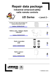
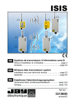
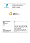
Industrial radio UC Series
remote controls
Typical applications :
Industrial lifting
Standard travelling cranes
Standard gantry cranes
Construction equipment
Tower cranes
1- Description
CONTENTS
Para.
A radio remote control provides numerous advantages:
Large freedom of movement
Easy to use
Precise, quality manoeuvres
Visibility
Productivity
With the UC radio remote controls, Jay Electronique provides solutions to the
broad range of standard industrial lifting applications.
Besides, a special attention has been given to ensure operator comfort through
the following features:
1 Description...................................1
2 Product features ..........................2
3 Dimensions ..................................3
4 Safety aspects and optional
functions ......................................4
5 Technical characteristics..............4
6 Radio frequencies........................6
7 Selection guide ............................6
Ergonomic transmitter enabling one-hand control
Control button accessibility
Button touch sensitivity
Compliance with European directives:
- Machines
Identification of functions controlled
Emergency stop Performance Level
Light-weight transmitter
PL d per EN ISO 13849-1 (Cat.3 per
Transmitter endurance, and fast, easy to replace plug-in battery pack
EN 954-1)
Adaptability to all radio configurations of the environment by possibility for
- Hertzian equipment and
changing frequency by a trained operator.
telecommunication terminals
Mechanical protection of function buttons to avoid any unintentional action
(low voltage, EM compatibility,
Transmitter carrying strap which hooks onto belt when unit is idle, or removable
radiofrequency spectrum)
shoulder strap (optional accessories)
ART conformity certificate
To further enhance safety when using this equipment, technical solutions and
innovative options are also proposed:
Page
Access is enabled by insertion of an electronic key in transmitter housing
Memorisation of use of remote control by recording number of operations
and durations for each movement (option)
Compliance with applicatives
standards :
- EN15011 (travelling cranes)
- EN13557 (lifting machines with
suspended load)
The receiver is also very easy to install:
Compact receiver
Spring-type connection terminals
Easy maintenance:
Customization entirely stored in electronic key
Diagnostic aid indicator lights
Fast repair by insertion of electronic key in an auxiliary transmitter
Parameter definition software (option)
électronique
E770 i - 0614
revision 01
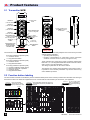
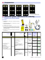
2- Product features
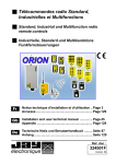
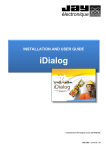
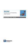
2.1 Transmitter UCE
Row No.4
(2 function buttons)
n°7
n°8
Row No.3
(2 function buttons)
n°5
n°6
Row No.2
(2 function buttons)
n°3
n°4
Row No.1
(2 function buttons)
n°1
Function button
labels
Green indicator light
«ON» and diagnostic
n°2
Red indicator light
«battery charge
level and diagnostic»
n°3
n°4
n°1
n°2
Insertion of battery pack
(ref: UWB) in the back
of transmitter
Location of
electronic key
Carrying strap hook
for belt fastening
clip or removable
shoulder strap
Stop palmswitch
button
8+2 button
housing model
6+2 button
housing model
The transmitter comes in 3 versions :
or
n°6
Yellow
electronic
key
«On/Horn»
button
or
n°5
Two parameters can be easily adapted to the environment by a trained
operator with the transmitter :
• Operating radio frequency
• Duration of temporization for «dead man» function (Automatic
shutdown of remote control in case of prolonged non use)
6 two-step pushbuttons (double speed)
+ 1 «On/Horn» button
+ 1 stop palmswitch button
8 two-step pushbuttons (double speed)
+ 1 «On/Horn» button
+ 1 stop palmswitch button
These operations are performed by simple procedures implementing
buttons nb.1, 2, 3, the stop palmswitch button and the «On/Horn» button,
with no need to open the transmitter or receiver.
The change of parameter can be however locked.
6 two-step pushbuttons (double speed)
+ 1 one-step pushbutton (single speed)
+ 1 electronic switch with 3 positions
+ 1 «On/Horn» button
+ 1 stop palmswitch button
The electronic key contains all the parameters of the remote control, it
is possible to use an auxiliary transmitter only with the electronic key
and a validation procedure.
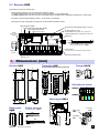
2.2 Function button labeling
The various button functions are identified by means of adhesive labels placed in the recesses provided in the transmitter unit housing at
each button location. The labels are supplied in the form of sheets with the various labels you will need for your application.
S
O
U
T
H
N
O
R
T
H
W
E
S
T
E
A
S
T
R
P
M
+
R
P
M
S
U
D
N
O
R
D
O
U
E
S
T
E
S
T
OFF
1 2 3 4 5 6
3
1
3+4
4
3+4
3 4
1
3 4
3 2
1
1+2
2
2
7 8 9
1
2
GATE
1+2
button
No.3 No.5 No.1 No.2 No.6 No.4
ON
3
L
E
F
T
6,4 mm
Kit of 48 white blank
labels, «customization» +
48 transparent protecting
labels.
6,4 mm
S
H
U
N
T
U
P
3
Standard label advised
buttons No.1 to No.6
R
I
G
H
T
D
O
W
N
4
green
blue
yellow
(Right) (Backward) (Forward)
F
O
R
W
A
R
D
2
brown
(Left)
R
E
V
E
R
S
E
Reference:
UWE205
22 mm
white
(Up)
Kit of 90 b/w labels «movements, special and
customization functions» for pushbuttons and
switches
22 mm
22 mm
black
(Down)
*
1
6,4 mm
Reference:
UWE207
1
Kit of 6 colored labels,
«movements», for double
speed pushbuttons (2 steps)
2
Reference:
UWE202
* = Label sheets provided as standard supply with UCE transmitter
2
UC Series - E770 i-0614 revision01
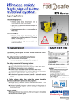
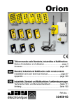
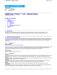
2.3 Receiver UCR
The receiver comes in 8 versions with :
- A basic board comprising 9 or 12 control relays following version.
+ 1 «Horn» relay (active when the «On/Horn» button is pressed, not auto-maintained)
+ 2 safety relays (active when the «On/Horn» transmitter button is pressed, auto-maintained until passive or active stop)
- Two types of power supply following version : 48-115 VAC or 48-230 VAC
- Three types of relay configuration according to the associated transmitter version
Cover
«Power supply»
passage
Safety relay RS1 and RS2
Safety relays terminal strips RS1 and RS2
Power supply terminal strips
Fuses «Power supply»
Connector for serial link board (DialogUC software)
V1 : Green LED «Power ON»
V2 : Red LED «Wrong identity code + diagnostic»
V3 : Green LED «Radio link established + diagnostic»
7 6 5 4 3 2 1
RS1 RS2
V1
V2
V3
Radio tuner
F1
F2
Fixed antenna (possibility of using a BNC
plug-in antenna with kit ref.: OWR01)
RK
R1
R2
R3
R4
R5
R6
R7
R8
R9
R10
R11
R12
Control relays
(R1 to R9 or R1 to R12 following receiver version)
Cable gland
«Control»
8 9 10 11 12 13 14 15 16 17 18 19 20 21 22 23 24 25 26 27 28 29 30 31 32 33
Control relay terminal strips
RK relay «Horn» terminal strips
RK relay «Horn»
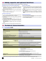
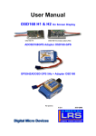
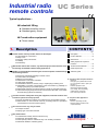
3- Dimensions (mm)
Receiver UCR
Transmitter UCE
100
(6+2 and 8+2 button housing versions)
120
66
27
70
Charger UCCU
40
53
60
170
28
110-230VAC / 5VDC, EU, UK and US plugs
4 x Ø4
245
220
Self-adhesive arrows
490
UWE003
229
170
180
490
UWE002
180
90
Wall support UDC1
35
30
48
35
Battery pack
UWB
40
Plug-in antennas
96
blue
yellow
22
Ø4
Battery pack
UWB
210
VUB084 1/4~
green
56
(for use with kit Ref. : OWR01)
23
brown
121
47
200
mini.
To charger
UCCU
Transmitter
UCE
335
VUB086 1/2~
UC Series - E770 i-0614 revision01
3
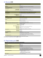
4- Safety aspects and optional functions
The UC remote controls implement numerous safety features, in particular :
Transmitter/receiver communication safety features :
Receiver safety feature :
Permanent radio link : by its non-directional design and
insensitivity to the presence of obstacles, the operator is
protected from exposure to handling risks during precision
manoeuvres and movements.
Each transmitter-receiver pair has its own specific identity
code
Hamming distance (minimum number of bits that differ
between 2 different messages) of 4.
Emergency stop Performance Level PL d per EN ISO 138491 (Cat.3 per EN 954-1) is ensured by redundant control of
the emergency stop circuit and use of guided contact safety
relays.
A passive shutdown device shuts down the system if the radio
link is jammed.
An electric interlocking for contradictory commands
(between buttons No.1 and No.2, No.3 and No.4, No.5 and
No.6).
Transmitter safety feature :
An active priority general shutdown command is generated
when the «stop palmswitch button» is pressed.
An electronic key limits access to the system to authorised
persons only.
An indicator light indicates an alarm in the event of an
insufficiently charged battery.
A «Standby» function shuts down the transmitter after a preprogrammed time period (1 to 98 mn) when no controls have
been generated.
This function can be disabled at any time to meet specific
needs.
Buttons protected mechanically against unintentional actions.
Functional safety feature :
Start-up sequences are implemented to ensure safe operation
by a trained, experienced operator.
55 ms response time compatible with the movement speeds
of the controlled equipment.
5- Technical characteristics
5.1 Transmitter UCE
Mechanical and environment withstand characteristics
Housing
ABS Choc, yellow, with mechanical button protection
IP65
Weight (with battery pack)
"6+2 buttons" housing model : 380 g
"8+2 buttons" housing model : 450 g
Dimensions
"6+2 buttons" housing model: 70x53x220 mm
"8+2 buttons" housing model : 70x53x245 mm
Operating temperature range
Storage temperature range (without battery pack)
Storage temperature range (with battery pack)
Attachment when idle
-20°C to +50°C
-30°C to +70°C
-20°C to +35°C
Wall-mounted (by fastening hook) or on belt (by fastening clip)
Electrical and radio characteristics
Power supply
Autonomy
Plug-in NiMH battery (battery pack, ref : UWB)
433-434Mhz bands : 24 hours / 50 % transmit time / buttons typical average use
869MHz band : 20 hours / 50 % transmit time / buttons typical average use
UHF
Radio transmission type
64 user programmable fre quencies in 433-434 MHz bands (see frequency list page 6)
Radio frequency
12 user programmable frequencies in 869 MHz band (see frequency list page 6)
<10 mW (license not required) fixed antenna
Transmission power
FM
Modulation
100 m in typical industrial environment / 300m in unobstructed area
Average range with fixed antenna (1)
Functional characteristics
Functions
"Standby" function
Indications
All versions comprise :
- 6 two-step pushbuttons (double speed)
- 1 "On/Horn" pushbutton
- 1 active priority emergency stop palmswitch button
- 1 electronic key lock
Additional functions for "8+2 buttons" housing model versions:
- 2 two-step pushbuttons (double speed)
or
- 1 one-step pushbutton (single speed) + 1 electronic switch with 3 positions
Time is user-programmable (01 to 98 mn or infinite)
- 1 red indicator light : "battery level" and "diagnostic"
- 1 green indicator light : "On" and "diagnostic"
(1) = Range will vary according to environment conditions of transmitter and reception antenna position (metal frameworks, walls … ).
4
UC Series - E770 i-0614 revision01
5.2 Receiver UCR
Mechanical and environment withstand characteristics
ABS, grey
IP65
1,2 kg (approx.)
120x240x100 mm (without antenna and without cable gland)
-20°C to +50°C
-30°C to +70°C
Housing
Weight
Dimensions
Operating temperature range
Storage temperature range
Cable lead-out
Power supply : 1 M16 cover (for cable diameter Ø 5 to 7 mm) (1)
Control outputs : 1 M32 plastic cable gland (for cable diameter Ø 20 à 26 mm)
Spring-type terminal strips for 0.08² to 2.5² section wires
Connection
Radio characteristics (complying with ETS 300 220)
64 programmable frequencies in 433-434MHz bands (see list on page 6)
12 programmable frequencies in 869 MHz band (see list on page 6)
Radio frequencies
Fixed antenna (2)
433-434Mhz bands : 1/4 wave
869MHz band : 1/2 wave
Better than -100dBm
Sensitivity
Electrical characteristics
48 VAC, -15% to +10%: 550 mA
115 VAC, -15% to +10%: 200 mA
230 VAC, -15% to +10%: 70 mA
Power supply and consumption
(with 2 safety relays + "horn" relay
and 5 functions relays pulled in)
Control
9 relays + 1 "Horn" relay
or
12 relays + 1 "Horn" relay
Safety
Number of output relays simultaneously controllable
Outputs
Category :
2 relays with linked and guided contacts
8 (including "RS1-RS2" safety relays and the "horn" relay)
Independent 1 NO relay
DC13 0,5A / 24VDC
AC15 2A / 230VAC
2000VA
8A (control relays and "Horn" relay), 6A ("Safety" relay)
10 mA (12 Vmin.), 100 mA recommended
250VAC
Max. breaking capacity :
Max. current :
Min. current :
Max. voltage :
Service life : under 230VAC, 70VA, cosphi=0,75 : 3x10 6 cycles
Response time
Active shutdown time
Passive shutdown time
Indications
On start-up : 0,5 s max.
On control : 0,07 s max.
0,16 s max.
1,15 s max.
1 green indicator light: "Power supply ON"
1 red indicator light: "wrong identity code" and "diagnostic"
1 green indicator light: "radio link established" and "diagnostic"
Power supply protection
Against overcurrent by fuse
(1) = The cover can be replaced by a M16 plastic cable gland to be mounted at the same place.
(2) = possibility to use plug-in antenna with ref.: OWR01 accessory.
5.3 Plug-in battery pack UWB
Mechanical, functional and environmental characteristics
Housing
ABS, black
IP40
Dimensions
40x96x23 mm
Storage temperature range
-20°C to +35°C
Fast charging time temperature range
0°C to +35°C
Complete charging time
7 hours if battery pack is completely discharged
Partial load time (at +20°C)
10 mn of charge get approximately 1 hour of autonomy
1 hour of charge gets approximately 8 hours of autonomy
6 hours of charge get approximately 12 hours of autonomy
Indications (Charge status)
1 indicator light on battery pack (charging):
Orange = fast charge
Green = slow charge and up-keep charge
1 red indicator light on transmitter (low battery)
Charge voltage
UC Series - E770 i-0614 revision01
5 VDC (by UCCU charger)
5
6- Frequencies
433-434 MHz bands
Channel Frequency
nb.
MHz
433,100
01
433,125
02
433,150
03
433,175
04
433,200
05
433,225
06
433,250
07
433,275
08
433,300
09
433,325
10
433,350
11
433,375
12
433,400
13
433,425
14
433,450
15
433,475
16
869 MHz band
Channel Frequency
nb.
MHz
433,500
17
433,525
18
433,550
19
433,575 (1)
20
433,600
21
433,625 (1)
22
433,650
23
433,675 (1)
24
433,700
25
433,725 (1)
26
433,750
27
433,775 (1)
28
433,800 (2)
29
433,825 (1) (2)
30
433,850 (2)
31
433,875 (1) (2)
32
Channel Frequency
nb.
MHz
433,900 (2)
33
433,925 (1) (2)
34
433,950 (2)
35
433,975 (1) (2)
36
434,000 (2)
37
434,025 (1) (2)
38
434,050 (2)
39
434,075 (2)
40
434,100 (2)
41
434,125 (2)
42
434,150 (2)
43
434,175 (2)
44
434,200 (2)
45
434,225 (2)
46
434,250 (2)
47
434,275 (2)
48
Channel Frequency
nb.
MHz
434,300 (2)
49
434,325 (2)
50
434,350 (2)
51
434,375 (2)
52
434,400 (2)
53
434,425 (2)
54
434,450 (2)
55
434,475 (2)
56
434,500 (2)
57
434,525 (2)
58
434,550 (2)
59
434,575 (2)
60
434,600 (2)
61
434,625 (2)
62
434,650 (2)
63
434,675 (2)
64
Channel Frequency
nb.
MHz
869,9875
01
869,9625
02
869,9375
03
869,9125
04
869,8875
05
869,8625
06
869,8375
07
869,8125
08
869,7875
09
869,7625
10
869,7375
11
869,7125
12
Adjacent intervals : 0,025 MHz
(1) = List of frequencies available for Denmark
(2) = List of frequencies available for Singapore
7- Selection guide, references for ordering
7.1 Standard sets selection guide
A set includes :
1 transmitter with a battery pack + transmitter accessories
listed above
1 receiver with fixed antenna + 1 electronic key + receiver
accessories listed above
1 Installation and user manual
1 pre-wired cable on industrial male connector side. The other
side comes with nude identified wires; they are to be wired into
the receiver according to the wiring diagram corresponding
to the travelling crane.
As an option : 1 Lamp-Horn kit for travelling crane to be wired
into the receiver.
Transmitter
Transmitter configuration
2m cable
equipped with a
male industrial
connector
Receiver
Transmitter
reference
Receiver configuration
Receiver
reference
6 two-step pushbuttons (double speed)
+ 1 "On/Horn" pushbutton
+ 1 stop palmswitch button
433-434MHz band
1 battery pack included
2 protective foams (mounted)
1 kit with 6 colored labels for "movements"
Delivered with following accessories :
1 2nd battery pack (ref. : UWB)
+ 1 label kit (ref. : UWE202)
+ 1 Wall support for battery pack (ref. : UDC1)
+ 1 charger for battery charging (ref. :UCCU)
Standard set
reference
Without option
UCPS6A
With option
UCPS6C
Without option
UCPS6E
With option
UCPS6F
Without option
UCPS6B
With option
UCPS6D
UDWR14
UCR0AM0
Delivered with following accessories :
1 "4 Self-adhesive directional colored arrows on
travelling cranes" (ref. : UWE002)
+ 1 fastening Kit by magnetic contacts (ref. :
UDWR38)
Cable with 24-pin
connector ref :
UDWR13
UCE222200
12 + 3 relays (With dedicated 2nd speed relay
for two-step pushbuttons)
Power supply : 48-230 VAC
433-434MHz band
1 electronic key
Delivered with following accessories :
1 "4 Self-adhesive directional colored arrows on
travelling cranes" (ref. : UWE002)
+ 1 fastening Kit by magnetic contacts (ref. :
UDWR38)
6
With or Without
Cable with 16-pin
connector ref :
9 + 3 relays (With common 2nd speed relay for
two-step pushbuttons)
Power supply : 48-230 VAC
433-434MHz band
1 electronic key
Connection cable
reference
Option "Lamp-Horn
kit for travelling
crane + fastening
by 2 magnetic
Standard sets
contacts + 2m
cable" ref:
UCWR38
UCR0BM0
Cable with 24-pin
connector ref :
UDWR13
UC Series - E770 i-0614 revision01
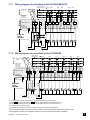
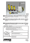
7.1.1 Wiring diagram for standard units UCPS6A/6E/6C/6F
Buttons numbers
No.1
Button positions
U
C
E
U
C
R
UCE transmitter
buttons
On Horn
STOP
No.2
No.3
No.4
No.5
No.6
NEUTRAL
Step No.1
(speed No.1)
Step No.2
(speed No.2)
UCE transmitter
button action
on the UCR
receiver relays
RS1 RS2
UCR receiver relays
R1
RK
R2
R3
R4
R5
R6
R7
R8
R9
Connection
terminal number
on UCR receiver
3 2
1
(*)
UCR
power supply F
5
4
7
6
8
10 11
12 13
14 15
16 17
18
19
20
21
22 23
24 25
26 27
U0
0
External
wiring
example
External driven loads
K1
K1
K1
K2
K2
K2
(**)
(**)
**
(**)
*
L1
U1
9
F1
LA
UA
N1
FA
NA
7.1.2 Wiring diagram for standard units UCPS6B/6D
Buttons numbers
No.1
Button positions
U
C
E
U
C
R
On Horn
STOP
UCE transmitter
buttons
No.2
No.3
No.4
No.5
No.6
NEUTRAL
Step No.1
(speed No.1)
Step No.2
(speed No.2)
UCE transmitter
button action
on the UCR
receiver relays
RS1 RS2
UCR receiver relays
R1
RK
R2
R3
R4
R5
R6
R7
R8
R9
R10
R11
R12
Connection
terminal number
on UCR receiver
3 2
(*)
UCR
power supply F0
1
5
4
6
8
9
10 11
12 13
14 15
16 17
18
19
20
21
22 23
24 25
26 27
28 29
30 31
32 33
U0
External
wiring
example
External driven loads
K1
(**)
(**)
*
L1
U1
7
K1
K1
K2
K2
K2
(**)
**
F1
N1
LA
UA
FA
NA
(*)= The power supply connection depends on the type of receiver and the power supply required.
(terminals 2 - 1 for power supply 48VAC or 3 - 1 for power supplies 230VAC or 115VAC following versions)
(**)= Relay life is increased by the use of surge limiters (ex: RC network for AC, Zener + diodes for DC etc...)
(**)= K1 and K2 must have guided contacts
*
(**)= Elements wich indicate start of remote controlled machines (ex: horn, rotating / flashing light etc...)
**
"Safety" relay RS1 and RS2 are switched "on" by the "On/Horn" transmitter pushbutton, and is held in position until the
stop palmswitch is pressed (active shutdown) or until the loss of the radio transmission (passive shutdown).
UC Series - E770 i-0614 revision01
7
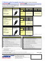
7.2 Selection guide for separate elements (transmitter / receiver / accessories)
Transmitter UCE
Receiver UCR
Transmitters are delivered with a single battery pack (a second
can be ordered separately with the reference: UWB) and without
electronic key, this one being delivered with the receiver (or can be
ordered separately with the reference UCWE22X).
Button configuration description
Receivers are delivered with an electronic key programmed according to the
number of receiver relays and to the transmitter model.
Transmitter reference
UCE22220 (433MHz)
UCEC2220 (869MHz)
Transmitter UCE with:
6 two-step pushbuttons (double speed).
+ 1 "On/Horn" button
+ 1 stop palmswitch button
433 MHz
869 MHz
Relay configuration
description
Transmitter reference
UCE2222D0 (433MHz)
UCEC222D0 (869MHz)
Transmitter UCE with:
6 two-step pushbuttons (double speed)
+ 1 one-step pushbutton (single speed)
+ 1 electronic switch with 3 positions
+ 1 "On/Horn" button
+ 1 stop palmswitch button
relays
9+3
48 - 230 VAC
(1)
relays
48 - 115 VAC
48 - 230 VAC
UCR0BL0 UCR0BM0
UCRABL0 UCRABM0
UCR0AL0 UCR0AM0
UCRAAL0 UCRAAM0
With dedicated second speed relay
for two-step pushbuttons
With common second speed relay
for two-step pushbuttons
Number of relays
48 - 115 VAC
Power supply
433 MHz
Receiver
reference
12+3 (1) relays
869 MHz
48 - 230 VAC
UCR0BL1 UCR0BM1
UCRABL1 UCRABM1
With common second speed relay
for two-step pushbuttons
Relay configuration
description
delivered with:
1 battery pack (ref.UWB)
+ 1 label kit (ref.UWE207)
Button configuration description
(1)
48 - 115 VAC
Power supply
Receiver
reference
12+3
delivered with:
1 battery pack (ref.UWB)
+ 1 label kit (ref.UWE207)
Button configuration description
Number of relays
Transmitter reference
Transmitter UCE with:
8 two-step pushbuttons (double speed)
+ 1 "On/Horn" button
+ 1 stop palmswitch button
UCE222220 (433MHz)
UCEC22220 (869MHz)
delivered with:
1 battery pack (ref.UWB)
+ 1 label kit (réf.UWE207)
Number of relays
12+3
48 - 115 VAC
Power supply
Receiver
reference
+ 1 relay for the one-step
pushbutton
+ 2 relays (1/1+2/2) for the
electronic switch with 3 positions
433 MHz
869 MHz
Relay configuration
description
(1)
relays
48 - 230 VAC
UCR0BL2 UCR0BM2
UCRABL2 UCRABM2
With common second speed relay
for two-step pushbuttons
(1)= 2 safety relays + 1 «Horn» relay
Accessories for UCR receiver
Reference
Description
Reference
Description
UCCU
Charger 110-230VAC/5VC (EU, UK and US plugs) (for UWB battery pack charging)
OWR01
BNC tuner connector for BNC plug-in antenna (4)
UWB
Plug-in battery pack (2)
VUB084
1/4 wave straight antenna, BNC plug, for 433-434MHz bands (5)
UDC1
Wall support for stowing when idle and battery pack in charge
VUB086
1/2 wave straight antenna, BNC plug, for 869MHz band (5)
UCWE22X Programmed electronic key (parameters to be supplied) (2) (3)
VUB060
90° BNC elbow for VUB084 antenna or BNC antenna extension (5) (6)
UDP1
Belt fastening clip
VUB105
2 m extension for BNC antenna + mounting bracket (5)
UWE102
Removable shoulder strap
VUB125
5 m extension for BNC antenna + mounting bracket (5)
UWE301
Protective case for transmitter "6+2 button" version
VUB131
10 m extension for BNC antenna + mounting bracket (5)
UWE302
Protective case for transmitter "8+2 button" version
UWE002
4 Self-adhesive directional colored arrows on travelling cranes
UWE313
Protective sleeve for transmitter "6+2 button" and "8+2 button" version
UWE003
4 Self-adhesive directional black/white arrows on travelling cranes
UWE201
Kit of 6 white/black labels, «movements», for double speed pushbuttons (2 steps)
UDWR12
Common wiring accessory
UWE202
Kit of 6 colored labels, «movements», for double speed pushbuttons (2 steps)
UDWR13
24-pin plug-in connector + 2 m cable
UWE205
Kit of 48 white blank labels, "customization"
UDWR14
16-pin plug-in connector + 2m cable
UWE207
Kit of 90 b/w labels "movements, special functions and customization" for pushbuttons
and switches (2)
UDWR38
Fastening Kit for receivers by 4 magnetic contacts
UCWR32
Serial link board for "DialogUC" PC Software
UCWR36
"DialogUC" PC Software (CD-ROM + cable PC/UCR) (7)
(2) = 1 accessory supplied with product
(3) = A programmed electronic key is delivered with the receiver, it is however possible to order an electronic key by supplying us the following 2 parameters :
- the receiver identity code,
- the transmitter reference.
(4) = BNC antenna and BNC extension to be ordered separately.
(5) = Require BNC tuner connector kit ref.: OWR01
(6) = Not suitable for direct connection to antenna ref.: VUB086, in this case, use an intermediate extension type VUB1••.
(7) = Require serial link board ref.: UCWR32
The products presented in this document are subject to change. Product descriptions and characteristics are not contractually binding.
Please go to our internet site www.jay-electronique.com to download the most recent updates to our documentation.
E770 i - 0614
revision 01
Distributor
électronique
ZAC la Bâtie, rue Champrond
F38334 SAINT ISMIER cedex
+33 (0)4 76 41 44 00 - +33 (0)4 76 41 44 44
www.jay-electronique.com
11.07.2014 - d.B rev01 - E.D.
Accessories for UCE transmitter