1
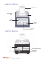
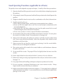
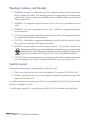
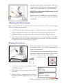
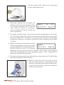
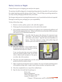
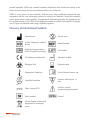
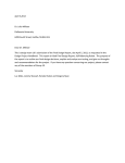
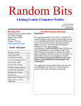
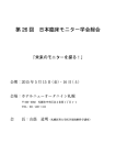
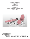
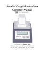
Sonoclot® Coagulation Analyzer
Operator’s Manual
SC1 Revision 2.1
Manufactured for: Sienco, Inc.
7985 Vance Drive, Suite 104 Arvada, CO 80003 USA
303-420-1148 1-800-432-1624 Fax 303-379-4403
www.sienco.com e-mail: [email protected]
Copyright © 1999-2009 Sienco®, Inc. All Rights Reserved.
Manufactured For: Sienco®, Inc.
7985 Vance Drive, Suite 104 Arvada, CO 80003 USA
303/ 420-1148 303/ 379-4403 (FAX) • [email protected] (e-mail)
http://www.sienco.com
Sonoclot is a registered trademark of Sienco®, Inc.
Sonoclot Analyzers are protected under U.S. and foreign patents.
QNET BV
Hommerterweg 286
6436 AM Amstenrade
The Netherlands
Table of Contents
Chapter 1: Installation and Setup
1-1
Principle of Operation and Intended Use
1-1
Head Assembly
1-1
Model SC1 - Front View
1-2
Model SC1 - Back View
1-2
Package Contents
1-3
Installation1-3
Good Operating Procedures (applicable for all tests)
1-5
Warnings, Cautions, and Hazards
1-6
Quality Control
1-6
Chapter 2: Running a Whole Blood Sample
Analyzer Preparation
Cuvette and Probe Setup
Obtaining the Blood Sample
Running the Analyzer
2-1
2-1
2-2
2-3
2-3
Chapter 3: Maintenance and Troubleshooting
3-1
Maintenance3-1
Troubleshooting3-2
Warning and Error Messages
3-2
Factory Service or Repair
3-3
AppendixA-1
ReferencesA-1
WarrantyA-2
Technical Specifications
A-2
Environmental Conditions for Transportation and Storage
A-2
Environmental Conditions for Use
A-3
Electrical Classification
A-3
Disposal Instructions
A-3
Glossary of International Symbols
A-4
Decontamination Form
A-5
Chapter 1:
Installation and Setup
Principle of Operation and Intended Use
The Sonoclot Coagulation Analyzer calculates onset of clot formation and clot rate for in vitro
coagulation studies by monitoring mechanical changes that occur in blood samples during
hemostasis. The mechanism is a tubular probe that moves up and down within a blood sample.
As the sample progresses through various stages of clotting, the electronic circuitry detects
increasing resistance. This produces a series of electronic signals that are processed by a
microcomputer. Results are reported on the LCD display panel.
Head Assembly
analyzer head
probe mount hub
convenience wells
cuvette
holder
platen
head alignment pin
1-1
Model SC1 - Front View
analyzer head
convenience
well
platen
LCD
display
Start/Stop
button
Select Test
button
Model SC1 - Back View
serial number
label
USB port
1-2
Chapter 1: Installation and Setup
electrical information
power cord
receptacle
Package Contents
•Sonoclot Coagulation Analyzer (Model SC1)
•power adaptor and cord
•probe extractor
•operator’s manual
•USB cord
•SonoView installation CD
Installation
1) Unpack the contents of the shipping container and check you have all the above
items.
NOTE: Sienco recommends that you retain the original shipping box in case you need
to return your instrument for service.
2) Pull the ribbon to remove the packaging from the
top of the instrument. Then pull the ribbon to lift the
instrument out of the packaging foam in the bottom
of the box.
3) Remove the analyzer from the plastic bag.
4) Carefully remove the tape from the top and back of
the instrument.
5) Remove the spacer tabs from between the analyzer
case and the head assembly platen. Keep these tabs
with the original packaging.
6) Plug the power cord into the analyzer and an easily accessible grounded wall outlet.
Do not use an ungrounded extension cord or adaptor. Do not obstruct access to the
outlet.
7) The analyzer will automatically turn on. First, the LCD display will illuminate. Next,
the analyzer will display the version number, product name, and copyright.
8) The analyzer will begin warming. While
warming, the display reads:
g bAC T
H eati n g
˚
36.3
9) When the analyzer has reached 37.0ºC, the display indicates the default test. The
analyzer is now ready to run a test.
10) Review the remainder of this chapter.
Chapter 1: Installation and Setup
1-3
Installing & Using SonoView Data Management Software (SonoView)
The analyzer indicates real time results on the LCD display. It also collects and stores data much
like a digital camera. This data can be accessed by connecting the analyzer to a computer
running SonoView.
To install SonoView on your computer:
1) Read the installation instructions and hardware specifications on the CD sleeve.
Instructions are also located in PDF format on the CD.
2) Plug a USB cord into the back of the analyzer and a USB port on your computer.
NOTE: The analyzer requires a 1.1 USB Port or higher.
3) Open SonoView on your computer. For software instructions, please see the SonoView
operator’s manual PDF file on the installation disk.
1-4
Chapter 1: Installation and Setup
Good Operating Procedures (applicable for all tests)
The quality of test results depends on proper technique. Carefully follow these precautions:
1) Operator should read this operator’s manual in its entirely before attempting to operate
the analyzer.
2) Only properly trained lab personnel and healthcare professionals should operate the
analyzer.
3) Diagnosis should be based on test results in combination with clinical observations.
4) Handle materials with care:
•When taking a blood sample, avoid heparin contamination from catheters.
•Never use the first sample from a new line to avoid sample contamination with
tissue thromboplastin.
•Keep blood, dirt, and other substances away from the probe mount hub to avoid
contaminating the electromechanical transducer.
•Never reuse a probe or cuvette to prevent thrombin contamination.
5) For consistent results, the cuvettes should be warmed prior to analysis. To warm, place
the cuvette in its holder at least 30 seconds prior to running a test.
6) Always insert and remove the probe by moving it vertically over the probe mount
hub. Never move the hub horizontally. Make sure the probe is fully seated to avoid
interference with the stir-bar.
7) Always remove the cap from the cuvette prior to placing it into the cuvette holder.
Failure to do so can damage the transducer.
8) The cuvette must be fully seated in the cuvette holder to avoid interference between
the probe and stir-bar.
9) Do not overfill the cuvette. The proper fill level is slightly below the inner rim of the
cuvette.
10) Native whole blood must be analyzed within 2 minutes or less of collection.
11) Perform QC testing to verify proper operation of the analyzer and activation cuvettes.
See page 1-6.
12) Use proper biohazard handling techniques to dispose of probes and cuvettes.
13) On rare occasions, mechanical disturbances may cause incorrect results. Always
inspect results to ensure that they are consistent.
14) High viscosity blood samples (immersion response > 25 clot signal units as displayed
on the instrument) can stratify. Use an external device to mix the blood sample before
placing it in the cuvette.
Chapter 1: Installation and Setup
1-5
Warnings, Cautions, and Hazards
1) WARNING: As with any laboratory test result, diagnosis should not be based solely
on the analyzer test results. The attending physician is responsible for interpreting the
analyzer test results in conjunction with the patient’s condition, other test results, and
clinical observations.
2) WARNING: To safeguard against electrical shock, only use a grounded electrical
outlet.
3) WARNING: Use only as specified by Sienco, Inc. Otherwise, equipment protection
may be impaired.
4) CAUTION: Only properly trained laboratory personnel and/or other appropriate health
care professionals should use the analyzer.
5) CAUTION: A biomedical engineering department should check the analyzer at least
once a year for compliance with leakage standards.
6) HAZARD: Human blood is a biohazardous material. The operator should wear
appropriate protective gear when handling blood and/or test cuvettes containing
blood samples. Biocontaminated materials should be handled and disposed of
properly in accordance with hospital, local, state, and federal regulations.
7) CAUTION: Do not place the analyzer on counter tops where other vibrating instruments,
such as centrifuges, are located. Mechanical vibration may cause erratic results.
Quality Control
Proper performance requires regular quality control (QC) tests:
1) Daily, run a reference viscosity test for the analyzer. This requires QC kit 900-1303.
2) Monthly, and prior to the use of a new shipment, validate the activated cuvettes. This
requires QC kit 900-1318.
Complete instructions for running each QC test are included in the kits. The kits also include
forms for recording QC results.
To order quality control kits, contact Sienco at 800-432-1624 or contact your distributor.
1-6
Chapter 1: Installation and Setup
Chapter 2:
Running a Whole Blood Sample
The analyzer monitors mechanical changes that occur during hemostasis. This section describes
how to prepare and run a test with native whole blood samples. Use only test kits available
from Sienco, Inc. Sienco offers different tests for different applications. Choose the test best
suited for your application.
Analyzer Preparation
1) Cuvettes should be placed in the convenience wells
so they will be ready when the blood is drawn. Place
probes into the lids of the cuvettes.
probe
cuvette
2) If the analyzer has just been recently turned on, allow it to warm, with head assembly in
the down position, until the analyzer reaches 37°C. If the analyzer is not at the desired
temperature it will display an error message and not run the test.
3) When the analyzer is ready the display reads:
NOTE: Results from the previous test may be
displayed on the bottom of the LCD display.
g bAC T
4) Press the “Select Test” button on the front panel until the desired test is displayed on
the LCD.
2-1
Cuvette and Probe Setup
1) Open the head by tilting it backwards. The display
will read “Open.”
2) Sharply tap the cuvette on a hard surface to dislodge activation powder from the sides
and lid.
3) With a slight twisting motion, use the cuvette to seat
the probe on the mount hub. This motion should
result in the probe sliding straight over the probe
mount hub. The hub should not move sideways. The
probe must be fully seated for proper operation.
4) Remove the cuvette, leaving the probe on the hub.
5) Remove the lid from the cuvette by placing it in a
convenience well and popping the lid off with your
thumb.
2-2
Chapter 2: Running a Whole Blood Sample
6) Insert the cuvette into the cuvette holder. Make sure
it is fully seated. Close the head. Allow the cuvette to
warm in the cuvette holder for at least 30 seconds.
DO NOT close the head on a lidded cuvette. It will
damage the instrument.
Different tests have different set-up requirements.
Please refer to the product insert for detailed
instructions.
Obtaining the Blood Sample
Native whole blood must be analyzed within 2 minutes of collection. When drawing blood,
observe the following precautions:
1) Carefully decide where to draw the sample. Contamination (from a heparinized line, a
heparin-impregnated catheter, or a surgery prep line) will cause inaccurate results.
2) Withdraw blood in a smooth, slow, and non-traumatic manner. Do not use force.
3) When drawing from an anesthesia or pump port, use a 2-syringe technique. Discard the
first syringe of 2 to 3 ml. Use the second syringe for the sample. You MUST use plastic
syringes to avoid uncontrolled glass activation.
Running the Analyzer
1) Transfer the whole blood sample from the syringe into
the warmed cuvette. Use a blunt cannula tip for a
clean and controlled fill.
Fill the warmed cuvette with the blood sample until the
fluid level is slightly below the inner rim of the cuvette.
This volume is approximately 330 to 360 µl.
Fill slightly below here
2) Leaving the head open, immediately press the
START/STOP button.
3) The magnetic stirrer will rotate and the display
will read:
4) When mixing is completed, the analyzer
will beep and the display will read: “Close
Head.”
g bAC T
M i x i ng
g bAC T
C l o s e Head
Chapter 2: Running a Whole Blood Sample
2-3
5) Close the analyzer head. Make sure it is fully seated
over the head alignment pin.
6) During data collection, the LCD display will
show the test being run, the clot signal reading
(CS), the time in seconds, and “???” for each
result. When the analyzer is calculating a
result, the display will flash the number the
result is greater than.
g bAC T
13
11
AC T=???? CR=???
7) The sample is initially a liquid. After several minutes the sample begins to evolve into a
clot. The analyzer detects this initial clot formation and calculates the time the sample
remained a liquid (ACT). During the next several minutes of analysis, the fibrinogen
converts into a fibrin gel. The analyzer calculates the rate of change in the clot signal
(Clot Rate).
8) When a result has been calculated, the analyzer
g bAC T
will beep and display the time that the sample
remained a liquid (ACT) and the Clot Rate (CR),.
AC T= 177
CR= 19
Times for results vary from 2 to 20 minutes
depending on heparin levels and clinical conditions. The numeric result is displayed
next to the corresponding text for the appropriate channel. “NR” is displayed if no
results were found for the test sample.
9) The analyzer will automatically stop data collection when results for ACT and Clot Rate
have been calculated or after 30 minutes.
10) Open the head and remove the probe from the
hub with a probe extractor. Avoid moving the hub
sideways. Propery discard the probe and the cuvette.
Lower the head assebly to maintain temperature
control of the instrument.
2-4
Chapter 2: Running a Whole Blood Sample
Chapter 3:
Maintenance and Troubleshooting
Maintenance
Cleaning
Clean after use to reduce biohazard risks. The analyzer can be sprayed or wiped with a
disinfectant approved by your institution. Close the heads when spraying to avoid contaminating
the transducers. Avoid excess wetting. Place a clean probe on the probe adaptor to protect
the sensing mechanism while cleaning. Gently wipe around the cuvette holders or inside
the heads. Do not clean the probe mount hubs, unless absolutely necessary. The transducers
attached to the probe mount hubs can easily be damaged by debris or liquids.
NOTE: Do not use isopropyl alcohol or other solvents on the front panel or LCD cover.
Calibration & Service
The user cannot calibrate or service the analyzer. Running a reference viscosity QC test
(PN 900-1302) will verify if the analyzer is operating within calibration standards. Sienco
recommends performing the reference viscosity QC test daily, prior to use of the analyzer.
If the analyzer requires calibration or service, contact Sienco, Inc. or your distributor.
3-1
Troubleshooting
If you have a problem with the analyzer, follow these steps:
1) Review “Warnings, Cautions, and Hazards” on page 1-6.
2) Review “Good Operating Procedures” on page 1-5.
3) Review the operating instructions that come with the test you are running.
4) If problems persist, contact the Sienco service department:
Phone:
Toll Free:
Fax:
E-mail:
Mail:
303-420-1148
800-432-1624
303-379-4403
[email protected]
Sienco Service Department
7985 Vance Drive, Suite 104
Arvada, CO 80003 USA
Warning and Error Messages
The Sonoclot Analyzer will occasionally display messages that may not be familiar. Below are
some examples of these messages and procedures to follow, if necessary.
“NOISE” indicates that the clot signal is being disturbed by either mechanical noise, such as
bumping the analyzer, or by interference between the probe and the cuvette. Check to ensure
that the probe is tight against the mount hub and the cuvette is in contact with the bottom of
the cuvette holder. The message should disappear within a few seconds.
“ERROR” indicates that the self test routine has detected a problem. Normally, the message
will disappear after several seconds. You can resume testing then. If the error message remains,
make a note of the error number and call Sienco’s service department.
“TEST NOT RUN, NOT AT TEMP” indicates that the analyzer is not to temperature and the
test was not run. The analyzer must be at 37°C to run a test.
“NR” indicates that no results were found for the last test analysis. This can occur due to
operator error (i.e. failure to close instrument head within 60 seconds of “Close Head” message),
instrument error, or an unusual clot that cannot be analyzed.
NUMBERED ERROR CODES: The analyzer is programed to display various numbered error
codes. Should your analyzer display a numbered error code, record the number displayed
and contact your distributor or Sienco’s service department.
If you have any questions in regards to a display message, call Sienco’s service department at
800-432-1624 or 303-420-1148.
3-2
Chapter 3: Maintenance and Troubleshooting
Factory Service or Repair
Contact Sienco prior to shipping your analyzer for repairs.
The analyzer should be shipped in its original packing materials, if possible. If you do not have
the original packing materials please contact Sienco. We will ship you packing materials or
you may use the packaging materials from your loaner.
We charge a minimum fee for testing the instruments, even if you decide not to have it repaired.
Damages caused by poor packaging are your responsibility.
To ship, follow these steps:
1) Remove cuvettes, probes, power cord, and other supplies.
2) Photocopy the decontamination form at the end of this manual.
3) Clean and decontaminate the analyzer according to your institutional guidelines and
fill out the decontamination form. Failure to fill out form and include with the analyzer
will result in a $150 decontamination fee.
4) Carefully slide the spacer tabs between the instrument case
and platen. Tape the back of the platen and the top of the
instrument case as shown. Tape the instrument head down as
shown. Place the analyzer in a large, clean plastic bag and
fold the open end under the instrument.
5) Place the instrument in the molded foam in
the bottom of the box, with the ribbon running
underneath the analyzer as shown.
If you are also returning your power adaptor
and cord, fold the power cords, secure each
with a rubber band, and place in the spaces
on either side of the analyzer.
6) Place the top of the molded foam over the analyzer. Make sure the foam is securely
packed around the analyzer head.
7) Make sure the decontamination form is complete. Be sure to include a brief description
of the problem along with a contact name, phone number, and purchase order.
8) Place the completed form on top of the molded foam.
9) Tape the box shut and ship the package to:
Sienco, Inc.
Service Department
7985 Vance Drive, Suite 104
Arvada, CO 80003 USA
Chapter 3: Maintenance and Troubleshooting
3-3
Appendix
References
Sonoclot Analysis is used in many clinical and research applications and consequently is
referenced in numerous studies and articles. For a complete list of references, please visit our
web site at www.sienco.com.
1) Nilsson CU and Engström. Monitoring fondaprinux with the Sonoclot. Blood Coagulation
and Fibrinolysis. 2007; 18: 619-622.
2) Ganter MT, Monn A, Tavakoli R, et al. Monitoring activated clotting time for combined
heparin and aprotinin application: in vivo evaluation of a new aprotinin-insensitive test
using Sonoclot. Eur J Cardiothorac Surg. 2006; 30(2): 278-84.
3) Shibata T, Sasaki Y, Hattori K, et al. Sonoclot analysis in cardiac surgery in dialysis
dependent patients. Ann Thorac Surg. 2004; 77(1): 220-05.
4) Liszka-Hackzell JJ and Ekback G. Analysis of the information content in Sonoclot data
and reconstruction of coagulation test variables. Journal of Medical Systems. 2002;
26(1): 1-8.
5) Pivalizza EG, Pivalizza PJ, Kee S, Gottschalk LI, Szmuk P, Abramson DC. Sonoclot analysis
in healthy children. Anesth Analg. 2001; 92(4): 904-6.
6) Santucci RA, Erlich J, Labriola J, et al. Measurement of tissue factor activity in whole
blood. Thromb Haemost. 2000; 83(3): 445-54.
7) Ekback G, Carlsson O, Schott U. Sonoclot coagulation analysis: a study of test variability.
J Cardiothorac Vasc Anesth. 1999; 13(4): 393-7.
8) Hett DA, Walker D, Pilkington SN, Smith DC. Sonoclot analysis. Br J Anaesth. 1995;
75(6): 771-6.
9) Steer PL, Krantz HB. Thromboelastography and Sonoclot analysis in the healthy patient.
J. Clin Anesth. 1993; 5(5): 419-24.
10) Shenaq SA, Saleem A. Viscoelastic measurement of clot formation: the Sonoclot. In:
Ellison N, Jobes DR, eds. Effective Hemostasis in Cardiac Surgery. Philadelphia, PA:
Harcourt Brace Jovanovich, Inc.; 1988: 183-93.
11) Newland MC, Chapin JW, Hurlbert BJ, Kennedy EM, Newland JR. Thrombelastograph and
Sonoclot Signature monitoring of changes in blood coagulation following cardiopulmonary
bypass. Anesthesiology. 1987; 67(3A); A199.
12) Newlin, F., Ens, G., Leppke, L. and Hamstra, R.: “Heparin Control with the SONOCLOT”.
American Journal of Medical Technology, 44: 508, 1978.
A-1
Warranty
The Sonoclot Coagulation Analyzer has a 2-year warranty that it conforms to specifications and
is free of defects in material and workmanship. The warranty is limited to the replacement or
repair of defective parts and components. The warranty shall be voided if the product is:
1) Used in any manner or subjected to any condition that is inconsistent with its intended
purpose or accepted industry practice; or
2) Modified in any way without prior written approval by Sienco; or
3) Repaired in any manner so as to adversely affect its operation or reliability by persons
other than Sienco or its agents.
Warranty claims shall be submitted in writing to Sienco during the 2-year warranty period.
The claim shall state the nature and details of the analyzer defect and the serial number
of the analyzer. The claim must accompany any defective product submitted for repair or
replacement.
Purchasers must decontaminate and package the analyzer per instructions on pages 3-1 and
3-3. Such products shall, at Sienco’s election, be either repaired, replaced or returned.
Technical Specifications
Width
4.25”
10.8 cm
Depth
5.75”
14.6 cm
Height
4.75”
12.1 cm
Weight
2.5 lbs
1.13 kg
Electrical voltage requirement
100 to 240V
Electrical power requirement
9V
Frequency
50 to 60 Hz
Temperature regulation of platen
37°C ± 0.5°C
Viscosity range for test sample
<80 cP
, 2A
Environmental Conditions for Transportation and Storage
70°C
-25°C
Transport and store within the ambient temperature range of -25°C
and 70°C.
95%
Transport and store to a maximum relative ambient humidity of 95%.
A-2
Appendix
Environmental Conditions for Use
Indoor use only.
Use at a maximum altitude of 2000m.
27°C
Use within the ambient temperature range of 18°C and 27°C.
18°C
80% up to
31°C
50% at
40°C
Use at a maximum relative humidity of 80% for temperatures up to 31°C
decreasing linearly to 50% relative humidity at 40°C.
Mains supply voltage fluctuation shall not exceed ± 10%.
The unit is intended for INSTALLATION CATEGORY II.
Installation Category II: Local level, appliances, Portable equipment etc.,
with smaller transient overvoltages than Installation Category III.
The unit is intended for use in a POLLUTION DEGREE 2 ENVIRONMENT.
Pollution Degree 2 is nonconductive pollution of the sort where occasionally
a temporary conductivity caused by condensation must be expected. This
is the usual pollution degree used for equipment being evaluated to 60950
and is suitable for equipment employed in an office environment.
Electrical Classification
This equipment has been tested and found to comply with the limits for a Class A digital device,
pursuant to part 15 of the US FCC Rules. These limits are designed to provide reasonable
protection against harmful interference when the equipment is operated in its installation.
This equipment generates, uses and can radiate radio frequency energy and, if not installed
and used in accordance with the instruction manual, may cause harmful interference to radio
communications. If this equipment does cause harmful interference the user will be required
to correct the interference.
Disposal Instructions
Sienco, Inc. expects end-users to dispose of the Sonoclot Coagulation Analyzer in
an environmentally friendly way. Electrical and electronic equipment is labeled
with the following ‘crossed out wheeled bin’ symbol indicating that the equipment
should be disposed of, by the end-user, separate from other types of waste.
End-users should contact their dealer/distributor or Sienco, Inc. for disposal, collection and
recycling options and terms and conditions in your country.
In 2002 the European Union introduced the Directive on Waste Electrical and Electronic
Equipment (WEEE). The main aim of the Directive is to ensure that WEEE is collected and
Appendix
A-3
treated separately. WEEE may contain hazardous substances that should not end-up in the
(human) environment and can have adverse effects on it if they do.
WEEE is a vast source of raw materials. With the ever rising worldwide demand for new
equipment and the ever decreasing volume of natural raw materials, letting this potential
source go to waste is unacceptable. If equipment is collected separately, the equipment can
be recycled and up to 85 to 90% of the equipment can be re-used as new material, saving the
use of virgin raw materials and energy of producing these.
Glossary of International Symbols
Manufacturer
Do not reuse
In Vitro Diagnostic medical
device
Model Number
Authorized representative
in the European community
Lot Number
CE marking of conformity
Manufacture date
Biological risk
Expiration date
Temperature limitation
Consult instructions for use
Humidity limitation
Contains sufficient for ,n.
tests
Direct current (DC)
Caution, consult
accompanying documents
Serial number
Control
Do not dispose of electrical
equipment as municipal
waste
A-4
Appendix
Decontamination Form
This decontamination form must be filled out and returned with the Sonoclot Coagulation
Analyzer when shipping the analyzer to Sienco for any reason, or a $150.00 biohazard
decontamination charge will be assessed.
Please photocopy this page, complete, and include with your analyzer.
We require you to thoroughly clean and decontaminate the analyzer per guidelines followed
by your institution. Here are some tips to follow when decontaminating the analyzer:
•Place a clean probe on the probe adapter to protect the sensing mechanism while
cleaning. Do not spray any cleaning solvent into the head since fluid will damage
the sensor.
•Decontaminate all surfaces of the analyzer using a product certified by your
institution.
•Remove and discard all probes and cuvettes before packing the analyzer.
Institution:
Dpmt:
Serial Number:
Model:
Decontaminated by:
Date:
Decontaminate Used:
Probe removed ®
Cuvette removed ®
Contact Person:
Power cord & adaptor returned? Y ® N ®
Phone:
Reason for Service:
We will call with an estimated cost for repairs before any work is done. Please make sure to
include a contact name and phone number.
Ship the Sonoclot Coagulation Analyzer to:
Sienco, Inc.
Attn.: Service Manager
7985 Vance Drive, Suite 104
Arvada, CO 80003 USA
If you have any questions, please contact:
Service Manager
800/432-1624
303/420-1148
Appendix
A-5